Embed Size (px)
Citation preview

INSTALLATION,START UP, AND OPERATINGINSTRUCTIONS
ResidentialNon-Programmable
Thermostat
Part Numbers P274-0100-C, P274-0200-C, P274-0300-C
TABLE OF CONTENTS
SAFETY CONSIDERATIONS ...................... 1
INTRODUCTION .................................. 1
INSTALLATION CONSIDERATIONS ............... 1
INSTALLATION ................................. 2-9Step 1 -- Thermostat Location ................... 2Step 2 -- Select Model ........................... 2Step 3 -- Install Thermostat ...................... 2Step 4 -- Set Thermostat Configuration .......... 3• TO ENTER CONFIGURATION MODE• OPTION 01 -- ANTICIPATOR ADJUSTMENT• OPTION 02 -- CLEAN FILTER TIMER• OPTION 03 -- FAHRENHEIT/CELSIUS SELECTION• OPTION 04 --G (FAN) ON WITH W/WI OUTPUT• OPTION 05 -- HP AND 2S/AC CONFIGURATION• OPTION 06-- COOLING LOCKOUT• OPTION 07 -- ZONING ON/OFF CONFIGURATION• OPTION 08 -- HIGH AMBIENT AUXILIARY HEAT
LOCKOUT
• OPTION 10 -- O (Reversing Valve) ON WITH HEATOR COOL SELECTION
• OPTION 13 -- ROOM TEMPERATURE OFFSET• OPTION 15 -- AUTO MODE ON/OFF SELECTION• OPTION 18 -- BACKLIGHT CONFIGURATION• OPTION 19 -- NUMBER OF WIRES• OPTION 21 -- KEYPAD LOCKOUTInstaller Test Mode ............................... 5
Terminating Installer Test ........................ 5Step 5 -- Check Thermostat Operation ........... 5• FAN OPERATION• OUTDOOR TEMPERATURE SENSOR• CHECKLIST
OPERATIONAL INFORMATION .................. 10
NON-PROGRAMMABLE THERMOSTATCONFIGURATION RECORD ................... I I
NOTE: Read the entire instruction manual before beginninginstallation.
SAFETY CONSIDERATIONS
Read and follow manufacturer instructions camlhlly. Fol-
low all local electrical codes during installation. All wiring
must conform to local and national electrical codes. Improper
wiring or installation may dmnage thermostat.
INTRODUCTION
Tot_fline thermostats me wall-mounted, low-voltage ther-mostats which maintain room temperature by controlling theoperation of a heating and air conditioning system. Separateheating and cooling set points, plus autochangeover providemaximum comfort and flexibility. Temperature and mode set-tings ale preserved with the power off when optional batteriesare used.
INSTALLATION CONSIDERATIONS
Power- All non-programmable thermostats can be dualpowered either by battery operation or electrical operation. AAbatteries are included wifll the product.
Models -- Ensure the proper thermostat is selected for theintended application. Refer to Fig. 1 for thermostat dimensions.Select from the following models:
1. P274-0100-C -- l-stage cool, l-stage heat for air-conditioning systems only.
2. P274-0200-C -- 1-stage cool, 2-stage heat for a singlespeed heat pump, or an air conditioner with 2-stageheat.
3. P274-0300-C -- 2-stage cool, 2-stage heat for 2-speedair-conditioning systems, or 2-stage cool, 3-stage heatfor 2-speed heat pump systems.
Mode Buttonselects be_,oen HEATCOOL AUTO and OFF operation
Heat pump thetrr c_tat models also m Fan ButtonFndude an EMERGENCY HEATmode¸
upincrease o_ decrease the
desked tempe atur6 setting
LOW BATTERY Indicator _
wJl_ light when batteries
(il In_tal_ed) need t° be replaced
Outdoor Temperature Dlgplay-
Is an optiona_ feature that shows the
outdoor temperature on the LCDreadout
SERVICE FILTER Indicator
lets you know _ _s time to clear_
of replace your systems a# f_lter
Room Temperature Display _
shows cu_ro_t room temperature
COOL ON MdlcMor J
_sd_spl_yed w_on the
cooling equipment is operating /HEAT ON Indicator
Is d_sp_ayed when the
heating equipment _s
opo_ati0gAtJXlUARY HEAT Indicator
Fs displayed when a heat pump
system Is operat[ng with auxflla*yheat a[r filter
P274-0100-CP274-0200-CP274-0300-C
HEIGHT (in.) WIDTH (in.) DEPTH (in.)
3V2 53/4 13/8
Fig. 1 -- Totaline Non-Programmable Thermostat
Manufacturer reserves the right todiscontinue, or change at any time,
specifications or designs without noticeand without Incurring obligations.
REPLACEMENT COMPONENTS DIVISION©CARRIER CORPORATION 2004 9-04PRINTED IN U.S.A.
LITERATURE NUMBER P274-7SIREPLACES: 997-510011-19
CATALOG NUMBER 570-351

INSTALLATION
Step 1 -- Thermostat LocationThermostat should be mounted:• Approximately 5 fl (1.5 m) from floor.• Close to or in a frequently used room, preferably on an
inside partitioning wall.• On a section of wall without pipes or ductwork.Thermostat should NOT be mounted:• Close to a window, on an outside wall, or next to a door
leading to the outside.• Exposed to direct light and heat from a lamp, sun, fire-
place, or other temperature-radiating object which maycause a false reading.
• Close to or in direct airflow from supply registers andreturn-air grilles.
In areas with poor air circulation, such as behind a door orin an alcove.
Step 2 -- Select Model
P274-0100-C (l-stage cool, l-stage heat) is to be used forsingle-stage heating and/or cooling applications only. ItCANNOT be used with optional outdoor temperature sensol:(See Table 1.)
P274-0200-C (l-stage cool, 2-stage heat) can be used with asingle-speed heat pump (HP), or tin air conditioner (AC) with a2-stage furnace or fan coil. When using the thermostatsoftwme (Configuration mode) select Option 5, HP/AC con-figuration. This thermostat comes configured from the factoryas a heat pump thermostat. Select AC in Option 5 for AC oper-ation. When AC operation is selected, the O/W2 terminal isconverted from a reversing valve output (O) to a second-stageheat output (W2). This output can be used to control 2-stagefurnaces or 2-stage electric heat in fan coils. (See Table 1.)
P274-0300-C is for 2-speed compressor systems only (HP andAC). Output YI controls compressor low speed and outputY/Y2 controls compressor high speed. (See Table 1.)
Step 3 -- Install Thermostat
c. As each wire is disconnected, record wire colorand terminal marking.
d. Discard or recycle old thermostat.
NOTE: Mercury is a hazardous waste and MUST be dis-posed of properly.
3. Open thermostat (mounting base) to expose mountingholes. The base can be removed to simplify mounting.Snap apart carefully to separate mounting base fromremainder of thermostat.
NOTE: If thermostat will not separate, insert a small screw-driver into top slots for ease of separation.
4. Route thermostat wires through large hole in mountingbase. Level mounting base against wall (for aestheticvalue only -- thermostat need not be leveled forproper operation) and mark wall through 2 mountingholes.
5. Drill two 3/lr,-in. mounting holes in wall wheremarked.
6. Secure mounting base to wall with 2 anchors andscrews provided, (additional anchoring holes availablefor more secure mounting if needed) making sure allwires extend through hole in mounting base.
7. Adjust length and routing of each wire to reach properterminal and connector block on mounting base withI/4 in. extra wire. Strip only 1/4 in. insulation from eachwire to prevent adjacent wires from shorting togetherwhen connected.
8. Match and connect equipment wires to proper termi-nals of the connector blocks. (See Table 1.)
ELECTRICAL OPERATION HAZARD
Failure to follow this caution may result in equipment dim-age or improper operation.
hnproper winng or installation may dmnage the therlno-stat. Check to make sure wiring is correct before proceed-ing with installation or turning on unit.
ELECTRICAL SHOCK HAZARD
Failure to follow this wmning could result in personalinjury or death.
Before installing thermostat, turn off all power to unit.There may be more than 1 power disconnect.
I.
2.Turn OFF all power to unit.
If an existing thermostat is being replaced:
a. Remove existing thermostat from wall.
b. Disconnect wires from existing thermostat, one ata time. Be careful not to allow wires to fall backinto the wall.
9. Push any excess wire into wall and against mountingbase. Seal hole in wall to prevent air leaks. Leaks canaffect operation.
10. Snap case back together.
11. Close thermostat assembly making sure pins on backof circuit board align with sockets in connector.
12. Turn ON power to unit.NOTE: If a common wire has not been connected two AA
batteries must be used to power the thermostat.
Table 1 -- Model Selection and Wiring Diagram Chart
AIR CONDITIONER HEAT PUMPINDOOR UNIT
1 Speed 2 Speed 1 Speed 2 Speed
1-Stage Model 0100-C Model 0300-C Requires RequiresHeat See Fig. 2 See Fig. 8 Dual Fuel Thermostat Dual Fuel Thermostat
2-Stage Model 0100-C Model 0200-C Model 0300-C Requires RequiresHeat See Fig. 3 See Fig. 5 See Fig. 9 Dual Fuel Thermostat Dual Fuel Thermostat
Model 0100-C Model 0200-C Model 0300-C Model 0200-C Model 0300-CTypical Fan Coil See Fig. 4 See Fig. 6 See Fig. 10 See Fig. 7 See Fig. 11
Variable-Speed Fan Coil Model 0100-C Model 0200-C Model 0300-C Model 0200-C Model 0300-C(FK4D, FV4, 40FK) See Fig. 12 See Fig. 13 See Fig. 14 See Fig. 15 See Fig. 16
*Model 0100-C will only cycle through 1-stage heat, but can properly operate when installed on a 2-stage heat system.

On power up, LCD readout will display AC, HE A2, or H2depending on the thermostat model status and if the equipmentis powering the thermostat. Refer to Operational Information,Power On Check on page 10 for more information.
Step 4 -- Thermostat Configuration -- Configu-ration options are intended to be selected at inst_dlation and arenonn_dly not modified by the home owner These options arenot discussed in the Homeowner's Guide and therefore must
be made as p_ut of the installation. A special procedure allowsentry into the Configuration mode. The themlostat will auto-matically exit this mode if no button is pressed for 3 minutes.While in the configuration mode, up to 14 option choices canbe made:
Option 01: Anticipator settingOption 02: Clean filter settingOption 03: Fahrenheit or Celsius selectionOption 04: Enable fan (G) on with W/Wl outputOption 05: HP/ACOption 06: Cooling Ix_ckout (available only if an outdoor airtempemtme sensor is present)Option 07: Enable zoningOption 08: Auxiliary heat lockout temperature adjustment(available only on heat pump systems and if an outdoor airtemperature sensor is present)Option 10: O (reveLsing valve) ON with Heat or Cool (presenton Heat Pump models only)Option 13: Room temperature offset adjustmentOption 15: Enable AUTO modeOption 18: Backlight configurationOption 19: Number of wiresOption 21: Keypad Lockout
An explanation for each of these and how to enter the con-figuration mode follows.TO ENTER THE CONFIGURATION MODE -- To enter
Configuration Mode, hold the FAN button down for approxi-mately 15 seconds. After 15 seconds, Option 01 will appear inthe display and the SERVICE icon will be turned on.
NOTE: If the FAN button is pressed again or if no button ispressed for 3 minutes, the thermostat will exit Configurationmode and return to normal operation. To reenter the Config-uration mode, press and hold the FAN button for 15 seconds.
While In Configuration Mode -- The display is used to showboth the option number and the selection choice within thatoption.OPTION 01 -- ANTICIPATOR ADJUSTMENT -- This ad-
justment controls the sensitivity and cycle rate of the thermo-stat. Higher numbers decrease the sensitivity and slow thecycle rate. Lower numbers increase sensitivity and inoeasecycle rate. HoweveL a limiting feature will not _dlow morethan 6 equipment cycles per hour. regardless of setting. Vtduescan range from 1 to 9. The factory default setting is 3. Thisdefault selection will provide optimum performance in nearlyall instalhnions. Do not change setting unless there is evidenceof need to do so.
Unlike conventiomd anticipators, this setting is not to be de-termined by current di'aw. There is no need to measure, know.or compensate for current. There is _dso no droop with thisthermostat, legardless of anticipator setting. This adjustmentcontrols only sensitivity and cycle rate up to the maximum of 6cycles per hi:
To adjust:1. Enter Configuration mode.
2. Use up and down buttons to display Option 01. TheSET icon should be off.
3. Press MODE button once. The SET icon will appeacOption 01 setting is now displayed.
4. Use up and down buttons to move between the avail-able Option 01 values of 1 to 9. The factory default is 3.
5. Press MODE button again to return to Option 01. TheSET icon will now be off.
6. Use up and down buttons to select another Option, orpress the FAN button to exit Configuration mode.
OPTION 02- CLEAN FILTER TIMER--This option selectsthe number of hours of blower operation (heating, cooling, orfan) before the SERVICE FILTER icon is displayed. With OFselected, the icon will never appear, disabling this feature.Time selection can be from 400 to 3600 hours by selectingnumbeLs 1 through 9. (Time is 400 times number selected.)Factory default is 2 (800 houL's). Recommended selections forblower operation are:• disposable tilter 800 hr• media tilter 1200 to 1600 hr• electronic air cleaner 1600 to 2400 hr of blower operation.
To adjust:1. Enter Configuration mode.
2. Use up and down buttons to display Option 02. TheSET icon should be off.
3. Press MODE button once. The SET icon will appem:The Option 02 setting is now displayed.
4. Use up and down buttons to move between the avail-able Option 02 values of OF and 1 through 9. The fac-tory default is 2.
5. Press MODE button again to return to Option 02. TheSET icon will now be off.
6. Use up and down buttons to select another Option, orpress the FAN button to exit Configuration mode.
OPTION 03 -- FAHRENHEIT/CELSIUS SELECTION --
This option selects Fahrenheit or Celsius operation.To select:
1. Enter Configuration mode.
2. Use up and down buttons to display Option 03. TheSET icon should be off.
3. Press MODE button once. The SET icon will appem:The Option 03 setting is now displayed.
4. Use up and down buttons to move between theavailable Option 03 choices of F (Fahrenheit) or C(Celsius). The factory default is E
5. Press MODE button again to return to Option 03. TheSET icon will now be off.
6. Use up and down buttons to select another Option, orpress the FAN button to exit Configuration mode.
OPTION 04 -- G (FAN) ON WITH W/WI OUTPUT --This selection determines whether the G (fan) output is to be ONor OFF when any W (furnace or strip heat) output is ON. Mostlhrnaces and fan coils manage their own blowo_ and do not le-quile a separate G signal. For these applications, select OFESome auxilituy heatel5 require a sep_uate G sigmd to turn on theblowec In this case, select ON. The factoly default is OF (off).
To select:
1. Enter Configuration mode.
2. Use up and down buttons to display Option 04. TheSET icon should be off.
3. Press MODE button once. The SET icon will appem:The Option 04 setting is now displayed.
4. Use up and down buttons to move between availableOption 04 choices of ON or OF. Factory default is OF.
5. Press MODE button again to return to Option 04. TheSET icon will now be off.
6. Use up and down buttons to select another Option, orpress the FAN button to exit Configuration mode.

OPTION05-- HPAND2S/ACCONFIGURATION--ThisconfigurationisavailableonHPand2Smodelsonly.SelectingACallowstheinst_dlertouseanHPor2SthermostatinanACapplication.Toselect:
1. EnterConfigurationmode.2. UseupanddownbuttonstodisplayOption05.The
SETiconshouldbeoff.3. PressMODEbuttononce.TheSETiconwill appeal.
TheOption05settingisnowdisplayed.4. Useupanddownbuttonstomovebetweenavailable
Option05choicesofACorHRThefactorydefaultisHR
5. PressMODEbuttonagaintoreturntoOption05.TheSETiconwillnowbeoff.
6. UseupanddownbuttonstoselectanotherOption,orpresstheFANbuttontoexitConfigurationmode.
OPTION06-- COOLINGLOCKOUT--An outdoorairsensorisrequiredforthislimction.In OF mode, cooling isavailable regardless of outdoor temperature. In ON mode,cooling will not be initiated if the outdoor-air temperature isbelow 55 E If file compressor is aheady operating and the out-door air temperature &ops below 55 E the compressor willcontinue to operate until the cooling cycle has completed. [fthemode has been set to ON and the outdoor air sensor fails, an E3error will be displayed.
To select:1. Enter configuration mode (if not already there).
2. Use up and down buttons to display Option 06. TheSET icon should be off.
3. Press MODE button once. The SET icon will appear.The Option 06 setting is now displayed.
4. Use up and down buttons to move between availableOption 06 choices of OF or ON. The factory default isOF.
5. Press MODE button again to return to Option 06. TheSET icon will now be off.
6. Use up and down buttons to select another Option, orpress FAN button to exit Configuration mode.
OPTION 07 -- ZONING ON/OFF CONFIGURATION --
This selection enables or defeats the cycle timel: the stagingtimel: and the compressor timeguard. (See Operational Infor-mation on page 10 for details.) These timers MUST be enabled(zoning OFF) for noml_fl operation and disabled (zoning ON)for zoning applications. In zoning applications, the zone con-trol center performs these timing functions. Tile factory defaultis OK
To select:1. Enter Configuration mode.
2. Use up and down buttons to display Option 07. TheSET icon should be off.
3. Press MODE button once. The SET icon will appear.The Option 07 setting is now displayed.
4. Use up and down buttons to move between availableOption 07 choices of ON or OF. The factory default isOF.
5. Press MODE button again to return to Option 07. TheSET icon will now be off.
6. Use up and down buttons to select another Option, orpress the FAN button to exit Configuration mode.
OPTION 08 -- HIGH AMBIENT AUXILIARY HEATLOCKOUT -- Present in HP and 2S models only when con-figured as a heat pump. Outdoor temperature sensor must beattached. This selection allows lockout of any electric heat(W output) when outdoor temperature is above a selected
tempemtme. Temperatures of 5 to 55 F can be selected. Featurecan be disabled by selecting OR Emergency heat (EHEATmode) always overrides this feature.
To select or adjust:1. Enter Configuration mode.
2. Use up and down buttons to display Option 08. TheSET icon should be off.
3. Press MODE button once. The SET icon will come on.The display now shows Option 08 setting.
4. Use up and down buttons to move between availableOption 08 choices of OF. or 5 through 55 in 5-degreesteps. Factory default is OK
5. Press MODE button again to return to Option 08. TheSET icon will now be off.
6. Use up and down buttons to select another Option, orpress the FAN button to exit Configuration mode.
OPTION 10 -- O (Reversing Valve) ON WITH HEAT ORCOOL SECTION- This selection is only available on HPand 2S model thermostats when HP is selected via Option 05.This selection determines whether the reversing valve is ener-gized in the Heating (H) or Cooling (C) mode. Factory defaultis C, energized in cooling. Use up and down buttons to changebetween H and C.
To select:
1. Enter Configuration mode.
2. Use up and down buttons to display Option 10.
3. Press MODE button once. The SET icon will appear.The Option 10 setting is now displayed.
4. Use up and down buttons to move between availableOption 10 choices of H (heat) or C (cool). Factorydefault is C.
5. Press MODE button again to return to Option 10. TheSET icon will now be off.
6. Use up and down buttons to select another Option, orpress FAN button to exit Configuration mode.
OPTION 13 -- ROOM TEMPERATURE OFFSET -- Thisoption _dlows c_dibration (or deliberate misc_dibration) of aroom temperature sensol: There are various reasons why thehome owner may want to have displayed temperature adjustedto a higher or lower value. The selected number is the numberof degrees, plus or minus, which will be added to the actu_fltemperature. The number can range between -5 and +5. Facto-ry default is 0. This adjusted v_flue will be used as actual tem-perature for both display and control action. For example, if 2is selected, 72 F actu_fl will read 74 E If set point is 72, theroom will control to an actual value of 70 which will bedisplayed and acted upon as if it were 72. Tile effect is that apositive number selection will make the room temperaturelower and vice versa. This thermostat is factory calibratedwithin an accuracy of plus or minus 1° E so this adjustmentwill provide the best accuracy when set to 0.
To select:1. Enter Configuration mode.
2. Use up and down buttons to display Option 13. TheSET icon should be off.
3. Press MODE button once. The SET icon will come on.
The Option 13 setting is now displayed.
4. Use up and down buttons to move between availableOption 13 choices of-5 through +5 in 1 degree steps.The factory default is 0.
5. Press MODE button again to return to Option 13. TheSET icon will now be off.
6. Use up and down buttons to select another Option, orpress the FAN button to exit Configuration mode.
OPTION 15 -- AUTO MODE ON/OFF SELECTION --
This option allows the installer to enable or disable AUTOmode (automatic changeover between heat and cool). Whendisabled, AUTO icon does not appem when successive pressesof MODE button me used to move between OFE HEAT. andEHEAT (in heat pump systems). Facto U default is ON (AUTOmode enabled).To select:
1. Enter Configuration mode.2. Use up and down buttons to display Option 15. The
SET icon should be off.
3. Press MODE button once. The SET icon will come on.The Option 15 setting is now displayed.
4. Use up and down buttons to move between availableOption 15 choices of ON or OE Factory default is ON.
5. Press MODE button again to return to Option 15. TheSET icon will now be off.
6. Use up and down buttons to select another Option, orpress the FAN button to exit Configuration mode.
OPTION 18 -- BACKLIGHT CONFIGURATION -- Thisfunction is only available when the thermostat is operatingfrom full power via R and C. It is not available when the ther-mostat operates from battelies. In OF (off) mode, this functionis disabled. The thermostat backlight will normally be off. Itturns on with any button press and stays on for 10 seconds inbetween button presses. [n ON mode, this limction is enabled.The thermostat backlight will normally be on and dim in ap-pem'ance. The backlight becomes brighter with any buttonpress and remains bright for 10 seconds. Facto U default is OETo select:
1. Enter Configuration mode.
2. Use up and down buttons to display Option 18. TheSET icon should be off.
3. Press MODE button once. The SET icon will come on.The Option 18 setting is now displayed.
4. Use up and down buttons to move between availableOption 18 choices of ON or OE The factoU default is OE
5. Press MODE button again to return to Option 18. TheSET icon will now be off.
6. Use up and down buttons to select another Option, orpress the FAN button to exit Configuration mode.
OPTION 19 -- NUMBER OF WIRES -- This selection in-forms the thermostat of the heat, cool, and fan capabilities ofthe installed equipment. Select number 2, 3, or 4 or morn. Thedefault is 4 or morn.
For equipment with both heat and cool capability and fanselection, choose 4.
For equipment with only heat or cool, but with fan selec-tion, choose 3.
For equipment with only heat or cool and no fan selection,choose 2. Refer to Fig. 2-15 for Thermostat Wiring diagrams.To select:
1. Enter Configuration mode.
2. Use up and down buttons to display Option 19. TheSET icon should be off.
3. Press MODE button once. The SET icon will come on.The Option 19 setting is now displayed.
4. Use up and down buttons to move between availableOption 19 choices of 2 through 4. The facto U defzmltis 4 or more.
5. Press MODE button again to return to Option 19. TheSET icon will now be off.
6. Use up and down buttons to select another Option, orpress the FAN button to exit Configuration mode.
OPTION 21 -- KEYPAD LOCKOUT --In OF (off) mode,the keypad is not locked out and has full functionality. In ONmode, the keypad is locked out and the lock icon on the displayis illuminated. To unlock the keypad, the user must pressand hold the up and down buttons simultaneously for approxi-mately 5 seconds. The lock icon is turned off and the keypadwill remain unlocked as long as the user presses a button atleast every 30 seconds or for the entire duration of the installertest mode. If keypad remains idle for 30 seconds and theinstaller test mode is not in operation, the keypad will return tothe locked state and the lock icon will illuminate on the screen.
To select:1. Enter Configuration mode.
2. Use up and down buttons to display Option 21. TheSET icon should be off.
3. Press the MODE button once. The SET icon will comeon. The Option 21 setting is now displayed.
4. Use up and down buttons to move between availableOption 21 choices of ON or OE The factory default isOE
5. Press the MODE button again to return to Option 21.The SET icon will now be off.
6. Use up and down buttons to select another Option, orpress FAN button to exit Configuration mode.
Installer Test Mode -- Installer test will be initiated bypressing the fan button for 20 seconds (15 seconds willenter installer setup). InS will appear on the screen and theSERVICE icon will be illuminated.
1. [n [nstaller Test mode, pressing the MODE button willchange the system operating mode. Note that AUTOmode is not available in installer test. Heating andcooling modes must be tested independently.
2. If the mode is set to HEAT. the first stage of heatingwill be energized for three minutes (180 seconds), andthen the first and second stages (if a second stageexists) will turn on for an additional three minutes.Installer test will always attempt to run a second stageoutput whether it is attached or not, providing a mini-mum of 6 minutes of first stage operation. At the endof the 6-minute period, the MODE will return to OFE
3. Pressing the FAN button while the heating or coolingequipment is not running will turn on the FAN relayand display the FAN icon.
4. If the mode is set to COOL, the first stage of coolingturns on for three minutes, then first and second stages(ifa second stage exists) will turn on for three minutes.
5. [fthe mode is set to EHEAT. auxiliary heat turns on forthree minutes, then the mode returns to OFF.
Terminating Installer Test -- After 15 minutes of in-activity (no button pressed by the installer), thermostat willautomatically revert to normal operation. Pressing RESETFILTER at any time during installer test will terminate installertest and return the thermostat to nomml operation.
Step 5 -- Check Thermostat OperationFAN OPERATION
1. Press FAN button to start continuous fan operation.The FAN icon turns on.
2. Press FAN button again to stop fan operation. TheFAN icon turns off.
NOTE: Some fan coils have 90-second fan off delay, so fanmay not stop immediately.
See Table 2 for a quick reference of thermostat output.

OUTDOOR TEMPERATURE SENSOR -- If system isequipped with an outdoor temperature sensor, check its opera-tion by pressing both the temperature up and down buttons si-multaneously. Outdoor temperature will be displayed for about5 seconds. If "--" is displayed, the outdoor temperature sensoris absent or not properly connected.CHECKLIST
1. Run equipment through several heating and coolingcycles to ensure proper operation.
Table 2 -- Non-Programmable -C Thermostat Quick Reference
2. If equipment is to be left in operation, set point andoperating mode must be properly selected.
3. Put away tools and instruments, and clean up debris.
4. Review Homeowner's Guide with ownel:
5. Leave literature packet with owner.
P274 MODELNUMBERS
0100-C
0200-C
0300-C
INDOOR UNIT
AC
HP
AC
2-Speed AC
2-Speed HP
LEGEND
AC -- Air Conditioner 2S -- 2-SpeedHP -- Heat Pump N/A -- Not Applicable
THERMOSTAT OUTPUT
Option 5 24v Common Fan Heat Heat HeatHot Stage 1 Stage 2 Stage 3
N/A R C G W/W1 N/A N/A
OFF R C G Y/Y2 W/W1 N/A
ON R C G W/W1 O/W2/B N/A
ON R C G W/W1 O/W2/B N/A
OFF R C G Y1 Y/Y2 W/W1
Cool Cool Reversing ValveStage 1 Stage 2
Y/Y2 N/A N/A
Y/Y2 N/A O/W2/B
Y/Y2 N/A N/A
Y1 Y/Y2 N/A
Y1 Y/Y2 O/W2/B
Model Numbers: P274-0100-C, P274-0200-C, P274-0300-C.
MODEL 0100-CTHERMOSTAT
24VACHOT[]- ....... []24VACCOMM[]- ....... []--HEATSTAGE1_ .... -ElOOOLSTAGE15Z]-.... -E}
FAN IN--....... []HUMr---'l
See Note 11.
Fig. 2 -- Single-Speed Air Conditionerwith Single-Stage Heat
SINGLE-STAGE SINGLE-SPEEDFURNACE AIR CONDITIONER
TWO-STAGE ORVARIABLE-SPEED SINGLE-SPEED
FURNACE AIR CONDITIONERMODEL 0100-CTHERMOSTAT
-[]
rg_-q
-FI[][]HUM
Fig. 3 -- Single-Speed Air Conditionerwith 2-Stage or Variable-Speed Heat
24 VAC HOT _ ....
24 VAC COMM [_-- ....
HEAT STAGE 1 _ .....
COOL STAGE 1 _ .....
FAN [_-- ....
See Notes 1 and 11.
MODEL 0100-C TYPICALTHERMOSTAT FAN COIL
24 VAC HOT E]'-
24 VAC COMM [_
FAN _]-
COOL STAGE I
HEAT STAGE I
SINGLE-SPEEDAIR CONDITIONER
-[]_[]__-El-E}:-4_4g]"--_ See Notes 6 10 and 11,
...... _-I-€I
...... _-[Z]
Fig. 4 -- Single-Speed Air Conditionerwith Typical Fan Coil
TWO-STAGE ORMODEL 0200-C VARIABLE-SPEED SINGLE-SPEEDTHERMOSTAT FURNACE AIR CONDITIONER
-El
g
[]HUM
Izzzl
24 VAC HOT _-- .....
24 VAC COMM [_-- .....
HEATSTAGE 1 _ ....
COOL STAGE 1 _ ....
FAN [_-- .....
HEAT STAGE 2 o/wr_
N/A []
N/A []
OUTDOOR FD
SENSOR -11CONNECTIONLr_
...... ]
See Notes 2, 3, 4 and 11.
Fig. 5 -- Single-Speed Air Conditionerwith 2-Stage or Variable-Speed Heat

MODEL 0200-CTHERMOSTAT
24 VAC HOT I_ - -- --
24 VAC COMM [_-- ....
HEAT STAGE 1 _ ____
COOLSTAGE 1 _ -----
FAN _ ....
HEATSTAGE2F_ 7__N/A []
L
N/A []
OUTDOOR FEZ]
SENSOR --I
CONNeCt'ONLFI
TYPICALFAN COIL
--[]_[]_.
-4_--El
SINGLE-SPEEDAIR CONDITIONER
.... #-El
.... _q-F1
-El
See Notes 2, 4, 6, 10 and 11.
Fig. 6 -- Single-Speed Air Conditionerwith Typical Fan Coil
MODEL 0300-CTHERMOSTAT
24 VAC HOT I_ ....
24 VAC COMM [_ ....
HEAT STAGE 1 _ .....
COOL STAGE 2 F_ .....
FAN _ ....
N/A
COOL STAGE I E_-
N/A []
OUTDOOR rE[]
SENSOR "--I
CONNECT,ONLF_
SINGLE-STAGEFURNACE
-FIHUM
i.--i
TWO-SPEEDAIR CONDITIONER
___Q%_-_
-_-[_
See Notes 2 58, and 11.
Fig. 8 -- Single-Speed Air Conditionerwith Single-Stage Heat
MODEL 0200-C TYPICAL SINGLE-SPEEDTHERMOSTAT FAN COIL HEAT PUMP
24 VAC HOT _1]_ __.___ _ _ _ I_ __ FI 4woco FAN _---'_J_* t--tCO-S_GHEI_T.... _q--F1
HEATSTAGE 2 --_--{_______t___[ _RVSCOOL,NG_--- --_
N/A _r_N/A
OUTDOORI--FISENSOR _1 See Notes 6, 7, 10 and 11.
CONNECTION LD
Fig. 7 -- Single-Speed Heat Pumpwith Typical Fan Coil
TWO-STAGE ORMODEL 0300-C VARIABLE-SPEED TWO-SPEEDTHERMOSTAT FURNACE AIR CONDITIONER
24 VAC HOT I_-- .... ]E--_ ______ _.___ []
24VAC COMM _----1-r_I___l__DHEAT STAGE 1 I..T...--I
COOLSTAGE 2 F_ iii ------ --[_ -- FI
FAN
HEAT STAGE 2_
3OOL STAGE 1 _ ---- [_--F_
N/A [] --
OUTDOOR {RD__ ]SENSOR
CONNECTION See Notes 2, 3 4,8 9, and 11,
Fig. 9 -- Two-Speed Air Conditionerwith 2-Stage or Variable-Speed Heat
MODEL 0300-CTHERMOSTAT
24 VAC HOT El'- - -- --
24 VAC COMM I_ - -- --
HEAT STAGE 1 _ _ _ __
COOL STAGE 2 _ ____
FAN [__ ____
HEAT STAGE 2
COOL STAGE 1 E_
N/A []
OUTDOOR FD
SENSOR --I
CONNECTION LD
TYPICAL TWO-SPEEDFAN COIL AIR CONDITIONER
--I_ -o
..._]- -
G_[]*_.-El
_eLD
See Notes 2 4 5, 6, 8 10 and 11.
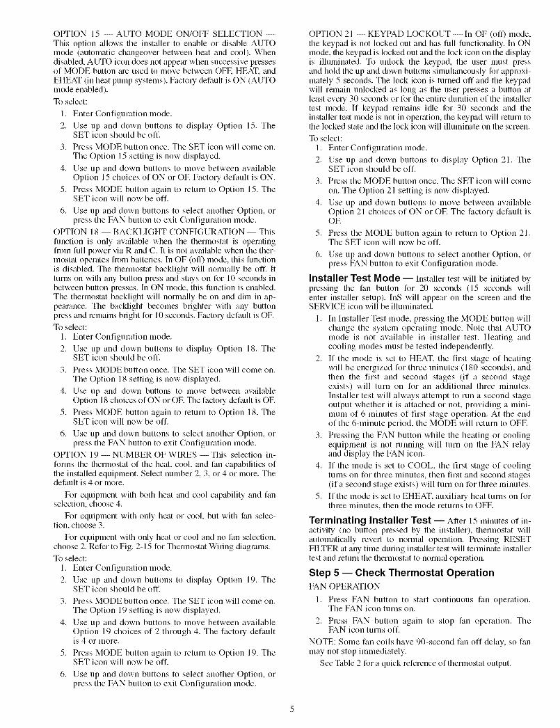
Fig. 10 -- Two-Speed Air Conditionerwith Typical Fan Coil
MODEL 0100-CTHERMOSTAT
24 VAC HOT
HEAT STAGE 1
COOL STAGE 1
FAN [_--
24 VAC COMM
EASY SELECTTERMINAL BOARD
E}.... E_
--I-i_
.... ]
.... D
[][]
SINGLE-SPEEDAIR CONDITIONER
I J1 JUMPER
I J2 JUMPER
q_•
-q-l-q
See Notes 10 and 11.
Fig. 12 -- Single-Speed Air Conditionerwith Variable-Speed (FK4D, FV, 40FK) Fan Coil
MODEL 0300-CTHERMOSTAT
I--I
24 VAC HOT RL_ _ _.
D-24 VAC COMM
COOL/HEATSTAGE 2
V-_ cHEAT STAGE 3 ° ---I
I--I
RVS COOLING IO/B_21
COOL/HEAT B - -- ]STAGE 1
N/A []
OUTDOOR {____]SENSOR
CONNECTION
TYPICAL TWO-SPEEDFAN COIL HEAT PUMP
_____#__
-#-F_
_#__-q-Fq
See Notes 5 6, 78, 10, and 11.
Fig. 11 -- Two-Speed Heat Pumpwith Typical Fan Coil
MODEL 0200-C EASY SELECT SINGLE-SPEEDTHERMOSTAT TERMINAL BOARD AIR CONDITIONER
24 VAC HOT I_--
HEAT STAGE 1
24 VAC COMM E],-
COOL STAGE 1
FAN [_--
E}
.....
FI
HEAT STAGE 2 _ ...... D
NJA [] []NJA [] []
OUTDOORI--FISENSOR --I
CONNeCT'ONLF_
I J1 JUMPER
REMOVEJ2 JUMPERFOR HEATSTAGING
See Notes 2, 4, 10 and 11,
Fig. 13 -- Single-Speed Air Conditionerwith Variable-Speed (FK4D, FV, 40FK) Fan Coil

MODEL 0300-CTHERMOSTAT
24 VOLT HOT E_-- - --
24 VOLT COMM _ --
FAN [_-----
COOL STAGE 2 _ ---
HEAT STAGE 1 _ -- -
EASY SELECT TWO-SPEEDTERMINAL BOARD AIR CONDITIONER
I_ ] J,JOMPER-D -q-%-E]- -q-rc-q-D
........ q-FI
HEAT STAGE 2_ -- -
COOL STAGE 1 E_
N/A []
OUTDOOR F[]
oSE ESO, o D
[]
'J2 JUMPERFOR HEATSTAGING
_q-F4
See Notes 2, 4, 8, 10, and 11.
Fig. 14 -- Two-Speed Air Conditioner withVariable-Speed (FK4D, FV4, 40FK) Fan Coil
MODEL 0300-CTHERMOSTAT
24 VAC HOT
24 VAC COMM
FAN
COOL/HEATSTAGE 2
HEAT STAGE 3
RVS COOLING_
COOL!HEAT E_STAGE 1
N/A []
OUTDOOR EE!]
SENSOR qlCONNECTION LD
EASY SELECTTERMINAL BOARD
TWO-SPEEDHEAT PUMP
m
E_-[]-.-[]--[]
-E_
EP
_[]-
J1 JUMPER
J2 JUMPER
_-r-I
_-lWl
See Notes 7, 10 and 11.
Fig. 16 -- Two-Speed Heat Pump withVariable-Speed (FK4D, FV4) Fan Coil
MODEL 0200-C EASY SELECT SINGLE-SPEEDTHERMOSTAT TERMINAL BOARD HEAT PUMP
24 VAC HOT _ - -- -
24 VAC COMM [_ - -- -
FAN [_-- ----
COOL/HEAT _ ---STAGE 1
HEAT STAGE 2 _ ----
N/A []
RVS COOLING _ ----
N/A []
OUTDOOR Fr _
oSE ES° o r
m
J1 JUMPER _--E_
-[]- ....... _q-E]-[]
-q-E]-E_
J2 JUMPER
El- ....... _q-D-E]- ......... -[][]
See Notes 7, 8, and 11.
Fig. 15 -- Single-Speed Heat Pump withVariable-Speed (FK40, FV4, 40FK) Fan Coil
NOTES FOR FIG. 2-16
1. Furnace must control its own second-stage heat operation viafurnace control algorithm. Refer to indoor equipment Installa-tion Instructions for proper setup.
2. See Option 5 information to convert HP and 2S thermostats toAC thermostat operation.
3. As an option, lock the furnace into low-heat operation and letO/W2/B control high-heat operation. Refer to indoor equipmentInstallation Instructions for proper setup.
4. O/W2/B can control second-stage heat. Refer to indoor equip-ment Installation Instructions for proper setup.
5. Refer to outdoor equipment Installation Instructions for latent kitrequirements (if any).
6. Terminals marked with * may not be present on equipment.7. O/W2/B energizes reversing valve in cooling or heating. See
Option 10.8. Refer to outdoor equipment Installation Instructions for proper
setup.9. If system is wired per diagram, the ACRDJ (jumper) on furnace
control board should be removed to allow thermostat to controloutdoor unit staging.
10. Refer to fan coil Installation Instructions for proper wiring.11. If batteries are installed, C (common wire) is not required
between indoor unit and thermostat.
OPERATIONAL INFORMATION
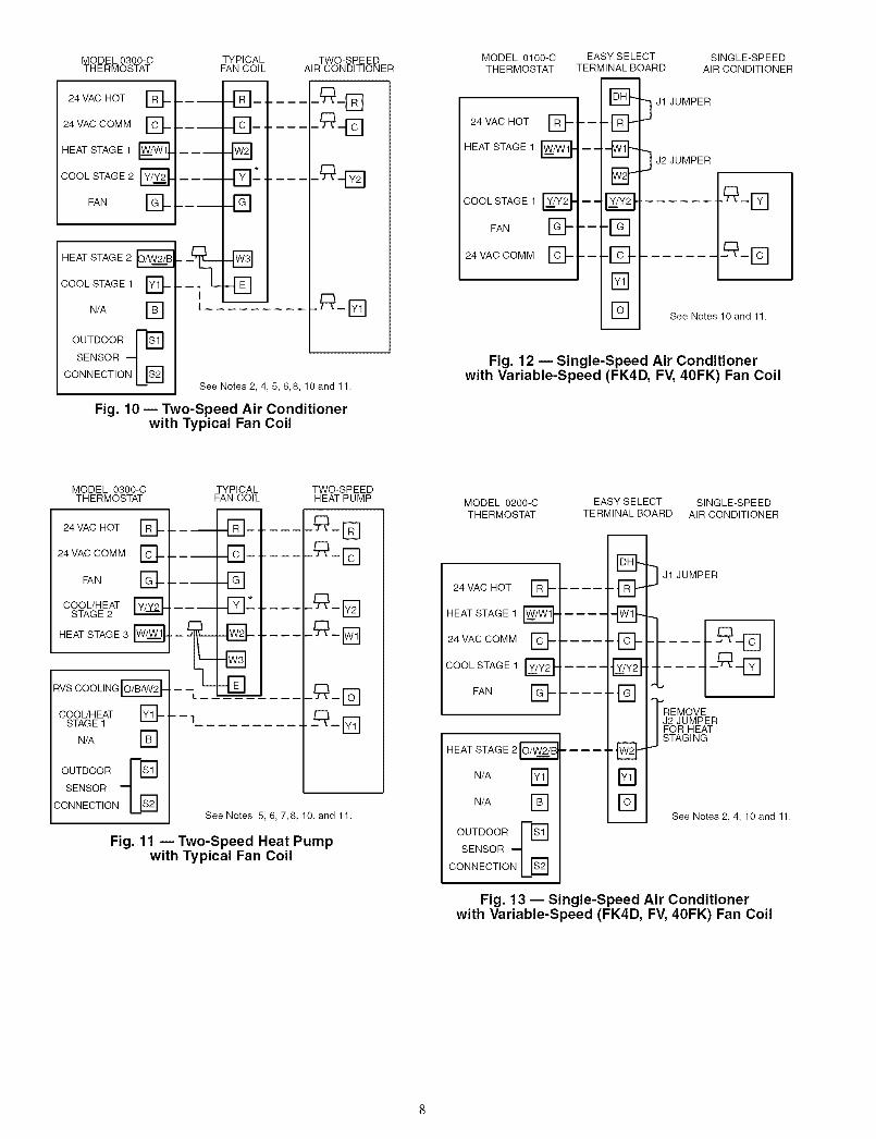
Five-Minute Compressor Time Guard -- This tim-er prevents the compressor from starting unless it has been offfor at least 5 minutes. It can be defeated for 1 cycle by simulta-neously pressing the FAN mode button and the INCREASETEMPERATURE button.
Fifteen-Minute Cycle Timer -- This timer preventsthe stall of a heating or cooling cycle until at least 15 minutesaller the last st;ut of the salne cycle. Its fimction is to assure thatequipment is not cycled more than 4 times per hc This timer isdefeated for 1 cycle when the desired temperatme is manuallychanged. It can also be defeated for 1 cycle by simultaneouslypressing the FAN mode button and file INCREASE TEMPER-ATURE button.
Fifteen-Minute Staging Timer -- In multistage heat-ing or cooling, this timer prevents any higher stage fromturning on until the preceding stage has been on for 15 minutes.This timer is defeated if the temperature error is greater than5° F (usually due to a lmge change in desiled temperature).
Three-Minute Minimum On Time -- In normal op-eration, when a stage turns on, it will not turn off for a minimumof 3 minutes.
Heat/Cool Set Points (Desired Tempera-tures) -- A minimum diffelence of 2° F is required betweenheating and cooling set points. This is done by allowing onesetting to "push" the other, to maintain this difference.
Auto Changeover -- When the autochangeover mode isselected, a change from heat to cool (or vice versa) will notoccur until an opposite mode demand has existed for 20 min-utes. If the set point is changed, the 20-minute requirement isdeleted. Auto mode may be disabled.
Emergency Heat Mode -- When thermostat is config-ured as a heat pump and Emergency Heat mode is selected, allY signals are locked out and W becomes energized upon a callfor heat.
Heat On and Cool On Icons -- When a heating orcooling demand exists, the HEAT ON or COOL ON icon willeither remain on or flash. If flashing, the equipment is tempo-rarily prevented from turning on by one of the timel_ (seeabove). While the icon remains on without flashing, the equip-ment is on.
Power On Check -- When AC power is first applied, allsegments of file display are turned on for a few sec. Followingthis, the temperature display indicates the model/configurationvia the following 2-digit code: AC -- 1-speed air conditioneLHP -- l-speed heat pump, A2 -- 2-speed air conditioner,H2-- 2-speed heat pump.
Error Codes
-- -- If the thermostat cannot properly read room temperature,the display will indicate -- (2 dashes) and all outputs (exceptthe fan if on) will turn off. This is to plevent operation of theequipment if the thermostat has failed.
E2 -- If the AC line voltage drops below a minimum (brown-out) level, all outputs are turned off and file display indicatesE2. This condition will remain for 15 sec ;trier proper line volt-age is restored. If the AC line voltage disappems completely,the display will immediately go blank.
E3 -- If the thermostat cannot propedy read outdoor tempera-ture, and it is needed for proper operation (heat pump systemand Option 8 is not set to OF), E3 will flash ;alternately withroom temperature. See Table 3 for error code descriptions.
Table 3 -- Thermostat Troubleshooting
SYMPTOM WHAT TO CHECK
Blank LCD Check for 24 vac between R and C at terminal connections or battery.
Temperature sensor reading out of range. Check sensor for damage. If recycling power"--" (2 dashes) on temperature display does not clear display, thermostat should be replaced.
"E2" on temperature display Brownout condition or too low of voltage to thermostat. Double check wiring and check for24 vac between R and C. E2 will clear 15 sec after proper voltage is restored.
"E3" on temperature display The outdoor temperature sensor is open, not connected, or shorted.
After the selected number of hour of blower operation "FILTER" will display on LCD. This"SERVICE FILTER" on temperature display is to remind the home owner to "check" the filter. Press RESET FILTER button to clear
display and reset timer to 0.
Select COOL mode. Set desired temperature to 10° F below room temperature. Simulta-neously press FAN and INCREASE TEMPERATURE buttons to defeat timers. Check for
Cooling will not come on COOL ON icon and 24 vac at Y (first-stage) terminal. If present, thermostat is okay and_roblem is with equipment or wiring. If not present, replace thermostat.
Select HEAT mode. Set desired temperature to 10° F above room temperature. Simultaneously3tess FAN and INCREASE TEMPERATURE buttons to defeat timers. Check for HEAT ON and
Heating will not come on 24 vac at Y (first-stage) terminal (with heat pump) or W/W1 (with air conditioner) terminal. If_resent, thermostat is okay and problem is with equipment or wiring. If not present, replace
thermostat.
10

NON-PROGRAMMABLE THERMOSTAT CONFIGURATION RECORD
OWNER/OPERATOR:
HARDWARE CONFIGURATION
Seal hole in wall.
DATE:
THERMOSTAT MODEL NO:
I1. MODE SETTINGS
Mode (Off, Heat, Cool, Auto, Eheat)
Heating Set Point Value
Cooling Set Point Value
Fan (Auto or On)
III. CONFIGURATION OPTIONS
l
2
3
4
5
6
7
8
9
l0
ll-12
13
14
15
16-17
18
19
20
21
Anticipator (1-9: factory default = 3)
Clean Filter Timer (OF or 1-9: facto U default = 2)
Fahrenheit or Celsius (F or C: factory default = F)
Fan On with W/Wl output (OF or ON: factory default = OF)
HP (2-speed)/AC Configuration
Cooling Ix)ckout (OF or ON: factory default = OF)
Zoning Selection (OF or ON: factory default = OF)
Auxiliary Heat Lockout (OF or 5 to 55 F: factory default = OF)
N/A
O (Reversing Valve) (ON with Heat or Cool Selection; default = C) (present on Heat Pump models only).N/A
Room Temperature Offset (-5 to +5: factory default = 0)N/A
Enable Auto Mode (OF or ON: factory default = On)
N/A
Backlight Configuration: (ON = Continuous; OF = Backlight with Keypress; Default = OF)
Number of wires (2, 3, 4 or more); Default = 4 or more
N/A
Keypad lockout (OF or ON: Default = OF)
11

Manufacturer reserves the right todiscontinue, or change at any time,
specincatlons or designs without noticeand without Incurring obligations.
REPLACEMENT COMPONENTS DIVISION©CARRIER CORPORATION 2004 9-04PRINTED IN U.S.A.
LITERATURE NUMBER P274-7SIREPLACES: 997-510011-19
CATALOG NUMBER 570-351