Embed Size (px)
Citation preview

Installation &
Maintenance Instructions For
‘S’ Series Hot Water Boilers
Imported by
PNA, Inc. 242 Miller Street
PO Box 8085 Bangor, Maine 04402
207-942-3636
207-942-3737 FAX [email protected]
Designed and Tested to the A.S.M.E. Boiler and Pressure Vessel Code

P E N S O T T I B o i l e r sP E N S O T T I B o i l e r s
1
TABLE OF CONTENTS
ANNUAL FUEL UTILIZATION EFFICIENCY Page 3
A GENERAL COMMENT Page 3
SELECTION OF BOILER SIZE Page 4
RECEIVING SHIPMENT Page 5
BOILER LOCATION Page 5
CLEARANCES Page 5
LEVELING UNIT Page 6
COMBUSTION AIR AND VENTILATION Page 6
PIPING Page 7
WIRING Page 9
VENTING REQUIREMENTS Page 9
FUEL SYSTEM Page 11
STARTUP PROCEDURE Page 12
SERVICE INFORMATION-HOMEOWNER Page 13
MAINTENANCE Page 13
BURNER AND NOZZLE SPECIFICATIONS Page 23

P E N S O T T I B o i l e r sP E N S O T T I B o i l e r s
2
NOTES

P E N S O T T I B o i l e r sP E N S O T T I B o i l e r s
3
A COMMITMENT TO QUALITY
PNA, Inc. is proud to supply you and our network of dealers with the high quality PENSOTTIModel ‘S’ Cast Iron Boiler throughout the North American marketplace.We are confident that your purchase of the PENSOTTI home comfort package will provide yearsof efficient, economical, trouble-free operation.
"Quality remains long after the price is forgotten".
The PENSOTTI ‘S’ boiler is a high efficiency residential heating appliance that provides maximumenergy utilization and the highest efficiency, without the maintenance and operations problems andhigh purchase and installation costs of condensing boilers.
Fuel cost savings can only be achieved by matching the PENSOTTI ‘S’ boiler to the true heat lossof your residence. During the past couple of decades, the trend towards improving wall and ceilinginsulation levels and eliminating air infiltration by caulking and weather-stripping, has made mostexisting heating appliances oversized.When you purchase a PENSOTTI home comfort system your new appliance will be sized on thebasis of the new heat loss calculation. This will ensure that your new PENSOTTI home comfortsystem will deliver only the amount of heat required to match your actual home’s heating demand.We want to provide you with the maximum comfort level achievable combined with the highest fuelcost savings.The following are useful bits of information presented under a series of sub-headings.
Annual Fuel Utilization Efficiency (A.F.U.E.)The A.F.U.E. is a measure of the estimated ability of a heating appliance to extract heat from thefuel, based on a full heating season.The A.F.U.E. increases as the burner on time increases until it reaches ‘steady-state efficiency’.Steady state is the efficiency of the appliance measured when the burner is running.Any time the burner cycles on and off, the A.F.U.E. drops because of "off-cycle" losses. TheA.F.U.E. drops most sharply when the heating plant operates between 10 and 30% burner on time.An increase in the percentage of burner on time improves the A.F.U.E.
A General CommentThe PENSOTTI Model ‘S’ boiler is a high quality, efficient oilfired heating appliance, which mustbe installed and serviced by a trained and if required licensed service technician.Oilfired installations should be installed in accordance with NFPA31 and NFPA211 when no localcode is in effect. Be sure that the installation is according to all National, State and local codes andauthorities having jurisdiction over heating, electrical, plumbing and oil burner systems.

P E N S O T T I B o i l e r sP E N S O T T I B o i l e r s
4
The electrical system to this unit should be supplied by a separate circuit provided with a fuseddisconnect switch at the service panel.
All boiler installations must conform to the A.S.M.E. Boiler Code. If the boiler requires NationalBoard approval consult PNA, Inc. for special order. Many states and local authorities requireNational Board inspection and registration for installation in buildings used for public assembly,more than four (4) apartments, etc.
It is important therefore that these instructions be followed carefully and that a competentPENSOTTI dealer installs the ‘S’ Series boiler only.The boiler should only be used as the primary heating source of a well-designed and installedhydronic heating.It is the responsibility of the installer to ensure that this boiler is installed properly and that allsettings and adjustments are made before putting the unit into service.
The boiler is provided with a Lifetime Limited Warranty. A copy of the warranty is availablethrough your PENSOTTI dealer.
Selection of Boiler SizeIt is important that the boiler be properly sized for the job. The boiler should be of a sufficientcapacity to satisfy the heat load and the domestic hot water load if the unit is to be used for thispurpose.
Most heating systems are oversized. In fact, recent US Government DOE and HUD surveys foundexisting equipment in the field to be as much as 400% oversized.Reducing the firing rate of the boiler results in longer burner on-times increased A.F.U.E. andprovides significant savings for the consumer.The improved A.F.U.E. of the PENSOTTI ‘S’ is highly effective heat generator when it is matchedto the heatloss of your home.
The first and only correct way to size the boiler is to determine the actual heat loss of the structureto be heated. DO NOT base the heat load on the existing radiation since this may not be adequate.If the boiler size is selected on this basis it may not heat the building properly. Also, take care nottoo oversize, since this may lead to short cycling and inefficient operation.
After computing a complete and actual heat loss of the structure, you may now select the correctboiler required. The correct boiler is selected by matching the boiler's Net I-B-R Rating to theactual heat loss of the building.

P E N S O T T I B o i l e r sP E N S O T T I B o i l e r s
5
If the calculated load exceeds the capacity of the largest size PENSOTTI ‘S’ boiler, two or moreunits may be installed. Modular installations can be a sound investment leading to an increase in fuelefficiency. Consult PNA, Inc. for further information on Modular (multiple) boiler installations andlarger boiler options.
All PENSOTTI ‘S’ boilers must be properly sized to provide domestic hot water. Use the waterheater manufacturer's charts to determine the correct BTU requirements for domestic hot waterservice.
Alternatively, the ‘K’ factor sizing method, which uses past energy consumption, based on theefficiency of the old appliance and local weather data may also be used.Replacement heating appliance installations should not use the existing applianceexclusively for determining the size of the new appliance.As previously noted, recent research indicates that existing installed appliances are often over-sized, resulting in excessive energy consumption.
Receiving ShipmentUpon receipt of shipment, inspect all items and cartons for external damage. If external damage isnoted, open the item or carton and inspect for damage to equipment. Mark the number of itemsreceived in this condition on the delivering carriers' waybill, and request the services of theirinspector.
If, upon opening the carton, concealed damage is found, open the entire shipment and note allequipment so damaged. Contact the delivering carrier, not PNA, Inc., and request inspection of thedamaged equipment. Do not destroy the carton. The inspector from the freight company will needthis to determine the reason for the damage.
Normally claims for any damages should be filed with the freight company within 5 working daysafter receipt of shipment. It is the responsibility of the consignee to file claim with the deliveringcarrier for material received in a damaged condition.Permission to return goods to PNA, Inc. must be authorized by us and are subject to a 15%restocking charge.
Boiler LocationThe boiler should be located on a dry, solid, non-combustible, level surface, preferably as close tothe chimney or venting inlet as possible, with a minimum of 90° vent elbows. Vent lengths over 10ft. does not reflect good installation practice.It is good practice however, to raise the boiler above the floor for service and piping.

P E N S O T T I B o i l e r sP E N S O T T I B o i l e r s
6
Clearances for Service and Combustible MaterialsService access to the boiler must be adequate to provide access around the boiler for cleaning andservicing. Consult local fire codes for required clearances.The easier the service accesses the higher the quality of service the unit will receive.
Minimum clearances for proper service are as follows:8" from the front of the oilburner,18" from the back of the unit, and one side2" from the other side.
The minimum installation clearances to combustible materials are:8” from the front of the oilburner and one side,18” from the back of the unit,2” from other side,18” from the chimney connector.
Leveling UnitIf the floor is uneven, the PENSOTTI ‘S’ boiler may easily be made level by inserting shims underthe four cast-iron legs.
Combustion Air and VentilationIf a PENSOTTI ‘S’ boiler is being used for a retrofit and is installed in a full basement withadequate infiltration for combustion air it may be installed in the usual way following acceptedindustry guidelines and good industry practices.
Fresh Air IntakeRecent energy conservation practices have resulted in many people insulating and caulking theirhomes to a level where the fresh air required for efficient combustion is not always readily available.Particularly if you choose to isolate your PENSOTTI boiler in an enclosed area of your home, afresh air intake must be installed in this area.
Air for CombustionThe PENSOTTI boiler must have an assured supply of combustion air. A dedicated outsidesupply of air through an installed duct or pipe should be installed at or within 5 ft. of the boiler. Ashut-off damper may automatically control the supply duct when the unit is not operating, but theoperating automatic damper must 'fail' in the open position. The combustion air duct must havedirect access to the outdoors and have a rain hood and insect screen installed at the outside wall.
Care should be taken when the boiler is to be installed within a home where the operation ofexhaust fans, attic fans, kitchen ventilation systems, new high efficiency clothes dryers or fireplaces
P E N S O T T I B o i l e r sP E N S O T T I B o i l e r s
7
may create severe negative vent pressures and unsatisfactory combustion and venting. Specialprovisions should be made for additional make-up air to supply the other air requirements.
In cases of electric heat conversions or any structure of tight construction an opening of one (1)square inch of minimum free area per 1000 BTU per hour of burner input must be provided. Theair supply to the burner must be provided directly to the burner and originate outside the structurewithin five feet (5') of the burner. The inlet vent must originate on the same wall surface as theboiler outlet vent, if a direct venting system is used. The inlet hood should be waterproof andinclude a bug and bird screen.In cases where the boiler is installed in an area where exhaust, kitchen or bath ventilation systemsand fans exist, they may create unsatisfactory combustion or venting conditions. Specialconsideration should be made for additional air.All combustion air and ventilation requirements should meet local code and or NFPA Standard 31.
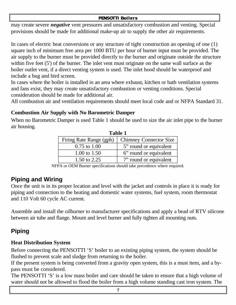
Combustion Air Supply with No Barometric DamperWhen no Barometric Damper is used Table 1 should be used to size the air inlet pipe to the burnerair housing.
Table 1Firing Rate Range (gph) Chimney Connector Size
0.75 to 1.00 5” round or equivalent1.00 to 1.50 6” round or equivalent1.50 to 2.25 7” round or equivalent
NFPA or OEM Burner specifications should take precedence where required.
Piping and WiringOnce the unit is in its proper location and level with the jacket and controls in place it is ready forpiping and connection to the heating and domestic water systems, fuel system, room thermostatand 110 Volt 60 cycle AC current.
Assemble and install the oilburner to manufacturer specifications and apply a bead of RTV siliconebetween air tube and flange. Mount and level burner and fully tighten all mounting nuts.
Piping
Heat Distribution SystemBefore connecting the PENSOTTI ‘S’ boiler to an existing piping system, the system should beflushed to prevent scale and sludge from returning to the boiler.If the present system is being converted from a gravity open system, this is a must item, and a by-pass must be considered.The PENSOTTI ‘S’ is a low mass boiler and care should be taken to ensure that a high volume ofwater should not be allowed to flood the boiler from a high volume standing cast iron system. The

P E N S O T T I B o i l e r sP E N S O T T I B o i l e r s
8
high flow will cause combustion problems from cool surface impingement within the boiler.If a high-pressure test of the existing hydronic system is necessary, the boiler itself must not beexposed to the pressure test. Isolate the boiler during the test.
Boiler Replacement and Service CautionThe replacement of old large cast iron and steel boilers with new modern compact efficient boilers(sometimes called low mass) can cause problems from corrosion being produced with lowoperating water temperatures.Combustion by-products in fuels produce acidic sulfur oxides which corrode cast iron and steelsurfaces, when the oxides condense in a water solution on the boiler surfaces.The water dewpoint on the inside surfaces of a boiler is 120°F (49°C) for fuel oil burning and140°F (60°C) for natural gas.
The fuel dictates the amount of acid compound in the combustion process. However, the presenceof chlorides in the combustion air greatly increases the rate for the production of mild acidcompounds that are very active on cast iron and steel surfaces.The safest operating temperature range for modern boilers, proven conclusively by tests, is 160°F(71°C) to 210°F (99°C). Allowing the boiler water temperature to drop below 160°F (71°C) isasking for increased rates of corrosion due to the acid becoming more corrosive due to dilutionwith water condensate. The rapid production of corrosion and cold flame temperatures can lead torapid boiler plugging.
The following step-by-step procedure should be followed for connecting the PENSOTTI ‘S’boiler to the existing heat distribution system:
1. Connect the boiler return and supply pipes to the main circulating system as selected.A pump-away type system is preferred, but conventional piping systems may also be used.
2. Install a manual shut-off valve on both the return line and supply line and on the boiler by-passloop. The by-pass loop is a must on all standing cast iron radiation systems. This eliminatesflooding (cold return) on a low mass boiler and gravity flow during off cycles. If thePENSOTTI ‘S’ Series Boiler is to be used with large water content systems, or the boiler willbe placed into use in a low water temperature system such as a converted gravity circulationsystem, a 1/2" bypass loop is recommended. The loop should run from the supply line to thereturn line with a gate valve, as shown in the drawings. With the valve full open the boiler shouldbe allowed to operate and the valve throttled to provide a 180°F to 200°F supply watertemperature. Failure to install this valve may lead to condensing of the flue gasses, corrosion ofthe heat exchanger and premature boiler failure resulting in a loss of warranty coverage.
3. A.S.M.E. Boiler Code requires feed or make-up water to be introduced to the piping systemand not directly to the boiler. Pressure reducing valves should be installed and adjusted to 12-psi cold water.
4. The maximum operating water temperature is 205°F (96°C).

P E N S O T T I B o i l e r sP E N S O T T I B o i l e r s
9
5. The maximum operating water pressure is 30 psi.6. The pressure relief valve must be piped from the boiler and downward to within 6 in. of the
floor (or by code) to avoid the potential for accidental face and body injuries.7. An expansion tank, circulating pump and automatic air eliminators must be part of the system.
See typical piping diagrams on pages 14 through 17.8. Recommended location of circulator, expansion tank, relief valve and other trim is shown in
Figure 1, Figure 2, Figure 3, and Figure 4.9. The relief valve, backflow-preventer and drain valve should be piped according to code and
should be piped to discharge safely.10. If the PENSOTTI ‘S’ is to be used with a storage type domestic hot water system other than
provided by PNA, Inc. connect and wire according to manufacturer's instructions.
WiringAll external wiring must conform to existing electrical codes laid down by the authorities havingjurisdiction.In the United States this is generally the National Electrical Code, NFPA70.In Canada, they are the C.S.A. Standard C22-1 and the Canadian Electrical Code.
1. Field connections should be properly sized, and protected with a minimum 15-amp fusetron orcircuit breaker.
2. Install a separate fused disconnect switch as required (or by code) so power can be shut off forservicing.
3. Ground the boiler to the water piping.4. Install the room thermostat or relocate the room thermostat away from cold drafts, air currents,
lamps, televisions or sunlight. Set the heat anticipator on the thermostat to match the operatingcontrol. Connect the thermostat leads to the circulation pump operating control or aquastat asapplicable.
5. The PENSOTTI ‘S’ is supplied with the control package ordered by your dealer, and all wiringshould be as specified in the accompanying manual.Wiring diagrams using various available controls are shown as Figure 5, Figure 6, Figure 7,and Figure 8.The optional ERIE ‘Boiler Boss’ is shown in Figure 9, on page 22.
Special Control SystemsFor special control systems such as multiple zones, multiple boiler installations, unit heaters, radiantheating, etc. consult the respective control manual or contact PNA, Inc. for further information.
Venting RequirementsOil fired appliances shall be connected to flues or vents having sufficient draft at all times to ensuresafe and proper operation of the appliance.

P E N S O T T I B o i l e r sP E N S O T T I B o i l e r s
10
When venting the PENSOTTI Model ‘S’ boilers, all installations should conform to all national,local and State codes and authorities having jurisdiction.When no local code is in effect NFPA-31 should be used as a reference, and baseline document.In addition, the design of chimney connectors, chimneys, power-venting systems and direct ventsystems should also conform to local and State codes, and good industry practice. In lieu of localcodes, NFPA-211 should be used as a reference.Natural Draft ApplicationsAfter placing the boiler within close proximity to the venting system, the following basic guidelinesshould be observed that would prevent the following conditions from occurring:
• Condensation of flue gasses.• Positive outlet draft conditions.• Reverse flow of fluegas during or after burner shutdown.
In addition, the following rules of good industry practice should be followed;1. Always try to keep chimney connector length to ten feet (10’), or less.2. The chimney connector must never be smaller than the boiler flue outlet, and should be
constructed of at least 24-gauge metal.3. NEVER connect the appliance into a chimney or liner serving an open fireplace.4. Inspect and clean chimney, and verify it is free of restrictions and obstructions.5. The chimney connector must always be properly supported.6. NEVER install a manual damper in the venting system.7. Chimney connectors should be free of as many 90° degree turns as possible, and be pitched
upwards towards the vent.8. It is important to note that due to the high efficiency of the PENSOTTI Model S boilers
condensing temperatures in the chimney connector and venting system may be reached.If condensing temperatures of below 250° F NET are reached in the chimney connector, thefollowing precautions may have to be taken;
9. Seal all joints in venting system with high temperature silicone or mastic.10. Verify quality of chimney and liner. If a masonry, brick, or block chimney is used, or the
existing tile liner is in poor condition, a chimney liner suitably rated, and listed for oil may haveto be installed.
Mechanical Draft ApplicationsWhen using the PENSOTTI Model ‘S’ boilers in a mechanical draft application the following basicguidelines should be observed according to the venting system in use. In addition, it is stronglyrecommended that the applicable precautions for Natural Draft Applications be used.
Power Venter ApplicationsWhen using a power venter, all of the recommendations and instructions of the OEM of the powerventer MUST be followed and the entire installation must conform to any and all local, State, andNational codes.
P E N S O T T I B o i l e r sP E N S O T T I B o i l e r s
11
Direct Vent ApplicationsWhen using a PENSOTTI Model ‘S’ on a ‘sealed’ or ‘direct’ vented system, the installation mustconform to any and all local, State, and National codes.In addition, all of the pertinent information regarding Natural Draft Applications should be usedalong with the following instructions;
• The terminating vent hood, and the inlet air hood are on the same wall surface, and are on thewall opposite from the prevailing wind wall, if possible.
• All of the air for combustion to the burner is supplied directly from outside of the building orstructure.
• All of the vent construction consists of suitable materials, and terminates in an approvedstainless steel hood.
• All of the vent piping is sealed from air leaks.
The PENSOTTI ‘S’ oilfired boiler is not approved for use with a heat extractor mounted in thebreeching or fluepipe.
Draft RegulatorThe PENSOTTI ‘S’ boiler does not normally require a barometric damper, but, it may be requiredwhen the draft in the venting system is stronger than required, and the burner is incapable ofoperating against a high negative over-fire pressure.
Roof ClearancesStandard roof clearances apply. It is the responsibility of the installer to ensure they are adequate.
FUEL SYSTEMEnclosed with each burner are the pump manufacturers' specifications, which the fuel systempiping should conform to.In addition the following suggestions are highly recommended.1. All fuel system piping must meet local codes and ordinances.2. The burner is designed to burn clean, water-free #1 or #2 heating oil only. Use of #1 is
recommended where outside tanks are exposed to temperatures below zero (0) degrees F.3. The oil supply line should be clean and free of kinks and restrictions.
An old (i.e. in excess of 15 years) fuel supply line should be replaced with new copper tubing.This will ensure a clean fuel supply.
4. Fuel lines must be airtight and be constructed of seamless heavy wall copper tubing and onlyflared fittings should be used. The use of Teflon tape is prohibited and will void manufacturers'warranties. Use only oil resistant pipe dope on all threaded connections. Check all joints andthreaded fittings for leaks. Use a vacuum gauge to proof the installation.
5. The use of a two-pipe system should only be used when necessary and when the oil supply iswell below the pump. A return fuel line may be used on an installation where the fuel level of the
P E N S O T T I B o i l e r sP E N S O T T I B o i l e r s
12
tank is below the level of the burner. The return line must be equal to the suction line. Theminimum size oil line should be 3/8 in. copper tubing.
6. The use of a two-stage fuel unit or a device like the Tigerloop is recommended when the oilsupply is located ten feet (10') below the burner.
7. The use of double filtration is recommended to ensure maximum longevity of the pump andnozzle. The use of a low micron paper filter is also recommended. The filter(s) should beproperly sized to the Total Gear Suction Capacity (TGSC) of the pump in use. Leave theexisting felt filter, normally found at the tank, in place. Fit the fuel suction line with a high qualitypaper throwaway cartridge type filter or line strainer. A rating of 5 micron to 10-micronmaximum rating is recommended. The paper filter or strainer should be mounted on the casingof the boiler. This will allow the use of flexible fuel lines to be connected with adequate slackfor easy removal of the oil burner or use of the swing door without disconnecting the fuel lines.
8. A shut-off valve must be installed in the fuel supply line located at or near the oil storage tankand at the burner in compliance with local codes. The shut-off valve spindle packing should bechecked for tightness to eliminate potential air leaks into the fuel delivery system. Always keepthe valve shut off if the burner is shut down for an extended period of time. Tag the burner toindicate that the fuel supply is closed and shut off the circuit breaker or remove the fuse fromthe electrical circuit to eliminate improper operation due to lack of fuel.
9. Use of fuel storage tanks bearing the label of Underwriters Laboratories and approvedaccessories prescribed by local codes is required.
CRANKCASE OIL, WASTE OIL, OR GASOLINESHOULD NEVER BE USED!
The danger of explosion and personal injury is VERY HIGH when GASOLINE ispresent in fuel source!Never attempt to burn garbage or paper in the heating unit and remove all paper and ragsfrom around the unit.For your safety, do not store or use gasoline or other flammable vapors or liquids in thevicinity of this or any other heating appliance.

P E N S O T T I B o i l e r sP E N S O T T I B o i l e r s
13
START UP PROCEDURE1. Make certain service switch is off.2. Check all fittings and wiring.3. Be certain the boiler and heating system are completely filled with water. Purge all air from
system and ensure that proper system pressure is obtained. Twelve (12) PSIG-Minimum.4. Make certain that correct voltages have been applied to all circuits.5. Check to make sure that oil storage tank is filled with clean #1 or #2 heating oil.6. Make sure that all manual shutoffs are open in the system.7. Set operating controls to desired or recommended settings.8. Following the burner manufacturer's instructions set the oil burner for proper light off and
starting. Using accurate combustion test equipment set the burner for proper "steady-state"operation. Use of instruments is necessary to ensure proper operation and to achieve maximumefficiency that will yield the lowest possible fuel and operating costs.
9. Leave all consumer information, the burner manual, the control manual and this manual on thejob. Make sure your customer is aware of them.
SERVICE INFORMATION - HOMEOWNERHave your PENSOTTI ‘S’ boiler, oil burner, flue and venting system serviced at regular intervalsby your PENSOTTI Dealer. Your dealer will recommend how often your PENSOTTI boilershould be serviced.If a problem occurs, please check the following before calling your PENSOTTI Dealer:
1. Be sure there is oil in the tank and that all oil valves are open.2. Be sure the thermostat is set above the room temperature.3. Be sure all switches are on and that fuses are not blown.4. DO NOT TAMPER ANY FURTHER WITH THE UNIT, UNIT PIPING, and
WIRING OR CONTROLS.
P E N S O T T I B o i l e r sP E N S O T T I B o i l e r s
14
MAINTENANCE - SERVICEMANClean Boiler:Boiler must be properly cleaned to maintain correct and efficient operation.
1. Turn off all electrical power to unit.2. Remove fluepipe, open front door.3. Remove rear boiler door and insulation.4. Inspect combustion area and if necessary wire brush firesides and firepot.5. Reclose all doors.6. Replace fluepipe and seal all joints.
Clean Fuel System and Burner:Fuel system and burner must be properly serviced to ensure safe and efficient operation. Checkburner manual for proper servicing of burner supplied and that the following items are covered:
1. Service fuel filter(s) and fuel unit.2. Service burner housing and fan.3. Replace nozzle with correct type and size.4. Service ignition system.5. Service and check for proper operation of primary control.
Perform Combustion Test:Adjust burner for proper operation ensuring the best CO2 or O2 with no more than a Trace ofsmoke. This may require several adjustments to the burner and additional readings after eachadjustment.

P E N S O T T I B o i l e r sP E N S O T T I B o i l e r s
15
Flow Check
Drain ValvePiped to Floor
(or Code)
Relief Valve
DiaphragmExpansion
Tank
PressureReducing
Valve
BoilerFeed
Piped to Code
Purge Valve
Air Separator
Air Vent
Flow Check
Circulator SU
PP
LY
RE
TU
RNT
OS
YS
TE
M
MODELS
BOILER
Burner
Figure 1
Figure 1 shows a typical installation with no domestic hot water and noby-pass loop installed.

P E N S O T T I B o i l e r sP E N S O T T I B o i l e r s
16
Flow Check
Drain ValvePiped to Floor
(or Code)
Relief ValveDiaphragmExpansion
Tank
PressureReducing
Valve
BoilerFeed
Piped to Code
Purge Valve
Air Separator
Air Vent
Flow Check
Circulator SU
PP
LY
RE
TU
RNT
OS
YS
TE
M
MODELS
BOILER
Burner
Control Valvein
By-Pass Line
Figure 2
Figure 2 shows a typical installation with no domestic hot water and with aby-pass loop installed.The control valve should be either a needle or throttling valve.

P E N S O T T I B o i l e r sP E N S O T T I B o i l e r s
17
Flow Check
Drain ValvePiped to Floor(or Code)
Relief Valve
BoilerFeed
Piped to Code
Purge Valve
Air Separator
Air Vent
HeatingCirculator S
UP
PL
Y
RE
TU
RN
TO
SY
ST
EM
Control Valvein
By-Pass Line
DomesticCirculator
Figure 3
Burner
MODELS
BOILER
INDIRECTHOT
WATERHEATER
Figure 3 shows a typical installation with domestic hot water supplied by anindirect heater and with a by-pass loop installed.The control valve should be either a needle or throttling valve.

P E N S O T T I B o i l e r sP E N S O T T I B o i l e r s
18
Flow Check
Drain ValvePiped to Floor(or Code)
Relief Valve
BoilerFeed
Piped to Code
Purge Valve
Air Separator
Air Vent
HeatingCirculator
SU
PP
LY
RE
TU
RN
TO
SY
ST
EM
MODELS
BOILER
Burner
DomesticCirculator
INDIRECTHOT
WATERHEATER
Figure 4
Figure 4 shows a typical installation with domestic hot water supplied by anindirect heater and with no by-pass loop installed.

P E N S O T T I B o i l e r sP E N S O T T I B o i l e r s
19
Figure 5Figure 5 shows a typical installation with no domestic hot water supplied,and the addition of an optional low-water cutoff.

P E N S O T T I B o i l e r sP E N S O T T I B o i l e r s
20
Figure 6Figure 6 shows a typical installation with no domestic hot water supplied,and the wiring for an optional RIELLO burner.
P E N S O T T I B o i l e r sP E N S O T T I B o i l e r s
21
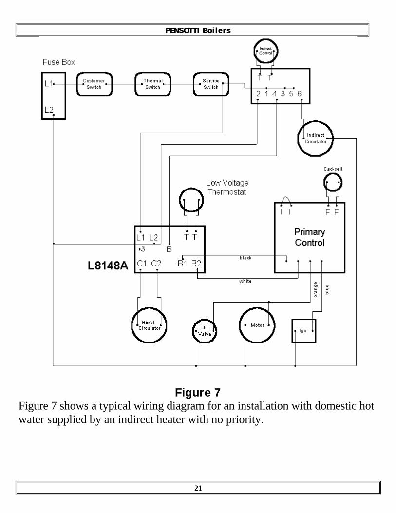
Figure 7Figure 7 shows a typical wiring diagram for an installation with domestic hotwater supplied by an indirect heater with no priority.

P E N S O T T I B o i l e r sP E N S O T T I B o i l e r s
22
Figure 8Figure 8 shows a typical wiring diagram for an installation with domestic hotwater supplied by an indirect heater with priority.

P E N S O T T I B o i l e r sP E N S O T T I B o i l e r s
23
CustomerSwitch
ServiceSwitch
ThermalSwitch
L1
L2
Fuse Box
BLK
WHTE
GRN
XFMR
XFMR
C2
C1
B2
B1
PiroCirc2
PiroCirc1
T2 T1 P2 P1 TV 24VAC 24VAC
AIR AIR GND H20 H20 GND SA
FE
TY
SA
FE
TY
Safety cut-off
OutdoorAir
Sensor
BoilerTemp
Sensor
N L
Hot WaterTemp
Controller
to
RoomThermostat
HeatCirculator
PriorityCirculator
RielloF40
ERIEBoiler Boss
2400
Figure 9
Figure 9 shows a typical wiring diagram for an installation with domestic hotwater supplied by a priority heater, outdoor reset and low water cut-off withone zone of heating.
P E N S O T T I B o i l e r sP E N S O T T I B o i l e r s
24
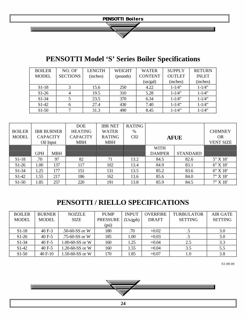
PENSOTTI Model ‘S’ Series Boiler Specifications
BOILERMODEL
NO. OFSECTIONS
LENGTH(inches)
WEIGHT(pounds)
WATERCONTENT
(us/gal)
SUPPLYOUTLET(inches)
RETURNINLET(inches)
S1-18 3 15.6 250 4.22 1-1/4” 1-1/4”S1-26 4 19.5 310 5.28 1-1/4” 1-1/4”S1-34 5 23.5 370 6.34 1-1/4” 1-1/4”S1-42 6 27.4 430 7.40 1-1/4” 1-1/4”S1-50 7 31.3 490 8.45 1-1/4” 1-1/4”
BOILERMODEL
IBR BURNERCAPACITY
Oil Input
DOEHEATING
CAPACITYMBH
IBR NETWATERRATING
MBH
RATING%
C02 AFUECHIMNEY
ORVENT SIZE
GPH MBHWITH
DAMPER STANDARDS1-18 .70 97 82 71 13.2 84.5 82.6 5” X 18’S1-26 1.00 137 117 102 13.4 84.9 83.1 6” X 18’S1-34 1.25 177 151 131 13.5 85.2 83.6 6” X 18’S1-42 1.55 217 186 162 13.6 85.6 84.0 7” X 18’S1-50 1.85 257 220 191 13.8 85.9 84.5 7” X 18’
PENSOTTI / RIELLO SPECIFICATIONS
BOILERMODEL
BURNERMODEL
NOZZLESIZE
PUMPPRESSURE
(psi)
INPUT(Us/gph)
OVERFIREDRAFT
TURBULATORSETTING
AIR GATESETTING
S1-18 40 F-3 .50-60-SS or W 180 .70 +0.02 .5 3.0S1-26 40 F-5 .75-60-SS or W 185 1.00 +0.03 .5 3.0S1-34 40 F-5 1.00-60-SS or W 160 1.25 +0.04 2.5 3.3S1-42 40 F-5 1.20-60-SS or W 160 1.55 +0.04 3.5 5.5S1-50 40 F-10 1.50-60-SS or W 170 1.85 +0.07 1.0 3.8
S1-08-00

P E N S O T T I B o i l e r sP E N S O T T I B o i l e r s
25
FOR FURTHER TECHNICAL INFORMATION CONTACT:PNA, Inc.
242 Miller StreetPO Box 8085
Bangor, ME 04402207-942-3636
This manual was prepared byFIREDRAGON ENTERPRISES
132 Lowell StreetArlington, MA 02474-2756
888-443-2825
Copyright 1997-2000TWC Publications

P E N S O T T I B o i l e r sP E N S O T T I B o i l e r s
26
NOTES