Embed Size (px)
Citation preview

Installation & Operation Manual
Commercial Back BarRemote & Self-Contained, Standard height and low height
Models BBR, BBS, BBRLP & BBSLP Series
Form No. 222201303.23.2016
Model BBSLP108 Shown
Models BBR/BBS & BBRLP/BBSLP Installation & Operation Manual
Printed in USA 2 Form No. 222201303.23.2016
TABLE OF CONTENTS
IMPORTANT!Read and understand all information in this manual before attempting the installation.
All plumbing and electrical work must be performed by a qualified technician and conform to all applicable state and local codes.
GENERAL INFORMATION
WarrantyTo register your product, visit our web site at www.perlick.com. Click on “Commercial”, then “Service”. Click on the link “Warranty Registration Form”. You must complete and submit this form or the installation date will revert back to the ship date.
Please record the purchase date and the dealer’s name, address and telephone number below.
Model Number: ________________________Serial Number: _________________________Purchase Date: _______________________Dealer Name & Address__________________________________________________________________________________________________________________Phone Number__________________________
SAFETY
PLEASE READ all instructions completely before attempting to install or operate the unit. Take particular note of the DANGER, WARNING an CAUTION information in the manual. The information is important for the safe and efficient installation, operation and care of your Perlick unit.
DANGER Indicates a hazard that WILL result in serious injury or
death if precautions are not followed.
WARNING Indicates a hazard MAY cause serious injury or
death if precautions are not followed.
CAUTION Indicates a hazard where minor injury or product
damage may occur if precautions are not followed.
IntroductionCongratulations on your purchase of a Perlick commercial back bar product. This manual has been prepared to assist you in the installation of your cabinet and to acquaint you with its operation and maintenance.
We dedicate considerable time to ensure that our products provide the highest level of customer satisfaction. If service is required, your dealer can provide you with a list of qualified service agents. For your own protection, never return merchandise for credit without our approval.
We thank you for selecting a Perlick product and assure you of our continuing interest in your satisfaction.
General Information ................................................................................................................................. 2Safety ...................................................................................................................................................... 2Prior To Installation .................................................................................................................................. 3Installation ............................................................................................................................................... 4Operation ................................................................................................................................................. 5Adjustments ............................................................................................................................................. 6Maintenance ............................................................................................................................................ 9Troubleshooting ..................................................................................................................................... 12Dimensions ............................................................................................................................................ 14Wiring Diagrams .................................................................................................................................... 19Warranty ................................................................................................................................................ 24
Models BBR/BBS & BBRLP/BBSLP Installation & Operation Manual
Printed in USA 3 Form No. 222201303.23.2016
PRIOR TO INSTALLATION
Uncrating and InspectionRemove all crating material. Carefully inspect cabinet for hidden damage. If damage is discovered, file your claim immediately with the transport company. Perlick is not responsible for damage in transit.
CAUTION Do not cut cardboard sleeve covering the unit.
Cutting may result in damage to the exterior of the cabinet. Failure to follow this procedure may damage the compressor and void warranty.1. Uncrate the unit on flat, level surface. Remove
the cardboard sleeve by removing the banding securing the sleeve to the shipping base. Carefully lift the cardboard sleeve up over the top of the unit.
2. Carefully lift unit off the base and onto a hand truck or dolly. Make sure unit is balanced on transporting device using soft, flexible strapping. Protect unit surfaces with cloth material where strapping contacts unit.
CAUTION Do not lift unit by drawer, shelving or door handles
or damage to the unit could occur.
WARNING To prevent personal i n j u r y, t w o p e o p l e
minimum required to lift the unit. Larger units may require additional personnel.3. Before moving unit, secure door(s) to unit with
tape to prevent from opening.4. Carefully move unit to installation site and
place in front of opening.
CAUTION Finished flooring should b e p r o t e c t e d w i t h
appropriate material to avoid damage from moving the unit.Plumbing
CAUTION Do not over-tighten drain fitting or damage to the
threads could occur.Condensate from the cooling coil is automatically evaporated from the condensate pan located in the condensing unit housing on self-contained models.Each unit is equipped with a floor drain located in the right rear corner of the cabinet. The drain can be plumbed to an external floor drain by connecting to the 3/4” NPT thread connection on
the side, or the 1” NPS thread connection out the bottom, of the unit. Both drain ports come plugged from the factory and can be removed if needed.NOTE: Remote units require evaporator condensate to be plumbed to an external drain.ElectricalThe cabinet must be connected to a separately fused power source (see Electrical Specification Plate affixed to unit) in accordance with National and Local electrical codes.Self-contained Perlick units come equipped with a NEMA 5-15P 90° plug with an 8’ cord extending beyond the rear of the cabinet. The electrical outlet must be flush with, or recessed into, the wall surface.NOTE: Never use an extension cord to extend the power cord to the electrical receptacle.
CAUTION If unit has been laid on its back or sides, place unit
upright and allow minimum of 24 hours before connecting power. Failure to follow this procedure may damage the compressor and void the warranty.
CAUTION Do not attempt to operate the equipment on any
other power source than that listed on the Electrical Specification Plate attached to the unit.
DANGER ELECTROCUTION HAZARD! Electrical grounding is
required. Appliances furnished with a 3-prong (grounding) polarized plug are equipped for your protection against possible shock hazards.• Never remove the round grounding prong
from the plug.• Never use a 2-prong adapter.• Never use extension cord to connect
power to the unit.• If a 2-prong receptacle is encountered, or
a longer power cord is required, contact a qualified electrician to have it replaced in accordance with applicable electrical codes.
DANGER Failure to comply with these electrical guidelines may
result in possible death or serious injury, fire, or loss of property.
Models BBR/BBS & BBRLP/BBSLP Installation & Operation Manual
Printed in USA 4 Form No. 222201303.23.2016
INSTALLATIONGeneral Information• For units equipped with a power cord, the
cord and plug may be aligned with a recess in the back panel to allow the unit to be pushed closer to the wall. For correct alignment, the wall outlet must be located 4” - 10” above the floor.
• Floor must be level in area of installation.
Preparing the Space
CAUTION Make sure the floor under the unit is level with the
surrounding finished floor. Protect a finished floor with plywood, cardboard or some other suitable material before moving the unit into place. Failure to do this may result in damage to the floor.NOTE: If unit has been laid on its back or sides, place unit upright and allow minimum of 24 hours before connecting to a power source. Failure to follow this procedure may damage the compressor and void warranty.
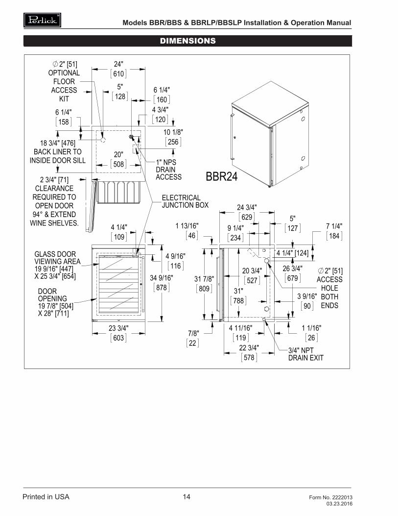
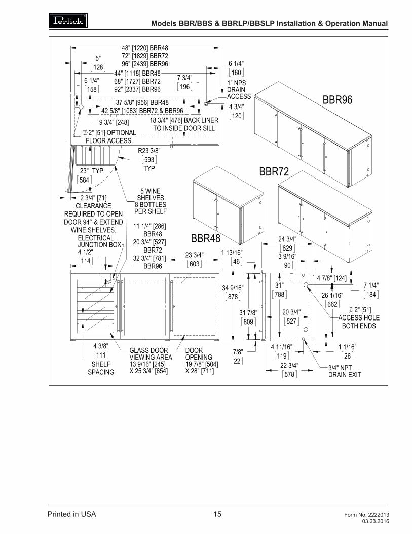
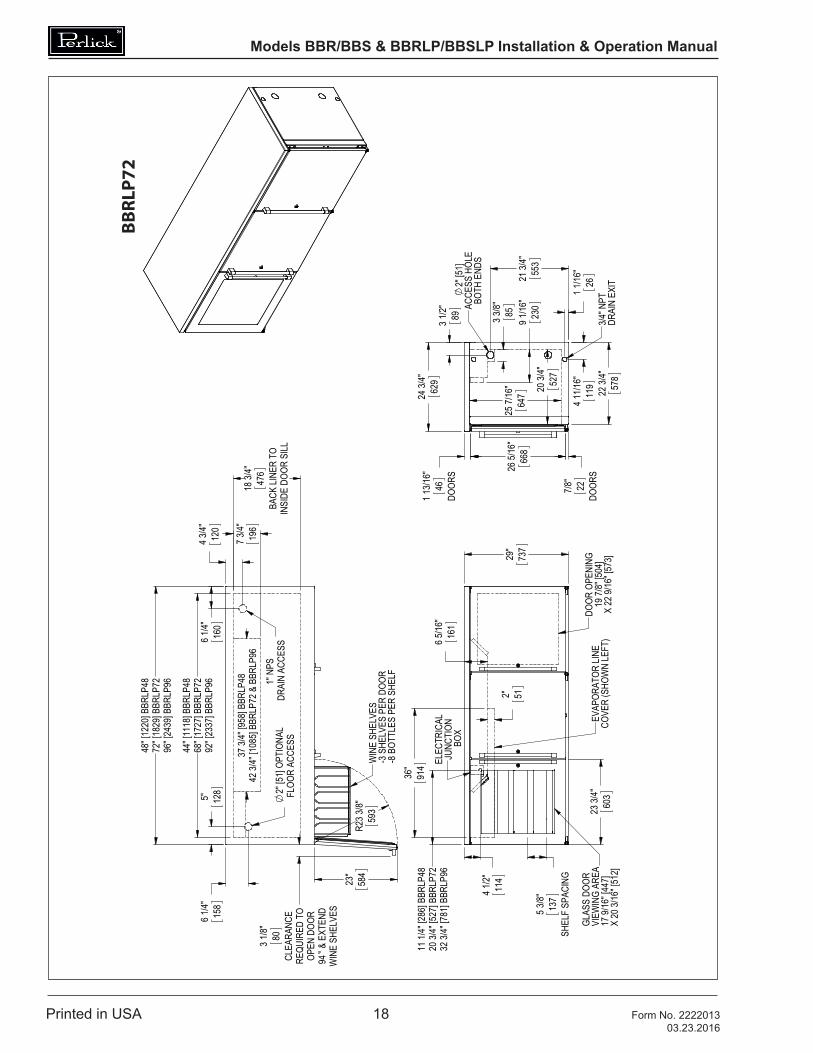
1. Make sure the space opening is correctly sized for the unit. See Dimension drawings at the back of this manual for correct dimensions.
NOTE: For a cabinet door to open properly, the door must open a minimum of 90°. Use a minimum 3” filler in corner installations to assure a 90° opening. Allow 24” clearance in front of the unit for full door swing and shelf/drawer pull-out.
2. Check that the following are level and square:• Front and interior opening• Installation opening and floor surface
NOTE: The floor under the unit must be at the same level as the surrounding finished floor.
Casters or LegsRefer to the instructions included with the Casters or Legs Kit.
Installing the Unit
CAUTION If unit has been laid on its back or sides, place unit
upright and allow minimum of 24 hours before connecting power.1. With power applied to the unit, check that
the lighting and cooling functions operate properly, then turn off power to the wall outlet and/or circuit breaker.
2. Position the cabinet into place using rollers when necessary.
NOTE: Proper air flow around the condensing unit is necessary for efficient operation. Never obstruct the air flow in and out of the condensing unit.
3. When cabinet is in place, check installation with carpenter’s level. When the unit is level front-to-back and side-to-side, accumulated water will drain out of cabinet to evaporator drain.
4. Turn on power to the outlet and/or circuit breaker.
Electric Condensate Evapaway (Optional)For installation in areas of high humidity, a 115-volt electric condensate pan can be installed underneath the cabinet to collect and evaporate the condensate from the cabinet evaporator. A 6’ 3-prong plug is included. A separate circuit should be provided for the heater. The kit can be used only on cabinets equipped with 4” minimum legs; it cannot be used on units equipped with platform or base plate kits. Follow instructions supplied with the kit.
Base Plate Installation (Optional)Once the unit is secured in place, install the base plate brackets to the cabinet bottom in the holes provided. Attach base plate to brackets. Refer to the installation instructions included with the Base Plate Kit.
Models BBR/BBS & BBRLP/BBSLP Installation & Operation Manual
Printed in USA 5 Form No. 222201303.23.2016
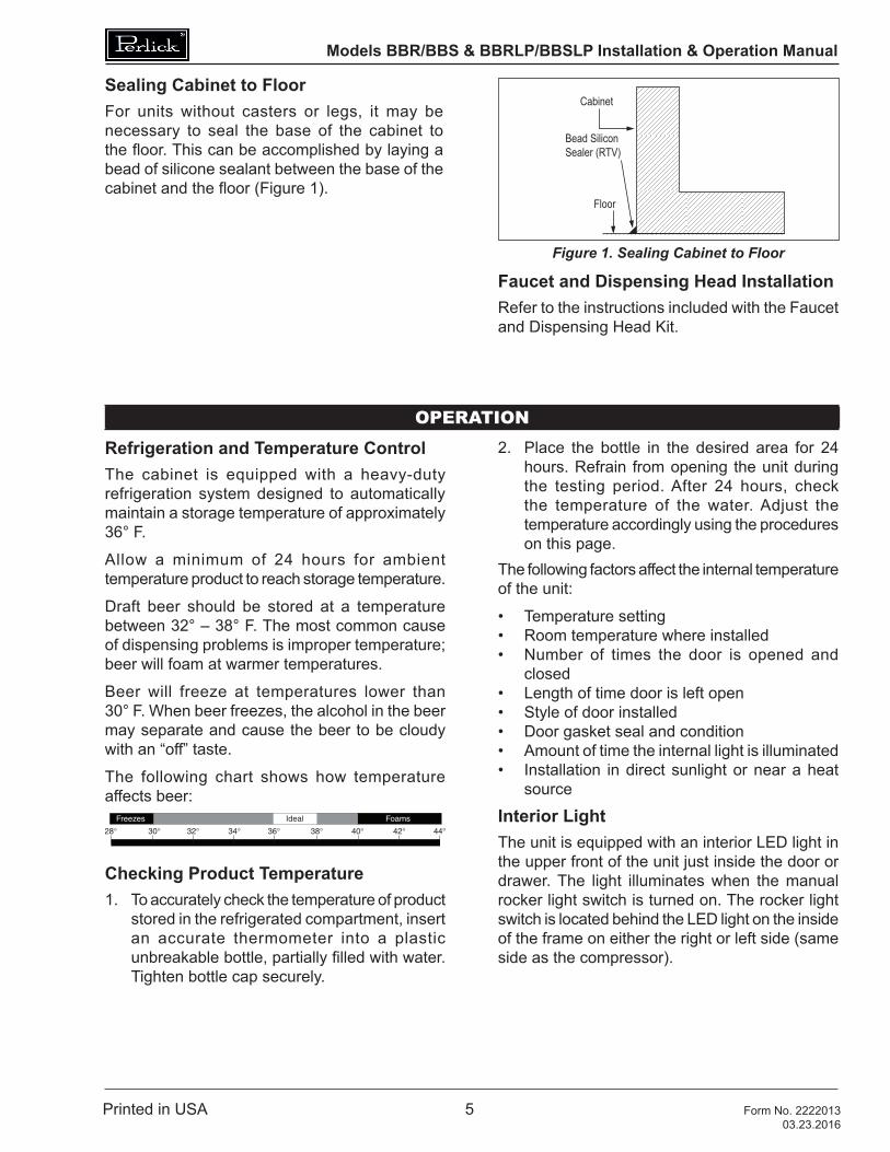
Sealing Cabinet to FloorFor units without casters or legs, it may be necessary to seal the base of the cabinet to the floor. This can be accomplished by laying a bead of silicone sealant between the base of the cabinet and the floor (Figure 1).
Cabinet
Bead SiliconSealer (RTV)
Floor
Figure 1. Sealing Cabinet to Floor
Faucet and Dispensing Head InstallationRefer to the instructions included with the Faucet and Dispensing Head Kit.
OPERATION
Refrigeration and Temperature ControlThe cabinet is equipped with a heavy-duty refrigeration system designed to automatically maintain a storage temperature of approximately 36° F.
Allow a minimum of 24 hours for ambient temperature product to reach storage temperature.
Draft beer should be stored at a temperature between 32° – 38° F. The most common cause of dispensing problems is improper temperature; beer will foam at warmer temperatures.
Beer will freeze at temperatures lower than 30° F. When beer freezes, the alcohol in the beer may separate and cause the beer to be cloudy with an “off” taste.
The following chart shows how temperature affects beer:
Checking Product Temperature1. To accurately check the temperature of product
stored in the refrigerated compartment, insert an accurate thermometer into a plastic unbreakable bottle, partially filled with water. Tighten bottle cap securely.
2. Place the bottle in the desired area for 24 hours. Refrain from opening the unit during the testing period. After 24 hours, check the temperature of the water. Adjust the temperature accordingly using the procedures on this page.
The following factors affect the internal temperature of the unit:
• Temperature setting• Room temperature where installed• Number of times the door is opened and
closed• Length of time door is left open• Style of door installed• Door gasket seal and condition• Amount of time the internal light is illuminated• Installation in direct sunlight or near a heat
source
Interior LightThe unit is equipped with an interior LED light in the upper front of the unit just inside the door or drawer. The light illuminates when the manual rocker light switch is turned on. The rocker light switch is located behind the LED light on the inside of the frame on either the right or left side (same side as the compressor).
Models BBR/BBS & BBRLP/BBSLP Installation & Operation Manual
Printed in USA 6 Form No. 222201303.23.2016
Digital Temperature Control
SET
F�
Figure 2. Digital Temperature Controller
To change the Setpoint:
1. Press the SET button for more than 2 seconds.2. The value of the setpoint will be displayed and
the “C” or “F” LED starts blinking.3. To change the Set value, press the
or button within 10 seconds.4. To memorize the new setpoint value, press
the SET key again, or wait 10 seconds.
ADJUSTMENTS
Changing Door Swing DirectionNOTE: Changing the door swing direction is not advisable if the door is not equipped with a full length handle. Doing so may result in an undesirable handle position..Hinge Kits
Part No. 67439R: Right Hinging
Part No. 67439L: Left HingingTools Required
• Large flat head screwdriver
• Regular Phillips head screwdriver
• Hinge Kit from Perlick
• Plastic putty knifeProcedure
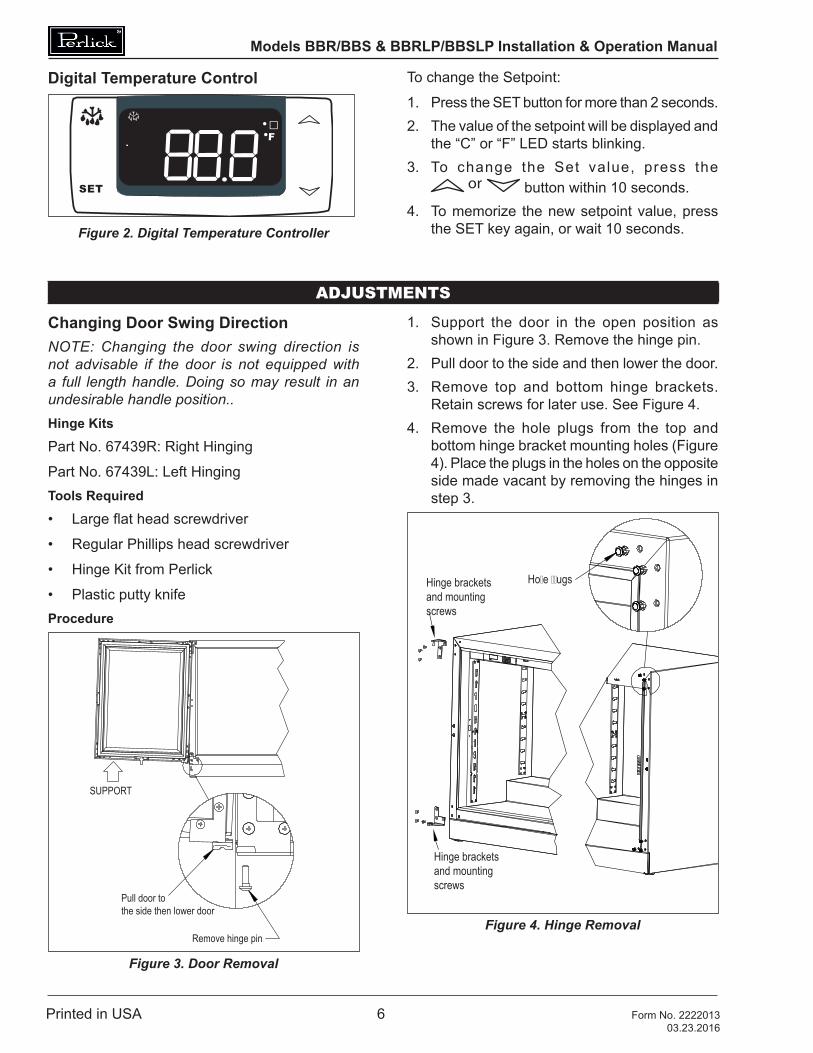
SUPPORT
Pull door to the side then lower door
Remove hinge pin
Figure 3. Door Removal
1. Support the door in the open position as shown in Figure 3. Remove the hinge pin.
2. Pull door to the side and then lower the door.3. Remove top and bottom hinge brackets.
Retain screws for later use. See Figure 4.4. Remove the hole plugs from the top and
bottom hinge bracket mounting holes (Figure 4). Place the plugs in the holes on the opposite side made vacant by removing the hinges in step 3.
Hinge bracketsand mounting screws
Hinge bracketsand mounting screws
Ho�e ��ugs
Figure 4. Hinge Removal
Models BBR/BBS & BBRLP/BBSLP Installation & Operation Manual
Printed in USA 7 Form No. 222201303.23.2016
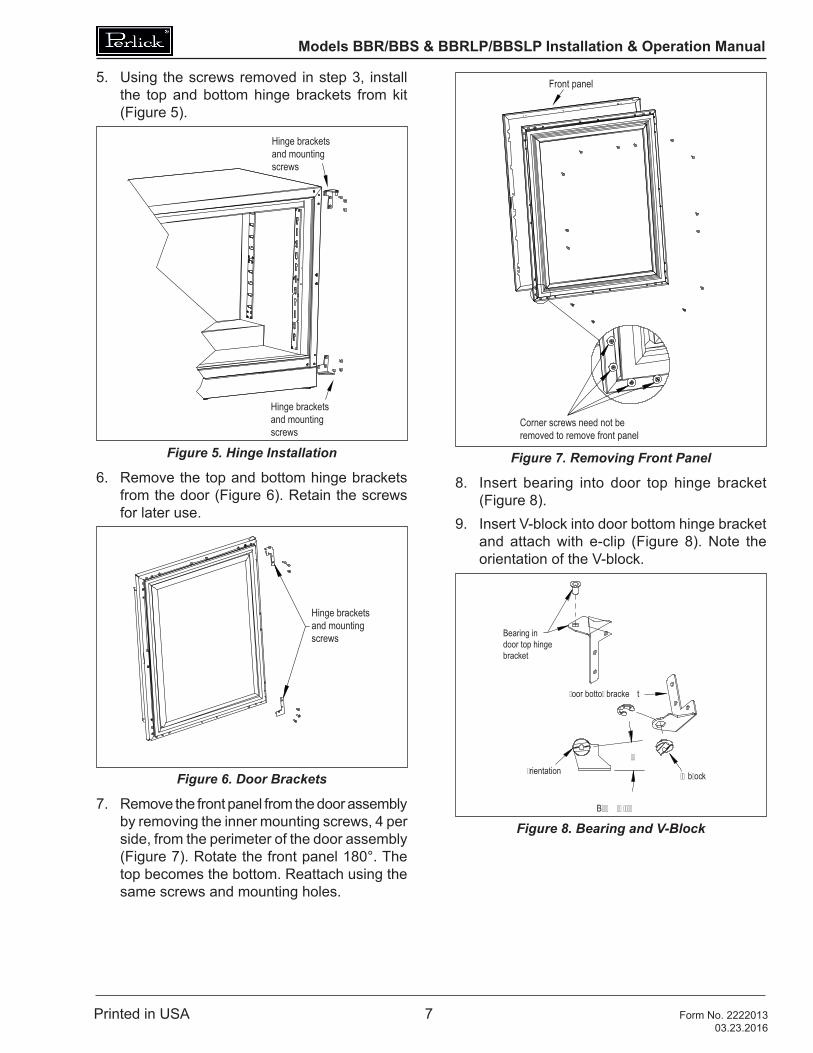
5. Using the screws removed in step 3, install the top and bottom hinge brackets from kit (Figure 5).
Hinge bracketsand mounting screws
Hinge bracketsand mounting screws
Figure 5. Hinge Installation
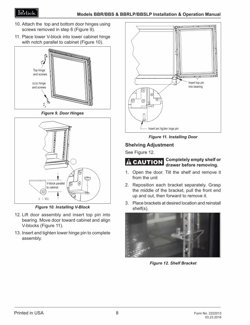
6. Remove the top and bottom hinge brackets from the door (Figure 6). Retain the screws for later use.
Hinge bracketsand mounting screws
Figure 6. Door Brackets
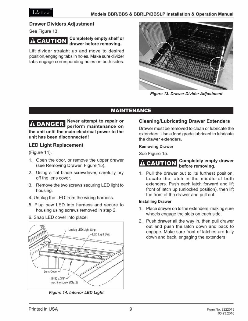
7. Remove the front panel from the door assembly by removing the inner mounting screws, 4 per side, from the perimeter of the door assembly (Figure 7). Rotate the front panel 180°. The top becomes the bottom. Reattach using the same screws and mounting holes.
Front panel
Corner screws need not be removed to remove front panel
Figure 7. Removing Front Panel
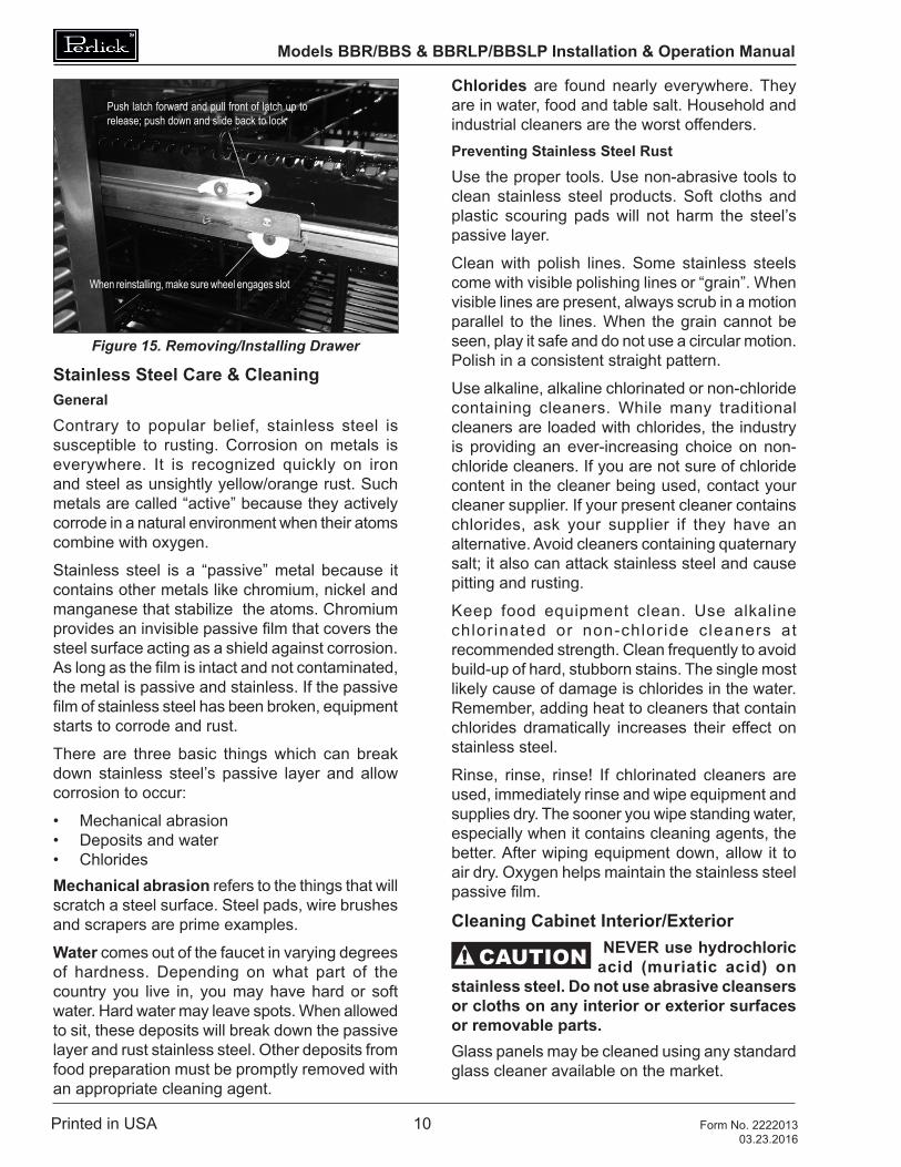
8. Insert bearing into door top hinge bracket (Figure 8).
9. Insert V-block into door bottom hinge bracket and attach with e-clip (Figure 8). Note the orientation of the V-block.
Bearing indoor top hingebracket
�oor botto� bracke t
�� b�ock
��
B��� �� ����
�rientation
Figure 8. Bearing and V-Block
Models BBR/BBS & BBRLP/BBSLP Installation & Operation Manual
Printed in USA 8 Form No. 222201303.23.2016
Insert top pininto bearing
Insert an� tig�ten �inge pin
Figure 11. Installing Door
Shelving Adjustment See Figure 12.
CAUTION Completely empty shelf or drawer before removing.
1. Open the door. Tilt the shelf and remove it from the unit
2. Reposition each bracket separately. Grasp the middle of the bracket, pull the front end up and out, then forward to remove it.
3. Place brackets at desired location and reinstall shelf(s).
Figure 12. Shelf Bracket
10. Attach the top and bottom door hinges using screws removed in step 6 (Figure 9).
11. Place lower V-block into lower cabinet hinge with notch parallel to cabinet (Figure 10).
Top hingeand screws
�o��o� hingeand screws
Figure 9. Door Hinges
V-block parallelto cabinet
�� � V���
Figure 10. Installing V-Block
12. Lift door assembly and insert top pin into bearing. Move door toward cabinet and align V-blocks (Figure 11).
13. Insert and tighten lower hinge pin to complete assembly.
Models BBR/BBS & BBRLP/BBSLP Installation & Operation Manual
Printed in USA 9 Form No. 222201303.23.2016
Drawer Dividers AdjustmentSee Figure 13.
CAUTION Completely empty shelf or drawer before removing.
Lift divider straight up and move to desired position,engaging tabs in holes. Make sure divider tabs engage corresponding holes on both sides.
Figure 13. Drawer Divider Adjustment
MAINTENANCE
DANGER Never attempt to repair or perform maintenance on
the unit until the main electrical power to the unit has been disconnected!
LED Light Replacement(Figure 14).
1. Open the door, or remove the upper drawer (see Removing Drawer, Figure 15).
2. Using a flat blade screwdriver, carefully pry off the lens cover.
3. Remove the two screws securing LED light to housing.
4. Unplug the LED from the wiring harness.5. Plug new LED into harness and secure to
housing using screws removed in step 2.6. Snap LED cover into place.
#6-32 x 3/8”machine screw (Qty. 2)
Lens Cover
Unplug LED Light StripLED Light Strip
Figure 14. Interior LED Light
Cleaning/Lubricating Drawer ExtendersDrawer must be removed to clean or lubricate the extenders. Use a food grade lubricant to lubricate the drawer extenders.Removing Drawer
See Figure 15.
CAUTION Completely empty drawer before removing.
1. Pull the drawer out to its furthest position. Locate the latch in the middle of both extenders. Push each latch forward and lift front of latch up (unlocked position), then lift the front of the drawer and pull out.
Installing Drawer
1. Place drawer on to the extenders, making sure wheels engage the slots on each side.
2. Push drawer all the way in, then pull drawer out and push the latch down and back to engage. Make sure front of latches are fully down and back, engaging the extenders.
Models BBR/BBS & BBRLP/BBSLP Installation & Operation Manual
Printed in USA 10 Form No. 222201303.23.2016
Push latch forward and pull front of latch up to release; push down and slide back to lock
When reinstalling, make sure wheel engages slot
Figure 15. Removing/Installing Drawer
Stainless Steel Care & CleaningGeneral
Contrary to popular belief, stainless steel is susceptible to rusting. Corrosion on metals is everywhere. It is recognized quickly on iron and steel as unsightly yellow/orange rust. Such metals are called “active” because they actively corrode in a natural environment when their atoms combine with oxygen.
Stainless steel is a “passive” metal because it contains other metals like chromium, nickel and manganese that stabilize the atoms. Chromium provides an invisible passive film that covers the steel surface acting as a shield against corrosion. As long as the film is intact and not contaminated, the metal is passive and stainless. If the passive film of stainless steel has been broken, equipment starts to corrode and rust.
There are three basic things which can break down stainless steel’s passive layer and allow corrosion to occur:
• Mechanical abrasion• Deposits and water• ChloridesMechanical abrasion refers to the things that will scratch a steel surface. Steel pads, wire brushes and scrapers are prime examples.
Water comes out of the faucet in varying degrees of hardness. Depending on what part of the country you live in, you may have hard or soft water. Hard water may leave spots. When allowed to sit, these deposits will break down the passive layer and rust stainless steel. Other deposits from food preparation must be promptly removed with an appropriate cleaning agent.
Chlorides are found nearly everywhere. They are in water, food and table salt. Household and industrial cleaners are the worst offenders.Preventing Stainless Steel Rust
Use the proper tools. Use non-abrasive tools to clean stainless steel products. Soft cloths and plastic scouring pads will not harm the steel’s passive layer.
Clean with polish lines. Some stainless steels come with visible polishing lines or “grain”. When visible lines are present, always scrub in a motion parallel to the lines. When the grain cannot be seen, play it safe and do not use a circular motion. Polish in a consistent straight pattern.
Use alkaline, alkaline chlorinated or non-chloride containing cleaners. While many traditional cleaners are loaded with chlorides, the industry is providing an ever-increasing choice on non-chloride cleaners. If you are not sure of chloride content in the cleaner being used, contact your cleaner supplier. If your present cleaner contains chlorides, ask your supplier if they have an alternative. Avoid cleaners containing quaternary salt; it also can attack stainless steel and cause pitting and rusting.
Keep food equipment clean. Use alkaline chlor inated or non-chlor ide cleaners at recommended strength. Clean frequently to avoid build-up of hard, stubborn stains. The single most likely cause of damage is chlorides in the water. Remember, adding heat to cleaners that contain chlorides dramatically increases their effect on stainless steel.
Rinse, rinse, rinse! If chlorinated cleaners are used, immediately rinse and wipe equipment and supplies dry. The sooner you wipe standing water, especially when it contains cleaning agents, the better. After wiping equipment down, allow it to air dry. Oxygen helps maintain the stainless steel passive film.
Cleaning Cabinet Interior/Exterior
CAUTION NEVER use hydrochloric acid (muriatic acid) on
stainless steel. Do not use abrasive cleansers or cloths on any interior or exterior surfaces or removable parts.Glass panels may be cleaned using any standard glass cleaner available on the market.
Models BBR/BBS & BBRLP/BBSLP Installation & Operation Manual
Printed in USA 11 Form No. 222201303.23.2016
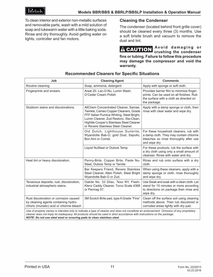
To clean interior and exterior non-metallic surfaces and removable parts, wash with a mild solution of soap and lukewarm water with a little baking soda. Rinse and dry thoroughly. Avoid getting water on lights, controller and fan motors.
Cleaning the CondenserThe condenser (located behind front grille cover) should be cleaned every three (3) months. Use a soft bristle brush and vacuum to remove the dust and lint.
CAUTION Av o i d d a m a g i n g o r crushing the condenser
fins or tubing. Failure to follow this procedure may damage the compressor and void the warranty.
Recommended Cleaners for Specific SituationsJob Cleaning Agent Comments
Routine cleaning. Soap, ammonia, detergent Apply with sponge or soft cloth.Fingerprints and smears. Areal 20, Lac-O-Nu, Lumin Wash,
O’Ceder Cream PolishProvides barrier film to minimize finger-prints. Can be used on all finishes. Rub the surface with a cloth as directed on the package.
Stubborn stains and discolorations. AllChem Concentrated Cleaner, Samae, Twinkle, Cameo Copper Cleaners, Grade FFF Italian Pumice Whiting, Steel Bright, Lumin Cleaner, Zud Restoro, Sta-Clean, Highlite Cooper’s Stainless Steel Cleaner or Revere Stainless Steel Cleaner.
Apply with a damp sponge or cloth, then rinse with clear water and wipe dry.
Old Dutch, Lighthouse Sunbri te, Wyandotte Bab-O, gold Dust, Sapollo, Bon Ami or Comet.
For these household cleaners, rub with a damp cloth. They may contain chlorine bleaches so rinse thoroughly after use and wipe dry
Liquid NuSteel or Dubois Temp For these products, rub the surface with a dry cloth using only a small amount of cleanser. Rinse with water and dry.
Heat tint or heavy discoloration. Penny-Brite, Copper Brite, Paste Nu-Steel, Dubois Temp or Tarnite
Rinse and rub onto surface with a dry cloth.
Bar Keepers Friend, Revere Stainless Steel Cleaner, Allen Polish, Steel Bright Wyandotte Bab-O or Zud.
When using these cleaners, apply with a damp sponge or cloth, rinse thoroughly and wipe dry.
Tenacious deposits, rust, discoloration, industrial atmospheric stains.
Oakite No. 33 Dilac, Texo NY, Flash-Klenz Caddy Cleaner, Turco Scale 4368 or Permag 57.
Use Swab and soak with a clean cloth. Let stand for 15 minutes or more according to directions on package then rinse and wipe dry.
Rust discoloration or corrosion caused by cleaning agents containing hydro-chloric (muriatic) acid or chlorine bleach
3M Scotch Brite pad, type A Grade “Fine” Clean off the surface soil using cleaning methods above. Then rub discolored or corroded areas lightly with dry pad.
Use of property names is intended only to indicate a type of cleaner and does not constitute an endorsement. Omission of any proprietary cleaner does not imply its inadequacy. All products should be used in strict accordance with instructions on the package. NOTE: Do not use steel wool or scouring pads to clean stainless steel.
Models BBR/BBS & BBRLP/BBSLP Installation & Operation Manual
Printed in USA 12 Form No. 222201303.23.2016
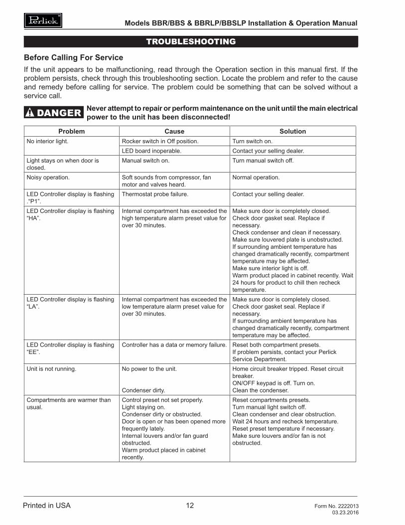
TROUBLESHOOTING
Before Calling For ServiceIf the unit appears to be malfunctioning, read through the Operation section in this manual first. If the problem persists, check through this troubleshooting section. Locate the problem and refer to the cause and remedy before calling for service. The problem could be something that can be solved without a service call.
DANGER Never attempt to repair or perform maintenance on the unit until the main electrical power to the unit has been disconnected!
Problem Cause SolutionNo interior light. Rocker switch in Off position. Turn switch on.
LED board inoperable. Contact your selling dealer.Light stays on when door is closed.
Manual switch on. Turn manual switch off.
Noisy operation. Soft sounds from compressor, fan motor and valves heard.
Normal operation.
LED Controller display is flashing .“P1”.
Thermostat probe failure. Contact your selling dealer.
LED Controller display is flashing “HA”.
Internal compartment has exceeded the high temperature alarm preset value for over 30 minutes.
Make sure door is completely closed.Check door gasket seal. Replace if necessary. Check condenser and clean if necessary.Make sure louvered plate is unobstructed.If surrounding ambient temperature has changed dramatically recently, compartment temperature may be affected.Make sure interior light is off.Warm product placed in cabinet recently. Wait 24 hours for product to chill then recheck temperature.
LED Controller display is flashing “LA”.
Internal compartment has exceeded the low temperature alarm preset value for over 30 minutes.
Make sure door is completely closed.Check door gasket seal. Replace if necessary.If surrounding ambient temperature has changed dramatically recently, compartment temperature may be affected.
LED Controller display is flashing “EE”.
Controller has a data or memory failure. Reset both compartment presets.If problem persists, contact your Perlick Service Department.
Unit is not running. No power to the unit.
Condenser dirty.
Home circuit breaker tripped. Reset circuit breaker.ON/OFF keypad is off. Turn on.Clean the condenser.
Compartments are warmer than usual.
Control preset not set properly.Light staying on.Condenser dirty or obstructed.Door is open or has been opened more frequently lately.Internal louvers and/or fan guard obstructed.Warm product placed in cabinet recently.
Reset compartments presets.Turn manual light switch off.Clean condenser and clear obstruction.Wait 24 hours and recheck temperature. Reset preset temperature if necessary.Make sure louvers and/or fan is not obstructed.
Models BBR/BBS & BBRLP/BBSLP Installation & Operation Manual
Printed in USA 13 Form No. 222201303.23.2016
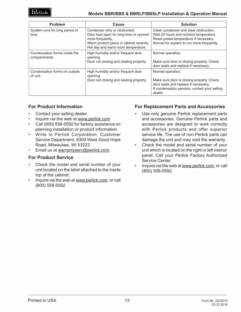
Problem Cause SolutionSystem runs for long period of time.
Condenser dirty or obstructed.Door kept open for long time or opened more frequently.Warm product place in cabinet recently.Hot day and warm room temperature.
Clean condenser and clear obstruction.Wait 24 hours and recheck temperature. Reset preset temperature if necessary.Normal for system to run more frequently.
Condensation forms inside the compartments.
High humidity and/or frequent door opening.Door not closing and sealing properly.
Normal operation.
Make sure door is closing properly. Check door seals and replace if necessary.
Condensation forms on outside of unit.
High humidity and/or frequent door opening.Door not closing and sealing properly.
Normal operation.
Make sure door is closing properly. Check door seals and replace if necessary.If condensation persists, contact your selling dealer.
For Product Information• Contact your selling dealer.• Inquire via the web at www.perlick.com• Call (800) 558-5592 for factory assistance on
planning installation or product information.• Write to Perlick Corporation, Customer
Service Department, 8300 West Good Hope Road, Milwaukee, WI 53223.
• Email us at [email protected].
For Product Service• Check the model and serial number of your
unit located on the label attached to the inside top of the cabinet.
• Inquire via the web at www.perlick.com, or call (800) 558-5592.
For Replacement Parts and Accessories• Use only genuine Perlick replacement parts
and accessories. Genuine Perlick parts and accessories are designed to work correctly with Perlick products and offer superior service life. The use of non-Perlick parts can damage the unit and may void the warranty.
• Check the model and serial number of your unit which is located on the right or left interior panel. Call your Perlick Factory Authorized Service Center.
• Inquire via the web at www.perlick.com, or call (800) 558-5592.
Models BBR/BBS & BBRLP/BBSLP Installation & Operation Manual
Printed in USA 14 Form No. 222201303.23.2016
DIMENSIONS
Models BBR/BBS & BBRLP/BBSLP Installation & Operation Manual
Printed in USA 15 Form No. 222201303.23.2016
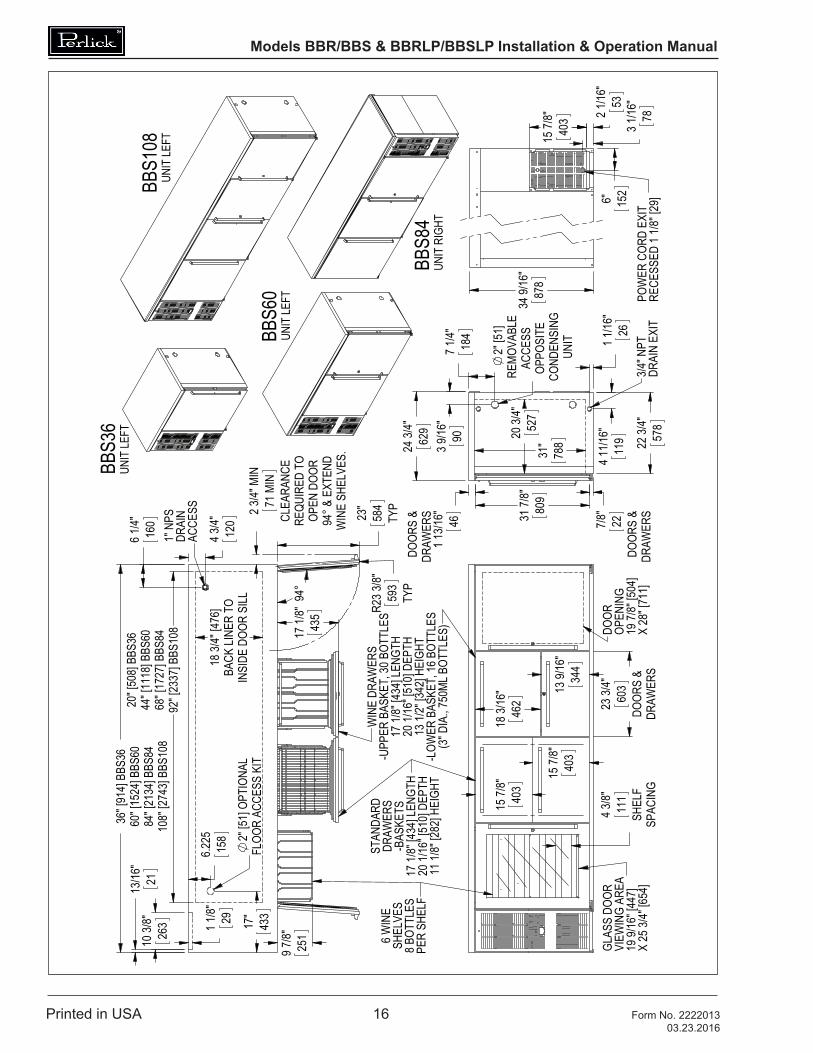
Models BBR/BBS & BBRLP/BBSLP Installation & Operation Manual
Printed in USA 16 Form No. 222201303.23.2016
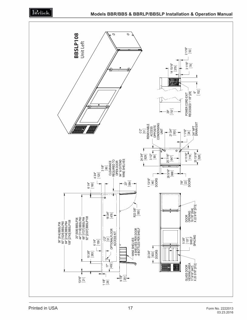
Models BBR/BBS & BBRLP/BBSLP Installation & Operation Manual
Printed in USA 17 Form No. 222201303.23.2016
REVI
SION
S
THIS
DO
CUM
ENT
/ PU
BLIC
ATIO
N /
SO
FTW
ARE
/ D
RAW
ING
CO
NTA
INS
PRO
PRIE
TARY
IN
FORM
ATIO
N W
HIC
H I
S TH
E PR
OPE
RTY
OF
THE
PERL
ICK
CORP
ORA
TIO
N. I
T M
AY N
OT
BE R
EPRO
DU
CED
OR
TRAN
SMIT
TED
IN
AN
Y FO
RM, E
LECT
RON
IC O
R M
ECH
ANIC
AL, I
NCL
UD
ING
PH
OTO
COPY
ING
, REC
ORD
ING
, OR
USE
D I
N A
NY
INFO
RMAT
ION
STO
RAG
E, T
RAN
SMIS
SIO
N, O
R RE
TRIE
VAL
SYST
EM, W
ITH
OU
T W
RITT
EN P
ERM
ISSI
ON
FRO
M T
HE
PERL
ICK
CORP
ORA
TIO
N. C
OPY
RIG
HT
2001
PER
LICK
CO
RPO
RATI
ON
. ALL
RIG
HTS
RES
ERVE
D.
DESI
GNED
DRAW
N
FINIS
H:
QTY.
:
.012
HOLE
S:
.0135
THR
U .12
5: .00
4
.12
60 T
HRU
.250:
.005
.2510
THR
U .50
0: .00
6
.50
10 T
HRU
.750:
.008
.7510
THR
U 1.0
00:
.010
1.001
& U
P:
BREA
K SH
ARP
EDGE
S - .
015 X
45°
RADI
US S
HARP
FILL
ETS
- .01
5 TO
.031
UNLE
SS O
THER
WIS
E SP
ECIF
IED:
TITL
E:
PURC
HASE
REC
.:
PART
NO.
REFE
RENC
E:DW
G NO
.
MATE
RIAL
:P
erlic
k C
orpo
rati
onDA
TESI
GNAT
URES
Milw
auke
e, W
isco
nsin
20 13
/16"
528
25 7/
16"
647
R23 3
/8"59
3
23
"58
4
10 3/
8"26
3
13/16
"21
1 1/8
"29
2"
OPTI
ONAL
FLOO
R AC
CESS
KIT
51
6 1/
4"15
9
17
"43
2
18 3/
4"47
6
20" [
508]
BBSL
P36
44" [
1118
] BBS
LP60
68" [
1727
] BBS
LP84
92" [
2337
] BBS
LP10
8
3/4" N
PTDR
AIN
EXIT
26
5/16
"66
8
UNIT
COND
ENSI
NGOP
POSI
TEAC
CESS
REMO
VABL
E51
893 1
/2"
21 3/
4"
553
2" 1 1
/16"
26
119
4 11/1
6"
62
924
3/4"
DOOR
S
1 13/1
6"46
7/8
"22
DOOR
S
RELE
ASE
FOR
PROD
UCTI
ON
2
2
B A
3
C
B A
1
C
13
ANG
ULAR
: , F
RACT
IONS
:
SW
J:\D
wg\
9500
0\95
318.
sldd
rw
SCAL
E = 1
:24
2/23/2
016
JMP
LOW
HEI
GH
T SC
BAC
K BA
RCU
TSH
EET
DIM
ENSI
ON
S
N/A
9531
8
A2/2
5/201
6
SHEE
T 1 O
F 2
DIME
NSIO
NS A
RE IN
INCH
ESTO
LERA
NCES
: .X
= ,
.XX
= ,
.XXX
= ,
JMP
78RE
CESS
ED 1
1/8" [
29]
POW
ER C
ORD
EXIT
3 1/16
"
14 15
/16"
379
2 1
/16"
536"
15
2
29
"73
7
GLAS
S DO
ORVI
EWIN
G AR
EA17
9/16
" [44
7]X
20 3/
16" [
512]
DOOR
OPEN
ING
19 7/
8" [5
04]
X 22
9/16
" [57
3]
23 3/
4"60
3DO
ORS
5 3/8"
137
SHEL
FSP
ACIN
G
WIN
E SH
ELVE
S-4
SHE
LVES
PER
DOO
R-8
BOT
TLES
PER
SHE
LF
36" [
914]
BBSL
P36
60" [
1524
] BBS
LP60
6 1/
4"
84" [
2134
] BBS
LP84
108"
[274
3] BB
SLP1
08
WIN
E SH
ELVE
S &
EXT
END
94OPEN
DOO
RRE
QUIR
ED T
OCL
EARA
NCE
80
4 3
/4"12
0
16
0
3 1/8"
9 7/
8"25
1
2/25
/201
6 11
:27
AM
BBSL
P108
Uni
t Lef
t
Models BBR/BBS & BBRLP/BBSLP Installation & Operation Manual
Printed in USA 18 Form No. 222201303.23.2016
REVI
SION
S
THIS
DO
CUM
ENT
/ PU
BLIC
ATIO
N /
SO
FTW
ARE
/ D
RAW
ING
CO
NTA
INS
PRO
PRIE
TARY
IN
FORM
ATIO
N W
HIC
H I
S TH
E PR
OPE
RTY
OF
THE
PERL
ICK
CORP
ORA
TIO
N. I
T M
AY N
OT
BE R
EPRO
DU
CED
OR
TRAN
SMIT
TED
IN
AN
Y FO
RM, E
LECT
RON
IC O
R M
ECH
ANIC
AL, I
NCL
UD
ING
PH
OTO
COPY
ING
, REC
ORD
ING
, OR
USE
D I
N A
NY
INFO
RMAT
ION
STO
RAG
E, T
RAN
SMIS
SIO
N, O
R RE
TRIE
VAL
SYST
EM, W
ITH
OU
T W
RITT
EN P
ERM
ISSI
ON
FRO
M T
HE
PERL
ICK
CORP
ORA
TIO
N. C
OPY
RIG
HT
2001
PER
LICK
CO
RPO
RATI
ON
. ALL
RIG
HTS
RES
ERVE
D.
DESI
GNED
DRAW
N
FINIS
H:
QTY.
:
.012
HOLE
S:
.0135
THR
U .12
5: .00
4
.12
60 T
HRU
.250:
.005
.2510
THR
U .50
0: .00
6
.50
10 T
HRU
.750:
.008
.7510
THR
U 1.0
00:
.010
1.001
& U
P:
BREA
K SH
ARP
EDGE
S - .
015 X
45°
RADI
US S
HARP
FILL
ETS
- .01
5 TO
.031
UNLE
SS O
THER
WIS
E SP
ECIF
IED:
TITL
E:
PURC
HASE
REC
.:
PART
NO.
REFE
RENC
E:DW
G NO
.
MATE
RIAL
:P
erlic
k C
orpo
rati
onDA
TESI
GNAT
URES
Milw
auke
e, W
isco
nsin
11 1/
4" [2
86] B
BRLP
4820
3/4"
[527
] BBR
LP72
32 3/
4" [7
81] B
BRLP
96
4 1/
2"11
4
6 5/1
6"16
1
2" 51
36
"91
4
23
"58
4
R23 3
/8"59
3
2" [5
1] OP
TION
ALFL
OOR
ACCE
SS
37 3/
4" [9
58] B
BRLP
4842
3/4"
[108
5] BB
RLP7
2 & B
BRLP
9618
3/4"
476
BACK
LINE
R TO
INSI
DE D
OOR
SILL
7 3/
4"19
6
1" N
PS
DRAI
N AC
CESS
4 3/
4"12
0
6 1/
4"16
0
5" 12
8
6 1/
4"15
8
44" [
1118
] BBR
LP48
68" [
1727
] BBR
LP72
92" [
2337
] BBR
LP96
25 7/
16"
647
20 3/
4"52
7
9 1/1
6"23
0
3 3/8
"85
RELE
ASE
FOR
PROD
UCTI
ON
2
2
B A
3
C
B A
1
C
13
ANG
ULAR
: , F
RACT
IONS
:
SW
J:\D
wg\
9500
0\95
318.
sldd
rw
SCAL
E = 1
:16
2/25/2
016
JMP
LOW
HEI
GH
T RE
MO
TE B
ACK
BAR
CUTS
HEE
T D
IMEN
SIO
NS
N/A
9531
8
A2/2
5/201
6
SHEE
T 2 O
F 2
DIME
NSIO
NS A
RE IN
INCH
ESTO
LERA
NCES
: .X
= ,
.XX
= ,
.XXX
= ,
JMP
ELEC
TRIC
AL
EVAP
ORAT
OR LI
NECO
VER
(SHO
WN
LEFT
)X
20 3/
16" [
512]
17 9/
16" [
447]
VIEW
ING
AREA
BOX
JUNC
TION
GLAS
S DO
ORDO
OR O
PENI
NG19
7/8"
[504
]X
22 9/
16" [
573]
23 3/
4"60
3
SHEL
F SP
ACIN
G
5 3/8"
137
29
"73
7
WIN
E SH
ELVE
S-3
SHE
LVES
PER
DOO
R-8
BOT
TLES
PER
SHE
LF
& E
XTEN
DW
INE
SHEL
VES
94
3 1/8" 80
CLEA
RANC
ERE
QUIR
ED T
OOP
EN D
OOR
48" [
1220
] BBR
LP48
72" [
1829
] BBR
LP72
96" [
2439
] BBR
LP96
DRAI
N EX
IT3/4
" NPT
2" [5
1]AC
CESS
HOL
EBO
TH E
NDS
26 5/
16"
66
8
4 11/1
6"
119
1 1/16
"26
DOOR
S
7/8"
22
3 1/2
"89
DO
ORS
1 13/1
6"46
55
321
3/4"
62
924
3/4"
22 3/
4"57
8
2/25
/201
6 11
:27
AM
BBRL
P72
Models BBR/BBS & BBRLP/BBSLP Installation & Operation Manual
Printed in USA 19 Form No. 222201303.23.2016
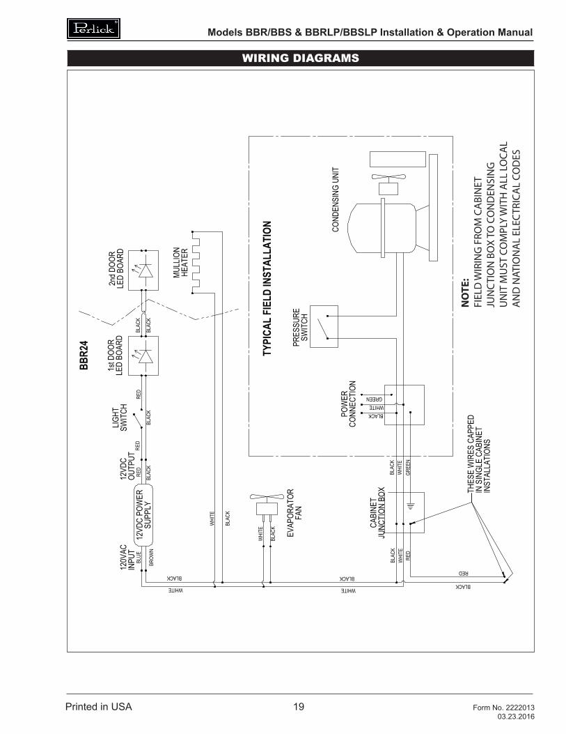
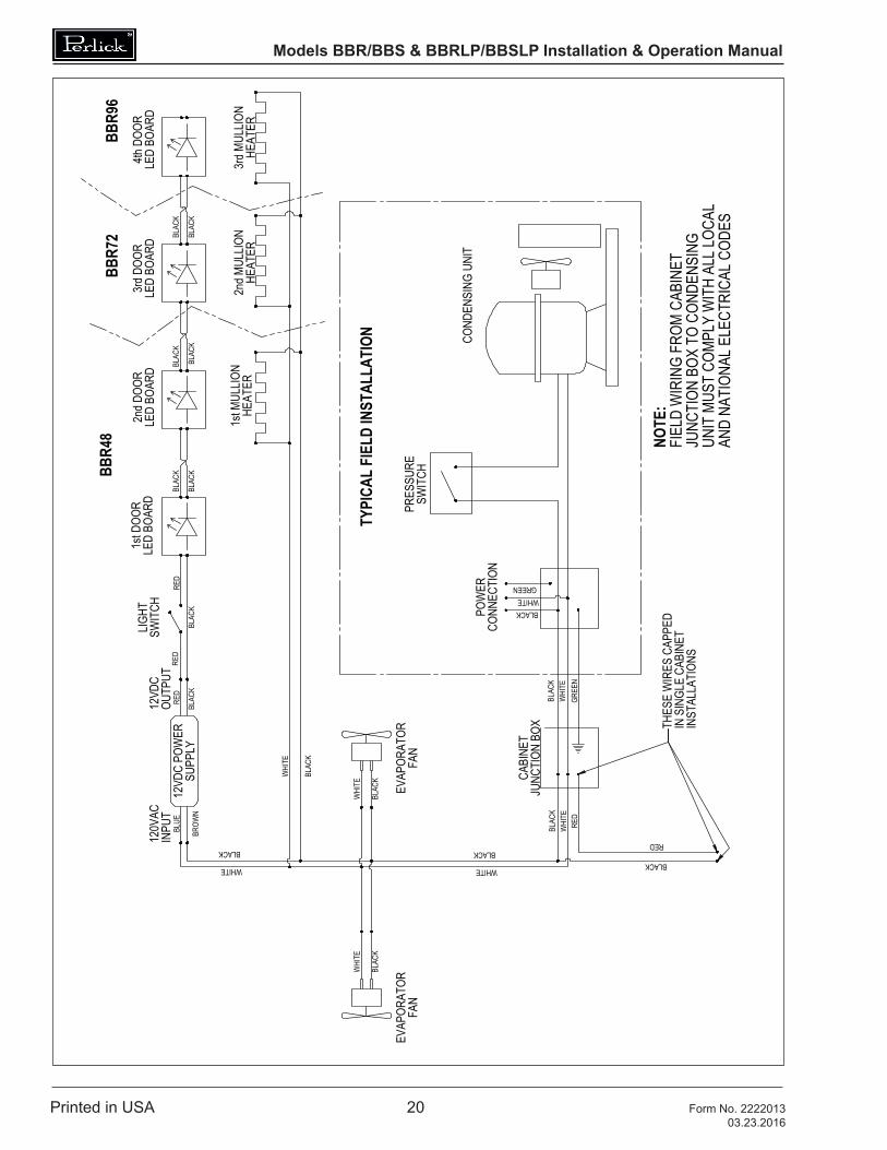
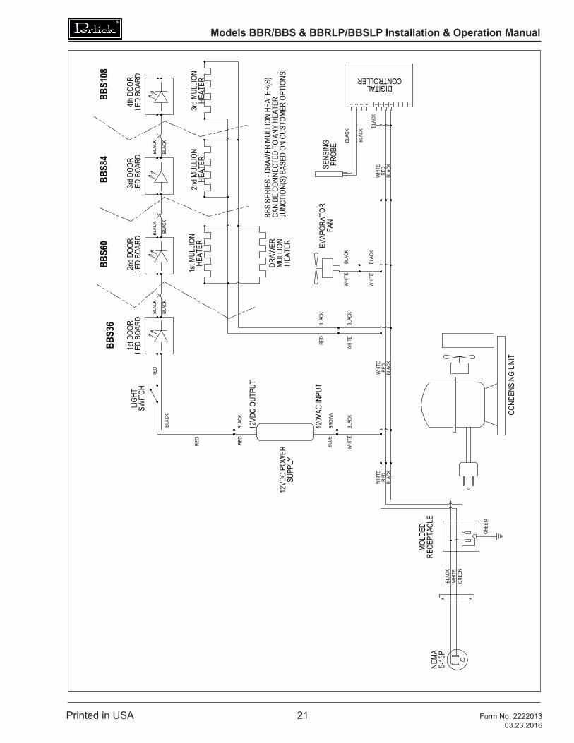
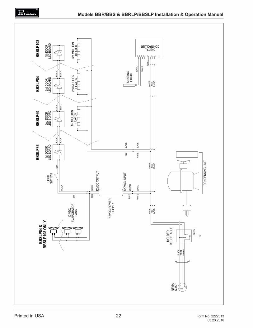
WIRING DIAGRAMS
NOTE
:FI
ELD
WIR
ING
FRO
M C
ABI
NET
JUN
CTI
ON
BO
X TO
CO
ND
ENSI
NG
UN
IT M
UST
CO
MPL
Y W
ITH
ALL
LO
CAL
AN
D N
ATIO
NA
L EL
ECTR
ICA
L CO
DES
Models BBR/BBS & BBRLP/BBSLP Installation & Operation Manual
Printed in USA 20 Form No. 222201303.23.2016
Models BBR/BBS & BBRLP/BBSLP Installation & Operation Manual
Printed in USA 21 Form No. 222201303.23.2016
Models BBR/BBS & BBRLP/BBSLP Installation & Operation Manual
Printed in USA 22 Form No. 222201303.23.2016
98764321
1st M
ULLIO
NHE
ATER
LED
BOAR
D1s
t DOO
RLE
D BO
ARD
2nd D
OOR
LED
BOAR
D3r
d DOO
RLE
D BO
ARD
4th D
OOR
NEMA
5-15
P
HEAT
ER2n
d MUL
LION
HEAT
ER
BBSL
P36
BBSL
P60
BBSL
P84
BBSL
P108
3rd M
ULLIO
N
12VD
C PO
WER
FANS
EVAP
ORAT
OR
PROB
E
COND
ENSI
NG U
NIT
SENS
ING
SWIT
CHLIG
HT
CONTROLLER
BLAC
K
BLAC
KW
HITE
RED
DIGITAL
RECE
PTAC
LE
BLAC
KRE
DW
HITE
BLAC
KW
HITE
GREE
N
RED
BLAC
K
BLAC
KRE
D
MOLD
ED
SUPP
LY
GREE
N
RED
WHI
TEBL
ACK
WHI
TEBL
ACK
RED
BLAC
K
BLUE
BROW
N
BLAC
K
BLAC
K
BLAC
K
BLAC
KBL
ACK
BLAC
K BLAC
K
BLAC
K
12VD
C OU
TPUT
120V
AC IN
PUT
RED
WHI
TE
BLAC
K
12 V
DC
BBSL
P84 &
BB
SLP1
08 O
NLY
JMP
2
2
B A
3
C
B A
1
C
13
SW
ANGU
LAR:
, FR
ACTI
ONS:
INCL
UDIN
G P
HOTO
COPY
ING,
REC
ORDI
NG, O
R US
ED IN
ANY
INFO
RMAT
ION
STOR
AGE,
TRA
NSMI
SSIO
N, O
R RE
TRIE
VAL S
YSTE
M, W
ITHO
UT W
RITT
EN P
ERMI
SSIO
N FR
OM T
HE P
ERLIC
K CO
RPOR
ATIO
N. C
OPYR
IGHT
2001
PER
LICK
CORP
ORAT
ION.
ALL
RIG
HTS
RESE
RVED
.
SHEE
T 1 O
F 1
SCAL
E =
TITL
E:
Per
lick
Cor
pora
tion
MATE
RIAL
:
DATE
SIGN
ATUR
ESDE
SIGN
ED
DRAW
N
CHEC
KED
Milw
auke
e, W
isco
nsin
PURC
HASE
REC
.:
REFE
RENC
E:
THIS
DOC
UMEN
T / P
UBLIC
ATIO
N / S
OFTW
ARE
/ DRA
WIN
G C
ONTA
INS
PROP
RIET
ARY
INFO
RMAT
ION
WHI
CH IS
THE
PRO
PERT
Y OF
THE
PER
LICK
CORP
ORAT
ION.
IT M
AY N
OT B
E RE
PROD
UCED
OR
TRAN
SMIT
TED
IN A
NY F
ORM,
ELE
CTRO
NIC
OR M
ECHA
NICA
L,
PART
NO.
DWG
NO.
REVI
SION
S
WIR
ING
DIA
GRA
MBB
SLP
SERI
ES C
ABIN
ETS
9532
1
JMP
2/26/2
016
1:1
QTY.
:
FINIS
H:
A2/2
6/201
6RE
LEAS
E FO
R PR
ODUC
TION
UNLE
SS O
THER
WIS
E SP
ECIF
IED:
RADI
US S
HARP
FILL
ETS
- .01
5 TO
.031
BREA
K SH
ARP
EDGE
S - 0
15 X
45°.
DIME
NSIO
NS A
RE IN
INCH
ESTO
LERA
NCES
:
.X= ,
.XX
= ,.X
XX =
,
J:\Dw
g\950
00\95
321.s
lddrw

Models BBR/BBS & BBRLP/BBSLP Installation & Operation Manual
Printed in USA 23 Form No. 222201303.23.2016
BLAC
K
UNIT
MUS
T CO
MPLY
WIT
H AL
L LOC
ALJU
NCTI
ON B
OX T
O CO
NDEN
SING
LED
BOAR
D3r
d DOO
RLE
D BO
ARD
4th D
OOR
2nd M
ULLIO
NHE
ATER
2nd D
OOR
LED
BOAR
D
TYPI
CAL
FIEL
D IN
STAL
LATI
ON
WHITE
HEAT
ER3r
d MUL
LION
FAN
EVAP
ORAT
OR
SWIT
CHRE
D
BLAC
K
LIGHT
SUPP
LYRE
D
BLAC
K
BLUE
BROW
NBL
ACK
WHITE
BLAC
KBL
ACK
BLAC
K
BLAC
K12
VDC
POW
EROU
TPUT
12VD
CIN
PUT
120V
ACLE
D BO
ARD
RED
BLACK
WHITE
BLAC
K
WHI
TE
BLAC
K
WHI
TEW
HITE
BLAC
K
1st D
OOR
FAN
EVAP
ORAT
OR
JUNC
TION
BOX
WHI
TEBL
ACK
RED
BLACK
RED
CABI
NET
THES
E W
IRES
CAP
PED
INST
ALLA
TION
S
BLACK
SWIT
CH
GREE
N
BLAC
KW
HITE
GREEN
IN S
INGL
E CA
BINE
TCONN
ECTI
ONPO
WER
PRES
SURE
COND
ENSI
NG U
NIT
1st M
ULLIO
NHE
ATER
BLACK
AND
NATI
ONAL
ELE
CTRI
CAL C
ODES
NOTE
:FI
ELD
WIR
ING
FROM
CAB
INET
BBRL
P48
BBRL
P72
BBRL
P96
JMP
2
2
B A
3
C
B A
1
C
13
SW
BREA
K SH
ARP
EDGE
S - 0
15 X
45°.
2/26/2
016
SHEE
T 1 O
F 1
SCAL
E =
TITL
E:
Per
lick
Cor
pora
tion
MATE
RIAL
:
DATE
SIGN
ATUR
ESDE
SIGN
ED
DRAW
N
CHEC
KED
Milw
auke
e, W
isco
nsin
PURC
HASE
REC
.:
REFE
RENC
E:
THIS
DOC
UMEN
T / P
UBLIC
ATIO
N / S
OFTW
ARE
/ DRA
WIN
G C
ONTA
INS
PROP
RIET
ARY
INFO
RMAT
ION
WHI
CH IS
THE
PRO
PERT
Y OF
THE
PER
LICK
CORP
ORAT
ION.
IT M
AY N
OT B
E RE
PROD
UCED
OR
TRAN
SMIT
TED
IN A
NY F
ORM,
ELE
CTRO
NIC
OR M
ECHA
NICA
L,
PART
NO.
DWG
NO.
REVI
SION
S
WIR
ING
DIA
GRA
M -
BBR
LP48
,BB
R72L
P, &
BBR
LP96
CAB
INET
S
9532
2
JMP
RADI
US S
HARP
FILL
ETS
- .01
5 TO
.031
1:1
QTY.
:
FINIS
H:
A2/2
6/201
6RE
LEAS
E FO
R PR
ODUC
TION
UNLE
SS O
THER
WIS
E SP
ECIF
IED:
INCL
UDIN
G P
HOTO
COPY
ING,
REC
ORDI
NG, O
R US
ED IN
ANY
INFO
RMAT
ION
STOR
AGE,
TRA
NSMI
SSIO
N, O
R RE
TRIE
VAL S
YSTE
M, W
ITHO
UT W
RITT
EN P
ERMI
SSIO
N FR
OM T
HE P
ERLIC
K CO
RPOR
ATIO
N. C
OPYR
IGHT
2001
PER
LICK
CORP
ORAT
ION.
ALL
RIG
HTS
RESE
RVED
.
ANGU
LAR:
, FR
ACTI
ONS:
DIME
NSIO
NS A
RE IN
INCH
ESTO
LERA
NCES
:
.X= ,
.XX
= ,.X
XX =
,
J:\Dw
g\950
00\95
322.s
lddrw
Models BBR/BBS & BBRLP/BBSLP Installation & Operation Manual
Printed in USA 24 Form No. 222201303.23.2016
WARRANTYThe terms and conditions set forth below together with those appearing on the face of the Acknowledgement (the “Order”) constitute the complete and exclusive agreement between Perlick Corporation and the Buyer pertaining to the goods and/or services identified in the Order. If there is a discrepancy or conflict between any exhibit or supplement to the Order and these terms and conditions, these terms and conditions shall control. The Order is intended by Seller and Buyer to be the complete, exclusive, and final statement of their agreement. Any changes to an Order must be in writing and signed by Perlick and Buyer.
TERMS NET 30 DAYSPayment by Visa, MasterCard, American Express or Discover card accepted or cash in advance unless prior accommodations have been made with our Credit Department. Please direct inquiries for detailed information to our Credit Manager. All sales, excise, or similar taxes required by law to be collected or paid by seller shall be in addition to prices quoted unless an appropriate Tax Exemption certificate is furnished. All goods are sold F.O.B. factory. Except for otherwise provided, Perlick will not be responsible for freight, transportation, insurance, shipping, storage, handling, demurrage or similar charges. Invoices are payable in full in thirty (30) days following the invoice‚s date of issuance. If by the terms of sale credit is extended, Perlick reserves the right to revoke such credit if buyer fails to pay for any products when due and may demand payment prior to the commencement of any further shipment.
WAIVERAny waiver of strict compliance with the provisions of an Order must be in writing. No such waiver shall be construed as a waiver of any other term or condition except as provided in writing, nor as a waiver of any subsequent breach of the same term or condition.
METHOD OF SHIPMENTAll shipments are carefully packed and labeled. Crates, boxes and cartons used are of approved weight and strength. Freight rates are based upon 100 pound minimum.
LOST and DAMAGED MERCHANDISETHE RESPONSIBILITY OF THE PERLICK CORPORATION CEASES UPON ACCEPTANCE OF ITS PRODUCTS BY THE CARRIER. Any damage or loss sustained in shipment is the carrier’s responsibility. Before giving the carrier a clean receipt at time of delivery, make sure you receive every item on the bill and inspect every carton, crate and box for concealed damage, i.e., broken boards, crushed or punctured cartons, torn cardboard. IF ANY ITEMS ARE SHORT OR DAMAGED, DO NOT ACCEPT THE SHIPMENT UNLESS THE CARRIER MAKES A NOTATION OF THIS ON YOUR FREIGHT BILL. Then request an inspection. Do not destroy the packing materials. If their agent does not make an inspection within five days, advise the carrier via letter that you notified them regarding the matter and they have failed to act. You will need this letter to support your claim. Then file a claim for your loss. When you give the carrier a clean receipt, you accept the total responsibility for the shipment. UPS shipments are insured individually and UPS will replace all merchandise that is lost or damaged.
RETURN OF MERCHANDISEDo not return any merchandise without our approval. Merchandise returned without a return merchandise authorization number will not be accepted at Perlick. Used, discontinued, and certain custom made items cannot be returned for credit. These custom items include non-catalog products (specials) as well as custom assembled catalog products. Catalog items are designated as non-returnable on the price list page on which they appear. Items returned must be in new condition and packaged in their original carton or crate. Freight charges must be prepaid on all return shipments.
Models BBR/BBS & BBRLP/BBSLP Installation & Operation Manual
Printed in USA 25 Form No. 222201303.23.2016
When a return is authorized, a credit may be allowed pending an examination of the returned goods. The amount of the restocking charge will depend on the condition of the equipment. The minimum restocking charge for glass washers, bottle coolers, frosters, direct draws, cooler series back bars and accessory parts is 20%. The minimum restocking charge for custom series cabinets is 50%. The minimum restocking charge for un-assembled, freestanding underbar stainless steel modules is 20%. Assembled under bar modules are considered custom products and are not returnable for credit. The restocking charge on the item returned is either a percentage of the value of the item or $35.00, whichever is greater.
ONE YEAR PARTS WARRANTYPerlick products are guaranteed against defects in both material and workmanship for a period of one year from date of sale. Defective parts will be replaced on a no-charge basis, F.O.B. our factory, when adjudged defective upon inspection. We are not responsible for parts damaged by alteration, unauthorized service, accident or abuse. All costs associated with replacement, including freight, labor and/or loss of sales, are the responsibility of the user..
ONE YEAR LABOR WARRANTYIn addition to Perlick’s one year parts warranty and five year compressor warranty, ALL PERLICK REFRIGERATION SYSTEMS are offered with a one year labor warranty at no extra charge. Perlick’s one year labor warranty provides that Perlick will pay for the cost of any labor to replace any defective part for up to one year after installation, subject to the following terms and conditions:
(A) Parts returned to Perlick shall be returned freight prepaid and shall be identified with Perlick’s serial number and return authorization number.
(B) Improper operation due to voltage variances, inadequate wiring and physical damage is the responsibility of the purchaser. They are not manufacturing defects.
(C) Condenser coils shall be cleaned regularly. Failure to provide an adequate flow of cooling air will void this warranty.
(D) Factory-specified maintenance and installation will be provided by the selling dealer who shall also be responsible for the installation and set-up of these products in accordance with local plumbing, refrigeration and electrical codes.
Perlick’s one year labor policy applies to the United States and Canada. IT DOES NOT APPLY TO REFRIGERATION SYSTEMS ADDED BY OTHERS (remote systems) or any part which has been subject to misuse, neglect, alteration, accident, or to any damage caused by transportation, flood, fire or other acts of God.

Models BBR/BBS & BBRLP/BBSLP Installation & Operation Manual
Printed in USA 26 Form No. 222201303.23.2016
NOTES
Models BBR/BBS & BBRLP/BBSLP Installation & Operation Manual
Printed in USA 27 Form No. 222201303.23.2016
NOTES

8300 West Good Hope Road • Milwaukee, WI 53223 •
Toll Free 800.558.5592 • Fax 414.353.7069 • www.perlick.com

![Figure 1 Figure 2 BevJet II Parts List Matrix BevJet II · Width 4.06“ [103.1mm] Height 2.67” [67.9 mm] Flow Rate: 1.0 GPM (3.8 LPM) Max Amp draw: 2.5 amp at 25 PSI (1.7 bar)](https://img.pdfslide.us/doc/110x75/601bafc8e6c40d71f6429be8/figure-1-figure-2-bevjet-ii-parts-list-matrix-bevjet-ii-width-406aoe-1031mm.jpg)