Embed Size (px)
Citation preview

1 to 40 oz./min. and 5 to 200 oz./min.[0.3 to 11.8 dL/min. and 1.5 to 59 dL/min.]
Sidekick Pro™
Installation & Operation Manual

While every effort has been made to ensure the accuracy of this document, Raven Industries assumes no responsibility for omissions and errors. Nor is any liability assumed for damages resulting from the use of information contained herein.
Raven Industries shall not be responsible or liable for incidental or consequential damages or a loss of anticipated benefits or profits, work stoppage or loss, or impairment of data arising out of the use, or inability to use, this system or any of its components. Raven Industries shall not be held responsible for any modifications or repairs made outside our facilities, nor damages resulting from inadequate maintenance of this system.
As with all wireless and satellite signals, several factors may affect the availability and accuracy of wireless and satellite navigation and correction services (e.g. GPS, GNSS, SBAS, etc.). Therefore, Raven Industries cannot guarantee the accuracy, integrity, continuity, or availability of these services and cannot guarantee the ability to use Raven systems, or products used as components of systems, which rely upon the reception of these signals or availability of these services. Raven Industries accepts no responsibility for the use of any of these signals or services for other than the stated purpose.
Disclaimer
©Raven Industries, Inc. 2010, 2012

Table of Contents
Chapter 1 Important Safety Information................................................. 1
Chemical Handling and Safety ............................................................................................ 1Electrical Safety ................................................................................................................... 2
Chapter 2 Introduction............................................................................. 3
System Overview ...................................................................................................................... 3Injection System Components ............................................................................................. 3
Sidekick Pro Features ............................................................................................................... 4Closed Calibration System .................................................................................................. 4Integrated Motor Control Node ............................................................................................ 5Fast Rate Response ............................................................................................................ 5System Diagnostics ............................................................................................................. 6
Sidekick Pro Pump Specifications ............................................................................................. 6Updates ..................................................................................................................................... 9
Chapter 3 Installation............................................................................. 11
Overview ................................................................................................................................. 11Initial Plumbing and Point of Injection ..................................................................................... 12Mount the Sidekick Pro Pump and Chemical Tank ................................................................. 15
Mount the Injection Module ............................................................................................... 15Mount the Chemical Tank .................................................................................................. 16Mount the Sidekick Pro Pump ........................................................................................... 16
Sidekick Pro Injection System Plumbing ................................................................................. 18Plumb the Sidekick Pro Pump ........................................................................................... 18Plumb the Sidekick Pro Closed Calibration System .......................................................... 19Plumb the Recommended Pump Rinse System ............................................................... 20
CANbus and Power Connections ............................................................................................ 22Generation 1 Cabling Platform .......................................................................................... 22Generation 2 Cabling Platform .......................................................................................... 24Sidekick Pro CANbus Connection ..................................................................................... 28
Detecting and Addressing the Motor Control Node ................................................................. 29Alternate Method to Readdress the Injection Motor Control Node .................................... 29
Verifying Installation of the Sidekick Pro ................................................................................. 29
Manual No. 016-0171-391 i

Table of Contents
Chapter 4 Calibration and Operation ................................................... 31
Control Console Calibration ....................................................................................................31Pump Type ........................................................................................................................ 31Meter Cal ........................................................................................................................... 33Valve Type and Valve Cal ..................................................................................................33Rate Cal ............................................................................................................................. 33Flow Cal (Envizio Pro only) ...............................................................................................34FER Cal (SCS 4000/5000 Series and Viper Pro only) ...................................................... 34Pressure Transducer Calibration .......................................................................................34
Control Features and Application Modes ................................................................................35Application Modes .............................................................................................................36Flow Monitor Features .......................................................................................................37Agitator .............................................................................................................................. 37
Sidekick Pro Priming and Calibration ......................................................................................37Verify Control Console Settings .........................................................................................38Prime the Injection Pump ..................................................................................................38Calibrate the Injection Pump .............................................................................................39
Chapter 5 Setting Application Mode and Injection Diagnostics........ 43
Viper Pro ................................................................................................................................. 43Application Mode Setup .....................................................................................................43Injection Diagnostics Display ............................................................................................. 44
Envizio Pro .............................................................................................................................. 45Application Mode Setup .....................................................................................................45Enabling Alarms ................................................................................................................46Injection Diagnostics Display ............................................................................................. 47
SCS 4000/5000 Series ............................................................................................................ 48Application Mode Setup .....................................................................................................48Injection Diagnostics Display ............................................................................................. 49
Chapter 6 System Maintenance ............................................................ 51
Maintenance and Cleaning ......................................................................................................51Check Valve O-Rings ........................................................................................................52Pump Cam and Bearing ....................................................................................................54Piston Seal Replacement ..................................................................................................54
Seasonal Maintenance and Storage .......................................................................................57
ii Sidekick Pro™ Installation & Operation Manual

Table of Contents
Chapter 7 Troubleshooting ................................................................... 59
Motor Control Node LED Status Indicators ............................................................................. 59Alarms ..................................................................................................................................... 60
Chapter 8 Replacement Parts ............................................................... 63
Sidekick Pro Pump Replacement Parts .................................................................................. 63Injection Pump Pressure Transducer ................................................................................ 64Injection Pump Vacuum Switch ......................................................................................... 65Injection Pump Flow Monitor Sensor ................................................................................. 65Injection Pump Encoder .................................................................................................... 67Check Valve Assemblies ................................................................................................... 69Sidekick Pro™ 1 to 40 oz./min. Pump ............................................................................... 70Sidekick Pro™ 5 to 200 oz./min. Pump ............................................................................. 73
Sidekick Pro Module Replacement Parts ................................................................................ 76Modules with 24 Gallon Tank and 1 to 40 oz./min. Pump ................................................. 76Modules with 24 Gallon Tank and 5 to 200 oz./min. Pump ............................................... 80
Chapter 9 System Diagrams.................................................................. 85
Manual No. 016-0171-391 iii

Table of Contents
iv Sidekick Pro™ Installation & Operation Manual

CHAPTER
1
Manual No. 016-0171-391 Rev. B
Chapter 1Important Safety Information
Read this manual carefully before installing the Raven Sidekick Pro, injection module or any other system components.
• Follow all safety information presented within this manual.
• Keep safety labels in good condition. Replace missing or damaged safety labels as necessary and verify labels are included on replacement parts or new equipment components. Replacement safety labels are available from any local Raven dealer.
• If you require assistance with any portion of the installation or service of Raven equipment, contact a local Raven dealer for support.
When operating the machine after installing the Raven Sidekick Pro, observe the following safety measures:
• Be alert and aware of surroundings.
• Do not operate any agricultural equipment while under the influence of alcohol or an illegal substance.
• Determine and remain a safe working distance from obstacles or other individuals. The equipment operator is responsible for disabling the system when a safe working distance has diminished.
Review the operation and safety instructions included with the implement and/or controller.
Chemical Handling and Safety
Chemicals used in agricultural applications may be harmful to your health or the environment if not used responsibly. Review the safe, effective, and legal use and disposal of agricultural chemicals with a chemical supplier.
• Always follow safety labels and instructions provided by the chemical manufacturer or supplier.
NOTICE
WARNING
1

Chapter 1
• Store agricultural chemicals in original containers and do not transfer to unmarked containers or containers used for food or drink. Store chemicals in a secure, locked area away from human or livestock food and keep children away from storage areas.
• Avoid inhaling chemical dust or spray particulate and avoid direct contact with agricultural chemicals. Always wear appropriate personal protective equipment as recommended by the chemical and/or equipment manufacturer. Wash hands and face after using agricultural chemicals and before eating, drinking, or using the rest room.
• Seek medical attention immediately if illness occurs during or shortly after the use of chemicals.
• Fill, flush, calibrate, and decontaminate sprayer systems in an area where runoff will not reach ponds, lakes/streams, livestock areas, gardens, or populated areas. Thoroughly flush or rinse equipment used to mix, transfer, and apply chemicals after use.
• Before servicing any component of the system, thoroughly flush or rinse components with water.
• Improper disposal of waste may threaten the environment and ecology. Dispose of empty containers properly. Triple-rinse empty containers and puncture or crush when disposing. Contact a local environmental or recycling center for additional information.
If the system malfunctions or becomes clogged, stop the engine or pump and relieve pressure from the spraying system before servicing.
Do not operate machinery without instruction and keep equipment in proper working condition. Unauthorized modification to equipment may impair machine function and/or safety and may shorten the working life of equipment.
Wear clothing appropriate for the job being performed and avoid loose fitting clothing while working on or near moving components. Keep long hair away from moving components.
Electrical Safety
Do not reverse power leads. Doing so could cause severe damage to the equipment. Always make sure that the power leads are connected to the correct polarity as marked. Ensure that the power cables are the last cables to be connected.
Remove rings and other jewelry to prevent electrical shorts or entanglement in moving parts.
CAUTION
2 Sidekick Pro™ Installation & Operation Manual

CHAPTER
2
Manual No. 016-0171-391 Rev. B
Chapter 2Introduction
System OverviewThe Raven Sidekick Pro injection system is designed to provide efficient and accurate application of liquid chemicals applied from an injection module. Using a separate injection module, or tank, eliminates mixing chemicals and reduces chemical waste, and simplifies equipment care and maintenance.
Sidekick Pro provides connectivity to a Raven CANbus system to allow an existing Raven CAN control console to control the rate of the chemical injection system.
After proper installation and calibration of the injection system and Raven controller, including a set target rate for the carrier and injected chemicals, the operator enables the product control system and the control console will automatically maintain the flow regardless of vehicle speed or active boom sections.
Performance of the Raven injection system relies upon proper installation and maintenance of the complete sprayer system. Please review this manual before installing or operating this system to help ensure proper setup and follow instructions provided for proper care and maintenance of the Raven injection system.
Injection System Components
The Raven injection system consists of:
• Raven CAN based control console and appropriate cabling
• Sidekick Pro injection pump
• In-line mixer
• Cabling required to connect injection system components and existing CANbus
• Check valves
The following Raven CAN control consoles may be used with the injection system
• SCS 4000/5000 Series
• Envizio Pro or Envizio Pro II
• Viper Pro
3
Chapter 2
Sidekick Pro Features
Closed Calibration System
Calibrating chemical injection pumps is necessary for accurate chemical injection applications. The Sidekick Pro closed calibration system allows the operator to perform calibration or system tests without catching or handling dangerous chemicals.
Priming
An automatic priming feature ensures the pump is correctly primed and ready for operation when the operator is ready to apply product.
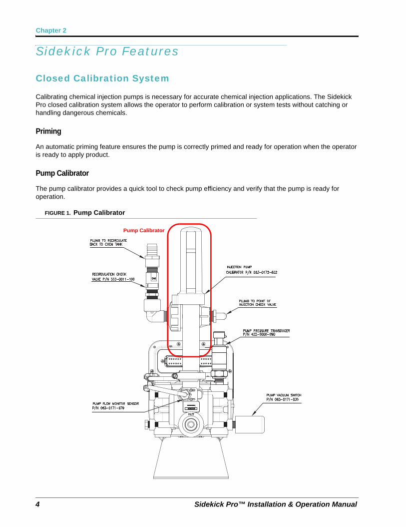
Pump Calibrator
The pump calibrator provides a quick tool to check pump efficiency and verify that the pump is ready for operation.
FIGURE 1. Pump Calibrator
Pump Calibrator
4 Sidekick Pro™ Installation & Operation Manual

2
Introduction
Integrated Motor Control Node
Sidekick Pro features an integrated motor control node mounted directly on the pump housing for simplified installation and enhanced performance. The control node features status LEDs which provide status and CAN communication information which the operator may be able to use during calibration or system troubleshooting.
Integrated Calibration Switch
The integrated motor control node also features a sealed calibration switch. The sealed calibration switch allows the operator to begin the pump calibration process by passing a metallic object, such as a screwdriver, across the switch sensor on the Sidekick Pro injection pump. This feature allows the operator to run multiple calibration tests quickly and easily and ensure the system is ready for operation.
Note: Calibration may also be initiated from the control console in the vehicle cab. See the Calibrate the Injection Pump section on page 39 for a detailed calibration procedure.
The calibration status LED light will flash when the calibration sensor registers a metallic object by the switch. Pass the metal object past the sensor twice to initiate a pump calibration.
FIGURE 2. Motor Control Node Calibration Sensor
Fast Rate Response
The Sidekick Pro direct injection system is capable of making accurate adjustments to chemical injection rates more quickly than previous Raven injection systems to help ensure accurate and proper chemical applications in the field.
Calibration Sensor Location
Calibration Status LED
Manual No. 016-0171-391 Rev. B 5
Chapter 2
System Diagnostics
Enhanced diagnostic features are monitored by the control console during operation of the Sidekick Pro injection system to help identify potential issues and minimize equipment down time. Refer to Chapter 5, Setting Application Mode and Injection Diagnostics for more information on using diagnostics features on a specific console.
Flow Monitoring
The CAN integrated Sidekick Pro offers enhanced monitoring of pump operation during chemical injection applications to alert the operator to conditions such as an empty chemical supply tank, low injection pressure, incorrect meter calibration, or issues with the injection pump valves.
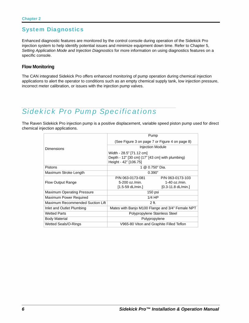
Sidekick Pro Pump SpecificationsThe Raven Sidekick Pro injection pump is a positive displacement, variable speed piston pump used for direct chemical injection applications.
Dimensions
Pump
(See Figure 3 on page 7 or Figure 4 on page 8)
Injection Module
Width - 28.5” [71.12 cm]Depth - 12” [30 cm] (17” [43 cm] with plumbing)Height - 42” [106.75]
Pistons 1 @ 0.750” Dia.
Maximum Stroke Length 0.390”
Flow Output RangeP/N 063-0173-081
5-200 oz./min.[1.5-59 dL/min.]
P/N 063-0173-1031-40 oz./min.
[0.3-11.8 dL/min.]
Maximum Operating Pressure 150 psi
Maximum Power Required 1/4 HP
Maximum Recommended Suction Lift 2 ft.
Inlet and Outlet Plumbing Mates with Banjo M100 Flange and 3/4” Female NPT
Wetted Parts Polypropylene Stainless Steel
Body Material Polypropylene
Wetted Seals/O-Rings V965-80 Viton and Graphite Filled Teflon
6 Sidekick Pro™ Installation & Operation Manual

2
Introduction
FIGURE 3. Sidekick Pro Injection Pump Dimensions (in inches)
Note: 5-200 oz./min. pump shown. Basic dimensions are the same for 1-40 oz./min. pump.
Manual No. 016-0171-391 Rev. B 7

Chapter 2
FIGURE 4. Sidekick Pro Injection Pump Dimensions (Cont.)
Note: 5-200 oz./min. pump shown. Overall length of 1-40 oz./min. pump is 13.25 inches [33.66 cm].
8 Sidekick Pro™ Installation & Operation Manual

2
Introduction
UpdatesUpdates for Raven manuals as well as several system components are available at the Applied Technology Division web site:
www.ravenhelp.com
Sign up for e-mail alerts to receive notice when updates for your Raven products are available on the Raven web site.
At Raven Industries, we strive to make your experience with our products as rewarding aspossible. One way to improve this experience is to provide us with feedback on this manual.
Your feedback will help shape the future of our product documentation and the overall servicewe provide. We appreciate the opportunity to see ourselves as our customers see us and areeager to gather ideas on how we have been helping or how we can do better.
To serve you best, please send an email with the following information to
-Sidekick Pro™ Installation & Operation Manual-Manual No. 016-0171-391 Rev. B-Any comments or feedback (include chapter or page numbers if applicable).-Let us know how long have you been using this or other Raven products.
We will not share your email or any information you provide with anyone else. Your feedbackis valued and extremely important to us.
Thank you for your time.
Manual No. 016-0171-391 Rev. B 9

Chapter 2
10 Sidekick Pro™ Installation & Operation Manual

CHAPTER
3
Manual No. 016-0171-391 Rev. B
Chapter 3Installation
OverviewThe following steps must be completed to install a Raven Sidekick Pro injection system:
1. Select and plumb the point of injection. See page 12.
a. Install carrier and chemical injection check valves.
b. Install in-line mixer.
2. Mount the Sidekick Pro injection module or tank. See page 15.
3. Mount the Sidekick Pro injection pump. See page 16.
4. Plumb the Sidekick Pro pump and injection lines into the main carrier line at point of injection. See page 18.
5. Install the closed calibration system. See page 19.
6. Plumb the recommended rinse system. See page 20.
7. Connect the Sidekick Pro injection pump to CANbus. See page 22.
8. Connect the Sidekick Pro pump to source of electrical power. See page 22.
The following sections provide detailed information and procedure to assist with completing the above steps. Contact a local Raven dealer for assistance or questions during the installation procedure.
FIGURE 1. Example Sidekick Pro Injection System
11
Chapter 3
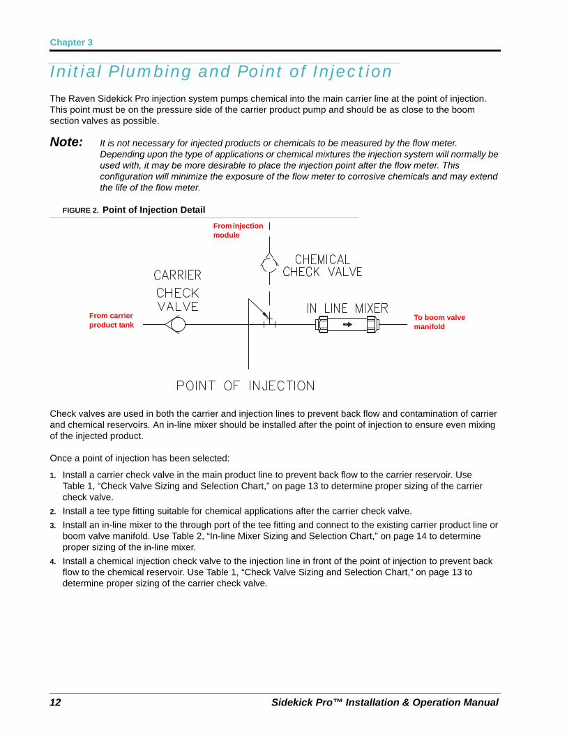
Initial Plumbing and Point of InjectionThe Raven Sidekick Pro injection system pumps chemical into the main carrier line at the point of injection. This point must be on the pressure side of the carrier product pump and should be as close to the boom section valves as possible.
Note: It is not necessary for injected products or chemicals to be measured by the flow meter. Depending upon the type of applications or chemical mixtures the injection system will normally be used with, it may be more desirable to place the injection point after the flow meter. This configuration will minimize the exposure of the flow meter to corrosive chemicals and may extend the life of the flow meter.
FIGURE 2. Point of Injection Detail
Check valves are used in both the carrier and injection lines to prevent back flow and contamination of carrier and chemical reservoirs. An in-line mixer should be installed after the point of injection to ensure even mixing of the injected product.
Once a point of injection has been selected:
1. Install a carrier check valve in the main product line to prevent back flow to the carrier reservoir. Use Table 1, “Check Valve Sizing and Selection Chart,” on page 13 to determine proper sizing of the carrier check valve.
2. Install a tee type fitting suitable for chemical applications after the carrier check valve.
3. Install an in-line mixer to the through port of the tee fitting and connect to the existing carrier product line or boom valve manifold. Use Table 2, “In-line Mixer Sizing and Selection Chart,” on page 14 to determine proper sizing of the in-line mixer.
4. Install a chemical injection check valve to the injection line in front of the point of injection to prevent back flow to the chemical reservoir. Use Table 1, “Check Valve Sizing and Selection Chart,” on page 13 to determine proper sizing of the carrier check valve.
From carrier product tank
To boom valve manifold
From injection module
12 Sidekick Pro™ Installation & Operation Manual

3
Installation
FIGURE 3. Check Valve Thread
Note: Be sure to install the check valves with the flow direction indicator pointing in the direction of chemical flow.
TABLE 1. Check Valve Sizing and Selection Chart
Raven Part No. “A” NPT “B” NPT
Recirculation and Priming Check
Valvea
a. Has 0.046” Bleed Hole.
333-0011-100 1/2” (F) 1/2” (M)
Injection Point Check valve 12 PSI [82.74 kPa]
333-0011-102 1/2” (F) 1/2” (M)
Carrier Check Valve
333-0011-090 1” 1”
333-0011-091 1-1/4” 1-1/4”
333-0011-093 2” 2”
333-0011-094 3” 3”
333-0011-095 4” 4”
Port APort B Port A
Port B
Carrier Check Valve Injection Point Check Valve
Port APort B
Recirculation/Priming Check Valve
Stainless Steal Mixer Assembly
Port A
Port B
Manual No. 016-0171-391 Rev. B 13

Chapter 3
TABLE 2. In-line Mixer Sizing and Selection Chart
FIGURE 4. Pressure Drop vs. Flow Rate
Raven Part No. “A” NPT “B” NPT
Polypropylene
063-0171-303 1” 1”
063-0159-632 1-1/4” 1-1/4”
063-0171-300 2” 2”
Stainless Steel 333-9000-010 3” 3”
Cast Iron 063-0171-784 1” 1”
Stainless Steel Mixer
Assemblya
a. 3” Check Valve and 3” Banjo Flange included in assembly.
063-0173-264 4” 4”
2” Check Valve and 2” Mixer
3” Check Valve and 3” Mixer
3” Check Valve and 4” Mixer
Flow RateGal./min. [L/min.]
Pressure Drop (PSI [kPa]
14 Sidekick Pro™ Installation & Operation Manual

3
Installation
Mount the Sidekick Pro Pump and Chemical TankInstallation and mounting of the Sidekick Pro injection pump and injection module, or chemical tank, will vary between implements. Use the following sections to help select an appropriate mounting location on the implement.
Mount the Injection Module
The Raven Sidekick Pro injection module provides a platform for mounting the chemical supply tank and Sidekick Pro injection pump in the optimal configuration for pump operation.
FIGURE 5. Injection Module Platform Dimensions
Note: The Raven Sidekick Pro injection module may be ordered with a 24 gallon chemical supply tank or without a chemical tank to connect the injection system with an existing tank on the vehicle or purchased separately.
The assembled injection module will measure approximately as follows:Width - 28.5” [71.12 cm]Depth - 12” [30 cm] (17” [43 cm] with plumbing)Height - 42” [106.75]
• Mount the injection module platform in an area close to the boom valve manifold. This minimizes the volume of chemical in the injection line between the pump and point of injection and allows for more accurate control of the injected chemical.
• Verify that the hand valves and drain are accessible in the selected mounting location.
• Verify that the injection pump is accessible to perform periodic maintenance.
42”[106.75 cm]
28.5”[71.12 cm]
Manual No. 016-0171-391 Rev. B 15
Chapter 3
Mount the Chemical Tank
Note: If a Raven injection module is used, the supplied platform provides an ideal mounting configuration for the Sidekick Pro injection pump and chemical tank.
• Mount the chemical tank or injection module as close as possible to the injection pump. Minimize the length of the product line between the chemical tank and injection pump. Avoid any product lines longer than 5 ft. [1.5 m] between the chemical tank and injection pump inlet port.
Note: Long product lines between the chemical tank and injection pump may cause high vacuum pressures on the pump inlet, long pump priming times or difficulty priming the pump, and larger amounts of chemical waist during rinsing.
If vacuum errors are encountered during pump operation, one or both of the following corrective measures may be necessary to reduce inlet pressure:
• Reduce the inlet plumbing length
• Increase the tubing size
• Mount the Sidekick Pro pump so that the line between the injection pump and chemical supply tank is near level with a slight incline to help relieve air bubbles. The line connected to the pump inlet must not raise chemical above 2 ft. [0.6 m] from the chemical supply tank outlet. See Figure 8 on page 21.
Mount the Sidekick Pro Pump• Mount the Sidekick Pro pump as close as possible to the selected point of injection.
• Mount the Sidekick Pro pump so that the outlet port is pointing up. The pump will not meter product application correctly if the pump is mounted in any other orientation.
• The Sidekick Pro should be mounted in a location which provides access to the pump and control node to simplify calibration and troubleshooting.
16 Sidekick Pro™ Installation & Operation Manual

3
Installation
FIGURE 6. Sidekick Pro Pump Mounting and Bracket Orientation
Note: The pump mounting bracket may be rotated to accommodate mounting to a vertical surface, however, the injection pump must be mounted level with the outlet port perpendicular to the ground.
Pump Outlet
Pump Inlet
Pump Mounting Bracket
Manual No. 016-0171-391 Rev. B 17

Chapter 3
FIGURE 7. Sidekick Pro Pump Mounting Bracket Bolt Pattern
Sidekick Pro Injection System Plumbing
Plumb the Sidekick Pro Pump
Pump Inlet
Use 3/4” chemically resistant hose between the chemical tank and injection pump inlet. Do not use hose or tubing that may collapse when a vacuum is applied during pump operation.
The product line should be as straight as possible. Avoid low spots in plumbing to ease pump priming and avoid chemical waist.
Strainer
A strainer with a #20 mesh screen must be installed on the inlet side of the injection pump.
18 Sidekick Pro™ Installation & Operation Manual

3
Installation
Pump Outlet
Connect the pump outlet to the injection check valve at the point of injection. Use the following hose sizes depending upon the capacity of the injection pump used with the system.
Avoid product lines longer than 15 ft. [4.5 m] between the pump outlet and the point of injection. Long runs can cause increased pressure in the pump heads which cause the pump to pull more electrical current and may raise the temperature of the injection pump motor and integrated motor control node. See the Setting Application Mode and Injection Diagnostics section on page 43 for details on injection system diagnostics and to monitor pump pressure and node temperature.
Plumb the Sidekick Pro Closed Calibration System
The Sidekick Pro closed calibration system provides an environmentally effective method of calibrating the injection pump without exposing the operator to dangerous or hazardous chemicals.
Pump Calibrator
To provide accurate calibration of the injection pump, the pump calibrator (P/N 063-0172-822) must be installed directly onto the outlet of the pump. This configuration prevents air from getting trapped between the injection pump and the calibration plunger. Trapped air will cause the plunger to feel “spongy” when pressed and will cause the pump calibrator to work improperly.
3-Way Valve
A 3-way valve must be plumbed after the closed calibration system to allow chemical to be directed either back to the chemical tank or to the point of injection.
Hoses
Use chemically resistant hose compatible with the chemicals which will be used with the injection system. Follow the same hose specifications as described in the Pump Outlet section on page 19 with the closed calibration system.
Recirculation Check Valve
A recirculation and priming check valve (P/N 333-0011-100) must be plumbed into the recirculation line between the 3-way valve on the outlet side of the injection pump and the chemical tank. This check valve is required to allow air to bleed off during priming of the injection pump. The recirculation and priming check valve is also necessary to allow the system to detect if the pump is primed. See Figure 1 on page 11.
Pump Capacity Tubing Size
1-40 oz./min. 3/8”
5-200 oz./min. 1/2”
CAUTIONHoses used on the outlet of the injection pump must be re-enforced, chemically resistant hose rated for at least 150 PSI at 100° F [1034 kPa at 66° C].
Manual No. 016-0171-391 Rev. B 19

Chapter 3
Plumb the Recommended Pump Rinse System
An injection pump rinse system is recommended to enhance the performance of the Sidekick Pro injection pump and provide a clean method for changing between chemicals. The rinse system flushes chemical build up or residues which may collect in the injection pump.
Note: Some components of the recommended rinse system may not be available from Raven. The following components may be purchased separately and plumbed as shown in Figure 8 on page 21.
• Clean water supply tank
• Strainer (80 Mesh)
• 1/2 PSI check valve (P/N 333-0011-087)
• Appropriate hose or tubing
• Miscellaneous fittings
20 Sidekick Pro™ Installation & Operation Manual

3
Installation
FIGURE 8. Recommended Injection System Plumbing with Optional Pump Rinse Tank
Manual No. 016-0171-391 Rev. B 21

Chapter 3
CANbus and Power ConnectionsThe Raven Sidekick Pro connects to a Raven CANbus system via a CAN motor control cable and requires both a clean logic power and a high current power connection.
Note: Refer to the installation manual for the specific CAN control console for detailed information about installing and powering a CAN system.
Generation 1 Cabling Platform
The logic and high current power connections must be routed through a properly sized relay and connected directly to battery. This configuration protects the injection system’s electrical components and prevents the implement battery from discharging if left alone for long periods of time.
Best Installation Practices
The information below illustrates proper methods for wiring a CANbus system. The main points of CAN installation are summarized below.
Note: Following these recommendations will result in the most robust system possible while greatly reducing CAN communication problems.
1. Always use sealed connectors with dielectric grease. Avoid unsealed, crimped connections (i.e. butt connectors).
In addition to using dielectric grease, mount all CAN terminators (P/N 063-0172-369) with the connector pointing down to avoid collecting water and/or chemical. Liquids collecting within the terminator can corrode pins and may cause CAN communication issues.
2. Connect the power directly to a controlled clean power source.
3. Connect the ground directly to the vehicle’s battery.
4. Node logic power should be connected to a clean power bus relay.
5. Use dedicated bus bars to connect the console and all nodes to the same source for both power and ground. See Figure 9 on page 23.
6. Provide relays to switch power on and off to avoid draining the battery. Raven recommends connecting the console to a clean power source (at relay) and using the console ‘orange’ wire to activate the relay. This makes the console the master power switch and allows engine shutdown without turning off the console. See Figure 9 on page 23.
CAN Terminators
Two CAN terminators (P/N 063-0172-369) are required to provide optimal signal integrity through the CANbus. These terminators should be installed at each end of the CANbus. A CAN power adapter tee cable (P/N 115-0171-368) should be placed toward the front of the bus with one end terminated. CAN power, obtained from a switched power source, runs throughout the bus to act as a shield.
22 Sidekick Pro™ Installation & Operation Manual

3
Installation
FIGURE 9. Generation 1 CAN Node Power Wiring Diagram
Manual No. 016-0171-391 Rev. B 23

Chapter 3
FIGURE 10. Generation 1 35’ CAN Motor Control Cable with Agitator Connection (P/N 115-0171-943)
FIGURE 11. Generation 1 CAN Motor Control Cable (P/N 115-0171-944)
FIGURE 12. Generation 1 CAN Extension Cables with Tee and Passive Terminator
CANbus Connection
CAN Passive Terminator063-0172-369
CAN Tee Cables4 in. - 115-0171-3646 ft. - 116-0171-326
12 ft. - 115-0171-36224 ft. - 115-0171-363
24 Sidekick Pro™ Installation & Operation Manual

3
Installation
Generation 2 Cabling Platform
The logic and high current power connections for the first Sidekick Pro injection pump are provided within the chassis cable installed on the vehicle. If additional Sidekick Pro injection pumps will be added, a separate cable will be required to provide power for each additional pump. Refer to Figure 14 on page 26.
Best Installation Practices
The information below illustrates proper methods for wiring a CANbus system. The main points of CAN installation are summarized below.
Note: Following these recommendations will result in the most robust system possible while greatly reducing CAN communication problems.
1. Always use sealed connectors with dielectric grease. Avoid unsealed, crimped connections (i.e. butt connectors).
In addition to using dielectric grease, mount all CAN terminators (P/N 063-0172-369) with the connector pointing down to avoid collecting water and/or chemical. Liquids collecting within the terminator can corrode pins and may cause CAN communication issues.
2. Connect the power directly to a controlled clean power source.
3. Connect the ground directly to the vehicle’s battery.
4. Node logic power should be connected to a clean power bus relay.
5. Use dedicated bus bars to connect the console and all nodes to the same source for both power and ground. See Figure 9 on page 23.
6. Provide relays to switch power on and off to avoid draining the battery. Raven recommends connecting the console to a clean power source (at relay) and using the console ‘orange’ wire to activate the relay. This makes the console the master power switch and allows engine shutdown without turning off the console. See Figure 9 on page 23.
CAN Terminators
Two CAN terminators (P/N 063-0172-369) are required to provide optimal signal integrity through the CANbus. These terminators should be installed at each end of the CANbus. A CAN power adapter tee cable (P/N 115-0171-368) should be placed toward the front of the bus with one end terminated. CAN power, obtained from a switched power source, runs throughout the bus to act as a shield.
Manual No. 016-0171-391 Rev. B 25

Chapter 3
FIGURE 13. Generation 2 CAN Motor Control Cable (P/N 115-0171-952)
FIGURE 14. Generation 2 Cabling for Additional Injection Pumps (D/N 054-5000-001)
Note: For applicators operating more than two high volume injection pumps at the same time, select one power cable and one injection node add on cable for each additional pump:
• Power cable, injection pump add on chassis (P/N 115-0171-953)
• Node Cable, 6’ injection pump add on (P/N 115-0171-954)
• Node Cable, 12’ injection pump add on (P/N 115-0171-955)
• Node Cable, 24’ injection pump add on (P/N 115-0171-956)
• Node Cable, 36’ injection pump add on (P/N 115-0171-957)
To Chassis Connection
Node Connectors
Pressure Connector
Flow Connector
To Vacuum Connector
Fuse (5A)
26 Sidekick Pro™ Installation & Operation Manual

3
Installation
FIGURE 15. Generation 2 CAN System Wiring Diagram (D/N 054-5000-001)
Manual No. 016-0171-391 Rev. B 27

Chapter 3
Sidekick Pro CANbus Connection
Review the following diagrams for assistance with installation and connection of the injection pump to the CANbus system.
Note: The high current power and ground lead wires are larger gauge wire than the logic power and ground leads.
FIGURE 16. CAN Motor Control and Pump Connection (D/N 054-6400-006)
Motor Control
Pump Vacuum Sensor
Pump Pressure Transducer
Pump Flow Monitor Sensor
Plumb to Chemical Tank for Recirculation and
Priming
Plumb to Point of Injection Check Valve
Recirculation Check Valve(P/N 333-0011-100)
(has bleed hole, identifiable by 046 stamped on flat surfaces)
Injection Pump Closed Calibrator
(P/N 063-0172-822)
Pump Flow Monitor Sensor
(P/N 063-0171-979)
Pump Vacuum Sensor (P/N 063-0171-035)
Pump Pressure Transducer (P/N 422-0000-090)
28 Sidekick Pro™ Installation & Operation Manual

3
Installation
Detecting and Addressing the Motor Control NodeReview the CAN setup section of the Raven control console manual for detailed CANbus system information.
Alternate Method to Readdress the Injection Motor Control Node
The Sidekick Pro motor control node may be readdressed using either the process described in the CAN control console manual, or by the following procedure:
1. Begin readdressing nodes as described in the Raven control console manual.
2. When prompted to readdress the product number for the injected product, pass a metal object across the calibration sensor located at the point of the white arrow on the side of the node housing.
FIGURE 17. Motor Control Node Calibration Sensor
3. Complete the procedure to readdress nodes as described in the Raven control console manual.
Calibration Sensor Location
Manual No. 016-0171-391 Rev. B 29

Chapter 3
Verifying Installation of the Sidekick ProNote: Before filling the tank with chemical for the first time, thoroughly vacuum the chemical supply tank
and clean any plastic or metal particles that may be left from the manufacturing or installation process. If these particles get stuck within the injection pump, they may cause a significant reduction in pump accuracy. Turn the hand valve(s) to allow the tank to drain without running through the pump or injection plumbing and thoroughly rinse tank prior to testing or running the injection system for the first time.
Perform the procedures outlined in the Normal Application Mode section on page 36 to verify that the system is installed properly.
Fill the chemical supply tank with clean water when checking the installation. Check for any leaks on all plumbing connections before applying chemicals with the injection system. It is recommended to check the system periodically and replace worn or damaged connections, valves, or hoses.
30 Sidekick Pro™ Installation & Operation Manual

CHAPTER
4
Manual No. 016-0171-391 Rev. B
Chapter 4Calibration and Operation
Control Console CalibrationOnce installation of the injection system has been verified, and the motor control node is recognized by the CAN control console, the Sidekick Pro and console must be calibrated to provide accurate control of the injected product.
Note: The Sidekick Pro motor control node is only capable of operating in a liquid chemical application mode.
Regardless of which control console is used to control the Sidekick Pro, the following settings must be calibrated or programmed to ensure proper control and operation of the pump:
• Pump Type
• Meter Cal
• Valve Type and Valve Cal
• Rate Cal
• Flow Cal or FER Error Cal
• Pressure Transducer Cal
Note: These settings must be programmed for each injection product or pump which will be used to control product during an application. Refer to the specific control console manual for instructions on programming these settings or other calibration information on the console.
Pump Type
The type of pump used for chemical injection must be selected during the initial product calibration for each injection pump connected to the control system. Select either “High, 5-200 oz./min.” [1.5-59 dl/min.] or“Low, 1-40 oz./min.” [0.3-11.8 dl/min.] for each product control channel.
Note: Firmware version 1.20 or higher is recommended for the Sidekick Pro injection node. Refer to the specific Raven control console operation manual for information on checking and updating node firmware versions for each node on the CANbus.
31

Chapter 4
Viper Pro
Note: Software version 3.6 or higher will be required to select the pump type on the Viper Pro field computer.
To set the pump type on the Viper Pro field computer:
1. Touch the Product Control area at the bottom of the main screen.
2. On the CAN Controller Status screen, select the control channel to which the injection pump is assigned.
3. Touch the Application area at the bottom of the screen and select the High or Low Volume options as appropriate for the pump connected to the selected control channel.
4. Repeat this process for any additional injection pumps connected to other control channels.
Envizio Pro
Note: Software version 3.4 or higher will be required to select the pump type on the Envizio Pro or Envizio Pro II field computers.
To set the pump type from the field computer Home screen:
1. Touch the Tools Menu icon and select the Product Control icon from the System menu.
2. On the Product Control Configuration screen, toggle the control channel icon in the upper, right corner of the screen to select the appropriate control channel for the injection pump.
3. Touch the Pump Type button.
4. Select the High or Low Volume options as appropriate.
5. Repeat this process for any additional injection pumps connected to other control channels.
32 Sidekick Pro™ Installation & Operation Manual

4
Calibration and Operation
SCS 4000/5000 Series Consoles
Note: Software version 3.4 or higher will be required to select the pump type on the SCS 4000/5000 Series consoles.
The pump type setting is available in the initial calibration sequence. The SCS console will automatically start the initial calibration sequence when a Sidekick Pro motor control node is detected on the CANbus for the first time.
Use the CE key to toggle the HIGH VOLUME PUMP or LOW VOLUME PUMP setting for the pump connected to the highlighted control channel.
If the console has already been programmed, use the following process to access and change the pump type setting.
1. Press and hold the SELF TEST key.
2. The display will flash the current settings. After 12 seconds, the display will stop on US ACRES.
3. Press CE to change the working units.
4. Press ENTER to accept the new setting and proceed to the next screen.
5. Repeat step 3 and step 4 as necessary for the system settings.
6. When the console displays HIGH VOLUME PUMP, press the CE key to toggle between the HIGH VOLUME PUMP and LOW VOLUME PUMP options.
7. Press the ENTER key when the appropriate pump type is selected to save the setting and proceed with the initial calibration sequence.
Meter Cal
The meter cal value for the Sidekick Pro injection pump may be found on the label located on the pump motor. Enter this value as the initial meter cal in the control console.
Note: The meter cal may be adjusted to refine calibration of the chemical injection pump. Refer to the Calibrate the Injection Pump section on page 39 to check or refine the meter cal.
FIGURE 1. Sidekick Pro Pump Motor Label with Meter Cal
Manual No. 016-0171-391 Rev. B 33

Chapter 4
Valve Type and Valve Cal
The initial valve cal value for any injection pump is 123. When controlled via a CANbus connection, the Sidekick Pro pump should be set up as a “Standard Valve” on the control console to ensure proper control of the injection pump.
Note: The initial valve cal may be adjusted to refine Sidekick Pro system response for various application needs. Refer to the specific control console manual for more information.
Rate Cal
Enter the desired rate of injected chemical in ounces per acre [deciliters/hectare].
Verifying Flow Rate Limits
Before beginning to apply product, use the following formula to verify that Sidekick Pro is capable of applying at the target application rate and speeds:
Be sure that the calculated volume per minute is within operating tolerance of the injection pump installed on the implement.
For Example:
U.S. Units. Given a target rate of 75 oz./acre, a target application speed of 11.0 MPH, and a boom width of 85 ft. (1020 in.):
Thus, the desired rate of 75 oz./acre is within the capacity of the 5 - 200 oz./min. pump, but will not be acceptable for the 1 - 40 oz./min. pump.
Metric Units. Given a target rate of 50 dl/ha, a target application speed of 17.0 km/h, and a boom width of 25 m (2500 cm):
Thus, the desired rate of 50 dl/ha is within the capacity of the 1.5 - 59 dl/min. pump, but will not be acceptable for the 0.3 - 11.8 oz./min. pump.
Flow Cal (Envizio Pro only)
The flow cal value is used to set the flow error tolerance of chemical injection applications. Increase the flow cal value to set a tighter tolerance. Set the flow cal to zero to turn off all flow monitor alarms for the injected chemical.
Note: The range for the flow cal is 0 through 9. The default value for any Sidekick Pro injection pump is 6.
Flow Output RangeP/N 063-0173-0815-200 oz./min.[1.5-59 dl/min.]
P/N 063-0173-1031-40 oz./min.[0.3-11.8 dl/min.]
Volume Minute⁄ Rate Speed× Width×5940 60 000,[ ]
--------------------------------------------------------=
Volume Minute⁄ 75 11.0× 1020×5940
----------------------------------------- 141.67oz min⁄= =
Volume Minute⁄ 50 17.0× 2500×60000
----------------------------------------- 35.42dl min⁄= =
34 Sidekick Pro™ Installation & Operation Manual

4
Calibration and Operation
FER Cal (SCS 4000/5000 Series and Viper Pro only)
The FER (Flow to Encoder Ratio) error cal value is used to set the flow error tolerance of chemical injection applications. Increase the FER error cal value to set a tighter tolerance. Set the FER error cal to zero to turn off all flow monitor alarms for the injected chemical.
Note: The range for the FER error cal is 0 through 9. The default value for any Sidekick Pro injection pump is 6.
Pressure Transducer Calibration
Before operating the Sidekick Pro system, it is necessary to calibrate the pressure transducers which monitor the injected chemical and carrier product pressure (if available).
Pressure of the injected product is monitored by a pressure transducer connected to the Sidekick Pro pump. Pressure of the carrier product is monitored by an optional boom or carrier product line pressure transducer. Before operating the Sidekick Pro system, the pump transducer must be calibrated.
FIGURE 2. Optional Boom Pressure Transducer Location
Note: The boom or carrier pressure transducer may be installed either as shown in the figure above or upstream of the point of injection.
Sidekick Pro uses these pressure transducers to verify injection status and for error detection.If an optional carrier or boom pressure transducer is not installed, the Sidekick Pro will not provide low pressure alarms during chemical injection applications.
Optional Boom Pressure Transducer
Manual No. 016-0171-391 Rev. B 35

Chapter 4
Calibrating the Pump Transducer
Note: The following process offers a general overview of calibrating or resetting the Sidekick Pro pump pressure transducer Refer to the operation manual for the specific control console for detailed navigation and calibration of the pressure transducer or pressure display.
1. Turn off the injection pump and product control system and ensure there is no pressure at the pump outlet port.
2. Select or display the set up screens for the correct product.
3. Verify no product pressure is in the injection lines.
4. Enter a value of zero for the pressure calibration value.
Note: The operator has the option of disabling all feedback for the high and low pressure alarms via the control console menus.
Control Features and Application ModesThe following sections outline control features and application modes which may be used with an injection system.
Application Modes
The following modes are available for rate control of injected chemicals:
• Normal Application Mode
• Ratio Rate Mode
Normal Application Mode
Operation of the Sidekick Pro injection pump and control of injected chemicals in normal mode is the same as controlling standard products on a Raven CANbus and will utilize the same operator input. Review the control console manual for specific operation instructions.
Note: The ratio rate option must be disabled to control injected chemical application in normal mode. The default setting for the ratio rate feature is disabled.
The following procedure outlines the general operation of Sidekick Pro and controlling an injected chemical.
Note: Perform pump priming and calibration checks before beginning to apply an injected chemical. Be sure to verify console calibration settings for each injection pump before operating the Sidekick Pro pump(s).
1. Check injection system hand valves and ensure that product will be routed to the point of injection and boom valves.
2. Toggle the master boom switch to the off position.
3. Turn product control on for each of the injected chemical(s) on the control console.
4. Select manual or automatic mode of product control for each Sidekick Pro pump. In automatic control mode, the control node will automatically adjust rate control based on speed and active boom sections. In manual mode, the machine operator manually controls the rate of chemical injection.
36 Sidekick Pro™ Installation & Operation Manual

4
Calibration and Operation
5. Accelerate to at least 0.7 MPH [1.1 km/h] and toggle the master boom switch to the on position. The Sidekick Pro injection pump will begin injecting product into the main product line at the injection point.
Note: A self test speed may also be entered on the control console to simulate a vehicle speed for testing purposes.
If the pump does not turn on or an error is displayed, verify calibration values in the control console, make sure the system has a rate cal, speed, and an active boom section, and verify that the pump is primed. See Chapter 7, Troubleshooting, if the pump still does not respond.
6. To shut the injection pump off:
a. Toggle the master boom switch to the off position.
b. Toggle the selected injection product(s) off.
c. Slow the vehicle speed to below 0.7 MPH [1.1 km/h].
Ratio Rate Application Mode
The ratio rate application mode allows the operator to apply an injected chemical at a rate proportional to the carrier product flow rate. The ratio rate application mode must be enabled via the control console and a ratio rate cal value must be entered for each product controlled in ratio to the carrier.
Note: The carrier product must be programmed on control channel 1 and the ratio rate application mode must be enabled. If a carrier product is not set as “product 1,” the low pressure alarm will not function even if the alarm is enabled on the control console.
If the off rate alarm is triggered frequently during injection applications in ratio rate mode, access the volume per minute display on the control console and verify that the target flow rate is within the application range for the pump.
The ratio rate calibration value is entered as the ratio of injected chemical to carrier in ounces per gallon [deciliters per liter].
For Example:If the desired ratio of injected chemical concentration is 2 ounces per gallon [0.59 deciliters per liter], enter a value of 2 [0.59] for the ratio rate cal value. Once the operation conditions in the Normal Application Mode section on page 36 are set, the system will automatically adjust the rate of injected product in proportion with the carrier product flow rate.
Flow Monitor Features
The injection node is capable of detecting the following flow error conditions:
• Maximum vacuum (plugged strainer, chemical too thick)
• Plugged pump valve or injection line
• Empty tank
• Severe leak on the inlet or outlet hose
• Hand valves in the wrong position
Each of these flow errors are isolated to provide minimal troubleshooting and to reduce machine down time. For assistance troubleshooting the injection system, refer to Chapter 7, Troubleshooting. Refer to the console manual for information on disabling audible alarms for these error conditions.
Manual No. 016-0171-391 Rev. B 37

Chapter 4
Agitator
An optional tank agitator may be used to mix chemical suspensions and help ensure uniform application. If an agitator is installed with the injection system, enable the agitator feature to power the agitator motor. Refer to the console specific section in Chapter 5, Setting Application Mode and Injection Diagnostics, for information on enabling the agitator feature.
Sidekick Pro Priming and CalibrationBefore starting application of injected products, perform the following procedures to ensure the system is properly calibrated and ready for chemical application:
1. Verify control console setup
2. Prime the injection pump
3. Calibrate the injection pump
Verify Control Console Settings
Review the Control Console Calibration section on page 31 and verify that the correct settings for the chemical injection product are programmed for the correct product node or product number. See Chapter 5, Setting Application Mode and Injection Diagnostics and the controller operation manual for instructions on programming the settings required for the injection system.
Prime the Injection Pump1. Open the hand valve(s) between the supply tank and injection pump.
2. If installed, set the hand valve on the injection pump outlet to recirculate product back to the supply tank.
3. Lift the plunger handle on the pump calibrator to the top of the calibration cylinder.
4. Verify the following conditions are present:
a. Injection pressure is less than 12 PSI [82.7 kPa]
b. Pump is in the off condition
c. Vacuum pressure less than 11.5 inches of mercury
Note: The vacuum switch on the pump will engage and a flow alarm will be displayed if product cannot be drawn into the pump (e.g. vacuum pressure at or above 11.5 inches of mercury). Check
Vacuum Switch
38 Sidekick Pro™ Installation & Operation Manual

4
Calibration and Operation
screens, hose diameter and any hand valves between the chemical tank and pump inlet. Also, verify that the product is flowing freely. Cold temperatures and low viscosity products may cause high vacuum pressures and cause the pump not to operate properly.
5. On the control console, navigate to the Injection Diagnostics display and begin the pump priming procedure. Refer to Chapter 5, Setting Application Mode and Injection Diagnostics and the console specific section for details and to locate the Injection Diagnostics display.
6. Begin the priming procedure and allow the pump to prime. The priming procedure will run until the controller detects the pump has primed. If the pump is unable to prime, the console will end the priming procedure after two minutes and display a “prime time-out” message.
Note: If the console displays an error message during the priming process, verify that the conditions listed in step 4 are present. If the problem continues, see Chapter 7, Troubleshooting, to resolve issues during the pump priming process.
Press the “End Prime” button to stop the priming procedure at any time. If the pump fails to prime successfully after the first attempt, restart the priming procedure. If the pump is still unable to prime successfully, refer to Chapter 7, Troubleshooting, for assistance diagnosing issues with the injection system.
Calibrate the Injection Pump
Prior to starting a chemical injection application, verify that the pump is properly calibrated and operational by performing a pump calibration.
1. Ensure the pump is primed as described in the Prime the Injection Pump section on page 38 before proceeding with the calibration process.
2. Remove the cover from the injection pump calibrator.
3. Press the calibrator all the way down and replace the calibrator cover.
FIGURE 3. Sidekick Pro Pump Calibrator
4. Verify the following conditions are present:
a. Injection pressure is less than 12 PSI [82.7 kPa]
b. Pump is in the off condition
Remove Cover
Push Plunger Down
Install Cover
Calibration Window
Manual No. 016-0171-391 Rev. B 39

Chapter 4
c. Vacuum pressure less than 11.5 inches of mercury
Note: The vacuum switch on the pump will engage and a flow alarm will be displayed if product cannot be drawn into the pump (e.g. vacuum pressure at or above 11.5 inches of mercury). Check screens, hose diameter and any hand valves between the chemical tank and pump inlet. Also, verify that the product is flowing freely. Cold temperatures and low viscosity products may cause high vacuum pressures and cause the pump not to operate properly.
5. On the control console, navigate to the Injection Diagnostics display and begin the pump calibration. Refer to Chapter 5, Setting Application Mode and Injection Diagnostics and the console specific section details to locate the Injection Diagnostics display.
6. Begin the calibration process on the control console. The pump will proceed to run until the console detects 1 oz. [0.3 dL] of chemical has been passed through the pump and the console displays a “CAL complete” message.
Note: To stop calibration while in progress, at any time pass the metal object past the calibration sensor.
If the console displays an error message during the priming process, verify that the conditions listed in step 4 are present. If the problem continues, see Chapter 7, Troubleshooting, to resolve issues during the pump calibration process.
After the initial calibration has been completed, the injection pump calibration process may be re-initiated by passing a metal object (e.g. screw driver or spare bolt) past the integrated calibration sensor twice.
Vacuum Switch
40 Sidekick Pro™ Installation & Operation Manual

4
Calibration and Operation
FIGURE 4. Calibration Sensor
7. Check the calibrator plunger on the injection pump.
The black ring on the plunger should stop within the “window” markings on the calibrator cover if the pump calibration is successful. If the black ring stops slightly outside of the calibration window, the meter cal value may be adjusted to compensate:
• If the plunger stops below the calibration window, increase the meter cal.
• If the plunger stops above the calibration window, decrease the meter cal.
The initial meter cal should be adjusted in increments of 1% from the default meter cal. If the meter cal must be increased or decreased by more than 5% from the value printed on the pump housing, perform pump maintenance procedures outlined in Chapter 6, System Maintenance. If the problem persists, see Chapter 7, Troubleshooting, for possible solutions to issues with the injection pump.
Calibration Status LED
Calibration Switch
Manual No. 016-0171-391 Rev. B 41

Chapter 4
42 Sidekick Pro™ Installation & Operation Manual

CHAPTER
5
Manual No. 016-0171-391 Rev. B
Chapter 5Setting Application Mode and Injection Diagnostics
Review the specific section for the control console for details on locating and using the injection diagnostics screens with the injection pump.
Viper ProNote: Raven Sidekick Pro injection pumps (P/N 063-0173-081 or 063-0173-103) are equipped with
diagnostic and flow monitoring features for CANbus control consoles. To access complete diagnostic capabilities for the Sidekick Pro injection system, the Viper Pro must have software version 3.3.0.0 or newer. Software updates for the control console may be downloaded from the Raven Applied Technology Division web site:
www.ravenhelp.com
Application Mode Setup1. Touch within the product control area at the bottom of the main screen.
2. Select the product node corresponding to the injected product and touch within the first data display, or Feature Settings area.
3. Touch the Next button to display the following screen.
4. The Vacuum/Bin Alarm is enabled by default when a motor control node is detected on the CANbus. Deselect this option to disable the audible alarm for injected products.
5. When enabled, the Agitator option will send power to an agitator motor via the CAN motor control cable. See Figure 10 on page 24.
43

Chapter 5
6. Select the Max Pressure Alarm option to enable alarms for high pressure conditions.
7. Select the Low Pressure Alarm option to enable alarms for low pressure conditions.
Injection Diagnostics Display1. Touch within the product control area on the main screen.
2. Select the product node corresponding to the injected product and touch within the second data display, or Product Control Settings area, to display the first Node Settings screen.
3. Press the Next button until the Injection Settings screen displays.
Cal Pump
Touch the “Cal Pump” button to start the injection pump calibration process.
Note: The injection pump should be primed before starting a pump calibration.
Prime Pump
Touch the “Prime Pump” button to prime the injection pump. The Viper Pro will stop the pump when the system detects the pump has been primed.
Error Status and Solution
If any error conditions are encountered during an injected chemical application, the error type will be displayed on the Injection Settings screen. Refer to Chapter 7, Troubleshooting, for detailed troubleshooting information and solutions.
A brief description of the error code and solution is displayed in the solution area. Refer to Chapter 7, Troubleshooting, for detailed troubleshooting information.
44 Sidekick Pro™ Installation & Operation Manual

5
Setting Application Mode and Injection Diagnostics
Injection Diagnostics
The following diagnostic information is displayed on the Viper Pro Injection Settings screen:
Note: The units for injection system pressure displays may be set to PSI or kPa. Refer to the control console operation manual for information on selecting display units.
Injection Pressure. These values are the pressure observed during the pressure stroke of the left and right pump heads.
FER. The Flow to Encoder Ratio is a tool used in conjunction with the FER Cal to identify the relative efficiency of the pump. This area displays a value between 0 and 100.
Note: This number is an indicator of pump health and cannot be used to meter flow from the pump.
Motor RPM. The current RPM of the injection pump motor is displayed in the lower portion of the Injection Settings screen.
Voltage. The high current voltage detected by the CAN motor control node is displayed in this area.
% PWM. The percent PWM value may be used to determine how hard the pump is being driven. A value of 100 indicates the pump is being driven at the maximum.
Node Temperature. The temperature of the motor control node is displayed in this area. This value, in conjunction with the motor RPM, may be useful to help determine how hard the pump is being driven.
Total Hours. The total run time of the selected injection pump is displayed in this area.
Manual No. 016-0171-391 Rev. B 45

Chapter 5
Envizio ProNote: Raven Sidekick Pro injection pumps (P/N 063-0173-081 or 063-0173-103) are equipped with
diagnostic and flow monitoring features for CANbus control consoles. To access complete diagnostic capabilities for the Sidekick Pro injection system, the Envizio Pro must have software version 2.3.0.3 or newer. Software updates for the control console may be downloaded from the Raven Applied Technology Division web site:
www.ravenhelp.com
Application Mode Setup1. Touch the “Tools Menu” icon on the Envizio Pro Home screen.
2. Select the “Product Control” icon within the System menu and touch the “Feature Settings” button to display the following screen.
3. The Vacuum/Bin Alarm is enabled by default when a motor control node is detected on the CANbus. Deselect this option to disable the audible alarm for injected products.
4. When enabled, the Agitator option will send power to an agitator motor via the CAN motor control cable. See Figure 10 on page 24.
46 Sidekick Pro™ Installation & Operation Manual
5
Setting Application Mode and Injection Diagnostics
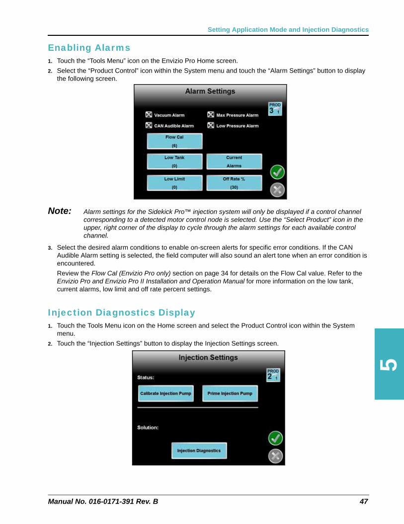
Enabling Alarms1. Touch the “Tools Menu” icon on the Envizio Pro Home screen.
2. Select the “Product Control” icon within the System menu and touch the “Alarm Settings” button to display the following screen.
Note: Alarm settings for the Sidekick Pro™ injection system will only be displayed if a control channel corresponding to a detected motor control node is selected. Use the “Select Product” icon in the upper, right corner of the display to cycle through the alarm settings for each available control channel.
3. Select the desired alarm conditions to enable on-screen alerts for specific error conditions. If the CAN Audible Alarm setting is selected, the field computer will also sound an alert tone when an error condition is encountered.
Review the Flow Cal (Envizio Pro only) section on page 34 for details on the Flow Cal value. Refer to the Envizio Pro and Envizio Pro II Installation and Operation Manual for more information on the low tank, current alarms, low limit and off rate percent settings.
Injection Diagnostics Display1. Touch the Tools Menu icon on the Home screen and select the Product Control icon within the System
menu.
2. Touch the “Injection Settings” button to display the Injection Settings screen.
Manual No. 016-0171-391 Rev. B 47

Chapter 5
Prime Injection Pump
Touch the “Prime Injection Pump” button to prime the injection pump. The Envizio Pro will stop the pump when the system detects the pump has been primed.
Calibrate Injection Pump
Touch the “Calibrate Injection Pump” button to start the injection pump calibration process.
Note: The injection pump must be primed before starting a pump calibration.
Injection Diagnostics
Touch the “Injection Diagnostics” button to view diagnostic information for the selected injection pump.
Injection Pressure. These values are the pressure observed during the pressure stroke of the left and right pump heads.
Flow/Encoder Ratio. The flow to encoder ratio is a tool used in conjunction with the Flow Cal to identify the relative efficiency of the pump. This area displays a value between 0 and 100.
Note: This number is an indicator of pump health and cannot be used to meter flow from the pump.
Motor RPM. The current RPM of the injection pump motor is displayed in the lower portion of the Injection Settings screen.
Voltage. The high current voltage detected by the CAN motor control node is displayed in this area.
PWM Percent. The percent PWM value may be used to determine how hard the pump is being driven. A value of 100 indicates the pump is being driven at the maximum.
Node Temperature. The temperature of the motor control node is displayed in this area. This value, in conjunction with the motor RPM, may be useful to help determine how hard the pump is being driven.
Application Runtime. The total run time of the selected injection pump is displayed in this area.
48 Sidekick Pro™ Installation & Operation Manual

5
Setting Application Mode and Injection Diagnostics
SCS 4000/5000 SeriesNote: Raven Sidekick Pro injection pumps (P/N 063-0173-081 or 063-0173-103) are equipped with
diagnostic and flow monitoring features for CANbus control consoles. To access complete diagnostic capabilities for the Sidekick Pro injection system, the SCS controller must have software version 1.90 or newer. Software updates for the control console may be downloaded from the Raven Applied Technology Division web site:
www.ravenhelp.com
SCS 4000/5000 Series consoles with software versions older than 1.90 will still operate with Sidekick Pro, however, the diagnostic capabilities of the console will not be available.
Application Mode Setup1. Press the DATA MENU button until the Product submenu is displayed on the screen.
2. Use the up or down arrows to select the Max PSI Err option and use the CE key to toggle the Maximum pressure alarm on or off.
3. Use the up or down arrows to select the Low PSI Err option and use the CE key to toggle the Low pressure alarm on or off.
4. Use the up or down key to select the Vacuum or Bin Level Alarm to receive an audible alarm if the system detects a vacuum error condition with the injection system.
5. When enabled, the Agitator option will send power to an agitator motor via the CAN motor control cable. See Figure 10 on page 24.
6. To enable the ratio rate application mode, press the DATA MENU button until the Console submenu is displayed on the screen and select the ratio rate option.
Injection Diagnostics Display
Press the DATA MENU key until the Run Time Diagnostics screen is displayed.
Press - PSI. These values are the pressure observed during the pressure stroke of the left and right pump heads.
PROD NODE 2-INJECTIONRUN TIME INFO
PUMP-PRESS 12.0FER 99.5MOTOR RPM 107TEMP 99.3VOLTAGE 14.2% PWM 87.5HOURS 23.6
FLOW ERROR CODE #
KEY 1 - START CALKEY 2 - START PRIMING
Manual No. 016-0171-391 Rev. B 49

Chapter 5
Vacuum - PSI. These values are the pressure observed during the vacuum stroke of the left and right pump heads.
FER. The FER (flow to encoder ratio) value is a tool used in conjunction with the FER Error Cal to identify the relative efficiency of the pump. This area displays a value between 0 and 100.
Note: This number is an indicator of pump health and cannot be used to meter flow from the pump.
Motor RPM. The current RPM of the injection pump motor is displayed in this area.
Temperature. The temperature of the motor control node is displayed in this area. This value, in conjunction with the motor RPM, may be useful to help determine how hard the pump is being driven.
Voltage. The high current voltage detected by the CAN motor control node is displayed in this area.
% PWM. The percent PWM value may be used to determine how hard the pump is being driven. A value of 100 indicates the pump is being driven at the maximum.
Hours. This value represents the number of hours which the injection node has been engaged for operation.
50 Sidekick Pro™ Installation & Operation Manual
CHAPTER
6
Manual No. 016-0171-391 Rev. B
Chapter 6System Maintenance
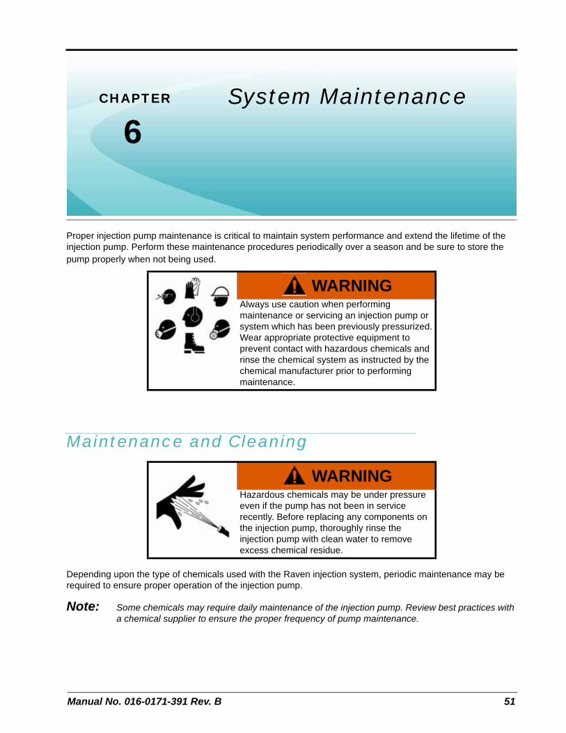
Proper injection pump maintenance is critical to maintain system performance and extend the lifetime of the injection pump. Perform these maintenance procedures periodically over a season and be sure to store the pump properly when not being used.
Maintenance and Cleaning
Depending upon the type of chemicals used with the Raven injection system, periodic maintenance may be required to ensure proper operation of the injection pump.
Note: Some chemicals may require daily maintenance of the injection pump. Review best practices with a chemical supplier to ensure the proper frequency of pump maintenance.
WARNINGAlways use caution when performing maintenance or servicing an injection pump or system which has been previously pressurized. Wear appropriate protective equipment to prevent contact with hazardous chemicals and rinse the chemical system as instructed by the chemical manufacturer prior to performing maintenance.
WARNINGHazardous chemicals may be under pressure even if the pump has not been in service recently. Before replacing any components on the injection pump, thoroughly rinse the injection pump with clean water to remove excess chemical residue.
51

Chapter 6
Check Valve O-Rings
Small particles of rust, sand, or grit may build up around the check valve seals. Over time, this may cause a noticeable decrease in the accuracy of injected product application rates. Clean or replace the o-ring seals periodically to ensure accuracy of the injection system.
1. Empty and rinse product from the chemical supply tank and flush the injection pump with water.
2. Carefully remove the intake and discharge valve cartridges from the injection pump using a 9/16” allen wrench.
Note: The intake and discharge valve assemblies contain parts which are not interchangeable. To ensure proper re-assembly, it is recommended that the intake and discharge valve assemblies are cleaned and inspected separately.
3. Examine the valve assembly o-ring and replace if cut or nicked. These o-rings are made of a chemical resistant compound and should only be replaced with o-rings supplied by a local Raven dealer.
4. Disassemble the check valve assemblies as shown in Figure 1 below.
Note: Valve assembly contains tension springs and small parts. To prevent the loss of parts, place the valve assembly inside a clear plastic bag while disassembling.
5. Examine the guide, spring, poppet and poppet o-ring for wear, pitting, swelling or foreign matter. Clean or replace if necessary. O-rings inside valve assembly are made of a chemical resistant compound and should only be replaced with o-rings supplied by a local Raven dealer.
6. Reassemble the intake and discharge plugs as shown in Figure 1 on page 53.
7. Apply petroleum jelly to valve body o-rings and replace valve assemblies into the pump head and tighten valve plug.
CAUTIONValve assembly contains small parts and springs under compression. Wear safety glasses when maintaining or cleaning valve assemblies.
Chemical residue and build up may be present on internal pump components. Wear gloves when servicing internal pump assemblies.
52 Sidekick Pro™ Installation & Operation Manual

6
System Maintenance
FIGURE 1. Check Valve Assemblies
Item Description Raven P/N Item Description Raven P/N
1 Fitting, Plug 107-0171-519 1 Fitting, Plug 107-0171-519
2 O-Ring 219-0002-912 2 O-Ring 219-0002-912
3 Guide, Poppet 107-0159-934 3 Retainer, Intake 107-0171-459
4 Spring 314-0000-006 4 Spring 314-0000-005
5 Poppet 107-0159-935 5 Guide, Poppet 107-0171-092
6 O-Ring (Viton) 219-0007-011a
a. O-Rings included in Pump Seal Kit (P/N 117-0159-987)
6 Stem, Poppet 107-0171-447
7 Clip, Retainer 107-0171-576 7 O-Ring (Viton) 219-0007-011a
8 Valve Body, Discharge 106-0159-621 8 Clip, Retainer 107-0171-576
9 O-Ring (Viton) 219-0002-018a 9 Valve, Body Intake 106-0159-622
10 O-Ring (Viton) 219-0002-018a
Intake Valve Assembly(P/N 063-0172-503)
Discharge Valve Assembly(P/N 063-0172-504)
1. Push Down
2. Rotate 90°
3. Lift Up
Spring Retainer(item 3)
Manual No. 016-0171-391 Rev. B 53

Chapter 6
Pump Cam and Bearing
Chemicals may seep into the bearing cavity. The pump cam and bearing housing should be cleaned and inspected periodically to prevent maintenance issues.
1. Loosen the four socket head screws holding the pump head to the motor assembly.
2. Remove pump from motor and clean surfaces of cam and bearing.
3. Examine the sealed bearing. If the bearing does not turn freely or smoothly, replace the bearing.
4. Apply a heavy coating of automotive grease to the area where the piston engages the cam bearing and reassemble pump to motor.
Piston Seal Replacement
The piston seals within the injection pump motor housing should be replaced periodically to keep chemical from seeping into the pump housing. The piston seals should be serviced or replaced If chemical begins leaking from the weep hole on the underside of the pump housing.
Note: New piston seals are supplied in the Pump Seal Kit (P/N 117-0159-987) available through a local Raven dealer.
CAUTIONChemical residue or build up may be present on internal pump components. Wear gloves when servicing internal pump assemblies.
CAUTIONChemical residue or build up may be present on internal pump components. Wear gloves when servicing internal pump assemblies.
54 Sidekick Pro™ Installation & Operation Manual

6
System Maintenance
FIGURE 2. Pump Head and Motor Separation (D/N 063-0173-081)
Intake Valve Assembly(P/N 063-0172-503)See Figure 1 on page 53
Discharge Valve Assembly(P/N 063-0172-504)See Figure 1 on page 53
Torque to 41 in/lbs. (4 places)
Cam Bearing Assembly(P/N 063-0172-501)
Manual No. 016-0171-391 Rev. B 55

Chapter 6
FIGURE 3. Pump Head Parts and Seal Installation (D/N 063-0173-081)
1. Empty product from the chemical supply tank and flush the injection pump with water.
2. Disconnect the injection pump plumbing and cabling. Remove the injection pump from the implement and take to a suitable work area to perform maintenance.
3. Separate the pump from the motor by removing the four socket head screws.
4. Loosen the four socket head screws securing each pump head to the crank case.
5. Carefully remove the pump heads. While removing the pump heads, take care not to damage the exposed finish on the piston during disassembly.
6. Remove the slipper seals and o-rings from the pump.
Note: During removal of the piston, the slipper seal and o-rings may stick within the pump housing. Be sure to remove and inspect both of the two slipper seals and two o-rings used with the piston.
The seals and o-rings are made of a chemical resistant compound and should only be replaced with o-rings supplied by a local Raven dealer.
7. Inspect the piston for scratches. If the finish is scratched or damaged, replace the piston.
8. Inspect the piston bearing for wear and replace if necessary.
9. Replace the seals and o-rings into the pump housing:
Note: Complete one side of the piston and head assembly before starting on the other side.
a. Install the slipper seal onto the piston.
b. Using general purpose grease, lubricate the o-ring and seat over the slipper seal.
Item Description Raven P/N Qt.
1 O-Ring, Viton 219-0002-015 4
2 O-Ring, Compound 117965-80 219-0007-117 2
3 Seal, 3/4” Slipper 219-0000-125 2
Piston Bearing (2 Places)
1(4 Places)
Torque to 41 in/lbs. (17 places)
Piston
2(2 Places)
3(2 Places)
56 Sidekick Pro™ Installation & Operation Manual

6
System Maintenance
c. Replace pump head o-rings into pump heads. If the o-rings tend to slip before the head is installed, use a small amount of additional grease on the o-ring to help hold it in place.
d. Install the pump head to the pump assembly.
e. Repeat the above steps to install the remaining pump head.
10. Tighten socket head screws to the torque specified in Figure 3 on page 56.
Seasonal Maintenance and Storage
Perform the following procedure before storing the injection pump for long periods:
Note: Failure to perform seasonal maintenance may result in damage to injection system or reduce the working life of the injection pump.
1. Empty product from the chemical supply tank and flush the injection pump with water.
2. Remove hardened chemical residues or build up by flushing the injection system with:
a. kerosene or fuel oil if the last product through the pump was petroleum based.
b. soap and water if the last product through the pump was water based.
3. Remove the intake and discharge valve assemblies from the pump.
4. Remove the pressure transducer and clean the cavity and transducer body of excess build up.
5. Clean and inspect each assembly as instructed in the Check Valve O-Rings section on page 52.
Note: Be sure to reinstall the intake and discharge valves into the correct ports on the injection pump.
6. Perform the procedure described in the Pump Cam and Bearing section on page 54 to service the cam and bearing.
7. Recirculate a 50% water and automotive antifreeze mixture through the injection pump to check pump operation after reassembly as well as prevent freezing of pump components.
WARNINGAlways use caution when performing maintenance or servicing an injection pump or system which has been previously pressurized. Wear appropriate protective equipment to prevent contact with hazardous chemicals and rinse the chemical system as instructed by the chemical manufacturer prior to performing maintenance.
CAUTIONChemical residue or build up may be present on internal pump components. Wear gloves when servicing internal pump assemblies.
Manual No. 016-0171-391 Rev. B 57

Chapter 6
58 Sidekick Pro™ Installation & Operation Manual

CHAPTER
7
Manual No. 016-0171-391 Rev. B
Chapter 7Troubleshooting
Motor Control Node LED Status IndicatorsThe Sidekick Pro integrated motor control node displays the status of the injection pump with the following node status indicators.
FIGURE 1. LED Status Indicators
Cal Switch State
Calibration Switch
Flow Switch State
CAN Status
High Current Power
Logic Power
59

Chapter 7
TABLE 1. LED Status Indicators
AlarmsTABLE 2. Sidekick Pro Error Codes for Viper Pro and Envizio Pro
LED Status Display
Logic PowerIf logic power is present at the motor control node, the logic power indicator will be on.
High Current PowerIf high current power is present at the motor control node, the high current power indicator will be on.
CAN StatusThe CAN status indicator will flash once per second if the motor control node is communicating on the CANbus. If the motor control node cannot communicate via the CANbus, the CAN status indicator will flash four times per second.
Flow Switch State The flow switch indicator will flash once per revolution of the injection pump shaft.
Calibration Switch StateThe calibration switch indicator will flash when a metal object is passed by the calibration switch sensor.
Error Description Possible Cause Solution
Off Rate Alarm
• Difference between actual and target application rates has been greater than 28% for more than 5 seconds
• Required flow rate is out of range for the injection pump. Calculate the volume per minute required for the application and verify rate is within range of the injection pump.
Low Tank Alarm• Chemical supply tank is below the refill threshold level
• Refill injection chemical supply tank and reset tank level in VT display.
Flow Error Alarm
• Flow obstruction in inlet cartridges
• Perform a pump calibration test. If the pump does not calibrate properly, remove the intake cartridges and perform pump maintenance to clear obstructions.
• Chemical supply tank is out of chemical
• Refill chemical supply tank and perform the pump priming procedure.
Flow Error Alarm • Flow obstruction in discharge cartridges
• Perform a pump calibration test. If the pump does not calibrate properly, remove the discharge cartridges and perform pump maintenance to clear obstructions.
Low Pressure Alarm• Injection pressure is lower than carrier pressure
• Perform a pump calibration test. If the pump does not calibrate properly, clean the injection pump inlet and discharge valves.
• Calibrate the pump transducer.
• Check lines between injection pump and in-line mixer.
• Verify all hand valves are in the correct position.
• Replace the pump transducer.
Maximum Vacuum Alarm
• Clogged pump strainer
• Clean pump strainer and check for obstructions in injection line between the pump inlet and chemical supply tank.
• Tubing or plumbing size restriction
• Verify the proper size of injection supply tubing is used between the chemical supply tank and pump inlet.
• Chemical too thick• Dilute product in chemical supply tank. Some chemicals may not be applied using a direct injection system.
60 Sidekick Pro™ Installation & Operation Manual

Troubleshooting
7
Maximum Pressure Alarm
• Clogged or restricted pump outlet supply lines
• Check for restrictions or blockages in outlet supply lines. Flush the injection system to clear clogs and residue buildup.
• Tubing or plumbing size restriction • Verify the proper size of injection outlet tubing is used
between the point of injection and pump outlet.• Faulty PSI transducer
• Hand valve closed• Check hand valves are open and allow flow from the injection pump outlet port.• Low injection
pressure
Pressure Sensor Alarm
• Boom pressure transducer not connected
• If installed, check that the boom pressure transducer is installed and properly connected.
• Faulty boom pressure transducer • Replace boom pressure transducer.
Motor/Encoder Alarm
• No power to pump motor
• Verify that the high current LED on the injection pump node is lit.
• Pump motor or encoder issue
• Check motor and encoder connections. Disconnect the injection pump node from the pump motor and check that the motor and encoder connections are seated properly. If these connections appear solid, return pump to a local Raven dealer for service.
HC Power Alarm• Injection node not connected to high current power
• Verify high current breaker is not tripped.
• Verify battery connections.
Zero Speed Alarm• Faulty cabling, connection or speed sensor.
• Verify speed sensor and signal. Refer to the field computer operation manual for information on testing speed and flow cabling and troubleshooting the speed sensor.
Low Limit Alarm • •
Error Description Possible Cause Solution
Manual No. 016-0171-391 Rev. B 61

Chapter 7
62 Sidekick Pro™ Installation & Operation Manual
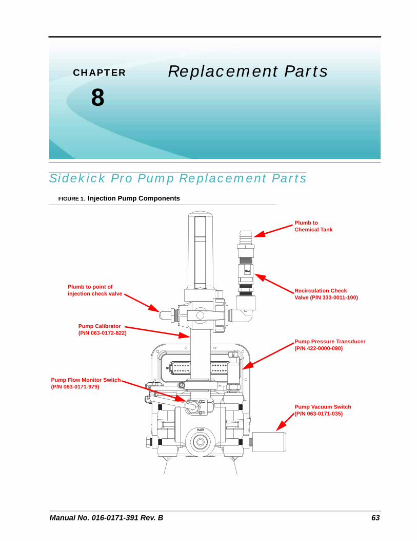
CHAPTER
8
Manual No. 016-0171-391 Rev. B
Chapter 8Replacement Parts
Sidekick Pro Pump Replacement PartsFIGURE 1. Injection Pump Components
Plumb to point of injection check valve
Pump Flow Monitor Switch (P/N 063-0171-979)
Plumb to Chemical Tank
Recirculation Check Valve (P/N 333-0011-100)
Pump Pressure Transducer (P/N 422-0000-090)
Pump Vacuum Switch (P/N 063-0171-035)
Pump Calibrator(P/N 063-0172-822)
63

Chapter 8
Injection Pump Pressure Transducer
To replace the pressure transducer (P/N 422-0000-090):
1. Disable and shutdown any automatic product control features of the Sidekick Pro injection system and turn off the vehicle when replacing the pressure transducer assembly.
2. Disconnect the pressure transducer connector on the top of the pressure transducer body. Be careful to keep dust, debris, or liquid chemicals which may seep from the injection pump head from contaminating the cable connection.
3. Loosen the pressure transducer while securing the connected fitting to prevent damage to the pump head.
4. Apply RectorSeal® or equivalent thread sealant to the new pressure transducer and thread into the pump head.
5. Tighten the pressure transducer body two or three quarter turns to secure the pressure transducer.
Note: Do not over tighten the pressure transducer. Overtightening the pressure transducer may damage the pump head.
Calibrating the Pump Transducer
Note: The following process offers a general overview of calibrating or resetting the Sidekick Pro pump pressure transducer Refer to the operation manual for the specific control console for detailed navigation and calibration of the pressure transducer or pressure display.
1. Select or display the set up screens for the correct product.
2. Turn off the injection pump and product control system and ensure no product pressure in the injection lines.
3. Enter a value of zero for the pressure calibration value.
WARNINGAlways use caution when performing maintenance or servicing an injection pump or system which has been previously pressurized. Wear appropriate protective equipment to prevent contact with hazardous chemicals and rinse the chemical system as instructed by the chemical manufacturer prior to performing maintenance.
WARNINGHazardous chemicals may be under pressure even if the pump has not been in service recently. Before replacing any components on the injection pump, thoroughly rinse the injection pump with clean water to remove excess chemical residue.
64 Sidekick Pro™ Installation & Operation Manual

8
Replacement Parts
Injection Pump Vacuum Switch
To replace the vacuum switch (P/N 063-0171-035):
1. Disable and shutdown any automatic product control features of the Sidekick Pro injection system and turn off the vehicle when replacing the vacuum switch assembly.
2. Disconnect the vacuum switch connector from the motor control cabling. Be careful to keep dust, debris, or liquid chemicals which may seep from the injection pump head from contaminating the cable connections.
3. Loosen the vacuum switch while securing the connected fitting to prevent damage to the pump head.
4. Apply RectorSeal® or equivalent thread sealant to the new vacuum switch and thread into the pump head.
5. If necessary, slide the protective covering on the vacuum switch back slightly to expose the hex surface for tightening the vacuum switch body.
6. Tighten the vacuum switch body two or three quarter turns to secure the vacuum switch.
Note: Do not over tighten the pressure transducer. Overtightening the pressure transducer may damage the pump head.
7. Be sure to replace the protective cover over the flow switch before operating the pump.
WARNINGAlways use caution when performing maintenance or servicing an injection pump or system which has been previously pressurized. Wear appropriate protective equipment to prevent contact with hazardous chemicals and rinse the chemical system as instructed by the chemical manufacturer prior to performing maintenance.
WARNINGHazardous chemicals may be under pressure even if the pump has not been in service recently. Before replacing any components on the injection pump, thoroughly rinse the injection pump with clean water to remove excess chemical residue.
Manual No. 016-0171-391 Rev. B 65

Chapter 8
Injection Pump Flow Monitor Sensor
Perform the following procedure to replace the flow monitor sensor (P/N 063-0171-979).
FIGURE 2. Pump Head and Flow Monitor Sensor
1. Disconnect the sensor cable from the motor control cabling.
2. Loosen the locking nut on the switch assembly and remove the old sensor assembly from the pump head.
3. Loosen the sensor bracket mounting screws enough to allow the bracket to slide freely on the pump head.
Note: It is recommended to replace the sensor bracket if an updated flow monitor sensor is supplied with a new bracket and mounting hardware. The updated flow sensor is designed to improve flow sensitivity while the updated sensor bracket and hardware will help to secure the sensor body properly in the pump head.
FIGURE 3. Flow Sensor Update Kit (P/N 117-0171-455) with Bracket and Hardware
Remove the existing allen screws and sensor bracket. Loosely mount the supplied bracket to the pump head using the supplied washers and allen screws. The updated flow monitor sensor and bracket should be mounted to the pump head as shown in Figure 3 above.
Pump Inlet Port
Sensor Bracket and Screws
Updated Sensor Bracket
Updated Pump Flow Monitor Sensor
Stainless Steel Flat Washer
66 Sidekick Pro™ Installation & Operation Manual
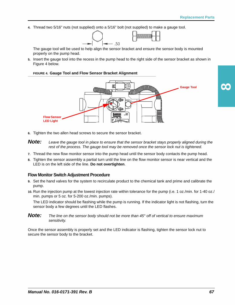
8
Replacement Parts
4. Thread two 5/16” nuts (not supplied) onto a 5/16” bolt (not supplied) to make a gauge tool.
The gauge tool will be used to help align the sensor bracket and ensure the sensor body is mounted properly on the pump head.
5. Insert the gauge tool into the recess in the pump head to the right side of the sensor bracket as shown in Figure 4 below.
FIGURE 4. Gauge Tool and Flow Sensor Bracket Alignment
6. Tighten the two allen head screws to secure the sensor bracket.
Note: Leave the gauge tool in place to ensure that the sensor bracket stays properly aligned during the rest of the process. The gauge tool may be removed once the sensor lock nut is tightened.
7. Thread the new flow monitor sensor into the pump head until the sensor body contacts the pump head.
8. Tighten the sensor assembly a partial turn until the line on the flow monitor sensor is near vertical and the LED is on the left side of the line. Do not overtighten.
Flow Monitor Switch Adjustment Procedure9. Set the hand valves for the system to recirculate product to the chemical tank and prime and calibrate the
pump.
10. Run the injection pump at the lowest injection rate within tolerance for the pump (i.e. 1 oz./min. for 1-40 oz./min. pumps or 5 oz. for 5-200 oz./min. pumps).
The LED indicator should be flashing while the pump is running. If the indicator light is not flashing, turn the sensor body a few degrees until the LED flashes.
Note: The line on the sensor body should not be more than 45° off of vertical to ensure maximum sensitivity.
Once the sensor assembly is properly set and the LED indicator is flashing, tighten the sensor lock nut to secure the sensor body to the bracket.
Gauge Tool
Flow Sensor LED Light
Manual No. 016-0171-391 Rev. B 67
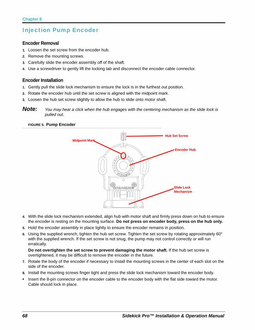
Chapter 8
Injection Pump Encoder
Encoder Removal1. Loosen the set screw from the encoder hub.
2. Remove the mounting screws.
3. Carefully slide the encoder assembly off of the shaft.
4. Use a screwdriver to gently lift the locking tab and disconnect the encoder cable connector.
Encoder Installation1. Gently pull the slide lock mechanism to ensure the lock is in the furthest out position.
2. Rotate the encoder hub until the set screw is aligned with the midpoint mark.
3. Loosen the hub set screw slightly to allow the hub to slide onto motor shaft.
Note: You may hear a click when the hub engages with the centering mechanism as the slide lock is pulled out.
FIGURE 5. Pump Encoder
4. With the slide lock mechanism extended, align hub with motor shaft and firmly press down on hub to ensure the encoder is resting on the mounting surface. Do not press on encoder body, press on the hub only.
5. Hold the encoder assembly in place lightly to ensure the encoder remains in position.
6. Using the supplied wrench, tighten the hub set screw. Tighten the set screw by rotating approximately 60° with the supplied wrench. If the set screw is not snug, the pump may not control correctly or will run erratically.
Do not overtighten the set screw to prevent damaging the motor shaft. If the hub set screw is overtightened, it may be difficult to remove the encoder in the future.
7. Rotate the body of the encoder if necessary to install the mounting screws in the center of each slot on the side of the encoder.
8. Install the mounting screws finger tight and press the slide lock mechanism toward the encoder body.
• Insert the 8-pin connector on the encoder cable to the encoder body with the flat side toward the motor. Cable should lock in place.
Encoder Hub
Midpoint Mark
Slide Lock Mechanism
Hub Set Screw
68 Sidekick Pro™ Installation & Operation Manual
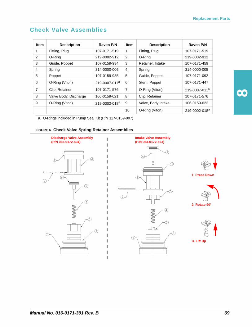
8
Replacement Parts
Check Valve Assemblies
FIGURE 6. Check Valve Spring Retainer Assemblies
Item Description Raven P/N Item Description Raven P/N
1 Fitting, Plug 107-0171-519 1 Fitting, Plug 107-0171-519
2 O-Ring 219-0002-912 2 O-Ring 219-0002-912
3 Guide, Poppet 107-0159-934 3 Retainer, Intake 107-0171-459
4 Spring 314-0000-006 4 Spring 314-0000-005
5 Poppet 107-0159-935 5 Guide, Poppet 107-0171-092
6 O-Ring (Viton) 219-0007-011a
a. O-Rings included in Pump Seal Kit (P/N 117-0159-987)
6 Stem, Poppet 107-0171-447
7 Clip, Retainer 107-0171-576 7 O-Ring (Viton) 219-0007-011a
8 Valve Body, Discharge 106-0159-621 8 Clip, Retainer 107-0171-576
9 O-Ring (Viton) 219-0002-018a 9 Valve, Body Intake 106-0159-622
10 O-Ring (Viton) 219-0002-018a
Intake Valve Assembly(P/N 063-0172-503)
Discharge Valve Assembly(P/N 063-0172-504)
1. Press Down
2. Rotate 90°
3. Lift Up
Manual No. 016-0171-391 Rev. B 69

Chapter 8
Sidekick Pro™ 1 to 40 oz./min. PumpTABLE 1. Injection Pump (P/N 063-0173-103) Replacement Parts
70 Sidekick Pro™ Installation & Operation Manual

8
Replacement Parts
FIGURE 7. CAN Integrated Pump (P/N 063-0173-103) Housing and Encoder
Manual No. 016-0171-391 Rev. B 71

Chapter 8
FIGURE 8. CAN Integrated Pump (P/N 063-0173-103) Pump Head and Mounting Bracket
72 Sidekick Pro™ Installation & Operation Manual

8
Replacement Parts
Sidekick Pro™ 5 to 200 oz./min. PumpTABLE 2. CAN Integrated Injection Pump (P/N 063-0173-081) Replacement Parts
Manual No. 016-0171-391 Rev. B 73

Chapter 8
FIGURE 9. CAN Integrated Pump (P/N 063-0173-081) Housing and Encoder
74 Sidekick Pro™ Installation & Operation Manual

8
Replacement Parts
FIGURE 10. CAN Integrated Pump (P/N 063-0173-081) Pump Head and Mounting Bracket
Manual No. 016-0171-391 Rev. B 75

Chapter 8
Sidekick Pro Module Replacement Parts
Modules with 24 Gallon Tank and 1 to 40 oz./min. PumpTABLE 3. Injection Module (P/N 063-0173-212) Replacement Parts(24 Gallon Chemical Tank, 1 to 40 oz./min. Pump)
76 Sidekick Pro™ Installation & Operation Manual

8
Replacement Parts
FIGURE 11. Injection Module (P/N 063-0173-212) Plumbing and Valves
Manual No. 016-0171-391 Rev. B 77

Chapter 8
FIGURE 12. Injection Module (P/N 063-0173-212) Final Plumbing and Mounting
78 Sidekick Pro™ Installation & Operation Manual

8
Replacement Parts
FIGURE 13. Injection Module (P/N 063-0173-212) Module Mounting
Manual No. 016-0171-391 Rev. B 79
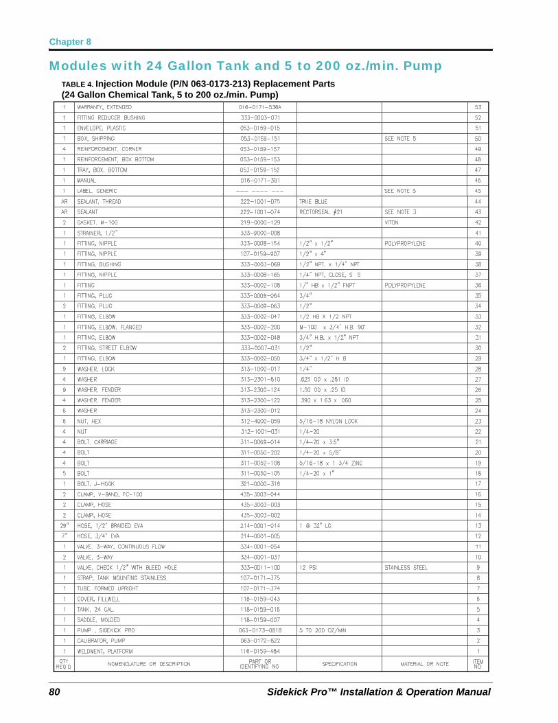
Chapter 8
Modules with 24 Gallon Tank and 5 to 200 oz./min. PumpTABLE 4. Injection Module (P/N 063-0173-213) Replacement Parts(24 Gallon Chemical Tank, 5 to 200 oz./min. Pump)
80 Sidekick Pro™ Installation & Operation Manual

8
Replacement Parts
FIGURE 14. Injection Module (P/N 063-0173-213) Plumbing and Valves
Manual No. 016-0171-391 Rev. B 81

Chapter 8
FIGURE 15. Injection Module (P/N 063-0173-213) Final Plumbing and Mounting
82 Sidekick Pro™ Installation & Operation Manual

8
Replacement Parts
FIGURE 16. Injection Module (P/N 063-0173-213) Module Mounting
Manual No. 016-0171-391 Rev. B 83

Chapter 8
84 Sidekick Pro™ Installation & Operation Manual
CHAPTER
9
Manual No. 016-0171-391 Rev. B
Chapter 9System Diagrams
Refer to the following diagrams for connecting a Raven injection system to a new or existing CANbus product control system.
85

Chapter 9
FIGURE 1. Sidekick Pro with Envizio Pro Liquid Product Control System (D/N 054-2000-006)
86 Sidekick Pro™ Installation & Operation Manual

9
System Diagrams
FIGURE 2. Sidekick Pro with Viper Pro Liquid Product Control System (D/N 054-2140-007)
Manual No. 016-0171-391 Rev. B 87

Chapter 9
FIGURE 3. Sidekick Pro with SCS 4400 Liquid Product Control System (D/N 054-2840-009)
88 Sidekick Pro™ Installation & Operation Manual

Index
AApplication Mode Setup 43
Envizio Pro 45SCS 4000/5000 Series 48Viper Pro 43
Application Modes 35Normal 36Ratio Rate 37
BBest Installation Practices 22, 25
CCalibration and Operation 31
Console Calibration 31FER Cal (SCS 4000/5000 Series and Viper Pro
only) 34Flow Cal (Envizio Pro only) 34Meter Cal 33Rate Cal 33Valve Type and Valve Cal 33
CAN (Controller Area Network)Addressing the Motor Control Node 29
Alternate Method 29Best Installation Practices 22, 25CANbus and Power Connections 22Detecting the Motor Control Node 29Sidekick Pro Pump 28Terminators 22, 25
Control Features 35Agitator 37Flow Monitor Features 37
FFeatures 4
Closed Calibration System 4Integrated Motor Control Node 5System Diagnostics 6
IImportant Safety Information 1
Chemical Handling and Safety 1Electrical Safety 2
Injection Diagnostics 43Envizio Pro 47SCS 4000/5000 Series 49Viper Pro 44
InstallationChemical Tank 16Initial Plumbing and Point of Injection 12Injection Module 15Overview 11Sidekick Pro Pump 16Verifying Sidekick Pro 29
MMaintenance 51
Seasonal Maintenance and Storage 57Modes.See Application Modes 36
OOverview 3
Injection System Components 3
PPlumbing 18
Closed Calibration System 19Recommended Pump Rinse System 20Sidekick Pro Pump 18
Power Connections 22
RReplacement Parts 63
Check Valve Assemblies 69Injection Pump Encoder 67Injection Pump Flow Switch 65Injection Pump Pressure Transducer 64Sidekick Pro Module 76Sidekick Pro Pump 63
SSidekick Pro Priming and Calibration 37
Calibrate the Injection Pump 39Prime the Injection Pump 38Verify Control Console 38
Specifications 6
TTroubleshooting
Alarms 60Motor Control Node LED Status Indicators 59
VVerifying Installation of the Sidekick Pro 29
Manual No. 016-0171-391 89

Index
90 Sidekick Pro™ Installation & Operation Manual

Raven Industries will not assume any expense or liability for repairs made outside our facilities without written consent. Raven Industries is not responsible for damage to any associated equipment or products and will not be liable for loss of profit, labor, or other damages. The obligation of this warranty is in lieu of all other warranties, expressed or implied, and no person or organization is
authorized to assume any liability for Raven Industries.
Damages caused by normal wear and tear, misuse, abuse, neglect, accident, or improper installation and maintenance are
not covered by this warranty.
What is not Covered by this Warranty?
Upon confirmation of the warranty claim, Raven Industries will (at our discretion) repair or replace the defective product and pay for the standard return freight, regardless of the inbound shipping method.
Expedited freight is available at the customer’s expense.
What Will Raven Industries Do?
Bring the defective part and proof of purchase to your Raven dealer.If the dealer approves the warranty claim, the dealer will process the claim and send it to Raven Industries for final approval. The freight cost to Raven Industries will be the customer’s responsibility. The Return Materials Authorization (RMA) number must appear on the box and all documentation (including proof of purchase) must be included inside
the box to be sent to Raven Industries.
How Can I Get Service?
Raven Applied Technology products are covered by this warranty for 12 months from the date of retail sale. In no case will the Limited Warranty period exceed 24 months from the date the product was issued by Raven Industries Applied Technology Division. This warranty coverage
applies only to the original owner and is non-transferable.
How Long is the Coverage Period?
This warranty covers all defects in workmanship or materials in your Raven Applied Technology Division product under normal use,
maintenance, and service when used for intended purpose.
What Does this Warranty Cover?
Limited Warranty
016-0171-537 Rev. A, E19889

Raven Applied Technology products that have been registered online are covered for an additional 12 months beyond the Limited Warranty for a total coverage period of 24 months from the date of retail sale. In no case will the Extended Warranty period exceed 36 months from the date the product was issued by Raven Industries Applied Technology Division. This Extended Warranty coverage applies only to the
original owner and is non-transferable.
How Long is the Extended Warranty Coverage Period?
To register, go online to www.ravenhelp.com and select Product Registration.Where Can I Register My Product for the Extended Warranty?
Yes. Products/systems must be registered within 30 days of retail sale to receive coverage under the Extended Warranty. If the component does not have a serial
tag, the kit it came in must be registered instead.
Do I Need to Register My Product to Qualify for the Extended Warranty?
This warranty covers all defects in workmanship or materials in your Raven Applied Technology Division product under normal use, maintenance, and service when
used for intended purpose.
What Does this Warranty Cover?
Bring the defective part and proof of purchase to your Raven dealer. If the dealer approves the warranty claim, the dealer will process the claim and send it to Raven Industries for final approval. The freight cost to Raven Industries will be the customer’s responsibility. The Return Materials Authorization (RMA) number must appear on the box and all documentation (including proof of purchase) must be included inside the box to be sent to Raven Industries. In addition, the words “Extended Warranty” must appear on the box and all documentation if the failure is
between 12 and 24 months from the retail sale.
How Can I Get Service?
Upon confirmation of the product’s registration for the Extended Warranty and the claim itself, Raven Industries will (at our discretion) repair or replace the defective product and pay for the standard return freight, regardless of the inbound shipping
method. Expedited freight is available at the customer’s expense.
What Will Raven Industries Do?
Raven Industries will not assume any expense or liability for repairs made outside our facilities without written consent. Raven Industries is not responsible for damage to any associated equipment or products and will not be liable for loss of profit, labor, or other damages. Cables, hoses, software enhancements, and remanufactured items are not covered by this Extended Warranty. The obligation of this warranty is in lieu of all other warranties, expressed or implied, and no person
or organization is authorized to assume any liability for Raven Industries.
Damages caused by normal wear and tear, misuse, abuse, neglect, accident, or improper installation and maintenance are not covered by this warranty.
What is Not Covered by the Extended Warranty?
Extended Warranty
016-0171-536 Rev. A, E19889


Notice: This document and the information provided are the property of Raven Industries, Inc. and may only be used as authorized by Raven Industries, Inc. All rights reserved under copyright laws.
Raven Industries Applied Technology Division Toll Free (U.S. and Canada): (800)-243-5435P.O. Box 5107 or Outside the U.S. :1 605-575-0722Sioux Falls, SD 57117-5107 Fax: 605-331-0426www.ravenprecision.com www.ravenhelp.com
©Raven Industries, Inc. 2010, 2012
Sidekick Pro™1 to 40 oz./min and 5 to 200 oz./min.[0.3 to 11.8 dL/min. and 1.5 to 59 dL/min.]Installation & Operation Manual(P/N 016-0171-391 Rev B 8/12 E19877)