Embed Size (px)
Citation preview

Waste Oil Furnace Models: EL-140H, EL-200H, and EL-350H
115V/60Hz
5901 Crossings Boulevard Nashville, TN 37013
www.energylogic.com (615) 471-5290
Installation & Operation Manual
Designed to save. Built to last.™
Item #: 98030028 Issue Date: 28 April 2015

Caution! Before you begin installation and operation
of your furnace, read this manual completely, and save it for future reference!
IMPROPER INSTALLATION, OPERATION, OR MAINTENANCE OF THE FURNACE SYSTEM CAN CREATE
HAZARDOUS CONDITIONS AND WILL VOID THE WARRANTY AND U.L. LISTING.
• This furnace is UL listed for commercial and industrial use only. • Refer to Section 1 for safety information and precautions. • Installation of the unit shall be made in accordance with all state and local codes which
may differ from information provided in this manual. Installations in Canada shall be in accordance with the regulations of authorities having jurisdiction and installation practice shall be made according to CSA standard B139, Installation Code for Oil Burning Equipment.
• Product improvements are occurring regularly, so the products may vary slightly from what is shown in this manual.
• If you have any questions or concerns during the installation or operation of the furnace, contact your local service representative or EnergyLogic.
Thank you for purchasing an EnergyLogic furnace. Record your Unit I.D. number below for future reference. Please register your unit to activate the warranty by visiting EnergyLogic’s website at www.energylogic.com/register . If you have any issues with registering, please contact us at 615-471-5200.
Unit I.D. #: (Six digit number located on the bottom of the furnace) Installed By: (Service Company, Address, Contact Name, Phone Number)
Date of Installation:
i Call 1-615-471-5290 for Technical Support
Table of Contents
Before you begin ................................................................................................................................... i
Table of Contents ................................................................................................................................... ii
1. Safety, Codes and Regulations ......................................................................................................... 1
1.1 Conventions Used in this Manual................................................................................................. 1
1.2 General Warnings ........................................................................................................................ 2
1.3 Safety Hazards ............................................................................................................................ 2
1.4 Codes and Regulations ............................................................................................................... 4
1.5 Fuels and Fuel Management ....................................................................................................... 5
1.5.1 Fuels ..................................................................................................................................... 5
1.6 Clearances to Combustible Surfaces ........................................................................................... 6
2. Installation Considerations ................................................................................................................ 7
2.1 Technical Guidelines ................................................................................................................... 7
2.2 Tools Required ............................................................................................................................ 8
2.3 Furnace Placement Guide ........................................................................................................... 8
3. Assembly and Installation – Cabinet, Tank, Pump and Suction Fuel Line. ...................................... 10
3.1 Unpacking and Inspection ......................................................................................................... 10
3.2 Warranty Registration ................................................................................................................ 10
3.3 Furnace Cabinet Installation – On an EL Tank .......................................................................... 12
3.3.1 Locate the EnergyLogic Used Oil Storage Tank .................................................................. 12
3.3.2 Tank Stands and Cabinet Installation (250 gallon tank shown) ............................................ 12
3.4 Furnace Cabinet Installation – Not Mounted on a Tank ............................................................. 14
3.4.1 Ceiling Mount with Threaded Rod ........................................................................................ 14
3.4.2 Wall Mount with Optional Brackets ....................................................................................... 15
3.5 Preparing the EnergyLogic Used-Oil Tank ................................................................................. 16
3.5.1 Tank Vent Installation – EnergyLogic Tanks ........................................................................ 16
3.5.2 Drain Valve Installation – EnergyLogic Tanks ..................................................................... 16
3.5.3 Low Fuel Cutoff Switch – EnergyLogic Tanks ..................................................................... 16
3.6 Fuel Metering Pump and Filter Installation – EnergyLogic Tank (continue to section 3.7 if you don’t have EL tank). .......................................................................................................................... 17
3.6.1 Fire Stop Valve and Filter Head Installation – EL Tank. ....................................................... 17
3.6.2 Metering Pump Installation – EL Tank ................................................................................. 17
ii Call 1-615-471-5290 for Technical Support
3.6.3 Gauge and Pump Tubing Installation – EL Tank ................................................................. 18
3.7 Metering Pump Installation – Non-EL Tank (skip if you have EL tank) ........................................ 19
4. Installation of Furnace Components ................................................................................................ 20
4.1 Blower Assembly Installation ..................................................................................................... 20
4.2 Burner/Preheater Assembly ....................................................................................................... 22
4.3 Burner/Cabinet Assembly .......................................................................................................... 23
4.4 Pump Outlet Tubing Installation ................................................................................................. 24
4.4.1 Pump Outlet Tubing Installation ........................................................................................... 24
4.4.2 Pump Outlet Tubing Installation – Ceiling or Wall Mounted Furnace (skip if you have a tank mounted furnace) .......................................................................................................................... 25
5. Exhaust Flue System Installation .................................................................................................... 26
5.1 Barometric Damper Tee Installation ........................................................................................... 26
5.2 Flue Piping Installation ............................................................................................................... 26
5.3 Draft Gauge Installation (included with some packages) ............................................................ 29
6. Electrical System Installation ........................................................................................................... 30
6.1 Wall Thermostat ........................................................................................................................ 30
6.2 Fuel Pump Power Connection ................................................................................................... 32
6.3 Main Electrical Connection ........................................................................................................ 33
7. Startup and Operation ..................................................................................................................... 34
7.1 Do’s and Don’ts/Tech Tips ......................................................................................................... 34
7.2 Burner Primary Control Operation.............................................................................................. 34
7.3 Safety Systems and Warnings ................................................................................................... 35
7.4 Furnace Startup ......................................................................................................................... 36
7.4.1 Fuel System Priming ........................................................................................................... 36
7.4.2 Starting the Furnace ............................................................................................................ 38
7.4.3 Burner System Checkout .................................................................................................... 39
7.5 Everyday Operation of Your EnergyLogic Used Oil Furnace ...................................................... 42
8. Maintenance ................................................................................................................................... 43
8.1 Service Contracts ...................................................................................................................... 44
8.2 Safety Warnings – Lockout/Tagout ............................................................................................ 44
8.3 Monitoring System Performance over Time ............................................................................... 44
8.4 Maintenance Schedule and Parts .............................................................................................. 44
8.5 Maintenance Procedures ........................................................................................................... 46
8.5.1 Heat Exchanger Cleaning ................................................................................................... 46
8.5.2 Blower Cleaning .................................................................................................................. 50
iii
Call 1-615-471-5290 for Technical Support
8.5.3 Fuel Oil Filter Replacement ................................................................................................. 51
8.5.4 Preheater Cleaning ............................................................................................................. 52
8.5.5 Nozzle Line Assembly Cleaning .......................................................................................... 54
8.5.6 Retention Head and Electrode Settings ............................................................................... 57
8.5.7 Solenoid Valve Cleaning ..................................................................................................... 59
8.5.8 Air Compressor Maintenance .............................................................................................. 61
8.6 Seasonal Shut Down & Start Up ................................................................................................ 63
9. Troubleshooting .............................................................................................................................. 64
9.1 Troubleshooting Condition Table ............................................................................................... 65
9.2 Troubleshooting Trees ............................................................................................................... 66
9.3 Testing Procedures ................................................................................................................... 69
9.3.1 Wall Thermostat Testing ...................................................................................................... 69
9.3.2 Blower Assembly Testing ..................................................................................................... 70
9.3.3 Cad Cell Testing................................................................................................................... 71
9.3.4 Metering Pump Assembly Testing ........................................................................................ 72
9.3.5 Preheater and Nozzle PTC Testing Procedure ..................................................................... 74
9.3.6 Primary Control Testing........................................................................................................ 76
9.3.7 Solenoid Valve Testing......................................................................................................... 77
9.3.8 Top Suction Kit Testing ........................................................................................................ 78
9.3.9 Iron Core Transformer Testing ............................................................................................. 79
9.3.10 Fan and Limit Controller Testing ........................................................................................ 81
10. Appendices ................................................................................................................................... 82
10.1 Furnace Wiring and Oil Schematic ........................................................................................... 82
10.2 Carlin 50200E Primary Control ................................................................................................ 84
10.3 Furnace Specifications ............................................................................................................ 86
10.4 Limited Warranty ..................................................................................................................... 90
iv
Call 1-615-471-5290 for Technical Support
1. Safety, Codes and Regulations Thank you for the purchase of an EnergyLogic used oil furnace. EnergyLogic furnaces are designed and tested for safe, reliable long term operation. However, proper installation, fuel quality control, and regular maintenance are required. Please read and understand this manual completely before attempting to install, operate, or service the furnace. Post this instruction manual and maintain it in legible condition. If you have any questions, call your local service provider or the number below for EnergyLogic Technical Service.
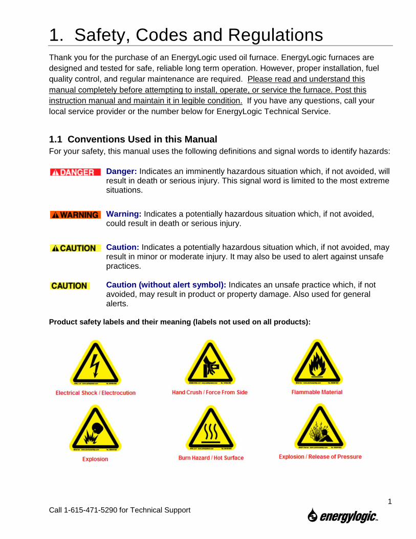
1.1 Conventions Used in this Manual For your safety, this manual uses the following definitions and signal words to identify hazards:
Danger: Indicates an imminently hazardous situation which, if not avoided, will result in death or serious injury. This signal word is limited to the most extreme situations.
Warning: Indicates a potentially hazardous situation which, if not avoided, could result in death or serious injury.
Caution: Indicates a potentially hazardous situation which, if not avoided, may result in minor or moderate injury. It may also be used to alert against unsafe practices. Caution (without alert symbol): Indicates an unsafe practice which, if not avoided, may result in product or property damage. Also used for general alerts.
Product safety labels and their meaning (labels not used on all products):
1
Call 1-615-471-5290 for Technical Support
1.2 General Warnings • The EnergyLogic burner is to be used only in the EnergyLogic furnace
provided. Do not attempt to use the burner for other purposes. • Do not tamper with the unit or controls – call your service technician. • Do not attempt to use unit with broken or damaged components. • If you are intending to use the furnace with existing building ductwork,
make sure that the requirements are met for allowable external static pressure (see specification table in appendix).
• Do not allow unqualified personnel to install or service the furnace, electrical system, or flue system. Contact EnergyLogic for help with finding a qualified installation and service company. Failure to install and maintain your heater properly will void your warranty and the UL listings.
• Do not attempt to start the burner when excess oil has accumulated, when the furnace is full of vapor, or when the combustion chamber is very hot.
• Do not start the burner unless all cleanout panels are secure in place. • KEEP THE FUEL VALVE NEAREST THE SUPPLY TANK SHUT OFF
WHEN THE BURNER IS SHUT OFF FOR EXTENDED PERIODS. • Turn off power to the burner when the burner is off for extended periods. • The furnace is designed to be installed above head height, or in a manner
that restricts access. • USED OILS CONTAIN HEAVY METALLIC COMPOUNDS AND
FOREIGN MATERIALS. WHEN BURNED, THESE COMPOUNDS ARE EMITTED FROM OR DEPOSITED WITHIN THIS HEATING APPLIANCE AND THEREFORE CARE SHOULD BE TAKEN WHEN USING, CLEANING AND MAINTAINING THIS EQUIPMENT.
• EnergyLogic recommends that the building have a secondary heat source during times the furnace is down for maintenance or service. Used oil furnaces require maintenance. Also, used oil may sometimes be unavailable or burn poorly due to contaminates in the oil. The heat from the secondary heater should be directed away from the furnace.
1.3 Safety Hazards There are potential hazards associated with operation of this or any other furnace. In addition to the codes and regulations listed in the following section, general safety rules and the precautions should be followed at all times to prevent accidents that could lead to personal injury, death or property damage. Only those qualified should perform the tasks. Specific safety hazards include:
Electricity: The EnergyLogic furnace operates on 115V/60Hz electrical power. Turn power off at the circuit breaker and lock it out prior to performing any work on the furnace
2
Call 1-615-471-5290 for Technical Support
system or any of the components. Make sure covers are in place during normal use. Use only copper conductors.
Liquid Fuels: Used oils must be handled properly to prevent spills. Uncontained oil leaks may contaminate the local water supply. Ensure that all national and local codes are followed in regards to the requirements for spill containment and SPCC paperwork. Oil leaks pose slip/fall hazards, and pose a risk for fires. DO NOT USE GASOLINE OR ANY OIL CONTAINING GASOLINE. Do not add any cleaning fluids or oil additives to the used oil burned in this appliance. The use of unauthorized fuels will void the warranty and U.L. listing. See section 1.5.1 for a list of allowable fuels. The end user of the furnace is responsible for ensuring that all correct precautions are taken in managing their used oil.
Combustion Exhaust Gases: The exhaust products from the combustion are dangerous to breathe. The furnace must be attached to a flue which properly vents the exhaust out of the building to the atmosphere at all times, to assure safe and proper operation of the burner. If proper draft cannot be established, changes to the building construction or a draft inducer will be required in order to provide adequate make-up air.
Safe Maintenance: Used oil contains mineral additives and deposits called “ash” that will not burn. Ash collects in the furnace and flue with regular use over time. Ash must be cleaned out of the combustion chamber/heat exchanger and flue pipe on a scheduled basis. Follow the minimum maintenance instructed in section 8. Wear proper protective clothing; including gloves and face mask or respirator whenever any cleaning is performed, including the cleaning of the heat exchanger, flue piping and exhaust stack.
Vapor/Dust Ignition: Do not store or use gasoline or other flammable liquids or vapors near this furnace, as they may be ignited by the burner. Do not operate the furnace in dusty or otherwise dangerous environments.
Flammable liquids: Do not create a fire or explosion hazard by using or placing flammable liquids such as gasoline or solvents near the furnace. A flammable liquid is any liquid that has a closed-cup flash point below 100°F (37.8°C), as determined by the test procedures and apparatus set forth in 1.7.4 of NFPA 30.
Minimum Clearance – Safe clearance to combustibles (Section 1.6) shall be adhered to.
Height, Weight, Guarding and General Safe Practices: The furnaces are installed at heights which pose a risk for injuries due to a fall. Many of the components are heavy, and pose the risk of injury with improper lifting and handling. Always follow safe practices and use proper equipment. Never climb on the equipment. Do not take risks when installing or servicing the equipment. All cover plates, enclosures, and guards must be maintained in place at all times, except during maintenance and servicing. Failure to observe general safety rules and to follow safety rules specific to the tools and equipment used or being worked on may result in product/property damage, personal injury or death.
3
Call 1-615-471-5290 for Technical Support
1.4 Codes and Regulations The installation, operation, and maintenance of the furnace system in the United States must be performed by qualified personnel in accordance with this manual and all national, state, and local codes / regulations, as well as the following standards of the National Fire Protection Association (NFPA):
NFPA 31 Standard for the Installation of Oil Burning Equipment NFPA 30 Flammable and Combustible Liquids Code NFPA 30A Code for Motor Fuel Dispensing Facilities and Repair Garages NFPA 70 National Electric Code NFPA 88A Standard for Parking Structures NFPA 88B Standard for Repair Garages NFPA 211 Standard for Chimneys, Fireplaces, Vents and Solid Fuel Burning
Appliances These standards are available from the NFPA at www.nfpa.org.
Similarly, the installation, operation, and maintenance of the furnace system in Canada must be performed by qualified personnel in accordance with this manual and in accordance with all the regulation authorities having jurisdiction, as well as CSA Standard B 139, Installation Code for Oil Burning Equipment. Electrical installation in Canada shall be in accordance with the Canadian Electrical Code, Part I. CSA standards are available at www.csa.ca.
A qualified installer is an individual or agency who is responsible for the installation and adjustment of the equipment and who is properly trained and licensed to install oil burning equipment in accordance with all codes and ordinances.
In the United States, make sure you comply with all EPA regulations concerning the gathering and storing of used oil, and operation of the furnace. Specifically, CFR Title 40 Part 279 covers managing used oil. As well, make sure you comply with local codes and regulations.
In Canada, only used oil generated on the premises of the owner may be used in this equipment unless written authorization is obtained from the regulatory authority. Comply with Canadian regulations regarding the management and storing of used oil, as well as any local codes and authorities having jurisdiction
4
Call 1-615-471-5290 for Technical Support
1.5 Fuels and Fuel Management The furnace system is composed of several components and subsystems that work together for efficient and safe operation. In order for the system to function as designed, good fuel management practice must be followed.
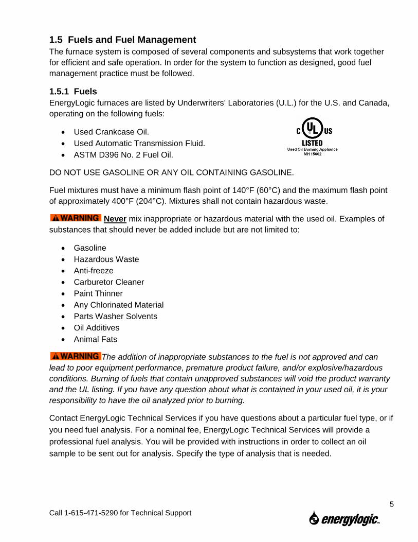
1.5.1 Fuels EnergyLogic furnaces are listed by Underwriters’ Laboratories (U.L.) for the U.S. and Canada, operating on the following fuels:
• Used Crankcase Oil. • Used Automatic Transmission Fluid. • ASTM D396 No. 2 Fuel Oil.
DO NOT USE GASOLINE OR ANY OIL CONTAINING GASOLINE.
Fuel mixtures must have a minimum flash point of 140°F (60°C) and the maximum flash point of approximately 400°F (204°C). Mixtures shall not contain hazardous waste.
Never mix inappropriate or hazardous material with the used oil. Examples of substances that should never be added include but are not limited to:
• Gasoline • Hazardous Waste • Anti-freeze • Carburetor Cleaner • Paint Thinner • Any Chlorinated Material • Parts Washer Solvents • Oil Additives • Animal Fats
The addition of inappropriate substances to the fuel is not approved and can lead to poor equipment performance, premature product failure, and/or explosive/hazardous conditions. Burning of fuels that contain unapproved substances will void the product warranty and the UL listing. If you have any question about what is contained in your used oil, it is your responsibility to have the oil analyzed prior to burning.
Contact EnergyLogic Technical Services if you have questions about a particular fuel type, or if you need fuel analysis. For a nominal fee, EnergyLogic Technical Services will provide a professional fuel analysis. You will be provided with instructions in order to collect an oil sample to be sent out for analysis. Specify the type of analysis that is needed.
5
Call 1-615-471-5290 for Technical Support
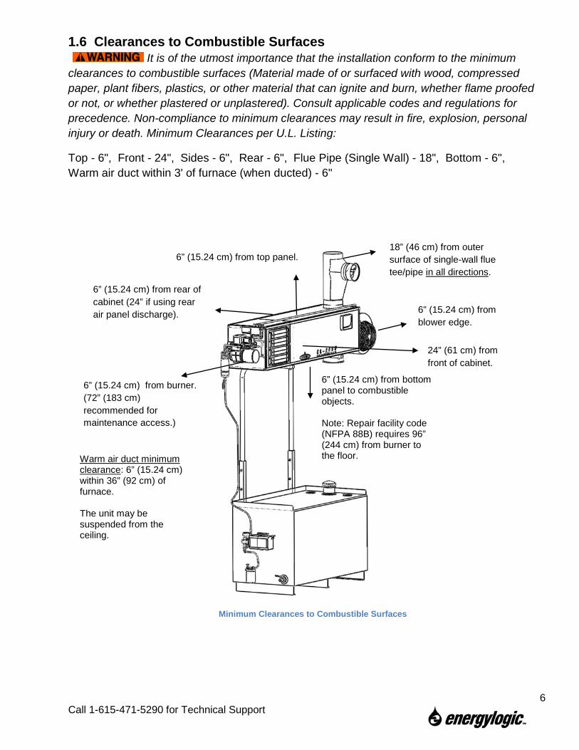
1.6 Clearances to Combustible Surfaces It is of the utmost importance that the installation conform to the minimum clearances to combustible surfaces (Material made of or surfaced with wood, compressed paper, plant fibers, plastics, or other material that can ignite and burn, whether flame proofed or not, or whether plastered or unplastered). Consult applicable codes and regulations for precedence. Non-compliance to minimum clearances may result in fire, explosion, personal injury or death. Minimum Clearances per U.L. Listing:
Top - 6", Front - 24", Sides - 6", Rear - 6", Flue Pipe (Single Wall) - 18", Bottom - 6", Warm air duct within 3' of furnace (when ducted) - 6"
18” (46 cm) from outer surface of single-wall flue tee/pipe in all directions.
6” (15.24 cm) from blower edge.
24” (61 cm) from front of cabinet.
6” (15.24 cm) from rear of cabinet (24” if using rear air panel discharge).
6” (15.24 cm) from burner. (72” (183 cm) recommended for maintenance access.)
Warm air duct minimum clearance: 6” (15.24 cm) within 36” (92 cm) of furnace. The unit may be suspended from the ceiling.
Minimum Clearances to Combustible Surfaces
6” (15.24 cm) from bottom panel to combustible objects. Note: Repair facility code (NFPA 88B) requires 96” (244 cm) from burner to the floor.
6” (15.24 cm) from top panel.
6
Call 1-615-471-5290 for Technical Support
2. Installation Considerations EnergyLogic furnaces are designed to operate reliably over a wide range of conditions. However, it is important to read this section before installation to prevent unnecessary work or problems.
2.1 Technical Guidelines 1. All components of your furnace are factory-tested to ensure proper operation. Do not
tamper with controls. 2. Pre-assembled fittings are sealed with thread-locker sealant and do not require
additional tightening. 3. Always supply power through a dedicated, hard-wired (copper only), 115VAC/60Hz
circuit with a 25 Amp maximum breaker. Check local codes. 4. Do not use the provided thread-locker sealant on flare fittings. Use the provided
sealant on all NPT threaded connections only. 5. Do not use Teflon tape on any connections. Loose strands may block small orifices,
affecting unit operation or may damage components. 6. Route all fuel lines inside building to prevent exposure to cold weather. If this is not
practical, call EnergyLogic for application support. 7. Locate furnace and tank in a dry area above 50°F (10°C) at all times. 8. If not installing the pump to an EnergyLogic Tank, mount it according to guidelines in
the EnergyLogic Top Suction Kit packaging instructions. 9. Do not kink copper tubing. Route tubing as straight and vertical as possible (no loops)
to avoid air pockets. 10. Remember to remove the blower shipping strap prior to installation. 11. Maximize vertical run of flue, and minimize horizontal run. Allow access for clean-out. 12. Mount the wall thermostat to an interior wall. Do not allow it to hang by the wiring
harness. Do not mount it to the furnace cabinet. 13. Do not allow your tank to run out of fuel. If the tank runs out of fuel, air and
contamination will be introduced into the fuel delivery system. An EnergyLogic low-level cut off switch is recommended to prevent low fuel operation.
14. Never use compression fittings for tubing connections, as they will leak and cause the burner to shut down.
15. Care should be taken not to over-tighten or cross thread brass fittings. 16. Applying a thin film of anti-seize compound to cabinet side of burner gasket may
reduce gasket sticking to cabinet when swinging burner open. 17. Another source of heat is recommended for periods when the furnace may be off-line
for maintenance or for any other reason.
7
Call 1-615-471-5290 for Technical Support
2.2 Tools Required Below is a recommended list of tools and equipment that may be used to aid in the installation of EnergyLogic furnaces. This is a minimum list for a Tank-Mount system. Additional tools and equipment are required for other mounting methods. Common Tools and Equipment
• 5/16” Combination Wrench • Flat Blade Screwdriver • 3/8” Combination Wrench • ¼” Hex Wrench or Driver
• 7/16” Combination Wrench • Wire cutter to remove tie
straps. • 1/2” Combination Wrench • Forklift or other lift device. • 9/16” Combination Wrench • Safety ladder or man lift.
• 3/4” Combination Wrench • (Tools required for flue kit
installation) • 1-3/8” Combination Wrench
2.3 Furnace Placement Guide It is important to plan the furnace and tank placement, wiring, piping and flue prior to installation.
Electrical Wiring - Will the layout of your building allow safe routing and installation of electrical wiring to the furnace? Check your local building codes. The EnergyLogic furnace requires 115 VAC/60 Hz power, supplied through a dedicated, hard wired, circuit breaker – 25 Amp maximum. Use copper conductors only. Electricity is very dangerous. Wiring must be installed by a qualified electrician. In the U.S., consult the National Electric Code (NEC) and local building codes for additional requirements. In Canada, consult the Canadian Electrical Code, Part I.
Flue Pipe - Is ceiling/roof or wall location suitable for a flue pipe to pass through? Are any obstacles or flammable materials present at interior or exterior locations? Check your roof warranty about penetration for the flue pipe. Check your local building and fire codes. Combustion and Make Up Air Requirements – It is necessary to ensure that adequate air for safe combustion is provided for oil-burning appliances and equipment. Refer to NFPA 31, chapter 5 for requirements based on the total input BTU rating of all appliances in the space. In Canada, reference CSA Standard B139/CGA B149.
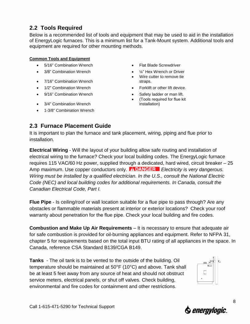
Tanks - The oil tank is to be vented to the outside of the building. Oil temperature should be maintained at 50°F (10°C) and above. Tank shall be at least 5 feet away from any source of heat and should not obstruct service meters, electrical panels, or shut off valves. Check building, environmental and fire codes for containment and other restrictions.
8
Call 1-615-471-5290 for Technical Support
Minimum Clearance – Safe clearances to combustibles (Section 1.6) shall be adhered to. Distance from Flammable Liquids – Do not create a fire or explosion hazard by using or placing flammable liquids such as gasoline or solvents near the furnace. A flammable liquid is any liquid that has a closed-cup flash point below 100°F (37.8°C), as determined by the test procedures and apparatus set forth in 1.7.4 of NFPA 30.
Access - Position the used oil storage tank to provide adequate access to filling ports, filter, drain valve and pump. Leave an unobstructed path for shop vehicles and equipment. Consider access needed for service (heat exchanger cleaning, flue cleaning, removal of drip cap and baffle, burner access, etc.). If desired, the furnace can be wall mounted or hung from the ceiling at some distance from the oil tank.
Cabinet Orientation vs. Air Flow Direction – Consider the workspace to be heated. Consider proximity to windows, doors, etc. The EnergyLogic used oil furnace is designed such that the louver and cabinet panels may be swapped and the cabinet can be rotated 180º. Consider whether or not this would be advantageous for your application. Contact EnergyLogic if louvers are needed on both sides.
Structural requirements (Canada) – In Canada, the structure in which the used oil burning appliance is housed shall be no less than 4.6m (15ft) high at the point where the appliance is situated and have a minimum length and width of 6m (20ft) and a minimum floor area of 37m2 (400ft2). In addition, the installation including flue stack height requirements and distance from property line shall be in accordance with the authorities having jurisdiction concerning environmental quality as well as fuel, fire, and electrical safety and Table 7 in CSA B140.0-03 (clause 22.3.2).
9
Call 1-615-471-5290 for Technical Support
3. Assembly and Installation – Cabinet, Tank, Pump and Suction Fuel Line. This section instructs installing the cabinet and the fuel metering pump.
3.1 Unpacking and Inspection After unpacking your new furnace, make sure you have received the proper parts and quantities shown in the checklist on the following page. For missing parts, contact EnergyLogic. If any parts were damaged during shipment, please contact your shipping carrier.
3.2 Warranty Registration IMPORTANT: You must register your furnace with EnergyLogic for the warranty to become active and to receive technical service. Please take a few minutes to fill out the Warranty Registration Card. Note: Your Warranty Registration Card may be found in the accessory box where you located this manual. You may fax the completed card to (615) 251-0682, or mail it. You may also register online at www.energylogic.com
10
Call 1-615-471-5290 for Technical Support
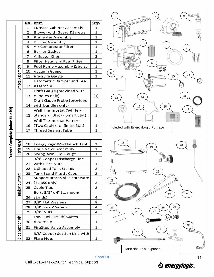
No. Item Qty.1 Furnace Cabinet Assembly 12 Blower with Guard &Screws 13 Preheater Assembly 14 Burner Assembly 15 Air Compressor Filter 16 Burner Gasket 17 Alligator Clips 28 Filter Head and Fuel Filter 19 Fuel Pump Assembly & bolts 110 Vacuum Gauge 111 Pressure Gauge 1
12Barometric Damper and Tee Assembly 1
13Draft Gauge (provided with bundles only) (1)
14Draft Gauge Probe (provided with bundles only) (1)
15Wall Thermostat (White - Standard, Black - Smart Stat) 1
16Wall Thermostat Harness (Two Cables for Smart Stat) 1
17 Thread Sealant Tube 1
18 EnergyLogic Workbench Tank 119 Drain Valve Assembly 120 Swing-Arm Fuel Gauge 1
213/8" Copper Discharge Line with Flare Nuts 1
22 L-Shaped Tank Stands 223 Tank Stand Plastic Caps 2
24Support Braces plus hardware (EL-350 only) 2
25 Cable Ties 2
26Bolts 3/8" x 4" (to mount stands) 4
27 3/8" Flat Washers 828 3/8" Lock Washers 429 3/8" Nuts 4
30Low Fuel Cut Off Switch Assembly 1
31 FireStop Valve Assembly 1
323/8" Copper Suction Line with Flare Nuts 1
Furn
ace A
ssem
bly
Furn
ace C
ompl
ete (
min
us fl
ue ki
t)
Side S
uctio
n Kit
Tank
Ass
yTa
nk M
ount
Kit
1 2 3
4 5
6 7
8 9 10 11
12
13
14
15 17
Included with EnergyLogic Furnace
16
9a
18 19 20
21
22
23
25 26 27
28 29
32
30
Tank and Tank Options
24
31
Checklist
11 Call 1-615-471-5290 for Technical Support
3.3 Furnace Cabinet Installation – On an EL Tank Follow the directions in this section if you intend to mount the furnace to stands directly above the fuel tank. If you are mounting the furnace to a structural ceiling or wall proceed to Section 3.4. Do not mount an EL-350H furnace to any EnergyLogic Tank smaller than 250 gallons.
3.3.1 Locate the EnergyLogic Used Oil Storage Tank EnergyLogic supplied workbench tanks are U.L. listed and pressure tested at the factory. However, new tanks must be leak tested by qualified installers prior to installation and use (refer to local codes and regulations). The tank must be located inside. If you are mounting the furnace to the tank, make sure that the tank is located beneath the desired location of the furnace. The tank must be on level flooring that will adequately support the full weight when loaded. Use a pallet jack or fork lift (on the bottom side of tank) to move the empty tank. Do not push or drag the tank. Maintain clearance from the tank to any source of heat (refer to local codes and regulations).
The furnace cabinet is heavy and will need to be lifted to a height of 8 feet above the floor. Use appropriate lifting and safety equipment.
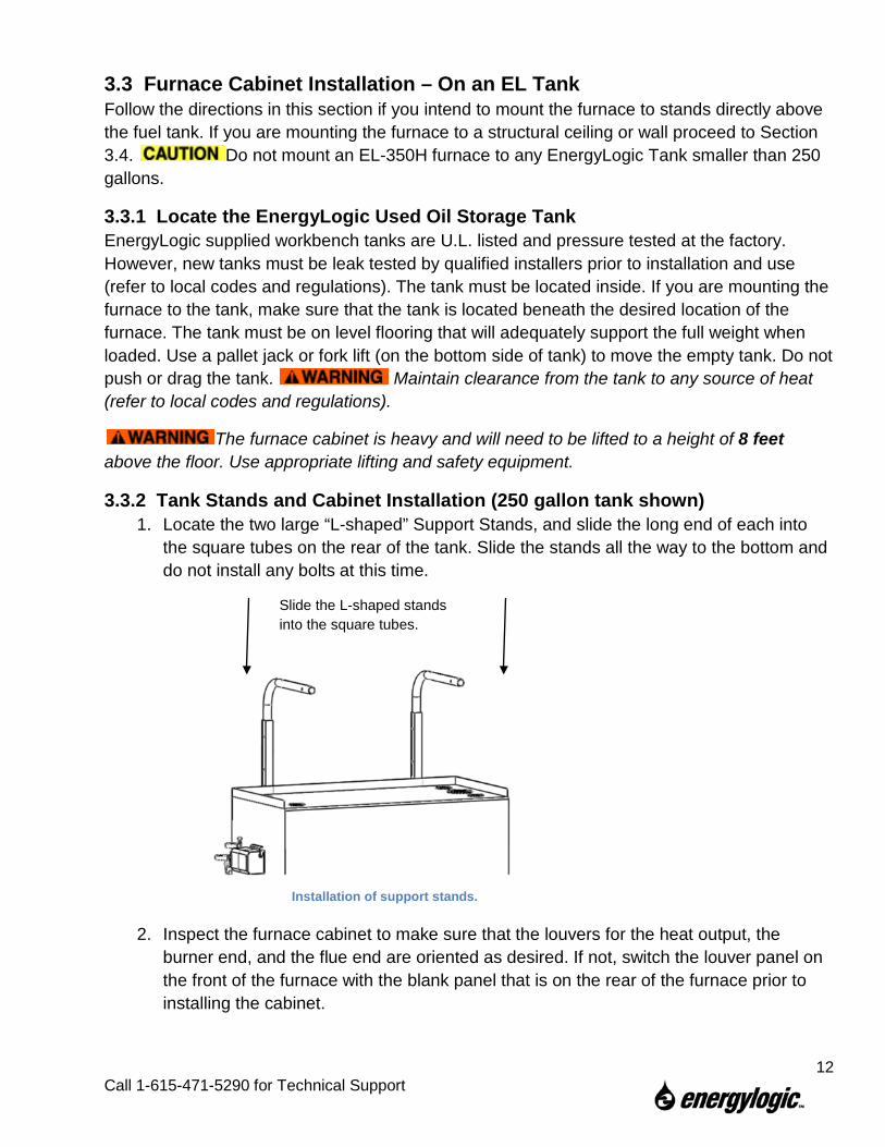
3.3.2 Tank Stands and Cabinet Installation (250 gallon tank shown) 1. Locate the two large “L-shaped” Support Stands, and slide the long end of each into
the square tubes on the rear of the tank. Slide the stands all the way to the bottom and do not install any bolts at this time.
2. Inspect the furnace cabinet to make sure that the louvers for the heat output, the
burner end, and the flue end are oriented as desired. If not, switch the louver panel on the front of the furnace with the blank panel that is on the rear of the furnace prior to installing the cabinet.
Installation of support stands.
Slide the L-shaped stands into the square tubes.
12
Call 1-615-471-5290 for Technical Support
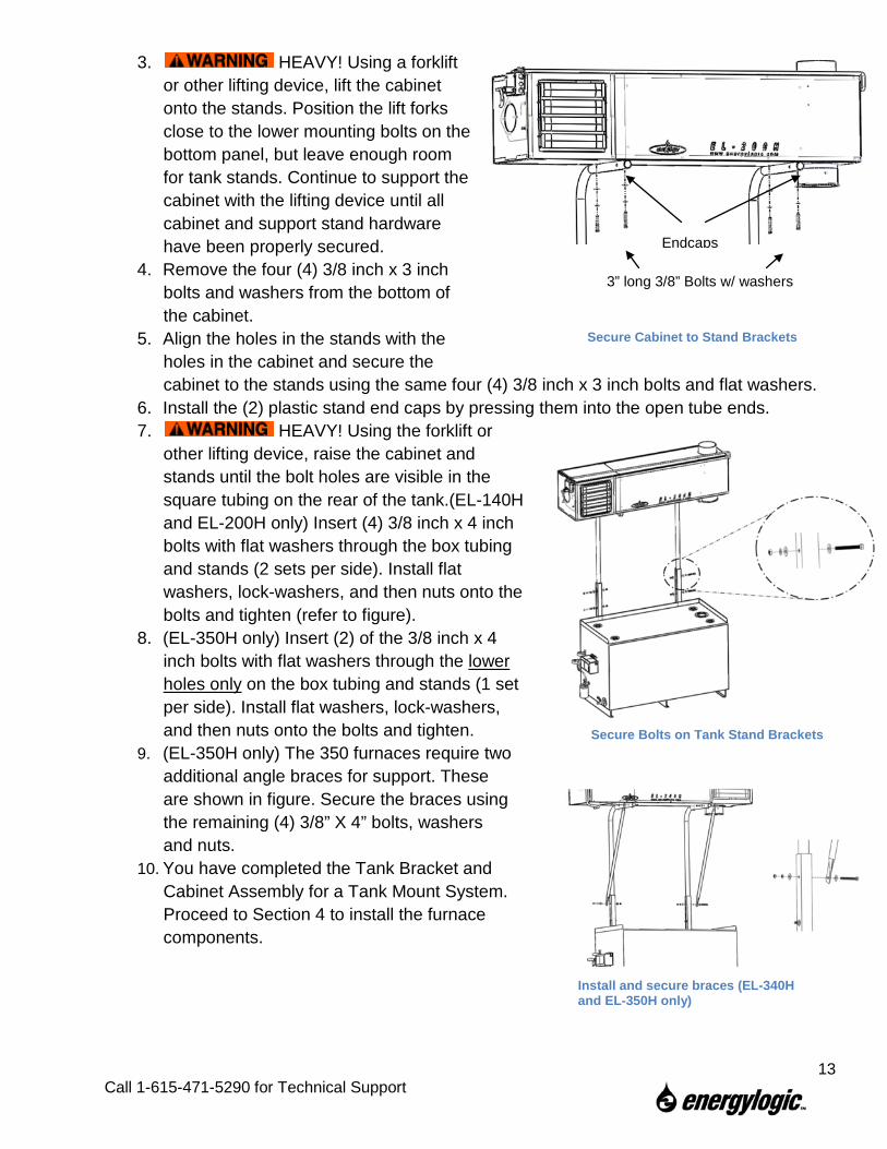
3. HEAVY! Using a forklift or other lifting device, lift the cabinet onto the stands. Position the lift forks close to the lower mounting bolts on the bottom panel, but leave enough room for tank stands. Continue to support the cabinet with the lifting device until all cabinet and support stand hardware have been properly secured.
4. Remove the four (4) 3/8 inch x 3 inch bolts and washers from the bottom of the cabinet.
5. Align the holes in the stands with the holes in the cabinet and secure the cabinet to the stands using the same four (4) 3/8 inch x 3 inch bolts and flat washers.
6. Install the (2) plastic stand end caps by pressing them into the open tube ends. 7. HEAVY! Using the forklift or
other lifting device, raise the cabinet and stands until the bolt holes are visible in the square tubing on the rear of the tank.(EL-140H and EL-200H only) Insert (4) 3/8 inch x 4 inch bolts with flat washers through the box tubing and stands (2 sets per side). Install flat washers, lock-washers, and then nuts onto the bolts and tighten (refer to figure).
8. (EL-350H only) Insert (2) of the 3/8 inch x 4 inch bolts with flat washers through the lower holes only on the box tubing and stands (1 set per side). Install flat washers, lock-washers, and then nuts onto the bolts and tighten.
9. (EL-350H only) The 350 furnaces require two additional angle braces for support. These are shown in figure. Secure the braces using the remaining (4) 3/8” X 4” bolts, washers and nuts.
10. You have completed the Tank Bracket and Cabinet Assembly for a Tank Mount System. Proceed to Section 4 to install the furnace components.
3” long 3/8” Bolts w/ washers
Endcaps
Secure Cabinet to Stand Brackets
Secure Bolts on Tank Stand Brackets
Install and secure braces (EL-340H and EL-350H only)
13
Call 1-615-471-5290 for Technical Support
3.4 Furnace Cabinet Installation – Not Mounted on a Tank
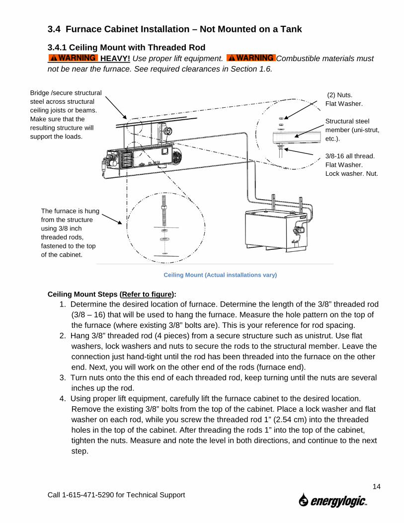
3.4.1 Ceiling Mount with Threaded Rod HEAVY! Use proper lift equipment. Combustible materials must
not be near the furnace. See required clearances in Section 1.6.
Ceiling Mount Steps (Refer to figure): 1. Determine the desired location of furnace. Determine the length of the 3/8” threaded rod
(3/8 – 16) that will be used to hang the furnace. Measure the hole pattern on the top of the furnace (where existing 3/8” bolts are). This is your reference for rod spacing.
2. Hang 3/8” threaded rod (4 pieces) from a secure structure such as unistrut. Use flat washers, lock washers and nuts to secure the rods to the structural member. Leave the connection just hand-tight until the rod has been threaded into the furnace on the other end. Next, you will work on the other end of the rods (furnace end).
3. Turn nuts onto the this end of each threaded rod, keep turning until the nuts are several inches up the rod.
4. Using proper lift equipment, carefully lift the furnace cabinet to the desired location. Remove the existing 3/8” bolts from the top of the cabinet. Place a lock washer and flat washer on each rod, while you screw the threaded rod 1” (2.54 cm) into the threaded holes in the top of the cabinet. After threading the rods 1” into the top of the cabinet, tighten the nuts. Measure and note the level in both directions, and continue to the next step.
Bridge /secure structural steel across structural ceiling joists or beams. Make sure that the resulting structure will support the loads.
The furnace is hung from the structure using 3/8 inch threaded rods, fastened to the top of the cabinet.
(2) Nuts. Flat Washer. Structural steel member (uni-strut, etc.). 3/8-16 all thread. Flat Washer. Lock washer. Nut.
Ceiling Mount (Actual installations vary)
14
Call 1-615-471-5290 for Technical Support
5. After all (4) rods have been secured into the top of the cabinet, return to the top of the rods at the ceiling support structure. Noting your level readings, adjust the furnace level using the top nuts to raise or lower each rod. Re-confirm that the furnace is level. Then, tighten the nuts to the structural steel members. Use jam nuts on top.
6. Check all fastened joints to assure that the structure and the hardware are secure. 7. An alternate method: Instead of hanging the furnace from the top fasteners, a
supporting structure may be built beneath the furnace using structural steel (unistrut, angle iron). This structure may be hung from structural ceiling supports.
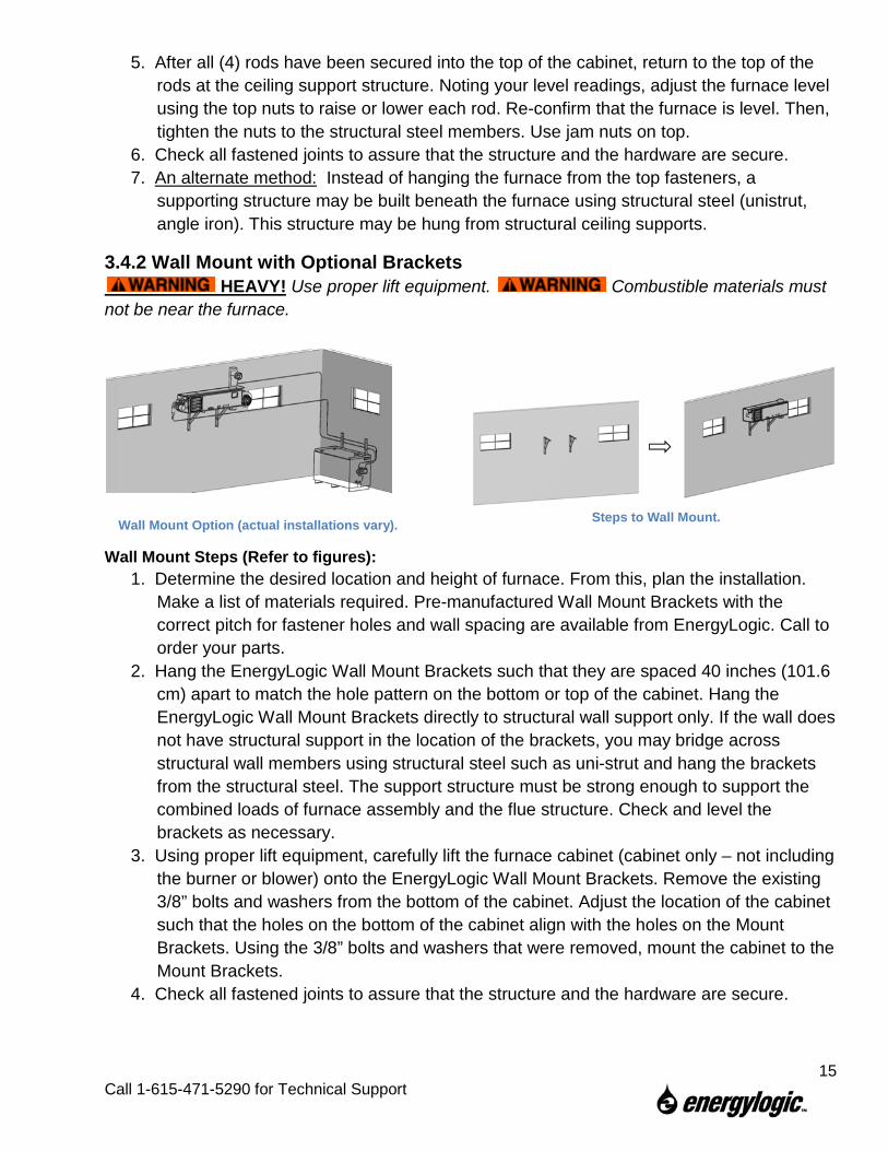
3.4.2 Wall Mount with Optional Brackets HEAVY! Use proper lift equipment. Combustible materials must
not be near the furnace.
Wall Mount Steps (Refer to figures): 1. Determine the desired location and height of furnace. From this, plan the installation.
Make a list of materials required. Pre-manufactured Wall Mount Brackets with the correct pitch for fastener holes and wall spacing are available from EnergyLogic. Call to order your parts.
2. Hang the EnergyLogic Wall Mount Brackets such that they are spaced 40 inches (101.6 cm) apart to match the hole pattern on the bottom or top of the cabinet. Hang the EnergyLogic Wall Mount Brackets directly to structural wall support only. If the wall does not have structural support in the location of the brackets, you may bridge across structural wall members using structural steel such as uni-strut and hang the brackets from the structural steel. The support structure must be strong enough to support the combined loads of furnace assembly and the flue structure. Check and level the brackets as necessary.
3. Using proper lift equipment, carefully lift the furnace cabinet (cabinet only – not including the burner or blower) onto the EnergyLogic Wall Mount Brackets. Remove the existing 3/8” bolts and washers from the bottom of the cabinet. Adjust the location of the cabinet such that the holes on the bottom of the cabinet align with the holes on the Mount Brackets. Using the 3/8” bolts and washers that were removed, mount the cabinet to the Mount Brackets.
4. Check all fastened joints to assure that the structure and the hardware are secure.
Wall Mount Option (actual installations vary). Steps to Wall Mount.
15
Call 1-615-471-5290 for Technical Support
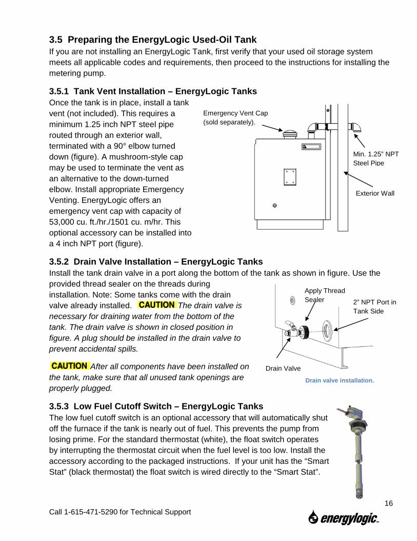
3.5 Preparing the EnergyLogic Used-Oil Tank If you are not installing an EnergyLogic Tank, first verify that your used oil storage system meets all applicable codes and requirements, then proceed to the instructions for installing the metering pump. 3.5.1 Tank Vent Installation – EnergyLogic Tanks Once the tank is in place, install a tank vent (not included). This requires a minimum 1.25 inch NPT steel pipe routed through an exterior wall, terminated with a 90° elbow turned down (figure). A mushroom-style cap may be used to terminate the vent as an alternative to the down-turned elbow. Install appropriate Emergency Venting. EnergyLogic offers an emergency vent cap with capacity of 53,000 cu. ft./hr./1501 cu. m/hr. This optional accessory can be installed into a 4 inch NPT port (figure).
3.5.2 Drain Valve Installation – EnergyLogic Tanks Install the tank drain valve in a port along the bottom of the tank as shown in figure. Use the provided thread sealer on the threads during installation. Note: Some tanks come with the drain valve already installed. The drain valve is necessary for draining water from the bottom of the tank. The drain valve is shown in closed position in figure. A plug should be installed in the drain valve to prevent accidental spills.
After all components have been installed on the tank, make sure that all unused tank openings are properly plugged.
3.5.3 Low Fuel Cutoff Switch – EnergyLogic Tanks The low fuel cutoff switch is an optional accessory that will automatically shut off the furnace if the tank is nearly out of fuel. This prevents the pump from losing prime. For the standard thermostat (white), the float switch operates by interrupting the thermostat circuit when the fuel level is too low. Install the accessory according to the packaged instructions. If your unit has the “Smart Stat” (black thermostat) the float switch is wired directly to the “Smart Stat”.
Exterior Wall
Emergency Vent Cap (sold separately).
Min. 1.25” NPT Steel Pipe
Drain Valve
2” NPT Port in Tank Side
Apply Thread Sealer
Drain valve installation.
16
Call 1-615-471-5290 for Technical Support
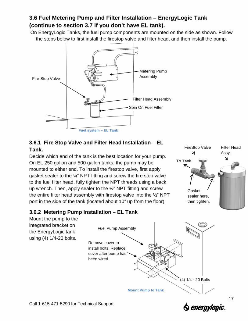
3.6 Fuel Metering Pump and Filter Installation – EnergyLogic Tank (continue to section 3.7 if you don’t have EL tank). On EnergyLogic Tanks, the fuel pump components are mounted on the side as shown. Follow
the steps below to first install the firestop valve and filter head, and then install the pump.
3.6.1 Fire Stop Valve and Filter Head Installation – EL Tank. Decide which end of the tank is the best location for your pump. On EL 250 gallon and 500 gallon tanks, the pump may be mounted to either end. To install the firestop valve, first apply gasket sealer to the ¼” NPT fitting and screw the fire stop valve to the fuel filter head, fully tighten the NPT threads using a back up wrench. Then, apply sealer to the ½” NPT fitting and screw the entire filter head assembly with firestop valve into the ½” NPT port in the side of the tank (located about 10” up from the floor).
3.6.2 Metering Pump Installation – EL Tank Mount the pump to the integrated bracket on the EnergyLogic tank using (4) 1/4-20 bolts.
Fire-Stop Valve
Filter Head Assembly
Spin On Fuel Filter
Metering Pump Assembly
Fuel system – EL Tank
Gasket sealer here, then tighten.
FireStop Valve Filter Head Assy.
To Tank
(4) 1/4 - 20 Bolts
Remove cover to install bolts. Replace cover after pump has been wired.
Fuel Pump Assembly
Mount Pump to Tank
17 Call 1-615-471-5290 for Technical Support
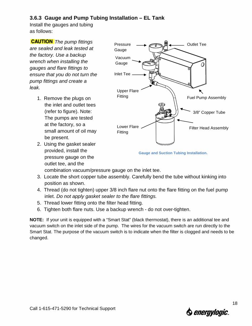
3.6.3 Gauge and Pump Tubing Installation – EL Tank Install the gauges and tubing as follows:
The pump fittings are sealed and leak tested at the factory. Use a backup wrench when installing the gauges and flare fittings to ensure that you do not turn the pump fittings and create a leak.
1. Remove the plugs on the inlet and outlet tees (refer to figure). Note: The pumps are tested at the factory, so a small amount of oil may be present.
2. Using the gasket sealer provided, install the pressure gauge on the outlet tee, and the combination vacuum/pressure gauge on the inlet tee.
3. Locate the short copper tube assembly. Carefully bend the tube without kinking into position as shown.
4. Thread (do not tighten) upper 3/8 inch flare nut onto the flare fitting on the fuel pump inlet. Do not apply gasket sealer to the flare fittings.
5. Thread lower fitting onto the filter head fitting. 6. Tighten both flare nuts. Use a backup wrench - do not over-tighten.
NOTE: If your unit is equipped with a “Smart Stat” (black thermostat), there is an additional tee and vacuum switch on the inlet side of the pump. The wires for the vacuum switch are run directly to the Smart Stat. The purpose of the vacuum switch is to indicate when the filter is clogged and needs to be changed.
Fuel Pump Assembly
Filter Head Assembly
3/8” Copper Tube
Inlet Tee
Vacuum Gauge
Pressure Gauge
Outlet Tee
Upper Flare Fitting
Lower Flare Fitting
Gauge and Suction Tubing Installation.
18
Call 1-615-471-5290 for Technical Support
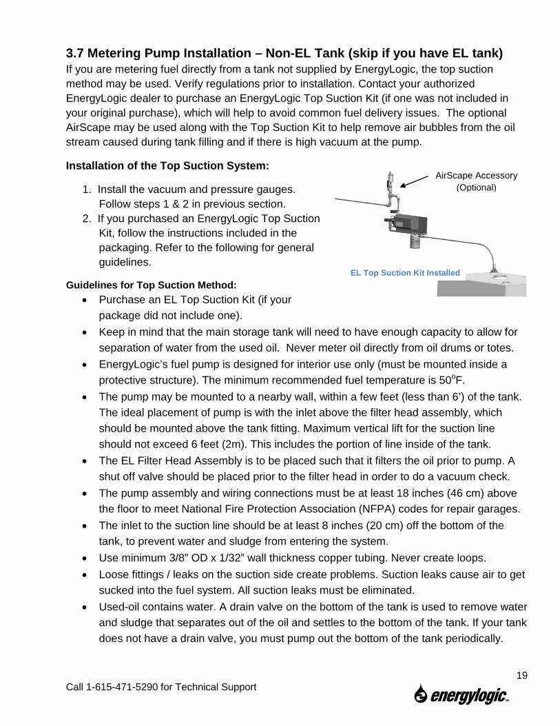
3.7 Metering Pump Installation – Non-EL Tank (skip if you have EL tank) If you are metering fuel directly from a tank not supplied by EnergyLogic, the top suction method may be used. Verify regulations prior to installation. Contact your authorized EnergyLogic dealer to purchase an EnergyLogic Top Suction Kit (if one was not included in your original purchase), which will help to avoid common fuel delivery issues. The optional AirScape may be used along with the Top Suction Kit to help remove air bubbles from the oil stream caused during tank filling and if there is high vacuum at the pump.
Installation of the Top Suction System:
1. Install the vacuum and pressure gauges. Follow steps 1 & 2 in previous section.
2. If you purchased an EnergyLogic Top Suction Kit, follow the instructions included in the packaging. Refer to the following for general guidelines.
Guidelines for Top Suction Method: • Purchase an EL Top Suction Kit (if your
package did not include one). • Keep in mind that the main storage tank will need to have enough capacity to allow for
separation of water from the used oil. Never meter oil directly from oil drums or totes. • EnergyLogic’s fuel pump is designed for interior use only (must be mounted inside a
protective structure). The minimum recommended fuel temperature is 50oF. • The pump may be mounted to a nearby wall, within a few feet (less than 6’) of the tank.
The ideal placement of pump is with the inlet above the filter head assembly, which should be mounted above the tank fitting. Maximum vertical lift for the suction line should not exceed 6 feet (2m). This includes the portion of line inside of the tank.
• The EL Filter Head Assembly is to be placed such that it filters the oil prior to pump. A shut off valve should be placed prior to the filter head in order to do a vacuum check.
• The pump assembly and wiring connections must be at least 18 inches (46 cm) above the floor to meet National Fire Protection Association (NFPA) codes for repair garages.
• The inlet to the suction line should be at least 8 inches (20 cm) off the bottom of the tank, to prevent water and sludge from entering the system.
• Use minimum 3/8” OD x 1/32” wall thickness copper tubing. Never create loops. • Loose fittings / leaks on the suction side create problems. Suction leaks cause air to get
sucked into the fuel system. All suction leaks must be eliminated. • Used-oil contains water. A drain valve on the bottom of the tank is used to remove water
and sludge that separates out of the oil and settles to the bottom of the tank. If your tank does not have a drain valve, you must pump out the bottom of the tank periodically.
EL Top Suction Kit Installed
AirScape Accessory (Optional)
19
Call 1-615-471-5290 for Technical Support
4. Installation of Furnace Components With the cabinet in place, you are ready to attach the blower assembly, the burner assembly, and the preheater. Then, you will install the fuel tubing from the pump to the preheater.
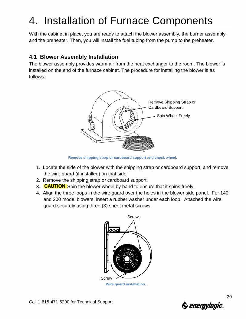
4.1 Blower Assembly Installation The blower assembly provides warm air from the heat exchanger to the room. The blower is installed on the end of the furnace cabinet. The procedure for installing the blower is as follows:
1. Locate the side of the blower with the shipping strap or cardboard support, and remove the wire guard (if installed) on that side.
2. Remove the shipping strap or cardboard support. 3. Spin the blower wheel by hand to ensure that it spins freely. 4. Align the three loops in the wire guard over the holes in the blower side panel. For 140
and 200 model blowers, insert a rubber washer under each loop. Attached the wire guard securely using three (3) sheet metal screws.
Screw
Screws
Wire guard installation.
Remove shipping strap or cardboard support and check wheel.
Remove Shipping Strap or Cardboard Support
Spin Wheel Freely
20
Call 1-615-471-5290 for Technical Support
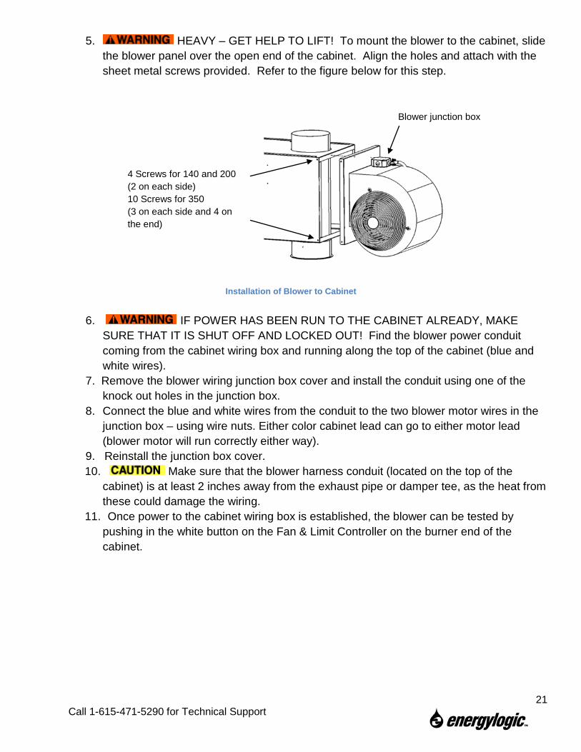
5. HEAVY – GET HELP TO LIFT! To mount the blower to the cabinet, slide the blower panel over the open end of the cabinet. Align the holes and attach with the sheet metal screws provided. Refer to the figure below for this step.
6. IF POWER HAS BEEN RUN TO THE CABINET ALREADY, MAKE SURE THAT IT IS SHUT OFF AND LOCKED OUT! Find the blower power conduit coming from the cabinet wiring box and running along the top of the cabinet (blue and white wires).
7. Remove the blower wiring junction box cover and install the conduit using one of the knock out holes in the junction box.
8. Connect the blue and white wires from the conduit to the two blower motor wires in the junction box – using wire nuts. Either color cabinet lead can go to either motor lead (blower motor will run correctly either way).
9. Reinstall the junction box cover. 10. Make sure that the blower harness conduit (located on the top of the
cabinet) is at least 2 inches away from the exhaust pipe or damper tee, as the heat from these could damage the wiring.
11. Once power to the cabinet wiring box is established, the blower can be tested by pushing in the white button on the Fan & Limit Controller on the burner end of the cabinet.
4 Screws for 140 and 200 (2 on each side) 10 Screws for 350 (3 on each side and 4 on the end)
Blower junction box
Installation of Blower to Cabinet
21
Call 1-615-471-5290 for Technical Support
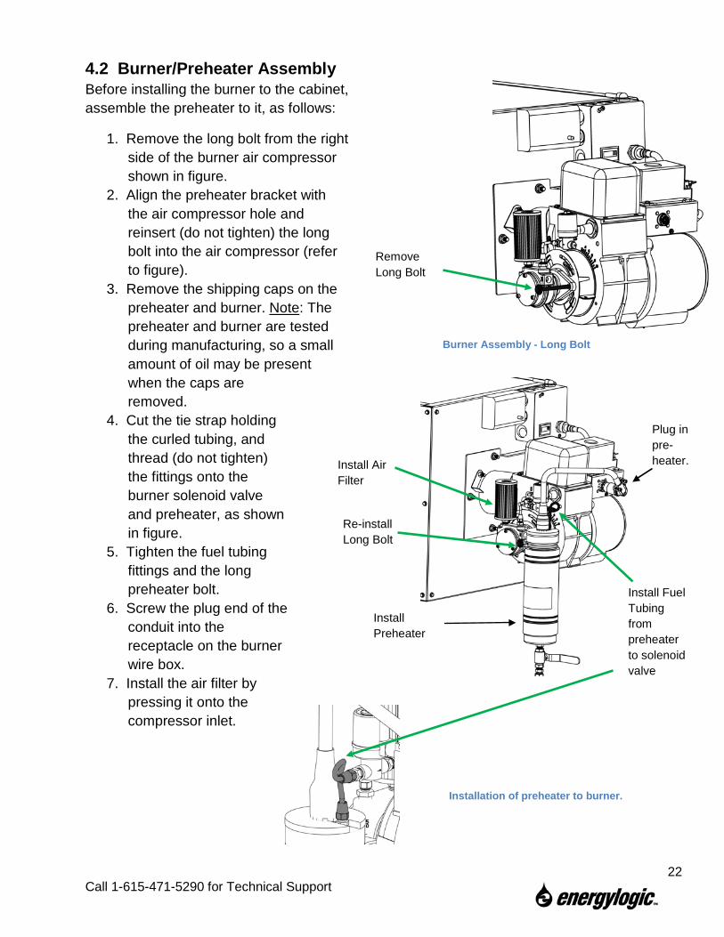
Installation of preheater to burner.
4.2 Burner/Preheater Assembly Before installing the burner to the cabinet, assemble the preheater to it, as follows:
1. Remove the long bolt from the right side of the burner air compressor shown in figure.
2. Align the preheater bracket with the air compressor hole and reinsert (do not tighten) the long bolt into the air compressor (refer to figure).
3. Remove the shipping caps on the preheater and burner. Note: The preheater and burner are tested during manufacturing, so a small amount of oil may be present when the caps are removed.
4. Cut the tie strap holding the curled tubing, and thread (do not tighten) the fittings onto the burner solenoid valve and preheater, as shown in figure.
5. Tighten the fuel tubing fittings and the long preheater bolt.
6. Screw the plug end of the conduit into the receptacle on the burner wire box.
7. Install the air filter by pressing it onto the compressor inlet.
Remove Long Bolt
Burner Assembly - Long Bolt
Re-install Long Bolt
Install Preheater
Install Air Filter
Install Fuel Tubing from preheater to solenoid valve
Plug in pre-heater.
22
Call 1-615-471-5290 for Technical Support
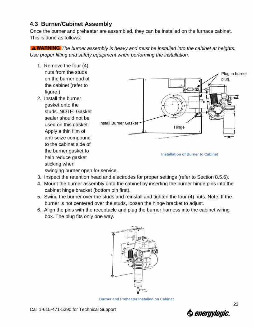
4.3 Burner/Cabinet Assembly Once the burner and preheater are assembled, they can be installed on the furnace cabinet. This is done as follows:
The burner assembly is heavy and must be installed into the cabinet at heights. Use proper lifting and safety equipment when performing the installation.
1. Remove the four (4) nuts from the studs on the burner end of the cabinet (refer to figure.)
2. Install the burner gasket onto the studs. NOTE: Gasket sealer should not be used on this gasket. Apply a thin film of anti-seize compound to the cabinet side of the burner gasket to help reduce gasket sticking when swinging burner open for service.
3. Inspect the retention head and electrodes for proper settings (refer to Section 8.5.6). 4. Mount the burner assembly onto the cabinet by inserting the burner hinge pins into the
cabinet hinge bracket (bottom pin first). 5. Swing the burner over the studs and reinstall and tighten the four (4) nuts. Note: If the
burner is not centered over the studs, loosen the hinge bracket to adjust. 6. Align the pins with the receptacle and plug the burner harness into the cabinet wiring
box. The plug fits only one way.
Installation of Burner to Cabinet
Install Burner Gasket
Plug in burner plug.
Hinge
Burner and Preheater Installed on Cabinet 23
Call 1-615-471-5290 for Technical Support
4.4 Pump Outlet Tubing Installation Now that you have installed the burner, you will install the fuel tubing between the pump and the preheater.
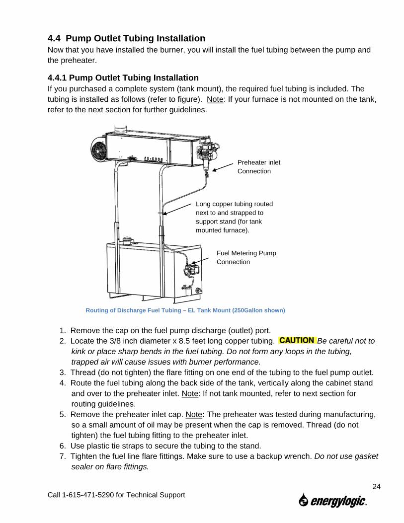
4.4.1 Pump Outlet Tubing Installation If you purchased a complete system (tank mount), the required fuel tubing is included. The tubing is installed as follows (refer to figure). Note: If your furnace is not mounted on the tank, refer to the next section for further guidelines.
1. Remove the cap on the fuel pump discharge (outlet) port. 2. Locate the 3/8 inch diameter x 8.5 feet long copper tubing. Be careful not to
kink or place sharp bends in the fuel tubing. Do not form any loops in the tubing, trapped air will cause issues with burner performance.
3. Thread (do not tighten) the flare fitting on one end of the tubing to the fuel pump outlet. 4. Route the fuel tubing along the back side of the tank, vertically along the cabinet stand
and over to the preheater inlet. Note: If not tank mounted, refer to next section for routing guidelines.
5. Remove the preheater inlet cap. Note: The preheater was tested during manufacturing, so a small amount of oil may be present when the cap is removed. Thread (do not tighten) the fuel tubing fitting to the preheater inlet.
6. Use plastic tie straps to secure the tubing to the stand. 7. Tighten the fuel line flare fittings. Make sure to use a backup wrench. Do not use gasket
sealer on flare fittings.
Routing of Discharge Fuel Tubing – EL Tank Mount (250Gallon shown)
Long copper tubing routed next to and strapped to support stand (for tank mounted furnace).
Fuel Metering Pump Connection
Preheater inlet Connection
24
Call 1-615-471-5290 for Technical Support
4.4.2 Pump Outlet Tubing Installation – Ceiling or Wall Mounted Furnace (skip if you have a tank mounted furnace) If installing the furnace with a remote tank, the required fuel discharge tubing is not included. The tubing is installed with the same procedure as in Section 4.4.1, except for tube routing. The following guidelines are provided:
Pump Discharge Tubing Considerations: • Use 3/8” O.D. copper tubing, with 1/32” wall thickness. • The discharge line must have an upward slope towards the preheater, with no loops or
high points to trap air. Run it as straight as possible. • If high points are unavoidable, install high-point-bleed kits (available accessory)
wherever the discharge line routing steps down to provide a means to bleed trapped air in the line during priming.
• Use 45° flare connections for copper tube. Never use compression fittings. • Maximum vertical run of discharge tubing is 30 feet. • Maximum total run of discharge tubing is 150 feet. • Discharge line from the metering pump must be run indoors, with a minimum ambient
temperature of 50°F (10°C). • Installation of a shut-off valve after the fuel pump will make routine maintenance easier.
It will prevent loss of oil in the discharge line if the pump discharge connection is to be loosened for priming or other maintenance.
• The use of a remote system gauge kit (available accessory) is recommended in order to have convenient pressure readings available at the burner.
25
Call 1-615-471-5290 for Technical Support
5. Exhaust Flue System Installation The exhaust system is critical for the safe operation of the furnace, as it exhausts the products of combustion out of the building to the ambient environment.
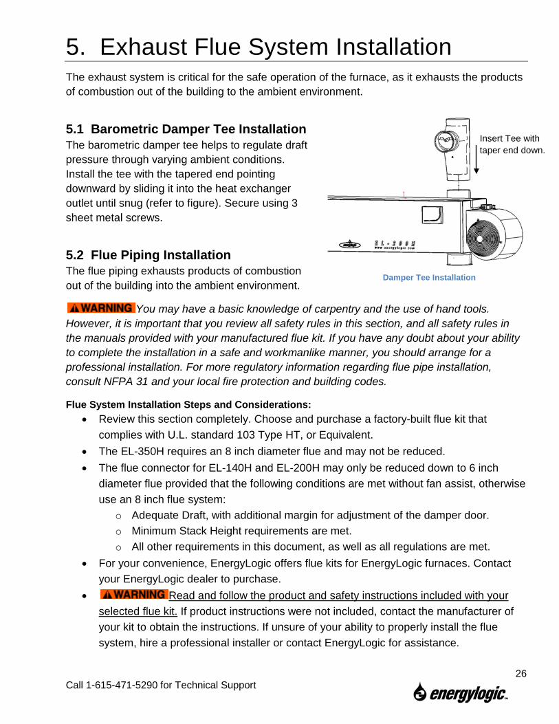
5.1 Barometric Damper Tee Installation The barometric damper tee helps to regulate draft pressure through varying ambient conditions. Install the tee with the tapered end pointing downward by sliding it into the heat exchanger outlet until snug (refer to figure). Secure using 3 sheet metal screws.
5.2 Flue Piping Installation The flue piping exhausts products of combustion out of the building into the ambient environment.
You may have a basic knowledge of carpentry and the use of hand tools. However, it is important that you review all safety rules in this section, and all safety rules in the manuals provided with your manufactured flue kit. If you have any doubt about your ability to complete the installation in a safe and workmanlike manner, you should arrange for a professional installation. For more regulatory information regarding flue pipe installation, consult NFPA 31 and your local fire protection and building codes.
Flue System Installation Steps and Considerations: • Review this section completely. Choose and purchase a factory-built flue kit that
complies with U.L. standard 103 Type HT, or Equivalent. • The EL-350H requires an 8 inch diameter flue and may not be reduced. • The flue connector for EL-140H and EL-200H may only be reduced down to 6 inch
diameter flue provided that the following conditions are met without fan assist, otherwise use an 8 inch flue system:
o Adequate Draft, with additional margin for adjustment of the damper door. o Minimum Stack Height requirements are met. o All other requirements in this document, as well as all regulations are met.
• For your convenience, EnergyLogic offers flue kits for EnergyLogic furnaces. Contact your EnergyLogic dealer to purchase.
• Read and follow the product and safety instructions included with your selected flue kit. If product instructions were not included, contact the manufacturer of your kit to obtain the instructions. If unsure of your ability to properly install the flue system, hire a professional installer or contact EnergyLogic for assistance.
Damper Tee Installation
Insert Tee with taper end down.
26
Call 1-615-471-5290 for Technical Support
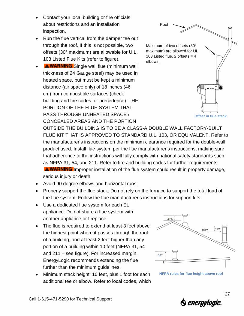
• Contact your local building or fire officials about restrictions and an installation inspection.
• Run the flue vertical from the damper tee out through the roof. If this is not possible, two offsets (30° maximum) are allowable for U.L. 103 Listed Flue Kits (refer to figure).
• Single wall flue (minimum wall thickness of 24 Gauge steel) may be used in heated space, but must be kept a minimum distance (air space only) of 18 inches (46 cm) from combustible surfaces (check building and fire codes for precedence). THE PORTION OF THE FLUE SYSTEM THAT PASS THROUGH UNHEATED SPACE / CONCEALED AREAS AND THE PORTION OUTSIDE THE BUILDING IS TO BE A CLASS-A DOUBLE WALL FACTORY-BUILT FLUE KIT THAT IS APPROVED TO STANDARD U.L. 103, OR EQUIVALENT. Refer to the manufacturer’s instructions on the minimum clearance required for the double-wall product used. Install flue system per the flue manufacturer’s instructions, making sure that adherence to the instructions will fully comply with national safety standards such as NFPA 31, 54, and 211. Refer to fire and building codes for further requirements.
Improper installation of the flue system could result in property damage, serious injury or death.
• Avoid 90 degree elbows and horizontal runs. • Properly support the flue stack. Do not rely on the furnace to support the total load of
the flue system. Follow the flue manufacturer’s instructions for support kits. • Use a dedicated flue system for each EL
appliance. Do not share a flue system with another appliance or fireplace.
• The flue is required to extend at least 3 feet above the highest point where it passes through the roof of a building, and at least 2 feet higher than any portion of a building within 10 feet (NFPA 31, 54 and 211 – see figure). For increased margin, EnergyLogic recommends extending the flue further than the minimum guidelines.
• Minimum stack height: 10 feet, plus 1 foot for each additional tee or elbow. Refer to local codes, which
NFPA rules for flue height above roof
Maximum of two offsets (30º maximum) are allowed for UL 103 Listed flue. 2 offsets = 4 elbows.
Roof
Offset in flue stack
27
Call 1-615-471-5290 for Technical Support
may require additional stack height based on BTU input. • In Canada, installation including stack height requirements and distance from property
line shall be in accordance with the authorities having jurisdiction concerning environmental quality as well as fuel, fire, and electrical safety and Table 7 in CSA B140.0-03 (clause 22.3.2).
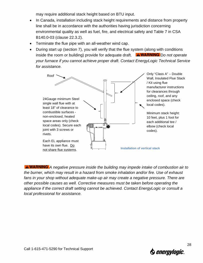
• Terminate the flue pipe with an all-weather wind cap. • During start up (section 7), you will verify that the flue system (along with conditions
inside the room or building) provide for adequate draft. Do not operate your furnace if you cannot achieve proper draft. Contact EnergyLogic Technical Service for assistance.
A negative pressure inside the building may impede intake of combustion air to the burner, which may result in a hazard from smoke inhalation and/or fire. Use of exhaust fans in your shop without adequate make-up air may create a negative pressure. There are other possible causes as well. Corrective measures must be taken before operating the appliance if the correct draft setting cannot be achieved. Contact EnergyLogic or consult a local professional for assistance.
Damper Tee Installation
Installation of vertical stack
24Gauge minimum Steel single wall flue with at least 18” of clearance to combustible surfaces -non-enclosed, heated space areas only (check local codes). Secure each joint with 3 screws or rivets.
Minimum stack height: 10 feet, plus 1 foot for each additional tee / elbow (check local codes).
Each EL appliance must have its own flue. Do not share flue systems.
Roof Only “Class A” – Double Wall, Insulated Flue Stack / Kit using flue manufacturer instructions for clearances through ceiling, roof, and any enclosed space (check local codes).
28
Call 1-615-471-5290 for Technical Support
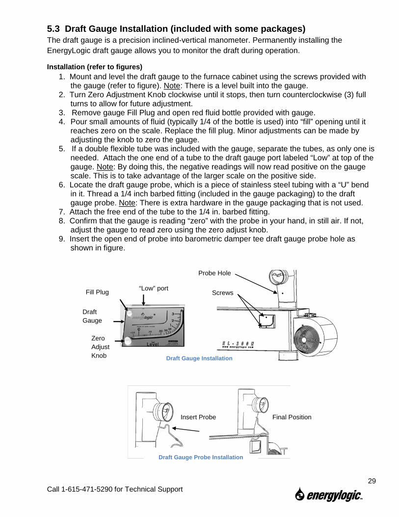
5.3 Draft Gauge Installation (included with some packages) The draft gauge is a precision inclined-vertical manometer. Permanently installing the EnergyLogic draft gauge allows you to monitor the draft during operation.
Installation (refer to figures) 1. Mount and level the draft gauge to the furnace cabinet using the screws provided with
the gauge (refer to figure). Note: There is a level built into the gauge. 2. Turn Zero Adjustment Knob clockwise until it stops, then turn counterclockwise (3) full
turns to allow for future adjustment. 3. Remove gauge Fill Plug and open red fluid bottle provided with gauge. 4. Pour small amounts of fluid (typically 1/4 of the bottle is used) into “fill” opening until it
reaches zero on the scale. Replace the fill plug. Minor adjustments can be made by adjusting the knob to zero the gauge.
5. If a double flexible tube was included with the gauge, separate the tubes, as only one is needed. Attach the one end of a tube to the draft gauge port labeled “Low” at top of the gauge. Note: By doing this, the negative readings will now read positive on the gauge scale. This is to take advantage of the larger scale on the positive side.
6. Locate the draft gauge probe, which is a piece of stainless steel tubing with a “U” bend in it. Thread a 1/4 inch barbed fitting (included in the gauge packaging) to the draft gauge probe. Note: There is extra hardware in the gauge packaging that is not used.
7. Attach the free end of the tube to the 1/4 in. barbed fitting. 8. Confirm that the gauge is reading “zero” with the probe in your hand, in still air. If not,
adjust the gauge to read zero using the zero adjust knob. 9. Insert the open end of probe into barometric damper tee draft gauge probe hole as
shown in figure.
Probe Hole
Screws “Low” port Fill Plug
Draft Gauge
Zero Adjust Knob Draft Gauge Installation
Insert Probe Final Position
Draft Gauge Probe Installation
29
Call 1-615-471-5290 for Technical Support
6. Electrical System Installation Power requirements: a dedicated, hard-wired 115VAC/60Hz circuit with a 25 Amp maximum circuit breaker. Use copper conductors only. A wiring diagram is provided in the Appendix.
Electricity is very dangerous. Wiring should be completed by a qualified electrician. Consult the National Electric Code (NEC) and local codes for additional requirements. In Canada, consult the Canadian Electrical Code, Part I.
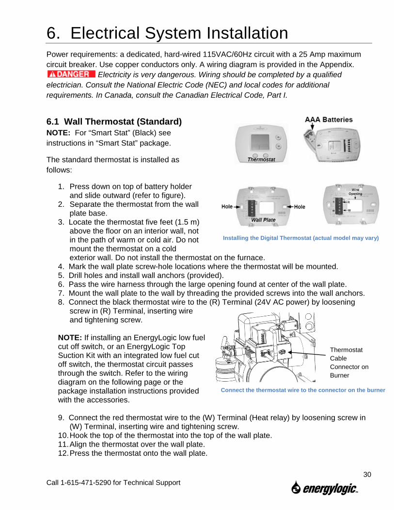
6.1 Wall Thermostat (Standard) NOTE: For “Smart Stat” (Black) see instructions in “Smart Stat” package.
The standard thermostat is installed as follows:
1. Press down on top of battery holder and slide outward (refer to figure).
2. Separate the thermostat from the wall plate base.
3. Locate the thermostat five feet (1.5 m) above the floor on an interior wall, not in the path of warm or cold air. Do not mount the thermostat on a cold exterior wall. Do not install the thermostat on the furnace.
4. Mark the wall plate screw-hole locations where the thermostat will be mounted. 5. Drill holes and install wall anchors (provided). 6. Pass the wire harness through the large opening found at center of the wall plate. 7. Mount the wall plate to the wall by threading the provided screws into the wall anchors. 8. Connect the black thermostat wire to the (R) Terminal (24V AC power) by loosening
screw in (R) Terminal, inserting wire and tightening screw.
NOTE: If installing an EnergyLogic low fuel cut off switch, or an EnergyLogic Top Suction Kit with an integrated low fuel cut off switch, the thermostat circuit passes through the switch. Refer to the wiring diagram on the following page or the package installation instructions provided with the accessories. 9. Connect the red thermostat wire to the (W) Terminal (Heat relay) by loosening screw in
(W) Terminal, inserting wire and tightening screw. 10. Hook the top of the thermostat into the top of the wall plate. 11. Align the thermostat over the wall plate. 12. Press the thermostat onto the wall plate.
Connect the thermostat wire to the connector on the burner
Thermostat Cable Connector on Burner
Installing the Digital Thermostat (actual model may vary)
30
Call 1-615-471-5290 for Technical Support
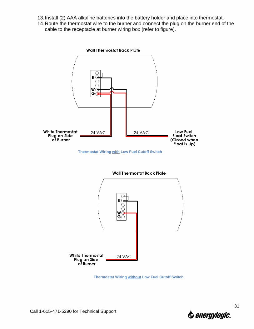
13. Install (2) AAA alkaline batteries into the battery holder and place into thermostat. 14. Route the thermostat wire to the burner and connect the plug on the burner end of the
cable to the receptacle at burner wiring box (refer to figure).
Thermostat Wiring with Low Fuel Cutoff Switch
Thermostat Wiring without Low Fuel Cutoff Switch
31
Call 1-615-471-5290 for Technical Support
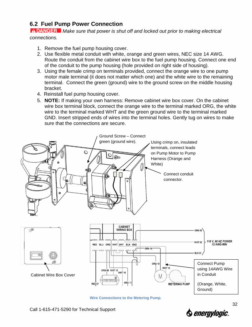
6.2 Fuel Pump Power Connection Make sure that power is shut off and locked out prior to making electrical
connections.
1. Remove the fuel pump housing cover. 2. Use flexible metal conduit with white, orange and green wires, NEC size 14 AWG.
Route the conduit from the cabinet wire box to the fuel pump housing. Connect one end of the conduit to the pump housing (hole provided on right side of housing).
3. Using the female crimp on terminals provided, connect the orange wire to one pump motor male terminal (it does not matter which one) and the white wire to the remaining terminal. Connect the green (ground) wire to the ground screw on the middle housing bracket.
4. Reinstall fuel pump housing cover. 5. NOTE: If making your own harness: Remove cabinet wire box cover. On the cabinet
wire box terminal block, connect the orange wire to the terminal marked ORG, the white wire to the terminal marked WHT and the green ground wire to the terminal marked GND. Insert stripped ends of wires into the terminal holes. Gently tug on wires to make sure that the connections are secure.
Ground Screw – Connect green (ground wire). Using crimp on, insulated
terminals, connect leads on Pump Motor to Pump Harness (Orange and White)
Connect conduit connector.
Wire Connections to the Metering Pump.
Cabinet Wire Box Cover
Connect Pump using 14AWG Wire in Conduit
(Orange, White, Ground)
32
Call 1-615-471-5290 for Technical Support
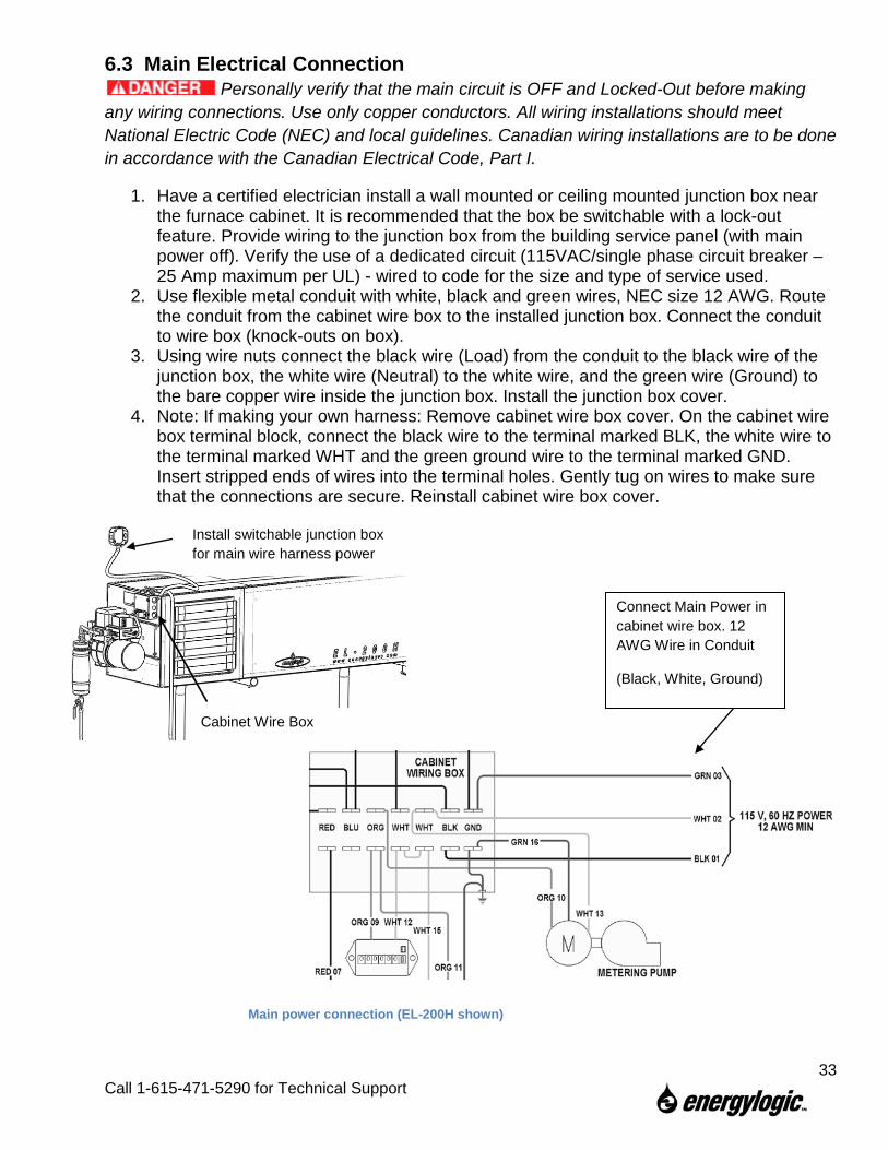
6.3 Main Electrical Connection Personally verify that the main circuit is OFF and Locked-Out before making
any wiring connections. Use only copper conductors. All wiring installations should meet National Electric Code (NEC) and local guidelines. Canadian wiring installations are to be done in accordance with the Canadian Electrical Code, Part I.
1. Have a certified electrician install a wall mounted or ceiling mounted junction box near the furnace cabinet. It is recommended that the box be switchable with a lock-out feature. Provide wiring to the junction box from the building service panel (with main power off). Verify the use of a dedicated circuit (115VAC/single phase circuit breaker – 25 Amp maximum per UL) - wired to code for the size and type of service used.
2. Use flexible metal conduit with white, black and green wires, NEC size 12 AWG. Route the conduit from the cabinet wire box to the installed junction box. Connect the conduit to wire box (knock-outs on box).
3. Using wire nuts connect the black wire (Load) from the conduit to the black wire of the junction box, the white wire (Neutral) to the white wire, and the green wire (Ground) to the bare copper wire inside the junction box. Install the junction box cover.
4. Note: If making your own harness: Remove cabinet wire box cover. On the cabinet wire box terminal block, connect the black wire to the terminal marked BLK, the white wire to the terminal marked WHT and the green ground wire to the terminal marked GND. Insert stripped ends of wires into the terminal holes. Gently tug on wires to make sure that the connections are secure. Reinstall cabinet wire box cover.
Install switchable junction box for main wire harness power
Main power connection (EL-200H shown)
Cabinet Wire Box
Connect Main Power in cabinet wire box. 12 AWG Wire in Conduit
(Black, White, Ground)
33
Call 1-615-471-5290 for Technical Support
7. Startup and Operation Once setup properly, EnergyLogic furnaces are designed to operate reliably over a wide range of conditions with minimal adjustment. This section is provided to make sure that the furnace is set up properly, and to provide instructions on the initial start up.
7.1 Do’s and Don’ts/Tech Tips 1. Read each procedure completely before performing the steps. 2. Do not burn gasoline or kerosene in your furnace. 3. Do not place chlorinated solvents into the tank. 4. Do not burn antifreeze coolant (ethylene glycol) in your furnace. 5. Regularly check for water and/or coolant in the tank at the tank drain. 6. Do not allow your fuel tank to run out of fuel (avoid the hassles of small particle
contamination and re-priming of the fuel system). 7. Document the pressure and vacuum readings of the furnace after it has been operated
several hours. This will assist with future diagnostics, if necessary. 8. Do not place fuel suspected of having debris, such as an oil dry product, into the tank. 9. Store this manual in an accessible location. 10. Only use EnergyLogic fuel filters. Do not use paper element filters. 11. PERFORM THE RECOMMENDED PERIODIC MAINTENANCE. 12. Unplug the burner during the off season (summer) to prevent coking of the preheater
and nozzle.
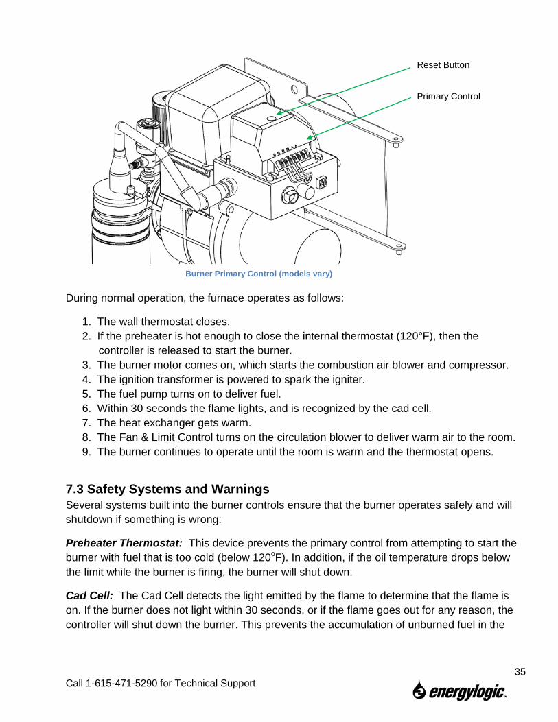
7.2 Burner Primary Control Operation The burner operation is governed by the Primary Control (shown in figure on next page). This device is pre-programmed and is not adjustable. The important interface points are as follows:
• The two T-Terminals are for the thermostat signal. To simulate a closed thermostat, you can jumper across the two T terminals with an alligator clip.
• The two F-Terminals are for the cad cell signal. The cad cell is a light sensor inside the burner that senses the flame. To simulate a flame, you can jumper across the two F terminals with an alligator clip.
Do not leave the T and F terminals jumped during normal furnace operation, as this bypasses several safety checks and may cause excessive oil to be deposited in the combustion chamber, creating a fire or explosion hazard. For the same reason, do not leave the T and F terminals jumped for more than 30 seconds if oil is being sprayed but not being burned.
• The reset button is used to reset the controller, in case of multiple failed start attempts or flameouts.
• The LED(s) (on some models) are used to indicate proper furnace operation or errors.
34
Call 1-615-471-5290 for Technical Support
During normal operation, the furnace operates as follows:
1. The wall thermostat closes. 2. If the preheater is hot enough to close the internal thermostat (120°F), then the
controller is released to start the burner. 3. The burner motor comes on, which starts the combustion air blower and compressor. 4. The ignition transformer is powered to spark the igniter. 5. The fuel pump turns on to deliver fuel. 6. Within 30 seconds the flame lights, and is recognized by the cad cell. 7. The heat exchanger gets warm. 8. The Fan & Limit Control turns on the circulation blower to deliver warm air to the room. 9. The burner continues to operate until the room is warm and the thermostat opens.
7.3 Safety Systems and Warnings Several systems built into the burner controls ensure that the burner operates safely and will shutdown if something is wrong:
Preheater Thermostat: This device prevents the primary control from attempting to start the burner with fuel that is too cold (below 120oF). In addition, if the oil temperature drops below the limit while the burner is firing, the burner will shut down.
Cad Cell: The Cad Cell detects the light emitted by the flame to determine that the flame is on. If the burner does not light within 30 seconds, or if the flame goes out for any reason, the controller will shut down the burner. This prevents the accumulation of unburned fuel in the
Primary Control
Reset Button
Burner Primary Control (models vary)
35
Call 1-615-471-5290 for Technical Support
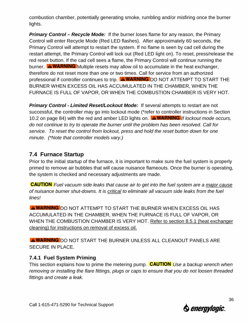
combustion chamber, potentially generating smoke, rumbling and/or misfiring once the burner lights.
Primary Control – Recycle Mode: If the burner loses flame for any reason, the Primary Control will enter Recycle Mode (Red LED flashes). After approximately 60 seconds, the Primary Control will attempt to restart the system. If no flame is seen by cad cell during the restart attempt, the Primary Control will lock out (Red LED light on). To reset, press/release the red reset button. If the cad cell sees a flame, the Primary Control will continue running the burner. Multiple resets may allow oil to accumulate in the heat exchanger, therefore do not reset more than one or two times. Call for service from an authorized professional if controller continues to trip. DO NOT ATTEMPT TO START THE BURNER WHEN EXCESS OIL HAS ACCUMULATED IN THE CHAMBER, WHEN THE FURNACE IS FULL OF VAPOR, OR WHEN THE COMBUSTION CHAMBER IS VERY HOT. Primary Control - Limited Reset/Lockout Mode: If several attempts to restart are not successful, the controller may go into lockout mode (*refer to controller instructions in Section 10.2 on page 84) with the red and amber LED lights on. If lockout mode occurs, do not continue to try to operate the burner until the problem has been resolved. Call for service. To reset the control from lockout, press and hold the reset button down for one minute. (*Note that controller models vary.)
7.4 Furnace Startup Prior to the initial startup of the furnace, it is important to make sure the fuel system is properly primed to remove air bubbles that will cause nuisance flameouts. Once the burner is operating, the system is checked and necessary adjustments are made.
Fuel vacuum side leaks that cause air to get into the fuel system are a major cause of nuisance burner shut-downs. It is critical to eliminate all vacuum side leaks from the fuel lines!
DO NOT ATTEMPT TO START THE BURNER WHEN EXCESS OIL HAS ACCUMULATED IN THE CHAMBER, WHEN THE FURNACE IS FULL OF VAPOR, OR WHEN THE COMBUSTION CHAMBER IS VERY HOT. Refer to section 8.5.1 (heat exchanger cleaning) for instructions on removal of excess oil.
DO NOT START THE BURNER UNLESS ALL CLEANOUT PANELS ARE SECURE IN PLACE.
7.4.1 Fuel System Priming This section explains how to prime the metering pump. Use a backup wrench when removing or installing the flare fittings, plugs or caps to ensure that you do not loosen threaded fittings and create a leak.
36
Call 1-615-471-5290 for Technical Support
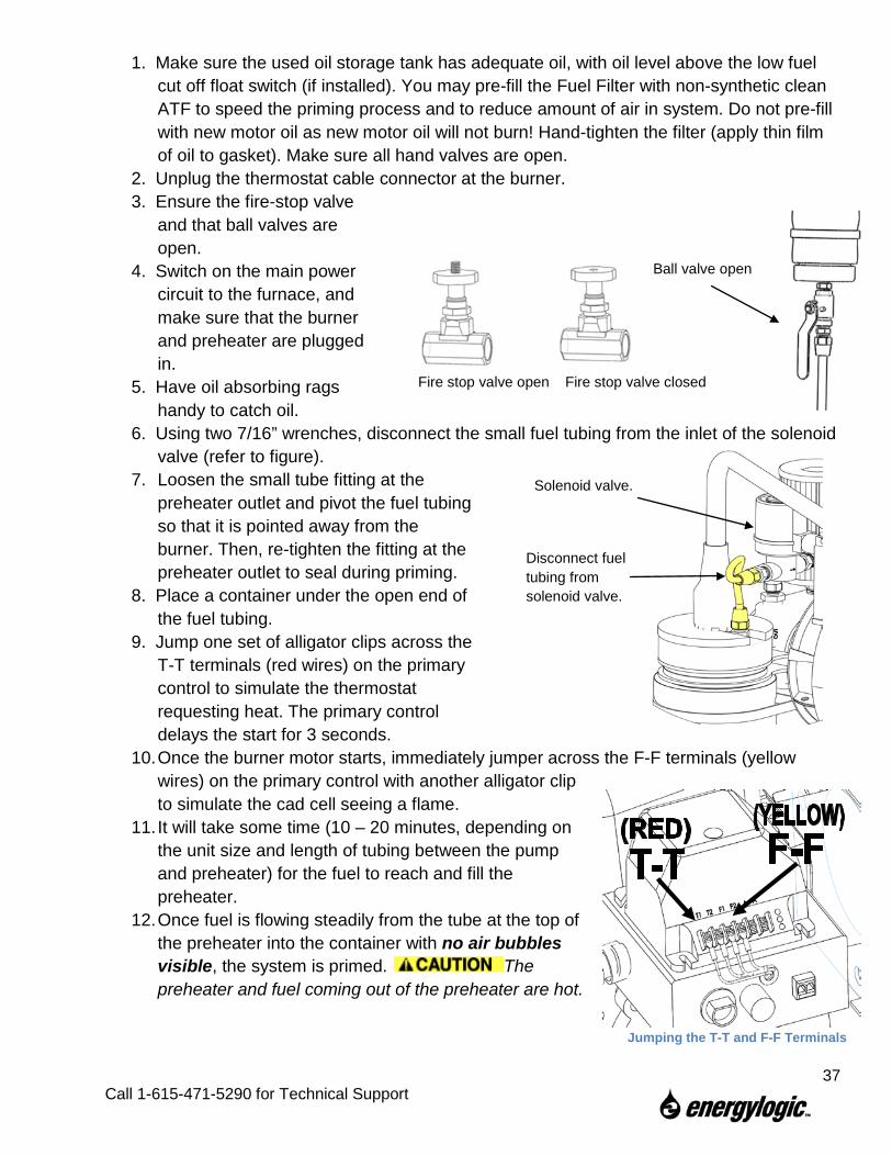
1. Make sure the used oil storage tank has adequate oil, with oil level above the low fuel cut off float switch (if installed). You may pre-fill the Fuel Filter with non-synthetic clean ATF to speed the priming process and to reduce amount of air in system. Do not pre-fill with new motor oil as new motor oil will not burn! Hand-tighten the filter (apply thin film of oil to gasket). Make sure all hand valves are open.
2. Unplug the thermostat cable connector at the burner. 3. Ensure the fire-stop valve
and that ball valves are open.
4. Switch on the main power circuit to the furnace, and make sure that the burner and preheater are plugged in.
5. Have oil absorbing rags handy to catch oil.
6. Using two 7/16” wrenches, disconnect the small fuel tubing from the inlet of the solenoid valve (refer to figure).
7. Loosen the small tube fitting at the preheater outlet and pivot the fuel tubing so that it is pointed away from the burner. Then, re-tighten the fitting at the preheater outlet to seal during priming.
8. Place a container under the open end of the fuel tubing.
9. Jump one set of alligator clips across the T-T terminals (red wires) on the primary control to simulate the thermostat requesting heat. The primary control delays the start for 3 seconds.
10. Once the burner motor starts, immediately jumper across the F-F terminals (yellow wires) on the primary control with another alligator clip to simulate the cad cell seeing a flame.
11. It will take some time (10 – 20 minutes, depending on the unit size and length of tubing between the pump and preheater) for the fuel to reach and fill the preheater.
12. Once fuel is flowing steadily from the tube at the top of the preheater into the container with no air bubbles visible, the system is primed. The preheater and fuel coming out of the preheater are hot.
Ball valve open
Fire stop valve open Fire stop valve closed
Jumping the T-T and F-F Terminals
Disconnect fuel tubing from solenoid valve.
Solenoid valve.
37
Call 1-615-471-5290 for Technical Support
13. Remove the alligator clips from the terminals. Do not leave the T-T and/or F-F terminals jumped during normal furnace operation, as this bypasses several safety checks.
14. Reconnect the fuel tubing to the solenoid valve and preheater outlet. The preheater and fuel coming out of the preheater are hot.
15. Plug the thermostat cable connector back into the burner. 16. Make sure that the preheater valve is open.
7.4.2 Starting the Furnace Prior to starting the furnace after power has turned off or the preheater unplugged, allow the preheater to heat the fuel for 20-30 minutes. The preheater thermostat circuit will close once fuel temperature reaches approximately 120°F. Once the fuel is hot, start the furnace as follows:
DO NOT ATTEMPT TO START THE BURNER WHEN EXCESS OIL HAS ACCUMULATED, WHEN THE FURNACE IS FULL OF VAPOR, OR WHEN THE COMBUSTION CHAMBER IS VERY HOT. Refer to section 8.5.1 (heat exchanger cleaning) for instructions on removal of excess oil.
DO NOT START THE BURNER UNLESS ALL CLEANOUT PANELS ARE SECURE IN PLACE.
1. Verify the Red LED (on certain models) on the primary control is not on or flashing. You may need to reset the controller by pressing the reset button.
2. Set the wall thermostat to a high temperature to send a call for heat and start the furnace.
3. It may take a few attempts for the furnace to light on the initial start, as the nozzle block will not be filled with fuel yet.
4. If the furnace will not light, proceed to the troubleshooting section of the manual or call EnergyLogic for technical support.
5. Continue to the next section for important checks and adjustments.
38
Call 1-615-471-5290 for Technical Support
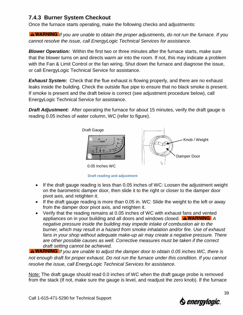
7.4.3 Burner System Checkout Once the furnace starts operating, make the following checks and adjustments:
If you are unable to obtain the proper adjustments, do not run the furnace. If you cannot resolve the issue, call EnergyLogic Technical Services for assistance.
Blower Operation: Within the first two or three minutes after the furnace starts, make sure that the blower turns on and directs warm air into the room. If not, this may indicate a problem with the Fan & Limit Control or the fan wiring. Shut down the furnace and diagnose the issue, or call EnergyLogic Technical Service for assistance.
Exhaust System: Check that the flue exhaust is flowing properly, and there are no exhaust leaks inside the building. Check the outside flue pipe to ensure that no black smoke is present. If smoke is present and the draft below is correct (see adjustment procedure below), call EnergyLogic Technical Service for assistance.
Draft Adjustment: After operating the furnace for about 15 minutes, verify the draft gauge is reading 0.05 inches of water column, WC (refer to figure).
• If the draft gauge reading is less than 0.05 inches of WC: Loosen the adjustment weight on the barometric damper door, then slide it to the right or closer to the damper door pivot axis, and retighten it.
• If the draft gauge reading is more than 0.05 in. WC: Slide the weight to the left or away from the damper door pivot axis, and retighten it.
• Verify that the reading remains at 0.05 inches of WC with exhaust fans and vented appliances on in your building and all doors and windows closed. A negative pressure inside the building may impede intake of combustion air to the burner, which may result in a hazard from smoke inhalation and/or fire. Use of exhaust fans in your shop without adequate make-up air may create a negative pressure. There are other possible causes as well. Corrective measures must be taken if the correct draft setting cannot be achieved.
If you are unable to adjust the damper door to obtain 0.05 inches WC, there is not enough draft for proper exhaust. Do not run the furnace under this condition. If you cannot resolve the issue, call EnergyLogic Technical Services for assistance.
Note: The draft gauge should read 0.0 inches of WC when the draft gauge probe is removed from the stack (If not, make sure the gauge is level, and readjust the zero knob). If the furnace
Draft reading and adjustment
0.05 Inches WC
Damper Door
Knob / Weight
Draft Gauge
39
Call 1-615-471-5290 for Technical Support
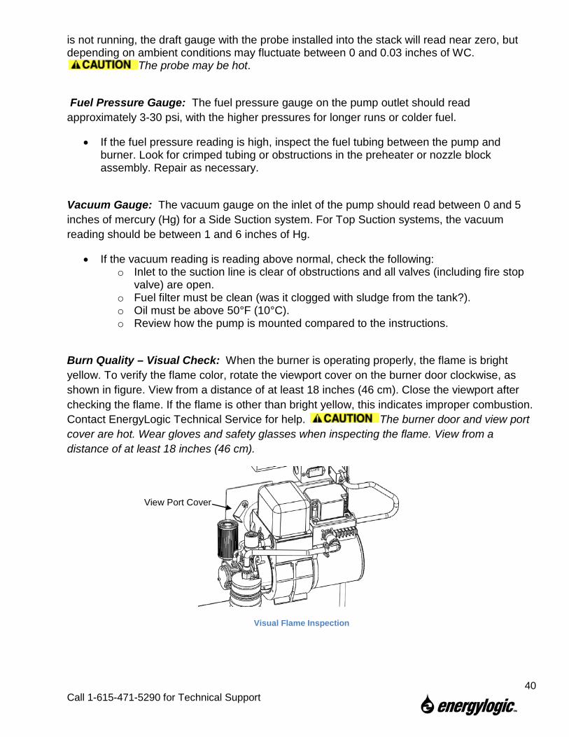
is not running, the draft gauge with the probe installed into the stack will read near zero, but depending on ambient conditions may fluctuate between 0 and 0.03 inches of WC.
The probe may be hot.
Fuel Pressure Gauge: The fuel pressure gauge on the pump outlet should read approximately 3-30 psi, with the higher pressures for longer runs or colder fuel.
• If the fuel pressure reading is high, inspect the fuel tubing between the pump and burner. Look for crimped tubing or obstructions in the preheater or nozzle block assembly. Repair as necessary.
Vacuum Gauge: The vacuum gauge on the inlet of the pump should read between 0 and 5 inches of mercury (Hg) for a Side Suction system. For Top Suction systems, the vacuum reading should be between 1 and 6 inches of Hg.
• If the vacuum reading is reading above normal, check the following: o Inlet to the suction line is clear of obstructions and all valves (including fire stop
valve) are open. o Fuel filter must be clean (was it clogged with sludge from the tank?). o Oil must be above 50°F (10°C). o Review how the pump is mounted compared to the instructions.
Burn Quality – Visual Check: When the burner is operating properly, the flame is bright yellow. To verify the flame color, rotate the viewport cover on the burner door clockwise, as shown in figure. View from a distance of at least 18 inches (46 cm). Close the viewport after checking the flame. If the flame is other than bright yellow, this indicates improper combustion. Contact EnergyLogic Technical Service for help. The burner door and view port cover are hot. Wear gloves and safety glasses when inspecting the flame. View from a distance of at least 18 inches (46 cm).
Visual Flame Inspection
View Port Cover
40
Call 1-615-471-5290 for Technical Support
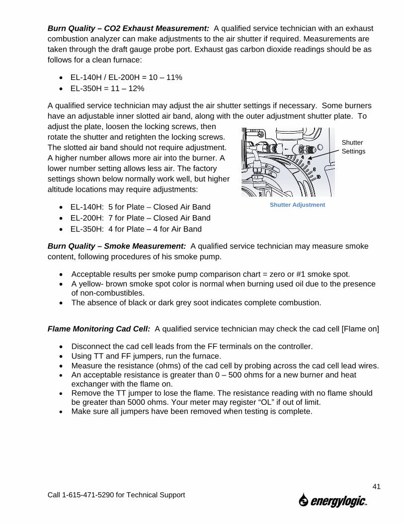
Burn Quality – CO2 Exhaust Measurement: A qualified service technician with an exhaust combustion analyzer can make adjustments to the air shutter if required. Measurements are taken through the draft gauge probe port. Exhaust gas carbon dioxide readings should be as follows for a clean furnace:
• EL-140H / EL-200H = 10 – 11% • EL-350H = 11 – 12%
A qualified service technician may adjust the air shutter settings if necessary. Some burners have an adjustable inner slotted air band, along with the outer adjustment shutter plate. To adjust the plate, loosen the locking screws, then rotate the shutter and retighten the locking screws. The slotted air band should not require adjustment. A higher number allows more air into the burner. A lower number setting allows less air. The factory settings shown below normally work well, but higher altitude locations may require adjustments:
• EL-140H: 5 for Plate – Closed Air Band • EL-200H: 7 for Plate – Closed Air Band • EL-350H: 4 for Plate – 4 for Air Band
Burn Quality – Smoke Measurement: A qualified service technician may measure smoke content, following procedures of his smoke pump.
• Acceptable results per smoke pump comparison chart = zero or #1 smoke spot. • A yellow- brown smoke spot color is normal when burning used oil due to the presence
of non-combustibles. • The absence of black or dark grey soot indicates complete combustion.
Flame Monitoring Cad Cell: A qualified service technician may check the cad cell [Flame on]
• Disconnect the cad cell leads from the FF terminals on the controller. • Using TT and FF jumpers, run the furnace. • Measure the resistance (ohms) of the cad cell by probing across the cad cell lead wires. • An acceptable resistance is greater than 0 – 500 ohms for a new burner and heat
exchanger with the flame on. • Remove the TT jumper to lose the flame. The resistance reading with no flame should
be greater than 5000 ohms. Your meter may register “OL” if out of limit. • Make sure all jumpers have been removed when testing is complete.
Shutter Settings
Shutter Adjustment
41
Call 1-615-471-5290 for Technical Support
7.5 Everyday Operation of Your EnergyLogic Used Oil Furnace Once installed and checked, operate your EnergyLogic Furnace as follows:
Daily Operation. • Set the room thermostat to the desired temperature. • You should not let the temperature of the room get below 50°F (10°C), or the oil will
become thick and may present fuel delivery issues. • To shut down the furnace in an emergency, turn off the power at the user-installed,
switched junction box or main breaker.
Manage the Used Oil. • Do not put unapproved substances into your used oil storage tank. See section 1.5.1 for
a list of approved fuels. • Monitor the bottom of your tank for water and drain it off on a regular basis. • Don’t let your oil tank run dry. Don’t risk introduction of air into the fuel delivery system.
You will save yourself much time and trouble by keeping your tank filled with oil. If you don’t have one, consider installing an optional EnergyLogic Low-Fuel Cut-Off Switch to turn off the furnace at low fuel levels.
• When filling the tank be careful not to agitate the oil so that air/sludge are not introduced into the fuel pump.
• Pre-screen the oil prior to putting it into the tank. Occasionally have your tank drained and cleaned.
Monitor the System. • After your initial set up, monitor the system gauge readings on a regular schedule to
assure that the system is stable. Record the readings and any maintenance performed in the maintenance log (refer to section 8) to track your system performance over time.
• Maintain your furnace. Regular maintenance will help to keep the furnace running reliable and efficient for many years.
Summer Blower Operation and Shutdown • Perform seasonal maintenance. • In summer months, the blower may be used to circulate room air. To run the blower fan
manually, the white button on the fan & high temperature limit controller may be pushed in. To set the controller back to automatic mode, the button may be pulled out. Make sure that the preheater is unplugged from the burner wire box if using the furnace blower in the summer.
• Refer to shutdown procedure in Section 8.6.
42
Call 1-615-471-5290 for Technical Support
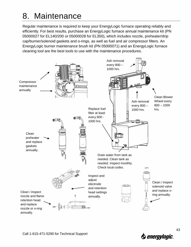
8. Maintenance Regular maintenance is required to keep your EnergyLogic furnace operating reliably and efficiently. For best results, purchase an EnergyLogic furnace annual maintenance kit (PN 05000027 for EL140/200 or 05000028 for EL350), which includes nozzle, preheater/drip cap/burner/solenoid gaskets and o-rings, as well as fuel and air compressor filters. An EnergyLogic burner maintenance brush kit (PN 05000071) and an EnergyLogic furnace cleaning tool are the best tools to use with the maintenance procedures.
Clean preheater and replace gaskets annually.
Clean / inspect solenoid valve and replace o-ring annually.
Clean / inspect nozzle and flame retention head and replace nozzle or o-ring annually.
Compressor maintenance annually
Ash removal every 800 – 1000 hrs.
Clean Blower Wheel every 800 – 1000 hrs.
Ash removal every 800 – 1000 hrs.
Drain water from tank as needed. Clean tank as needed. Inspect monthly. Check local codes.
Replace fuel filter at least every 800 -1000 hrs.
Inspect and adjust electrode and retention head settings annually.
43
Call 1-615-471-5290 for Technical Support
8.1 Service Contracts If you are not qualified or do not wish to perform the furnace maintenance yourself, contact EnergyLogic for the location of our nearest dealer or service provider. Putting a service contract in place is the best way to make sure that the required maintenance is completed regularly and your system will operate reliably when needed, saving you both time and money.
8.2 Safety Warnings – Lockout/Tagout There are many potential hazards associated with working on this equipment, including electricity, heat, heights, dust and chemicals. Make sure the main electrical circuit is off and locked out / tagged out prior to performing maintenance. Wear proper safety equipment for the tasks, including a HEPA quality dust mask to avoid inhalation of ash dust when cleaning the heat exchanger or flue. Use suitable access aids/equipment when working on the furnace. Do not climb on the furnace. General safety rules and precautions should be followed at all times to prevent any accidents that could lead to personal injury or property damage. Only those qualified should perform these tasks.
8.3 Monitoring System Performance over Time EnergyLogic recommends that you monitor and record your system gauge readings regularly over time, in order to diagnose issues that may arise. For example, if the pump vacuum gauge initially read 2 inches Hg, but over time has risen to 10 inches Hg, it is an indication that the fuel filter is most likely clogged up. Record the system gauge readings on your maintenance schedule and log. Have this log handy if you call EnergyLogic for technical support.
8.4 Maintenance Schedule and Parts The recommended maintenance interval and log is shown on the following page. Check your local codes and regulations for maintenance frequency requirements that may take precedence. Use of certain fuels or other conditions may require more frequent maintenance. Make a copy of the maintenance log and use it to record the maintenance and system performance readings over time. Contact your EnergyLogic dealer or call EnergyLogic for service parts. EnergyLogic offers convenient annual maintenance kits and cleaning tools made specifically for your furnace. Economical bulk packs of fuel and air filters are available as well.
The maintenance schedule is the minimum recommended, but if you see smoke or have trip outs then the unit must be shut down and serviced immediately before running it again. Increase the maintenance as your situation requires.
44
Call 1-615-471-5290 for Technical Support
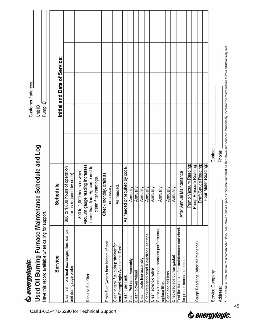
45
Call 1-615-471-5290 for Technical Support
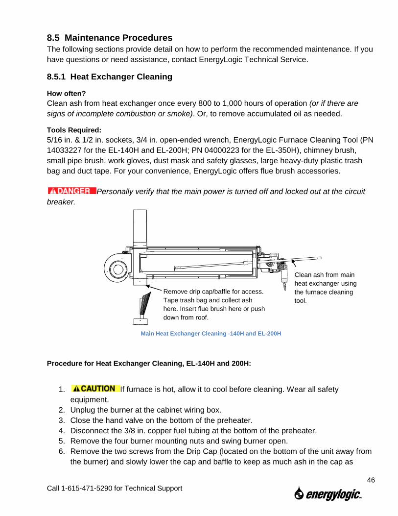
8.5 Maintenance Procedures The following sections provide detail on how to perform the recommended maintenance. If you have questions or need assistance, contact EnergyLogic Technical Service.
8.5.1 Heat Exchanger Cleaning
How often? Clean ash from heat exchanger once every 800 to 1,000 hours of operation (or if there are signs of incomplete combustion or smoke). Or, to remove accumulated oil as needed.
Tools Required: 5/16 in. & 1/2 in. sockets, 3/4 in. open-ended wrench, EnergyLogic Furnace Cleaning Tool (PN 14033227 for the EL-140H and EL-200H; PN 04000223 for the EL-350H), chimney brush, small pipe brush, work gloves, dust mask and safety glasses, large heavy-duty plastic trash bag and duct tape. For your convenience, EnergyLogic offers flue brush accessories.
Personally verify that the main power is turned off and locked out at the circuit breaker.
Main Heat Exchanger Cleaning -140H and EL-200H
Procedure for Heat Exchanger Cleaning, EL-140H and 200H:
1. If furnace is hot, allow it to cool before cleaning. Wear all safety equipment.
2. Unplug the burner at the cabinet wiring box. 3. Close the hand valve on the bottom of the preheater. 4. Disconnect the 3/8 in. copper fuel tubing at the bottom of the preheater. 5. Remove the four burner mounting nuts and swing burner open. 6. Remove the two screws from the Drip Cap (located on the bottom of the unit away from
the burner) and slowly lower the cap and baffle to keep as much ash in the cap as
Remove drip cap/baffle for access. Tape trash bag and collect ash here. Insert flue brush here or push down from roof.
Clean ash from main heat exchanger using the furnace cleaning tool.
46
Call 1-615-471-5290 for Technical Support
possible (refer to figure). Beware of falling parts that may create a crush hazard.
7. Tape the opening of a trash bag to the Drip Leg with duct tape, so ash will fall into the trash bag.
8. Accessing the interior of the heat exchanger through the burner opening, use the furnace cleaning tool or brush to push the ash to the opposite end of the exchanger, out the clean out port, and into the trash bag. A shop vacuum may also be used to remove ash.
9. Gently tap the flue pipe and allow ash to fall into the trash bag. 10. Remove the trash bag and insert the chimney brush into the flue. 11. Reattach the trash bag, then reach through the bag, grab the brush and clean the ash
from the flue pipe by running it through the flue pipe. Clean all flue pipe from other access points if extension rods do not reach from the bottom of the furnace.
12. Remove the trash bag/brush and properly dispose of the ash. 13. Inspect the cleaned heat exchanger and flue. If damaged, replace damaged parts. 14. Inspect the Drip Cap gasket. If damaged, replace the gasket (PN 20933118). 15. Reattach the Drip Cap. Make sure that the baffle is facing the burner (refer to figure).
Use existing screw holes and replace screws. 16. Inspect Burner Gasket. If damaged, replace the gasket (PN 20910103). 17. Swing the burner over the four studs to close and reinstall the nuts. 18. Reinstall the fuel tubing on the preheater and open the hand valve. 19. Make sure to perform start up (7.4.2) and system checks (7.4.3) after
every maintenance cycle. Record the checks, maintenance performed, and gauge readings in the maintenance log.
Procedure for Heat Exchanger Cleaning, EL-350H:
1. If furnace is hot, allow it to cool before cleaning. Wear all safety equipment.
2. Unplug the burner at the cabinet wiring box. 3. Close the hand valve on the bottom of the preheater. 4. Disconnect the 3/8 in. copper fuel tubing at the bottom of the preheater. 5. Remove the four burner mounting nuts and swing burner open. 6. Remove the two screws from the Drip Cap (located on the bottom of the unit away from
the burner) and slowly lower the cap off of the clean out port, keeping as much ash in the cap as possible.
7. Tape the opening of a trash bag to the clean out port, so ash will fall into the trash bag. 8. Accessing the interior of the heat exchanger through the burner opening, use the
furnace cleaning tool (optional accessory – part # 04000223) or brush to push the ash to the opposite end of the exchanger into the trash bag. A shop vacuum may also be
47
Call 1-615-471-5290 for Technical Support
used to remove ash. Gently tap the flue pipe and allow ash to fall into the heat exchanger and trash bag.
9. Make sure to clean the ash from the top of the baffle (where the flue pipe connects). 10. The flue pipe should be cleaned at least once a year, and whenever it becomes clogged
with ash and/or soot. 11. The flue pipe can be cleaned with a flue brush from the roof by removing the rain cap,
or from the bottom cleaning port by removing the blower from the cabinet and the baffle from the heat exchanger.
12. To remove the blower from the cabinet, make sure the power is off. Then disconnect the blower power wires in the junction box. Then remove the screws holding the blower to the cabinet and carefully slide it off ( Blower is heavy.).
Personally verify that the main power is turned off and locked out at the circuit breaker. 13. Remove the five nuts holding the baffle in the heat exchanger and pull the handle to
slide it out. 14. Remove the trash bag and insert the chimney brush into the flue. 15. Reattach the trash bag, then reach through the bag, grab the brush and clean the ash
from the flue pipe by running it up through the flue pipe. Clean all flue pipe from other access points if extension rods do not reach from the bottom of the furnace.
16. Remove the trash bag/brush and properly dispose of the ash. 17. Inspect the cleaned heat exchanger and flue. If damaged, replace damaged parts. 18. Inspect the Drip Cap gasket. If damaged, replace the gasket (PN 06000578). 19. Reattach the Drip Cap. Use existing screw holes and replace screws. 20. Clean and reinstall the baffle. Replace the baffle gasket if necessary (PN 06000584). 21. Clean up any ash that spilled inside the cabinet. 22. Clean and reinstall the blower (see next section), and reconnect the blower power
wires. 23. Inspect Burner Gasket. If damaged, replace the gasket (PN 20910103). 24. Swing the burner over the four studs to close and reinstall the nuts. 25. Reinstall the fuel tubing on the preheater and open the hand valve. 26. Make sure to perform start up (7.4.2) and system checks (7.4.3) after
every maintenance cycle. Record the checks, maintenance performed, and gauge readings in the maintenance log.
48
Call 1-615-471-5290 for Technical Support
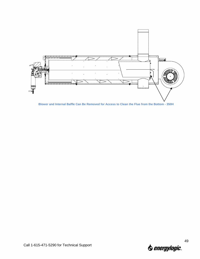
Blower and Internal Baffle Can Be Removed for Access to Clean the Flue from the Bottom - 350H
49
Call 1-615-471-5290 for Technical Support
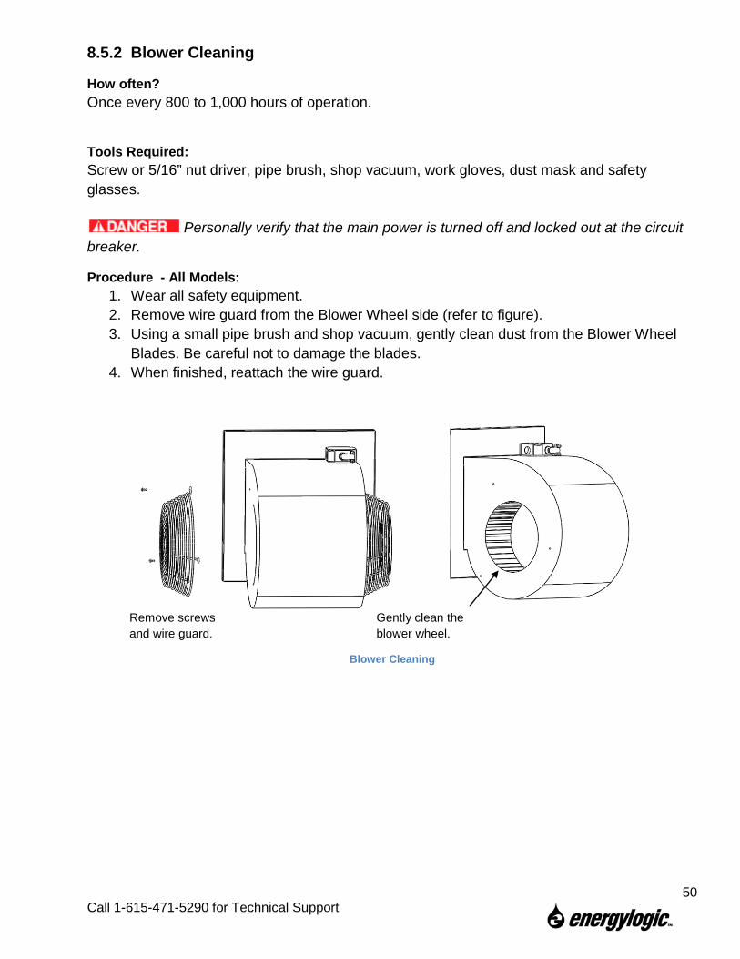
8.5.2 Blower Cleaning
How often? Once every 800 to 1,000 hours of operation.
Tools Required: Screw or 5/16” nut driver, pipe brush, shop vacuum, work gloves, dust mask and safety glasses.
Personally verify that the main power is turned off and locked out at the circuit breaker.
Procedure - All Models: 1. Wear all safety equipment. 2. Remove wire guard from the Blower Wheel side (refer to figure). 3. Using a small pipe brush and shop vacuum, gently clean dust from the Blower Wheel
Blades. Be careful not to damage the blades. 4. When finished, reattach the wire guard.
Blower Cleaning
Remove screws and wire guard.
Gently clean the blower wheel.
50
Call 1-615-471-5290 for Technical Support
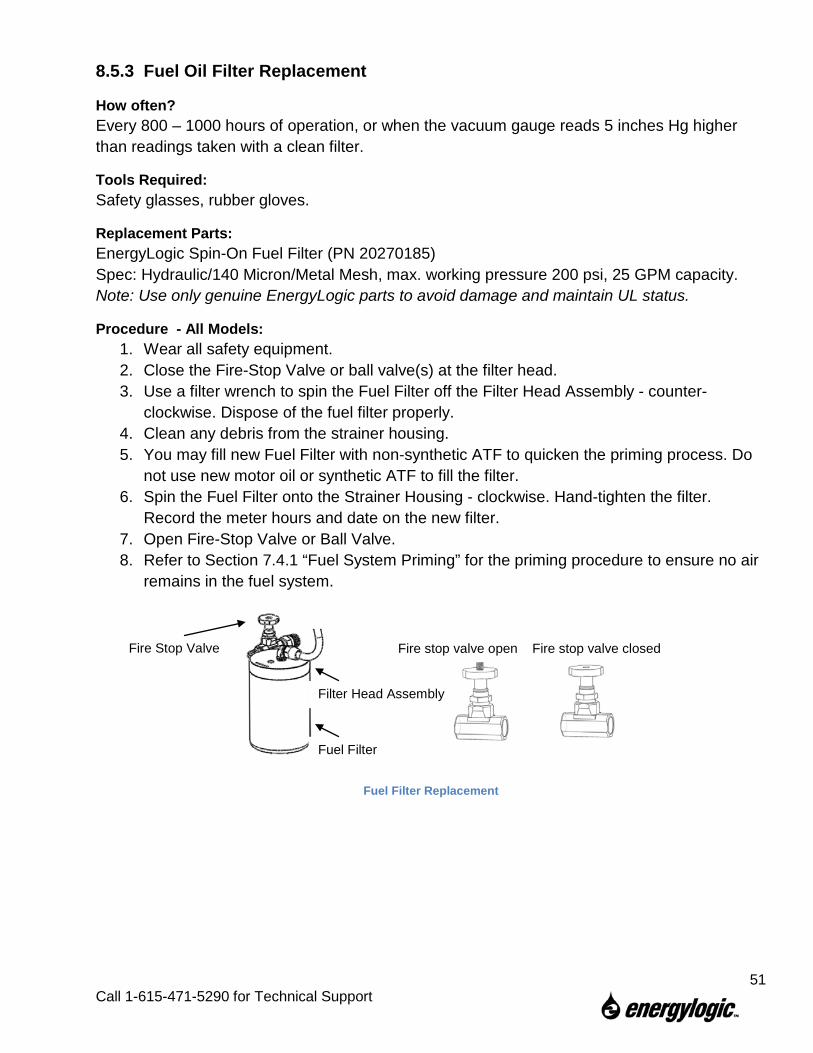
8.5.3 Fuel Oil Filter Replacement
How often? Every 800 – 1000 hours of operation, or when the vacuum gauge reads 5 inches Hg higher than readings taken with a clean filter.
Tools Required: Safety glasses, rubber gloves.
Replacement Parts: EnergyLogic Spin-On Fuel Filter (PN 20270185) Spec: Hydraulic/140 Micron/Metal Mesh, max. working pressure 200 psi, 25 GPM capacity. Note: Use only genuine EnergyLogic parts to avoid damage and maintain UL status.
Procedure - All Models: 1. Wear all safety equipment. 2. Close the Fire-Stop Valve or ball valve(s) at the filter head. 3. Use a filter wrench to spin the Fuel Filter off the Filter Head Assembly - counter-
clockwise. Dispose of the fuel filter properly. 4. Clean any debris from the strainer housing. 5. You may fill new Fuel Filter with non-synthetic ATF to quicken the priming process. Do
not use new motor oil or synthetic ATF to fill the filter. 6. Spin the Fuel Filter onto the Strainer Housing - clockwise. Hand-tighten the filter.
Record the meter hours and date on the new filter. 7. Open Fire-Stop Valve or Ball Valve. 8. Refer to Section 7.4.1 “Fuel System Priming” for the priming procedure to ensure no air
remains in the fuel system.
Fuel Filter Replacement
Fire stop valve open Fire stop valve closed
Filter Head Assembly
Fuel Filter
Fire Stop Valve
51
Call 1-615-471-5290 for Technical Support
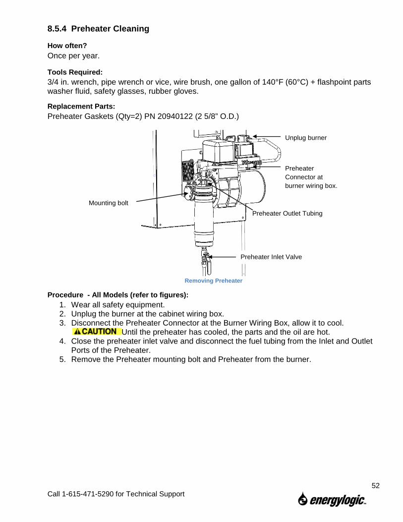
8.5.4 Preheater Cleaning
How often? Once per year.
Tools Required: 3/4 in. wrench, pipe wrench or vice, wire brush, one gallon of 140°F (60°C) + flashpoint parts washer fluid, safety glasses, rubber gloves.
Replacement Parts: Preheater Gaskets (Qty=2) PN 20940122 (2 5/8” O.D.)
Removing Preheater
Procedure - All Models (refer to figures): 1. Wear all safety equipment. 2. Unplug the burner at the cabinet wiring box. 3. Disconnect the Preheater Connector at the Burner Wiring Box, allow it to cool.
Until the preheater has cooled, the parts and the oil are hot. 4. Close the preheater inlet valve and disconnect the fuel tubing from the Inlet and Outlet
Ports of the Preheater. 5. Remove the Preheater mounting bolt and Preheater from the burner.
Unplug burner
Preheater Inlet Valve
Preheater Outlet Tubing
Preheater Connector at burner wiring box.
Mounting bolt
52
Call 1-615-471-5290 for Technical Support
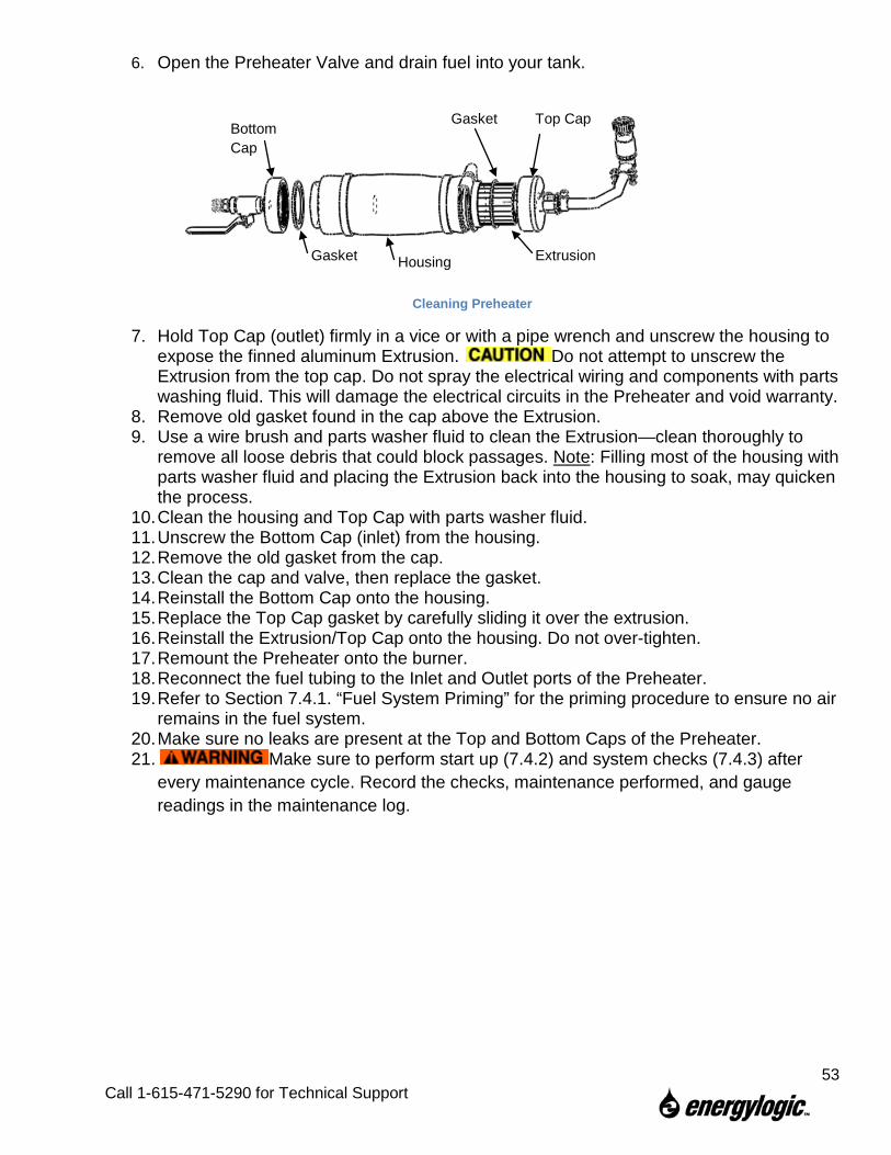
6. Open the Preheater Valve and drain fuel into your tank.
Cleaning Preheater
7. Hold Top Cap (outlet) firmly in a vice or with a pipe wrench and unscrew the housing to expose the finned aluminum Extrusion. Do not attempt to unscrew the Extrusion from the top cap. Do not spray the electrical wiring and components with parts washing fluid. This will damage the electrical circuits in the Preheater and void warranty.
8. Remove old gasket found in the cap above the Extrusion. 9. Use a wire brush and parts washer fluid to clean the Extrusion—clean thoroughly to
remove all loose debris that could block passages. Note: Filling most of the housing with parts washer fluid and placing the Extrusion back into the housing to soak, may quicken the process.
10. Clean the housing and Top Cap with parts washer fluid. 11. Unscrew the Bottom Cap (inlet) from the housing. 12. Remove the old gasket from the cap. 13. Clean the cap and valve, then replace the gasket. 14. Reinstall the Bottom Cap onto the housing. 15. Replace the Top Cap gasket by carefully sliding it over the extrusion. 16. Reinstall the Extrusion/Top Cap onto the housing. Do not over-tighten. 17. Remount the Preheater onto the burner. 18. Reconnect the fuel tubing to the Inlet and Outlet ports of the Preheater. 19. Refer to Section 7.4.1. “Fuel System Priming” for the priming procedure to ensure no air
remains in the fuel system. 20. Make sure no leaks are present at the Top and Bottom Caps of the Preheater. 21. Make sure to perform start up (7.4.2) and system checks (7.4.3) after
every maintenance cycle. Record the checks, maintenance performed, and gauge readings in the maintenance log.
Top Cap
Extrusion
Gasket
Gasket
Bottom Cap
Housing
53
Call 1-615-471-5290 for Technical Support
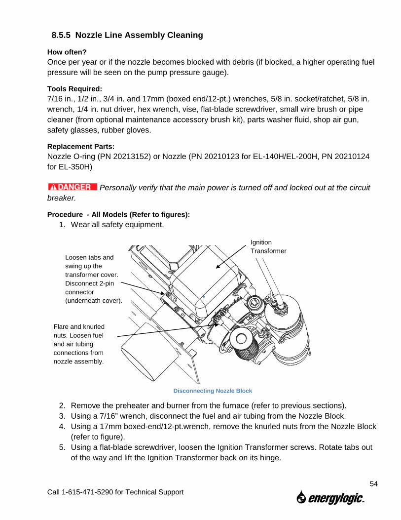
8.5.5 Nozzle Line Assembly Cleaning
How often? Once per year or if the nozzle becomes blocked with debris (if blocked, a higher operating fuel pressure will be seen on the pump pressure gauge).
Tools Required: 7/16 in., 1/2 in., 3/4 in. and 17mm (boxed end/12-pt.) wrenches, 5/8 in. socket/ratchet, 5/8 in. wrench, 1/4 in. nut driver, hex wrench, vise, flat-blade screwdriver, small wire brush or pipe cleaner (from optional maintenance accessory brush kit), parts washer fluid, shop air gun, safety glasses, rubber gloves.
Replacement Parts: Nozzle O-ring (PN 20213152) or Nozzle (PN 20210123 for EL-140H/EL-200H, PN 20210124 for EL-350H)
Personally verify that the main power is turned off and locked out at the circuit breaker.
Procedure - All Models (Refer to figures): 1. Wear all safety equipment.
2. Remove the preheater and burner from the furnace (refer to previous sections). 3. Using a 7/16” wrench, disconnect the fuel and air tubing from the Nozzle Block. 4. Using a 17mm boxed-end/12-pt.wrench, remove the knurled nuts from the Nozzle Block
(refer to figure). 5. Using a flat-blade screwdriver, loosen the Ignition Transformer screws. Rotate tabs out
of the way and lift the Ignition Transformer back on its hinge.
Disconnecting Nozzle Block
Flare and knurled nuts. Loosen fuel and air tubing connections from nozzle assembly.
Ignition Transformer
Loosen tabs and swing up the transformer cover. Disconnect 2-pin connector (underneath cover).
54
Call 1-615-471-5290 for Technical Support
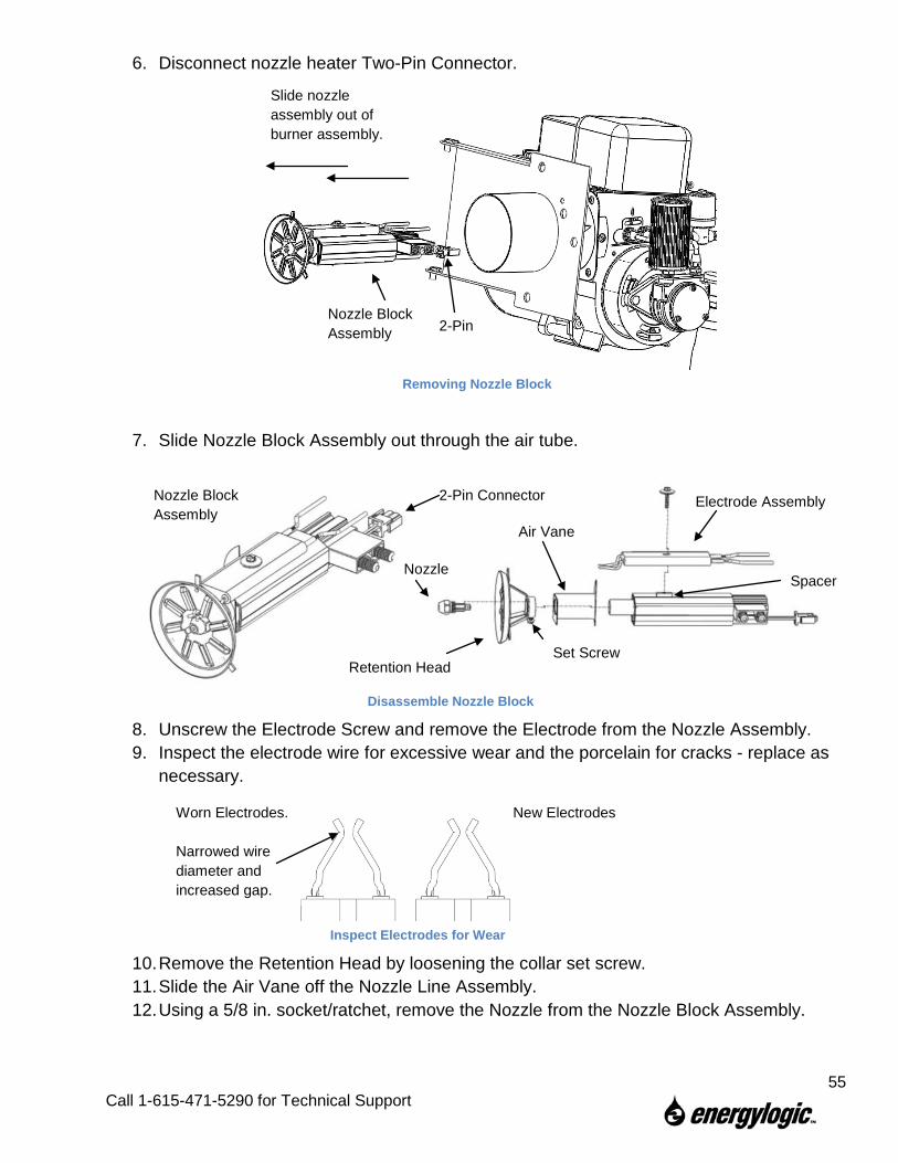
6. Disconnect nozzle heater Two-Pin Connector.
7. Slide Nozzle Block Assembly out through the air tube.
8. Unscrew the Electrode Screw and remove the Electrode from the Nozzle Assembly. 9. Inspect the electrode wire for excessive wear and the porcelain for cracks - replace as
necessary.
10. Remove the Retention Head by loosening the collar set screw. 11. Slide the Air Vane off the Nozzle Line Assembly. 12. Using a 5/8 in. socket/ratchet, remove the Nozzle from the Nozzle Block Assembly.
Slide nozzle assembly out of burner assembly.
Removing Nozzle Block
Inspect Electrodes for Wear
Disassemble Nozzle Block
Set Screw Retention Head
Nozzle Block Assembly
Air Vane
Electrode Assembly
Nozzle
2-Pin Connector
Nozzle Block Assembly
New Electrodes Worn Electrodes. Narrowed wire diameter and increased gap.
2-Pin
Spacer
55
Call 1-615-471-5290 for Technical Support
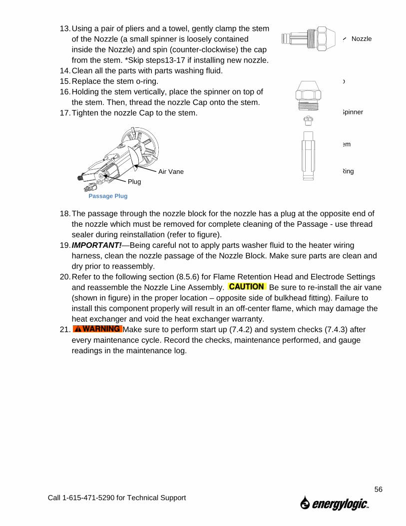
13. Using a pair of pliers and a towel, gently clamp the stem of the Nozzle (a small spinner is loosely contained inside the Nozzle) and spin (counter-clockwise) the cap from the stem. *Skip steps13-17 if installing new nozzle.
14. Clean all the parts with parts washing fluid. 15. Replace the stem o-ring. 16. Holding the stem vertically, place the spinner on top of
the stem. Then, thread the nozzle Cap onto the stem. 17. Tighten the nozzle Cap to the stem.
18. The passage through the nozzle block for the nozzle has a plug at the opposite end of the nozzle which must be removed for complete cleaning of the Passage - use thread sealer during reinstallation (refer to figure).
19. IMPORTANT!—Being careful not to apply parts washer fluid to the heater wiring harness, clean the nozzle passage of the Nozzle Block. Make sure parts are clean and dry prior to reassembly.
20. Refer to the following section (8.5.6) for Flame Retention Head and Electrode Settings and reassemble the Nozzle Line Assembly. Be sure to re-install the air vane (shown in figure) in the proper location – opposite side of bulkhead fitting). Failure to install this component properly will result in an off-center flame, which may damage the heat exchanger and void the heat exchanger warranty.
21. Make sure to perform start up (7.4.2) and system checks (7.4.3) after every maintenance cycle. Record the checks, maintenance performed, and gauge readings in the maintenance log.
Disassemble Nozzle Passage Plug
Plug
Nozzle
Cap
Spinner
Stem
O-Ring Air Vane
56
Call 1-615-471-5290 for Technical Support
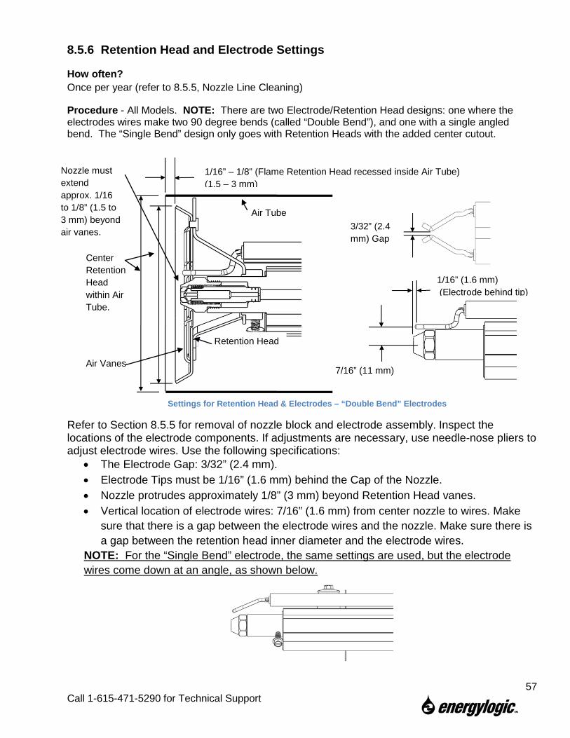
8.5.6 Retention Head and Electrode Settings
How often? Once per year (refer to 8.5.5, Nozzle Line Cleaning)
Procedure - All Models. NOTE: There are two Electrode/Retention Head designs: one where the electrodes wires make two 90 degree bends (called “Double Bend”), and one with a single angled bend. The “Single Bend” design only goes with Retention Heads with the added center cutout.
Refer to Section 8.5.5 for removal of nozzle block and electrode assembly. Inspect the locations of the electrode components. If adjustments are necessary, use needle-nose pliers to adjust electrode wires. Use the following specifications:
• The Electrode Gap: 3/32” (2.4 mm). • Electrode Tips must be 1/16” (1.6 mm) behind the Cap of the Nozzle. • Nozzle protrudes approximately 1/8” (3 mm) beyond Retention Head vanes. • Vertical location of electrode wires: 7/16” (1.6 mm) from center nozzle to wires. Make
sure that there is a gap between the electrode wires and the nozzle. Make sure there is a gap between the retention head inner diameter and the electrode wires.
NOTE: For the “Single Bend” electrode, the same settings are used, but the electrode wires come down at an angle, as shown below.
3/32” (2.4 mm) Gap
1/16” (1.6 mm) (Electrode behind tip)
1/16” – 1/8” (Flame Retention Head recessed inside Air Tube) (1.5 – 3 mm)
Retention Head
Air Tube
Center Retention Head within Air Tube.
Nozzle must extend approx. 1/16 to 1/8” (1.5 to 3 mm) beyond air vanes.
Air Vanes
Settings for Retention Head & Electrodes – “Double Bend” Electrodes
7/16” (11 mm)
57
Call 1-615-471-5290 for Technical Support
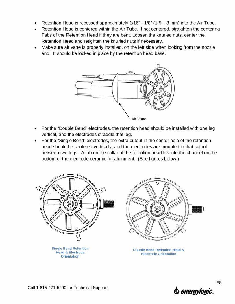
• Retention Head is recessed approximately 1/16” - 1/8” (1.5 – 3 mm) into the Air Tube. • Retention Head is centered within the Air Tube. If not centered, straighten the centering
Tabs of the Retention Head if they are bent. Loosen the knurled nuts, center the Retention Head and retighten the knurled nuts if necessary.
• Make sure air vane is properly installed, on the left side when looking from the nozzle end. It should be locked in place by the retention head base.
• For the “Double Bend” electrodes, the retention head should be installed with one leg vertical, and the electrodes straddle that leg.
• For the “Single Bend” electrodes, the extra cutout in the center hole of the retention head should be centered vertically, and the electrodes are mounted in that cutout between two legs. A tab on the collar of the retention head fits into the channel on the bottom of the electrode ceramic for alignment. (See figures below.)
Air Vane
Single Bend Retention Head & Electrode
Orientation
Double Bend Retention Head & Electrode Orientation
58
Call 1-615-471-5290 for Technical Support
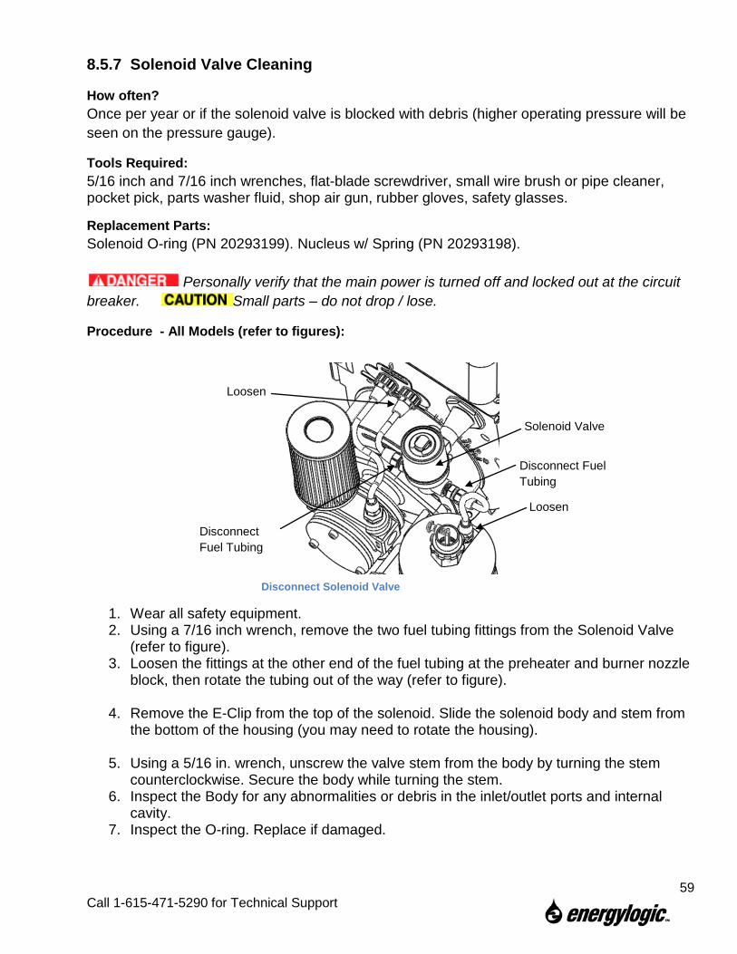
8.5.7 Solenoid Valve Cleaning
How often? Once per year or if the solenoid valve is blocked with debris (higher operating pressure will be seen on the pressure gauge).
Tools Required: 5/16 inch and 7/16 inch wrenches, flat-blade screwdriver, small wire brush or pipe cleaner, pocket pick, parts washer fluid, shop air gun, rubber gloves, safety glasses.
Replacement Parts: Solenoid O-ring (PN 20293199). Nucleus w/ Spring (PN 20293198).
Personally verify that the main power is turned off and locked out at the circuit breaker. Small parts – do not drop / lose.
Procedure - All Models (refer to figures):
1. Wear all safety equipment. 2. Using a 7/16 inch wrench, remove the two fuel tubing fittings from the Solenoid Valve
(refer to figure). 3. Loosen the fittings at the other end of the fuel tubing at the preheater and burner nozzle
block, then rotate the tubing out of the way (refer to figure).
4. Remove the E-Clip from the top of the solenoid. Slide the solenoid body and stem from the bottom of the housing (you may need to rotate the housing).
5. Using a 5/16 in. wrench, unscrew the valve stem from the body by turning the stem
counterclockwise. Secure the body while turning the stem. 6. Inspect the Body for any abnormalities or debris in the inlet/outlet ports and internal
cavity. 7. Inspect the O-ring. Replace if damaged.
Loosen
Loosen
Disconnect Fuel Tubing
Disconnect Fuel Tubing
Solenoid Valve
Disconnect Solenoid Valve
59
Call 1-615-471-5290 for Technical Support
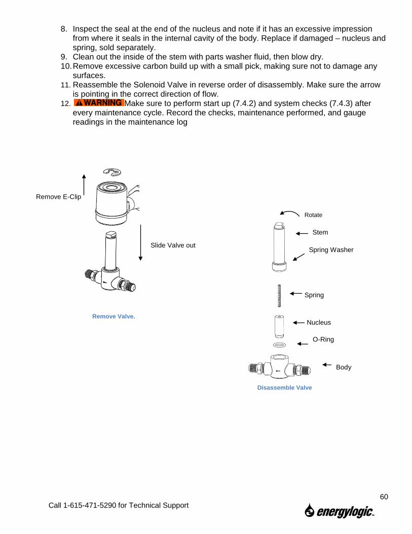
8. Inspect the seal at the end of the nucleus and note if it has an excessive impression from where it seals in the internal cavity of the body. Replace if damaged – nucleus and spring, sold separately.
9. Clean out the inside of the stem with parts washer fluid, then blow dry. 10. Remove excessive carbon build up with a small pick, making sure not to damage any
surfaces. 11. Reassemble the Solenoid Valve in reverse order of disassembly. Make sure the arrow
is pointing in the correct direction of flow. 12. Make sure to perform start up (7.4.2) and system checks (7.4.3) after
every maintenance cycle. Record the checks, maintenance performed, and gauge readings in the maintenance log
Remove E-Clip
Slide Valve out
Body
O-Ring
Nucleus
Spring
Spring Washer
Stem
Rotate
Remove Valve.
Disassemble Valve
60
Call 1-615-471-5290 for Technical Support
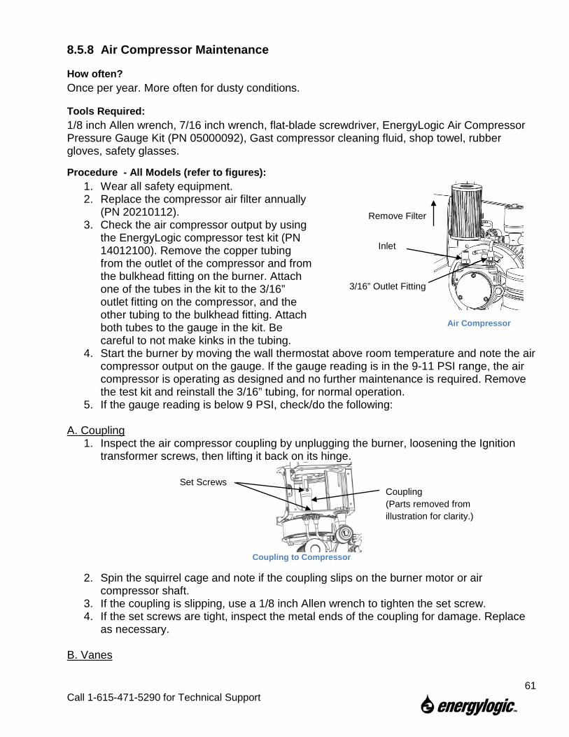
8.5.8 Air Compressor Maintenance
How often? Once per year. More often for dusty conditions.
Tools Required: 1/8 inch Allen wrench, 7/16 inch wrench, flat-blade screwdriver, EnergyLogic Air Compressor Pressure Gauge Kit (PN 05000092), Gast compressor cleaning fluid, shop towel, rubber gloves, safety glasses.
Procedure - All Models (refer to figures): 1. Wear all safety equipment. 2. Replace the compressor air filter annually
(PN 20210112). 3. Check the air compressor output by using
the EnergyLogic compressor test kit (PN 14012100). Remove the copper tubing from the outlet of the compressor and from the bulkhead fitting on the burner. Attach one of the tubes in the kit to the 3/16” outlet fitting on the compressor, and the other tubing to the bulkhead fitting. Attach both tubes to the gauge in the kit. Be careful to not make kinks in the tubing.
4. Start the burner by moving the wall thermostat above room temperature and note the air compressor output on the gauge. If the gauge reading is in the 9-11 PSI range, the air compressor is operating as designed and no further maintenance is required. Remove the test kit and reinstall the 3/16” tubing, for normal operation.
5. If the gauge reading is below 9 PSI, check/do the following: A. Coupling
1. Inspect the air compressor coupling by unplugging the burner, loosening the Ignition transformer screws, then lifting it back on its hinge.
Coupling to Compressor
2. Spin the squirrel cage and note if the coupling slips on the burner motor or air compressor shaft.
3. If the coupling is slipping, use a 1/8 inch Allen wrench to tighten the set screw. 4. If the set screws are tight, inspect the metal ends of the coupling for damage. Replace
as necessary. B. Vanes
Air Compressor
Coupling (Parts removed from illustration for clarity.)
Set Screws
Remove Filter
Inlet
3/16” Outlet Fitting
61
Call 1-615-471-5290 for Technical Support
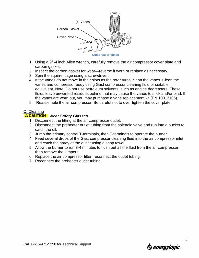
Compressor Vanes
1. Using a 9/64 inch Allen wrench, carefully remove the air compressor cover plate and carbon gasket.
2. Inspect the carbon gasket for wear—reverse if worn or replace as necessary. 3. Spin the squirrel cage using a screwdriver. 4. If the vanes do not move in their slots as the rotor turns, clean the vanes. Clean the
vanes and compressor body using Gast compressor cleaning fluid or suitable equivalent. Note: Do not use petroleum solvents, such as engine degreasers. These fluids leave unwanted residues behind that may cause the vanes to stick and/or bind. If the vanes are worn out, you may purchase a vane replacement kit (PN 10013106).
5. Reassemble the air compressor. Be careful not to over-tighten the cover plate.
C. Cleaning Wear Safety Glasses.
1. Disconnect the fitting at the air compressor outlet. 2. Disconnect the preheater outlet tubing from the solenoid valve and run into a bucket to
catch the oil. 3. Jump the primary control T-terminals, then F-terminals to operate the burner. 4. Feed several drops of the Gast compressor cleaning fluid into the air compressor inlet
and catch the spray at the outlet using a shop towel. 5. Allow the burner to run 3-4 minutes to flush out all the fluid from the air compressor,
then remove the jumpers. 6. Replace the air compressor filter, reconnect the outlet tubing. 7. Reconnect the preheater outlet tubing.
Cover Plate
Carbon Gasket
(4) Vanes
62
Call 1-615-471-5290 for Technical Support
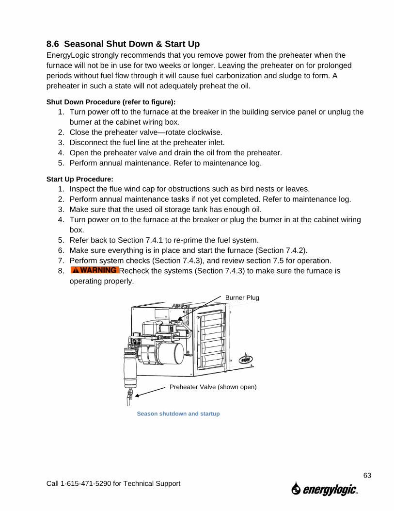
8.6 Seasonal Shut Down & Start Up EnergyLogic strongly recommends that you remove power from the preheater when the furnace will not be in use for two weeks or longer. Leaving the preheater on for prolonged periods without fuel flow through it will cause fuel carbonization and sludge to form. A preheater in such a state will not adequately preheat the oil.
Shut Down Procedure (refer to figure): 1. Turn power off to the furnace at the breaker in the building service panel or unplug the
burner at the cabinet wiring box. 2. Close the preheater valve—rotate clockwise. 3. Disconnect the fuel line at the preheater inlet. 4. Open the preheater valve and drain the oil from the preheater. 5. Perform annual maintenance. Refer to maintenance log.
Start Up Procedure: 1. Inspect the flue wind cap for obstructions such as bird nests or leaves. 2. Perform annual maintenance tasks if not yet completed. Refer to maintenance log. 3. Make sure that the used oil storage tank has enough oil. 4. Turn power on to the furnace at the breaker or plug the burner in at the cabinet wiring
box. 5. Refer back to Section 7.4.1 to re-prime the fuel system. 6. Make sure everything is in place and start the furnace (Section 7.4.2). 7. Perform system checks (Section 7.4.3), and review section 7.5 for operation. 8. Recheck the systems (Section 7.4.3) to make sure the furnace is
operating properly.
Burner Plug
Preheater Valve (shown open)
Season shutdown and startup
63
Call 1-615-471-5290 for Technical Support
9. Troubleshooting Your EnergyLogic furnace is designed and built for years of reliable service with regular maintenance. Should you experience trouble, refer to this section for troubleshooting guidance. A qualified serviceman may perform the tests in this section.
Do not tamper with the unit or controls – call your service technician or EnergyLogic for support.
Only qualified servicemen are to perform the testing procedures. Testing may include working with high voltage electricity, which if mishandled may cause serious injury or death.
Start Here – First Steps of Trouble Shooting. It has been our experience that many problems can be traced to improper installation, improper maintenance, or unintended results from changes made to the system or surrounding structures. So, the first steps in troubleshooting shall always begin with the following:
1. Verify installation and environmental factors. Remember that even if the original installation was properly performed, there can be unintended results from changes made to the building or structure. Common things to verify are:
a. Is the fuel in the tank low? Has it run dry, and the pump lost prime? b. Fuel Pump and Filter Installation. Dirty Filter? c. Fuel condition changed (bad fuel, water in fuel)? d. Adequate combustion and make up air. Have exhaust fans or other devices been
added to the building that may create a negative pressure within the building? Has another fuel burning appliance been added to the building or room? Consider make up air requirements for all appliances.
e. Exhaust Flue System: Check draft setting. Have changes taken place on the roof that might affect the flue stack? Any obstructions (birds nest, etc.).
f. Is the circuit still dedicated, or has it been compromised by the addition of other appliances to the circuit? Is the power clean?
g. Do unauthorized persons have access to the system? Have the controls been tampered with? Check factory settings (start up section).
2. Verify maintenance. If maintenance has not been performed timely and properly – STOP – perform ALL maintenance (Sec. 8) before troubleshooting. Smoke, soot, trouble in lighting-off or tripping out can all be caused by lack of maintenance or improper maintenance.
64
Call 1-615-471-5290 for Technical Support
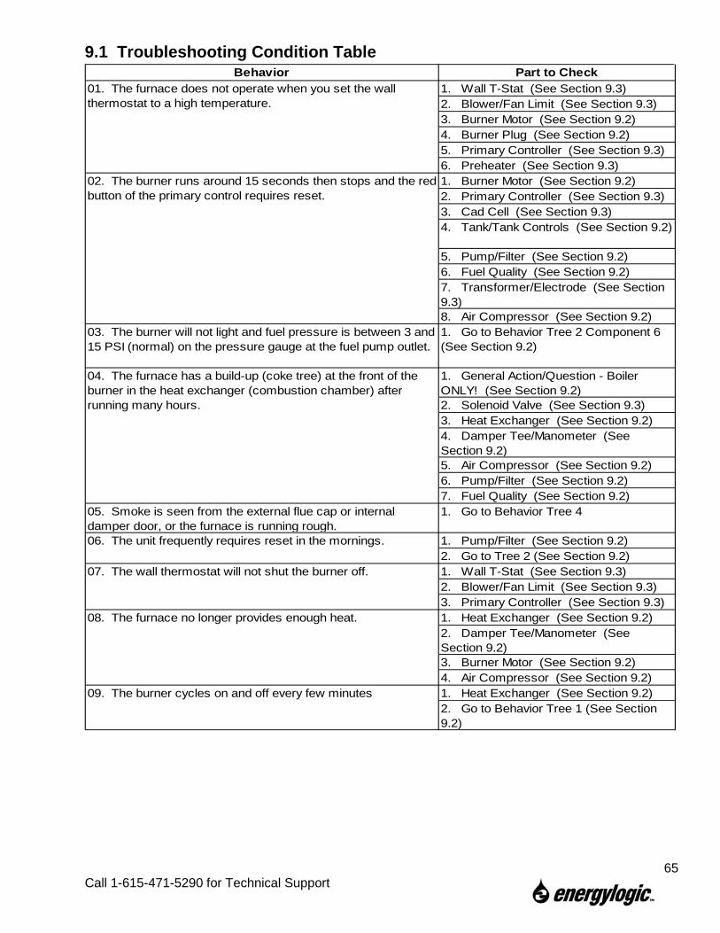
9.1 Troubleshooting Condition Table Behavior Part to Check
1. Wall T-Stat (See Section 9.3)2. Blower/Fan Limit (See Section 9.3)3. Burner Motor (See Section 9.2)4. Burner Plug (See Section 9.2)5. Primary Controller (See Section 9.3)6. Preheater (See Section 9.3)1. Burner Motor (See Section 9.2)2. Primary Controller (See Section 9.3)3. Cad Cell (See Section 9.3)4. Tank/Tank Controls (See Section 9.2)
5. Pump/Filter (See Section 9.2)6. Fuel Quality (See Section 9.2)7. Transformer/Electrode (See Section 9.3)8. Air Compressor (See Section 9.2)
03. The burner will not light and fuel pressure is between 3 and 15 PSI (normal) on the pressure gauge at the fuel pump outlet.
1. Go to Behavior Tree 2 Component 6 (See Section 9.2)
1. General Action/Question - Boiler ONLY! (See Section 9.2)2. Solenoid Valve (See Section 9.3)3. Heat Exchanger (See Section 9.2)4. Damper Tee/Manometer (See Section 9.2)5. Air Compressor (See Section 9.2)6. Pump/Filter (See Section 9.2)7. Fuel Quality (See Section 9.2)
05. Smoke is seen from the external flue cap or internal damper door, or the furnace is running rough.
1. Go to Behavior Tree 4
1. Pump/Filter (See Section 9.2)2. Go to Tree 2 (See Section 9.2)1. Wall T-Stat (See Section 9.3)2. Blower/Fan Limit (See Section 9.3)3. Primary Controller (See Section 9.3)1. Heat Exchanger (See Section 9.2)2. Damper Tee/Manometer (See Section 9.2)3. Burner Motor (See Section 9.2)4. Air Compressor (See Section 9.2)1. Heat Exchanger (See Section 9.2)2. Go to Behavior Tree 1 (See Section 9.2)
09. The burner cycles on and off every few minutes
01. The furnace does not operate when you set the wall thermostat to a high temperature.
02. The burner runs around 15 seconds then stops and the red button of the primary control requires reset.
04. The furnace has a build-up (coke tree) at the front of the burner in the heat exchanger (combustion chamber) after running many hours.
06. The unit frequently requires reset in the mornings.
07. The wall thermostat will not shut the burner off.
08. The furnace no longer provides enough heat.
65
Call 1-615-471-5290 for Technical Support
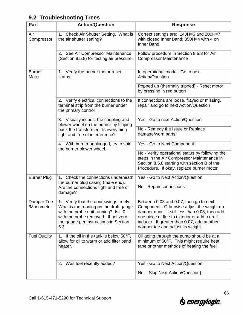
9.2 Troubleshooting Trees Part Action/Question Response
Air Compressor
1. Check Air Shutter Setting. What is the air shutter setting?
Correct settings are: 140H=5 and 200H=7 with closed Inner Band; 350H=4 with 4 on Inner Band.
2. See Air Compressor Maintenance (Section 8.5.8) for testing air pressure.
Follow procedure in Section 8.5.8 for Air Compressor Maintenance
Burner Motor
1. Verify the burner motor reset status.
In operational mode - Go to next Action/Question
Popped up (thermally tripped) - Reset motor by pressing in red button
2. Verify electrical connections to the terminal strip from the burner under the primary control
If connections are loose, frayed or missing, repair and go to next Action/Question
3. Visually inspect the coupling and blower wheel on the burner by flipping back the transformer. Is everything tight and free of interference?
Yes - Go to next Action/Question
No - Remedy the Issue or Replace damage/worn parts
4. With burner unplugged, try to spin the burner blower wheel.
Yes - Go to Next Component
No - Verify operational status by following the steps in the Air Compressor Maintenance in Section 8.5.8 starting with section B of the Procedure. If okay, replace burner motor
Burner Plug 1. Check the connections underneath the burner plug casing (male end). Are the connections tight and free of damage?
Yes - Go to Next Action/Question
No - Repair connections
Damper Tee /Manometer
1. Verify that the door swings freely. What is the reading on the draft gauge with the probe unit running? Is it 0 with the probe removed. If not zero the gauge per instructions in Section 5.3.
Between 0.03 and 0.07, then go to next Component. Otherwise adjust the weight on damper door. If still less than 0.03, then add one piece of flue to exterior or add a draft inducer. If greater than 0.07, add another damper tee and adjust its weight.
Fuel Quality 1. If the oil in the tank is below 50°F, allow for oil to warm or add filter band heater.
Oil going through the pump should be at a minimum of 50°F. This might require heat tape or other methods of heating the fuel
2. Was fuel recently added? Yes - Go to Next Action/Question
No - {Skip Next Action/Question}
66
Call 1-615-471-5290 for Technical Support
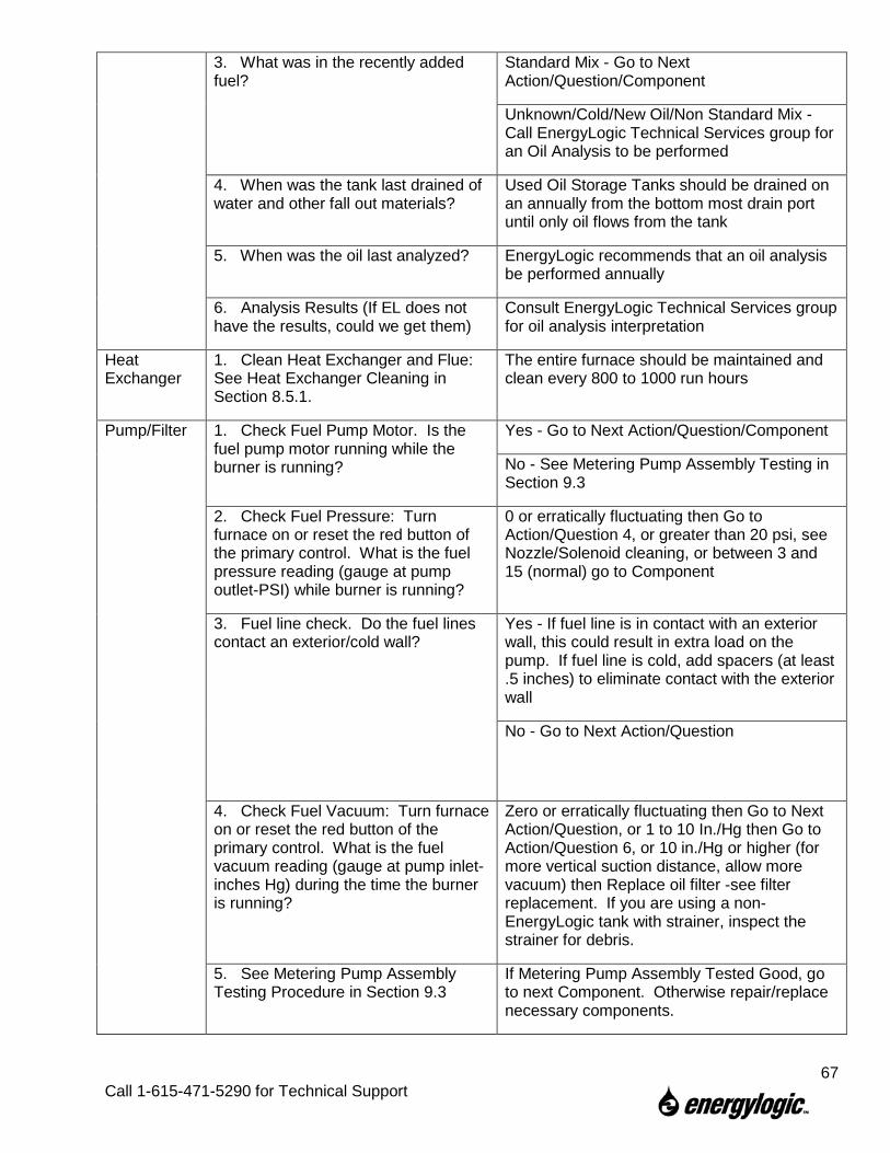
3. What was in the recently added fuel?
Standard Mix - Go to Next Action/Question/Component
Unknown/Cold/New Oil/Non Standard Mix - Call EnergyLogic Technical Services group for an Oil Analysis to be performed
4. When was the tank last drained of water and other fall out materials?
Used Oil Storage Tanks should be drained on an annually from the bottom most drain port until only oil flows from the tank
5. When was the oil last analyzed? EnergyLogic recommends that an oil analysis be performed annually
6. Analysis Results (If EL does not have the results, could we get them)
Consult EnergyLogic Technical Services group for oil analysis interpretation
Heat Exchanger
1. Clean Heat Exchanger and Flue: See Heat Exchanger Cleaning in Section 8.5.1.
The entire furnace should be maintained and clean every 800 to 1000 run hours
Pump/Filter 1. Check Fuel Pump Motor. Is the fuel pump motor running while the burner is running?
Yes - Go to Next Action/Question/Component
No - See Metering Pump Assembly Testing in Section 9.3
2. Check Fuel Pressure: Turn furnace on or reset the red button of the primary control. What is the fuel pressure reading (gauge at pump outlet-PSI) while burner is running?
0 or erratically fluctuating then Go to Action/Question 4, or greater than 20 psi, see Nozzle/Solenoid cleaning, or between 3 and 15 (normal) go to Component
3. Fuel line check. Do the fuel lines contact an exterior/cold wall?
Yes - If fuel line is in contact with an exterior wall, this could result in extra load on the pump. If fuel line is cold, add spacers (at least .5 inches) to eliminate contact with the exterior wall
No - Go to Next Action/Question
4. Check Fuel Vacuum: Turn furnace on or reset the red button of the primary control. What is the fuel vacuum reading (gauge at pump inlet-inches Hg) during the time the burner is running?
Zero or erratically fluctuating then Go to Next Action/Question, or 1 to 10 In./Hg then Go to Action/Question 6, or 10 in./Hg or higher (for more vertical suction distance, allow more vacuum) then Replace oil filter -see filter replacement. If you are using a non-EnergyLogic tank with strainer, inspect the strainer for debris.
5. See Metering Pump Assembly Testing Procedure in Section 9.3
If Metering Pump Assembly Tested Good, go to next Component. Otherwise repair/replace necessary components.
67
Call 1-615-471-5290 for Technical Support
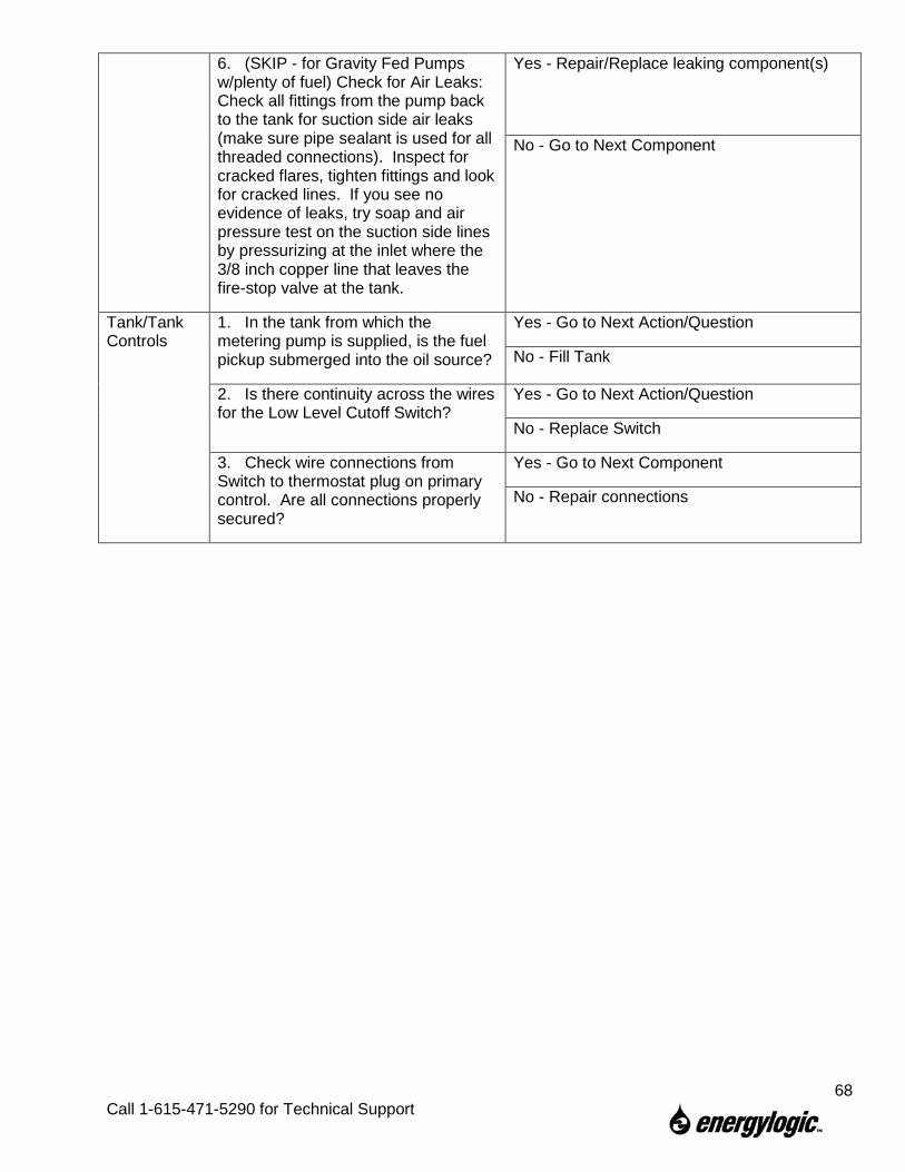
6. (SKIP - for Gravity Fed Pumps w/plenty of fuel) Check for Air Leaks: Check all fittings from the pump back to the tank for suction side air leaks (make sure pipe sealant is used for all threaded connections). Inspect for cracked flares, tighten fittings and look for cracked lines. If you see no evidence of leaks, try soap and air pressure test on the suction side lines by pressurizing at the inlet where the 3/8 inch copper line that leaves the fire-stop valve at the tank.
Yes - Repair/Replace leaking component(s)
No - Go to Next Component
Tank/Tank Controls
1. In the tank from which the metering pump is supplied, is the fuel pickup submerged into the oil source?
Yes - Go to Next Action/Question
No - Fill Tank
2. Is there continuity across the wires for the Low Level Cutoff Switch?
Yes - Go to Next Action/Question
No - Replace Switch
3. Check wire connections from Switch to thermostat plug on primary control. Are all connections properly secured?
Yes - Go to Next Component
No - Repair connections
68
Call 1-615-471-5290 for Technical Support
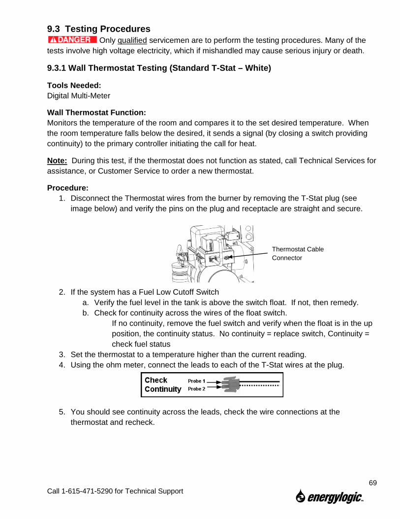
9.3 Testing Procedures Only qualified servicemen are to perform the testing procedures. Many of the
tests involve high voltage electricity, which if mishandled may cause serious injury or death.
9.3.1 Wall Thermostat Testing (Standard T-Stat – White)
Tools Needed: Digital Multi-Meter
Wall Thermostat Function: Monitors the temperature of the room and compares it to the set desired temperature. When the room temperature falls below the desired, it sends a signal (by closing a switch providing continuity) to the primary controller initiating the call for heat.
Note: During this test, if the thermostat does not function as stated, call Technical Services for assistance, or Customer Service to order a new thermostat.
Procedure: 1. Disconnect the Thermostat wires from the burner by removing the T-Stat plug (see
image below) and verify the pins on the plug and receptacle are straight and secure.
2. If the system has a Fuel Low Cutoff Switch a. Verify the fuel level in the tank is above the switch float. If not, then remedy. b. Check for continuity across the wires of the float switch.
If no continuity, remove the fuel switch and verify when the float is in the up position, the continuity status. No continuity = replace switch, Continuity = check fuel status
3. Set the thermostat to a temperature higher than the current reading. 4. Using the ohm meter, connect the leads to each of the T-Stat wires at the plug.
5. You should see continuity across the leads, check the wire connections at the thermostat and recheck.
Thermostat Cable Connector
69
Call 1-615-471-5290 for Technical Support
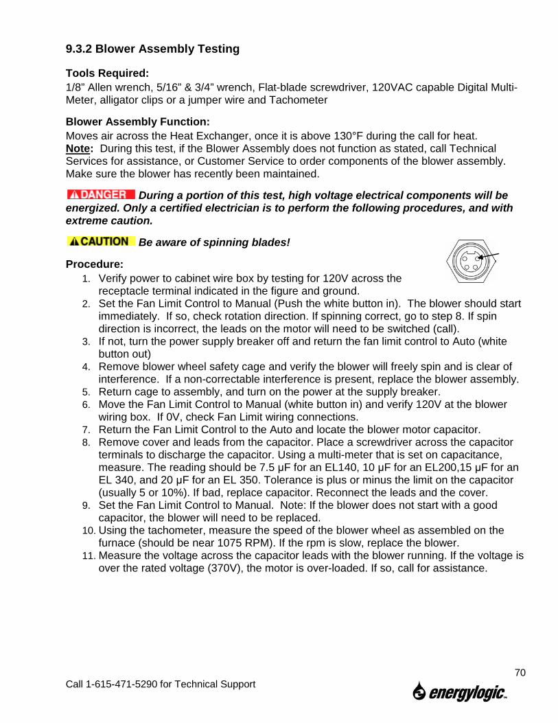
9.3.2 Blower Assembly Testing
Tools Required: 1/8” Allen wrench, 5/16” & 3/4” wrench, Flat-blade screwdriver, 120VAC capable Digital Multi-Meter, alligator clips or a jumper wire and Tachometer
Blower Assembly Function: Moves air across the Heat Exchanger, once it is above 130°F during the call for heat. Note: During this test, if the Blower Assembly does not function as stated, call Technical Services for assistance, or Customer Service to order components of the blower assembly. Make sure the blower has recently been maintained.
During a portion of this test, high voltage electrical components will be energized. Only a certified electrician is to perform the following procedures, and with extreme caution.
Be aware of spinning blades!
Procedure: 1. Verify power to cabinet wire box by testing for 120V across the
receptacle terminal indicated in the figure and ground. 2. Set the Fan Limit Control to Manual (Push the white button in). The blower should start
immediately. If so, check rotation direction. If spinning correct, go to step 8. If spin direction is incorrect, the leads on the motor will need to be switched (call).
3. If not, turn the power supply breaker off and return the fan limit control to Auto (white button out)
4. Remove blower wheel safety cage and verify the blower will freely spin and is clear of interference. If a non-correctable interference is present, replace the blower assembly.
5. Return cage to assembly, and turn on the power at the supply breaker. 6. Move the Fan Limit Control to Manual (white button in) and verify 120V at the blower
wiring box. If 0V, check Fan Limit wiring connections. 7. Return the Fan Limit Control to the Auto and locate the blower motor capacitor. 8. Remove cover and leads from the capacitor. Place a screwdriver across the capacitor
terminals to discharge the capacitor. Using a multi-meter that is set on capacitance, measure. The reading should be 7.5 μF for an EL140, 10 μF for an EL200,15 μF for an EL 340, and 20 μF for an EL 350. Tolerance is plus or minus the limit on the capacitor (usually 5 or 10%). If bad, replace capacitor. Reconnect the leads and the cover.
9. Set the Fan Limit Control to Manual. Note: If the blower does not start with a good capacitor, the blower will need to be replaced.
10. Using the tachometer, measure the speed of the blower wheel as assembled on the furnace (should be near 1075 RPM). If the rpm is slow, replace the blower.
11. Measure the voltage across the capacitor leads with the blower running. If the voltage is over the rated voltage (370V), the motor is over-loaded. If so, call for assistance.
70
Call 1-615-471-5290 for Technical Support
9.3.3 Cad Cell Testing
Tools Required: Flat-blade screwdriver, 120VAC capable Digital Multi-Meter (Ohms)
Cad Cell Function: The Cad Cell senses the flame via a resistance measurement, so the primary controller will continue to power the burner during the call for heat. The normal flame sensing range is less than 1600 ohms. With a reading greater than 1600 ohms, the primary controller does not recognize that a flame is present and will stop the burner as a safety precaution. Note: During this test, if the Cad Cell does not function as stated, call Technical Services for assistance, or Customer Service to order a new Cad Cell.
Procedure: 1. Unplug the burner plug from its receptacle. 2. Loosen or remove two ignition transformer screws. The cad cell is located on the
underside of the ignition transformer. Lift the ignition transformer and inspect the yellow cad cell leads for cuts or breaks.
3. Inspect the cad cell for signs of overheating, such as melted plastic or coating of soot. Clean or replace if you see any of these signs.
4. Gently wipe dust off the cad cell lens with a soft clean cloth (DO NOT use solvents on lens).
5. Set your multi-meter to the 100 ohm or 1K ohm range. 6. On the primary control, use the multi-meter to check across the “F” terminals.
a. The reading should be very high in the dark (30K ohms+ with ignition transformer closed) and very low in light (below 1600 ohms with ignition transformer lifted open).
7. Return the Transformer to its operating position and plug in the burner.
71
Call 1-615-471-5290 for Technical Support
9.3.4 Metering Pump Assembly Testing
Tools Required: 1/8” Allen wrench, 3/4” wrench, Flat-blade screwdriver, 120VAC capable Digital Multi-Meter, alligator clips or a jumper wire, Tachometer, stop watch and a graduated cylinder (ounce or milliliter).
Metering Pump Assembly Function: Pumps fuel from the tank to the preheater and burner during the call for heat (given the preheater is up to temperature) Note: During this test, if the Pump Assembly does not function as stated, call Technical Services for assistance, or Customer Service to order service parts.
During a portion of this test, high voltage electrical components will be energized. Only a certified electrician is to perform the following procedures, and with extreme caution.
Procedure: 1. Remove the pump assembly cover. 2. Inspect the coupler for damage or wear and make sure the set screws are tight and
positioned on the flats of the two shafts. If worn or damaged, replace. 3. Inspect the condition of, and rotate by hand, the shafts (pump and gear box). If worn or
damaged, replace. 4. Jumper the T-T terminals, as soon as you hear the burner start, jumper the F-F
terminals. 5. Use Caution when approaching the pump assembly, rotating parts will be
in operation. 6. Chattering from the gear box usually means damaged gearing. If chattering is heard or
felt, replace the gear box. 7. Close the ball valve at the bottom of the preheater. 8. Using a multi-meter, verify the voltage across the wires going to the pump motor, should
be around 115V AC. a. If voltage is not present, check the wires from the pump conduit to the wiring box and
in the primary control to ensure a secure fit and connections are proper (refer to wiring diagram for wire location and colors).
b. If voltage is present, but the motor does not function i. Remove jumper terminals from the T-T and F-F terminals. ii. Unhook the pink wire from the pump motor capacitor and hook it into the conduit
wire feeding the black wire going to the capacitor. iii. Jumper the primary as in Step 5.
1. If the motor runs, the capacitor is bad and must be replaced. 2. If the motor does not run, remove jumpers from the primary. 3. Remove the coupler from the pump assembly, and jumper the primary as in
Step 5 a. If the motor runs
i. Remove jumpers and test with capacitor. 1. If the motor runs with the capacitor, then the pump is seized and
should be replaced. 2. If motor does not run, replace capacitor.
72
Call 1-615-471-5290 for Technical Support
b. If motor does not run, replace motor. 9. With pump operating and preheater ball valve closed, verify that the pump outlet
pressure is around 60 psi (pump is now in bypass).
Speed testing with a tachometer 10. Test pump shaft speed per tachometer instruction and compare to values found in the
table under step 4.
Perform a suction test on system 11. Close fire stop valve and push down on the stem. Or, close ball valve. 12. Run pump until the vacuum gauge reads 15 in/Hg (should quickly reach), and stop
pump. 13. Cap the discharge side of the pump and note the vacuum gauge reading. 14. Wait 30 minutes. 15. Vacuum gauge reading should be the same as noted in step 14.
a. If not, check fittings and connections and retest, looking for signs of vacuum leaks.
Flow test 16. Disconnect the 3/16” copper line from the inlet of the solenoid valve at the top of the
preheater (you will use this tube to catch oil coming from the preheater.). 17. Have the graduated cylinder located so as to catch oil from the tube in step 17.
18. Start timing once the burner turns on by applying jumpers to the T & F terminals. 19. Allow to run for 120 seconds (2 minutes) and remove jumpers. 20. Fluid levels should be near the listed values in the following table.
ModelListed Flow Rates [gph]
Flow [oz/120 seconds]
Flow [ml/120 seconds]
140 1.0 4.3 126.2200 1.4 6.0 176.7350 2.5 10.7 315.5
73
Call 1-615-471-5290 for Technical Support
9.3.5 Preheater and Nozzle PTC Testing Procedure
Tools Required: 1/4”, 5/16” wrenches, alligator clips or jumper wire, 120 VAC capable Digital Multi-Meter DMM, temperature probe, or the TPI combustion analyzer with a type K thermocouple attached.
Preheater/Nozzle PTC Function: Heats the fuel to a temperature over 120°F for proper combustion. There are standby PTCs in the Preheater and the Nozzle that are energized whenever there is power to the burner in order to keep the fuel warm for immediate start up. When the burner is firing, there are extra run PTCs in the Preheater that energize to heat the fuel as it flows to the nozzle. Note: During this test, if the preheater does not function as stated, call Technical Services for assistance, or Customer Service to order a new preheater.
The preheaters are on at all times, making the nozzle block and external preheater assembly very hot to the touch.
Make sure the Preheater has recently been maintained. Neglect will negatively affect the results of testing
During a portion of this test, high voltage electrical components will be energized. Only a certified electrician is to perform the following procedures, and with extreme caution.
Procedure: 1. With the burner unplugged, verify the pins at the preheater plug and receptacle are
straight and secure. 2. Check the 8 Amp fuse (refer to figure below). If the fuse is blown, there is a high
probability that at least one of the run PTCs has shorted out. 3. Remove the wall thermostat connector from the side of the primary control and/or any
jumpers across the T-T terminals.
4. Disconnect the preheater plug. Allow the preheater to cool, and check the following with the digital multimeter:
a. Verify that the circuit between the two thermostat pins is open.
b. Verify that there is a resistance of 100-1000 ohms between the standby power and neutral pins.
c. Verify that there is a resistance of 100-1000 ohms between the run power and neutral pins.
If any of these tests fail, the preheater will need to be replaced.
Thermostat Cable Connector
Burner Plug
8 Amp Run Fuse
Preheater Plug
Wide Key at Top
Standby Heater - Neutral
Standby Heater – 115V
Preheater Thermostat
Run Heaters – 115V
Run Heaters - Neutral
(Center Pin Not Used)
Preheater Plug
74
Call 1-615-471-5290 for Technical Support
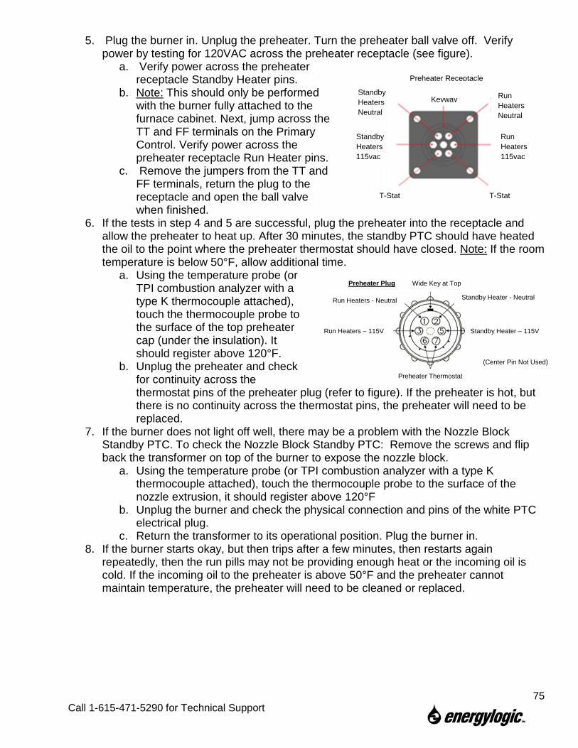
5. Plug the burner in. Unplug the preheater. Turn the preheater ball valve off. Verify power by testing for 120VAC across the preheater receptacle (see figure).
a. Verify power across the preheater receptacle Standby Heater pins.
b. Note: This should only be performed with the burner fully attached to the furnace cabinet. Next, jump across the TT and FF terminals on the Primary Control. Verify power across the preheater receptacle Run Heater pins.
c. Remove the jumpers from the TT and FF terminals, return the plug to the receptacle and open the ball valve when finished.
6. If the tests in step 4 and 5 are successful, plug the preheater into the receptacle and allow the preheater to heat up. After 30 minutes, the standby PTC should have heated the oil to the point where the preheater thermostat should have closed. Note: If the room temperature is below 50°F, allow additional time.
a. Using the temperature probe (or TPI combustion analyzer with a type K thermocouple attached), touch the thermocouple probe to the surface of the top preheater cap (under the insulation). It should register above 120°F.
b. Unplug the preheater and check for continuity across the thermostat pins of the preheater plug (refer to figure). If the preheater is hot, but there is no continuity across the thermostat pins, the preheater will need to be replaced.
7. If the burner does not light off well, there may be a problem with the Nozzle Block Standby PTC. To check the Nozzle Block Standby PTC: Remove the screws and flip back the transformer on top of the burner to expose the nozzle block.
a. Using the temperature probe (or TPI combustion analyzer with a type K thermocouple attached), touch the thermocouple probe to the surface of the nozzle extrusion, it should register above 120°F
b. Unplug the burner and check the physical connection and pins of the white PTC electrical plug.
c. Return the transformer to its operational position. Plug the burner in. 8. If the burner starts okay, but then trips after a few minutes, then restarts again
repeatedly, then the run pills may not be providing enough heat or the incoming oil is cold. If the incoming oil to the preheater is above 50°F and the preheater cannot maintain temperature, the preheater will need to be cleaned or replaced.
Preheater Receptacle
Keyway Run Heaters Neutral
Run Heaters 115vac
T-Stat T-Stat
Standby Heaters 115vac
Standby Heaters Neutral
Wide Key at Top
Standby Heater - Neutral
Standby Heater – 115V
Preheater Thermostat
Run Heaters – 115V
Run Heaters - Neutral
(Center Pin Not Used)
Preheater Plug
75
Call 1-615-471-5290 for Technical Support
9.3.6 Primary Control Testing
Tools Required: Flat-blade screwdriver, alligator clip or piece of jumper wire.
Primary Controller Function: Processes the call for heat and distributes power to the necessary components in order to operate the furnace or boiler. During the startup and heating cycle, the primary controller looks for a flame to insure that there is combustion, and shuts down the burner if there is no flame.
Note: During this test, if the Primary Controller does not function as stated, call Technical Services for assistance, or Customer Service to order a new Controller. Note: With the T-T terminals jumped, if the Burner does not operate, verify that the primary is sending power by checking the voltage across the orange and white terminals beneath the primary control.
During a portion of this test, high voltage electrical components will be energized. Only a certified electrician is to perform the following procedures, and with extreme caution.
Procedure: 1. Set the Wall Thermostat to a temperature setting lower than current ambient
temperature. 2. Disconnect one of the wires going to the F-F terminals on the primary
Testing the Limited Recycle Mode function of the Primary Control 3. Use the alligator clip or jumper wire to connect the T-T terminals
a. Burner should run for –several seconds, resulting in reset. b. –If this happens, the primary control is working properly.
i. If the burner does not operate, unplug the burner and check the connections in the burner wiring box. Then, repeat the testing. If the burner still does not operate, replace the primary control.
ii. Go to step 7 if complete, else go to continue to step 4.
Testing the Recycle function of the Primary Control 4. Use the alligator clip or jumper wire to connect the T-T terminals. 5. When burner starts, use alligator clip or jumper wire to connect the F-F terminals and
allow to run for 1 minute. 6. Remove jumper from F-F terminals
a. Burner should run for several seconds, resulting in reset. If this happens, the primary control is working properly.
b. If the burner does not operate, unplug the burner and check the connections in the burner wiring box. Then, repeat the testing. If the burner still does not operate, replace the primary control.
Completing the Test 7. Reconnect the wire removed in Step 2. 8. Return the Wall Thermostat setting to an appropriate temperature.
76
Call 1-615-471-5290 for Technical Support
9.3.7 Solenoid Valve Testing
Tools Required: 7/16” wrench, Flat-blade screwdriver, 120VAC capable Digital Multi-Meter and alligator clips or jumper wires.
Solenoid Valve Function: Blocks flow of the fuel from the preheater to the nozzle block when burner is not operating, and allows for flow during burner operation. The valve is a Normally Closed Valve. Note: During this test, if the Solenoid does not function as stated, call Technical Services for assistance, or Customer Service to order a new Solenoid Valve.
Make sure the Solenoid has recently been maintained. Neglect will negatively affect the results of testing.
During a portion of this test, high voltage electrical components will be energized. Only a certified electrician is to perform the following procedures, and with extreme caution.
Procedure: 1. Unplug the burner plug from its receptacle. Unplug preheater. 2. Remove the primary control cover plate, allowing access to the terminal strip under
controller. 3. Find the solenoid valve wires, purple and white of the same gauge, and remove from
terminal strip. 4. Using a multi-meter, test for continuity across the solenoid wires. There should be
continuity across wires. 5. Leaving the purple and white wires disconnected, loosely replace the primary cover. 6. Remove copper tubing from between the solenoid and the nozzle (have cup or
disposable towel ready to catch oil). 7. Wear Safety Glasses for the following steps! 8. Plug in the burner and jumper the T-T terminals. 9. After the burner starts, jumper the F-F terminals. 10. Holding the cup near the open end of the solenoid valve, observe to see if the valve
leaks while the burner is running. The valve should not leak during operation. 11. Remove the T-T and F-F terminal jumpers. 12. Unplug the burner plug from its receptacle. Reconnect the solenoid to the terminal strip.
Plug the burner back in. 13. Apply the jumpers as in steps 9 and 10. 14. The solenoid should open and oil should flow out of the solenoid.
a. If oil does not flow, verify 105-120VAC is supplied to the solenoid from the terminal strip.
15. Remove the jumpers from the T-T terminals, then the F-F terminals and unplug the burner.
16. Return the wires, primary, copper and preheater plug to their operational positions. 17. Plug in the burner.
77
Call 1-615-471-5290 for Technical Support
9.3.8 Top Suction Kit Testing
Tools Required: Adjustable wrenches, alligator clips
Top Suction Kit Function: Save time/money and increase reliability when delivering fuel from the top of various types of tanks. An EnergyLogic Top Suction Kit combines fuel pick-up with a foot valve and a low fuel cut off switch. The fuel pick-up line has a copper tube, increasing reliability of the fuel delivery. An EnergyLogic Low Fuel Cutoff Switch is provided to interrupt operation when the fuel level in the tank is low, reducing the chance of introducing air into the fuel lines.
Note: During this test, if the Top Suction Kit does not function as stated, call Technical Services for assistance. Note: To check low fuel cut-off function, see Thermostat Testing (Section 9.3.1).
Procedure : 1. Run the pump vacuum check (Section 9.3.4, steps 12 –16) and make sure that you
have proper and tight flare connections. If there is a leak, repair it or call for assistance. 2. Disconnect the 3/8” copper tube at union above the tank. Disconnect wiring for low fuel
cut-off switch. 3. Remove the suction copper and foot valve from tank. 4. Clean the oil from the suction copper and foot valve thoroughly. 5. With the suction copper vertical (as it mounts in the tank), fill the tube with oil. Place a
clean paper towel under the foot valve. 6. Let the filled assembly set for 20 minutes. Inspect for oil leaks on the paper towel. 7. If there is evidence of a leak, and it can be located, repair if possible using thread
sealant. If repair is not possible, call for assistance or order replacement parts.
78
Call 1-615-471-5290 for Technical Support
9.3.9 Iron Core Transformer Testing
Tools Required: Flat-blade screwdriver, 120 VAC capable Digital Multi-Meter (must have mA AC capability) and alligator clips or a jumper wire.
Transformer Function: Transforms 120 Volts into a low ampere, high voltage (10,000 V) supply to the electrode. This provides the spark needed for combustion. Note: During this test, if the Transformer does not function as stated, call Technical Services for assistance, or Customer Service to order a service part.
EnergyLogic does not recommend the use of a screwdriver or any other conductor to contact the transformer springs other than the testing procedure below!
During a portion of this test, high voltage electrical components will be energized. Only a certified electrician is to perform the following procedures, and with extreme caution.
Procedure: 1. Unplug the preheater. 2. Use the screwdriver to loosen the primary control mounting cover and lift to allow
access to terminal strip underneath. 3. With the burner plugged in, jumper the T-T terminals to simulate a call for heat. When
the burner starts, jumper the F-F terminals on the primary control. 4. Find the Black wires coming from the transformer and cautiously check the voltage
across the terminals. Should read between 105 and 120 volts AC. a. If reading is not within range, call your electrician to rectify voltage issue. There
may be an issue with your local power company. 5. Remove jumpers from T-T and F-F terminals. 6. Unplug the burner plug from its receptacle. 7. Loosen or remove two ignition transformer screws. 8. Tilt back the transformer. 9. Verify that the springs are making contact with the electrode extensions by visually
aligning the springs with the extensions. If they are misaligned, reshape the springs to ensure good contact. If soot is present, clean with wire brush or emery cloth.
10. Use Caution when approaching the transformer springs! They will be energized with step 11.
11. Plug in the burner and replace the jumpers as in step 3. You will need to disconnect the yellow wires from the terminal strip to the cad cell for the burner to restart.
Using a digital multi-meter: 12. Using your digital multi-meter
a. Without an amp clamp (must have mA AC capability) i. Set the reading to amperes. ii. Test amperes from spring to spring. iii. Reading should be between 20mA and 26mA with a nominal of 23mA.
(transformer should be labeled)
79 Call 1-615-471-5290 for Technical Support
b. With an amp clamp (must have mA AC capability) i. With burner plug unplugged, run wire from spring to spring of the
transformer. ii. Plug in the burner and apply jumpers as in step 11. iii. Using the amp clamp around the wire, read the amperes.
1. Reading should be between 20mA and 26mA with a nominal of 23mA. (transformer should be labeled)
13. Remove jumpers from T-T and F-F terminals. 14. Unplug the burner plug from its receptacle. 15. Return the Transformer and Primary Controller to its operating position and plug in the burner.
80
Call 1-615-471-5290 for Technical Support
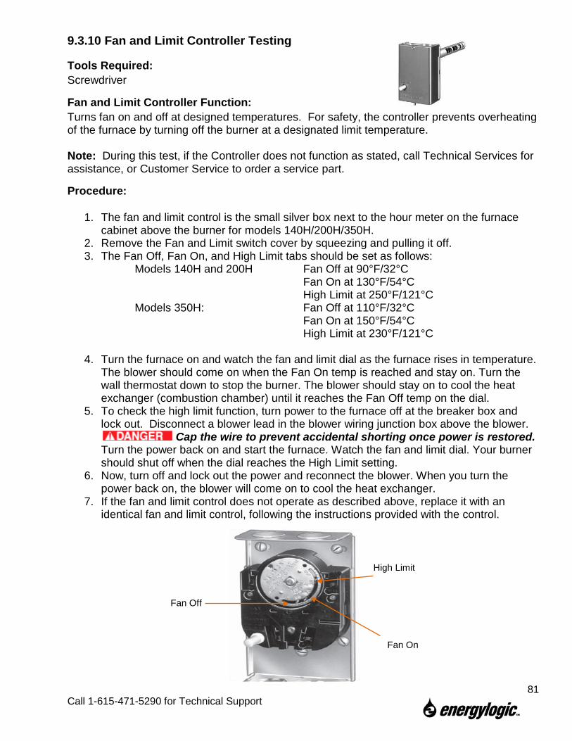
9.3.10 Fan and Limit Controller Testing
Tools Required: Screwdriver
Fan and Limit Controller Function: Turns fan on and off at designed temperatures. For safety, the controller prevents overheating of the furnace by turning off the burner at a designated limit temperature. Note: During this test, if the Controller does not function as stated, call Technical Services for assistance, or Customer Service to order a service part.
Procedure:
1. The fan and limit control is the small silver box next to the hour meter on the furnace cabinet above the burner for models 140H/200H/350H.
2. Remove the Fan and Limit switch cover by squeezing and pulling it off. 3. The Fan Off, Fan On, and High Limit tabs should be set as follows:
Models 140H and 200H Fan Off at 90°F/32°C Fan On at 130°F/54°C High Limit at 250°F/121°C
Models 350H: Fan Off at 110°F/32°C Fan On at 150°F/54°C High Limit at 230°F/121°C
4. Turn the furnace on and watch the fan and limit dial as the furnace rises in temperature. The blower should come on when the Fan On temp is reached and stay on. Turn the wall thermostat down to stop the burner. The blower should stay on to cool the heat exchanger (combustion chamber) until it reaches the Fan Off temp on the dial.
5. To check the high limit function, turn power to the furnace off at the breaker box and lock out. Disconnect a blower lead in the blower wiring junction box above the blower.
Cap the wire to prevent accidental shorting once power is restored. Turn the power back on and start the furnace. Watch the fan and limit dial. Your burner should shut off when the dial reaches the High Limit setting.
6. Now, turn off and lock out the power and reconnect the blower. When you turn the power back on, the blower will come on to cool the heat exchanger.
7. If the fan and limit control does not operate as described above, replace it with an identical fan and limit control, following the instructions provided with the control.
Fan Off
Fan On
High Limit
81
Call 1-615-471-5290 for Technical Support
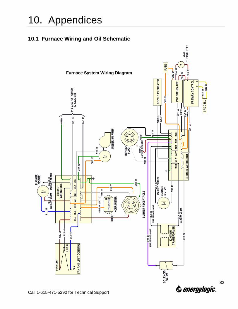
10. Appendices
10.1 Furnace Wiring and Oil Schematic
82
Call 1-615-471-5290 for Technical Support
Furnace System Wiring Diagram
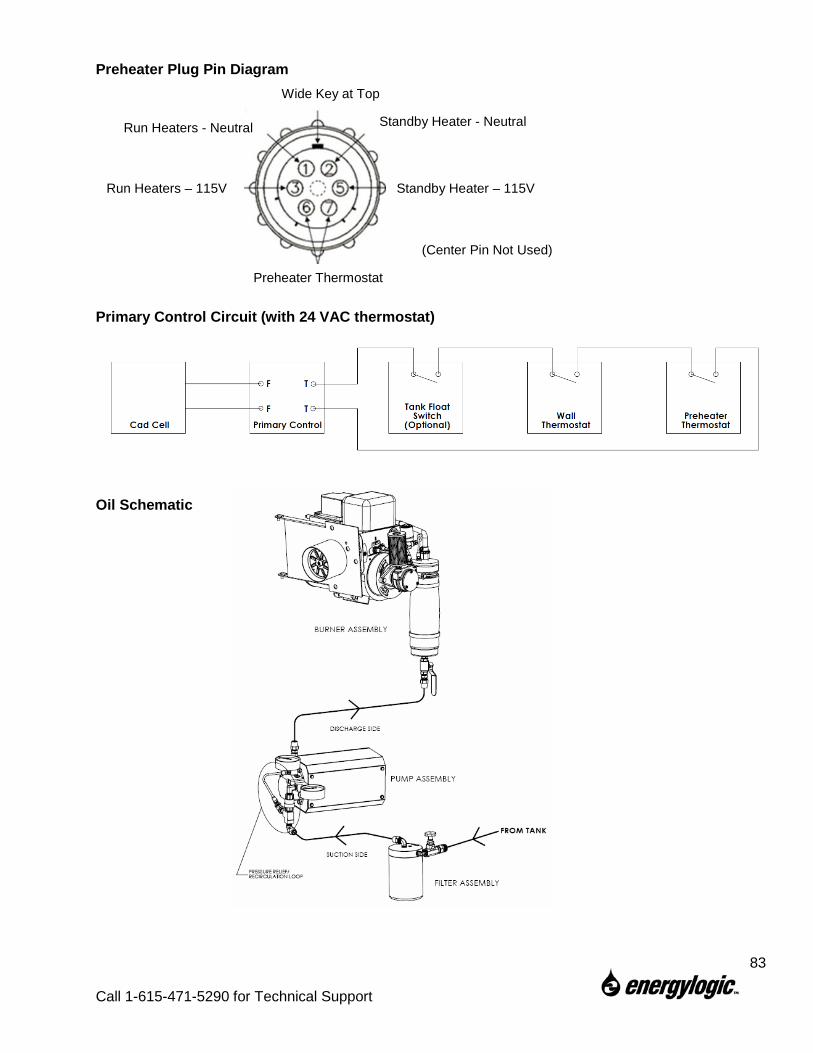
Preheater Plug Pin Diagram
Primary Control Circuit (with 24 VAC thermostat)
Oil Schematic
Wide Key at Top
Standby Heater - Neutral
Standby Heater – 115V
Preheater Thermostat
Run Heaters – 115V
Run Heaters - Neutral
(Center Pin Not Used)
83
Call 1-615-471-5290 for Technical Support
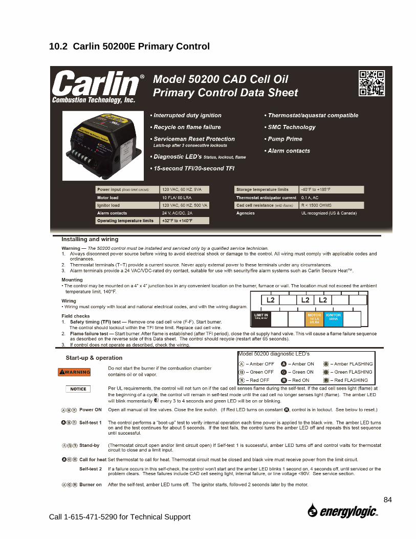
10.2 Carlin 50200E Primary Control
84
Call 1-615-471-5290 for Technical Support
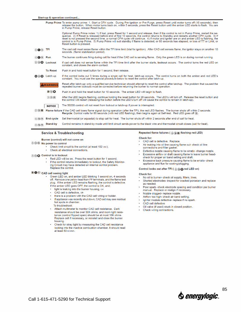
85
Call 1-615-471-5290 for Technical Support
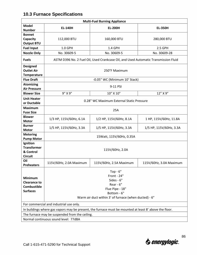
10.3 Furnace Specifications Multi-Fuel Burning Appliance
Model Number EL-140H EL-200H EL-350H
Bonnet Capacity Output BTU
112,000 BTU 160,000 BTU 280,000 BTU
Fuel Input 1.0 GPH 1.4 GPH 2.5 GPH Nozzle Only No. 30609-5 No. 30609-5 No. 30609-28
Fuels ASTM D396 No. 2 Fuel Oil, Used Crankcase Oil, and Used Automatic Transmission Fluid
Designed Outlet Air Temperature
250°F Maximum
Flue Draft -0.05" WC (Minimum 10’ Stack) Atomizing Air Pressure 9-11 PSI
Blower Size 9" X 9" 10" X 10" 12” X 9” Unit Heater or Ductable 0.28" WC Maximum External Static Pressure
Maximum Fuse Size 25A
Blower Motor 1/3 HP, 115V/60Hz, 6.1A 1/2 HP, 115V/60Hz, 8.1A 1 HP, 115V/60Hz, 11.8A
Burner Motor 1/5 HP, 115V/60Hz, 3.3A 1/5 HP, 115V/60Hz, 3.3A 1/5 HP, 115V/60Hz, 3.3A
Metering Pump Motor 15Watt, 115V/60Hz, 0.35A
Ignition Transformer & Control Circuit
115V/60Hz, 2.0A
Oil Preheaters 115V/60Hz, 2.0A Maximum 115V/60Hz, 2.5A Maximum 115V/60Hz, 3.0A Maximum
Minimum Clearance to Combustible Surfaces
Top - 6" Front - 24" Sides - 6" Rear - 6"
Flue Pipe - 18" Bottom - 6"
Warm air duct within 3' of furnace (when ducted) - 6"
For commercial and industrial use only. In buildings where gas vapors may be present, the furnace must be mounted at least 8’ above the floor. The furnace may be suspended from the ceiling. Normal continuous sound level: 77dBA
86
Call 1-615-471-5290 for Technical Support
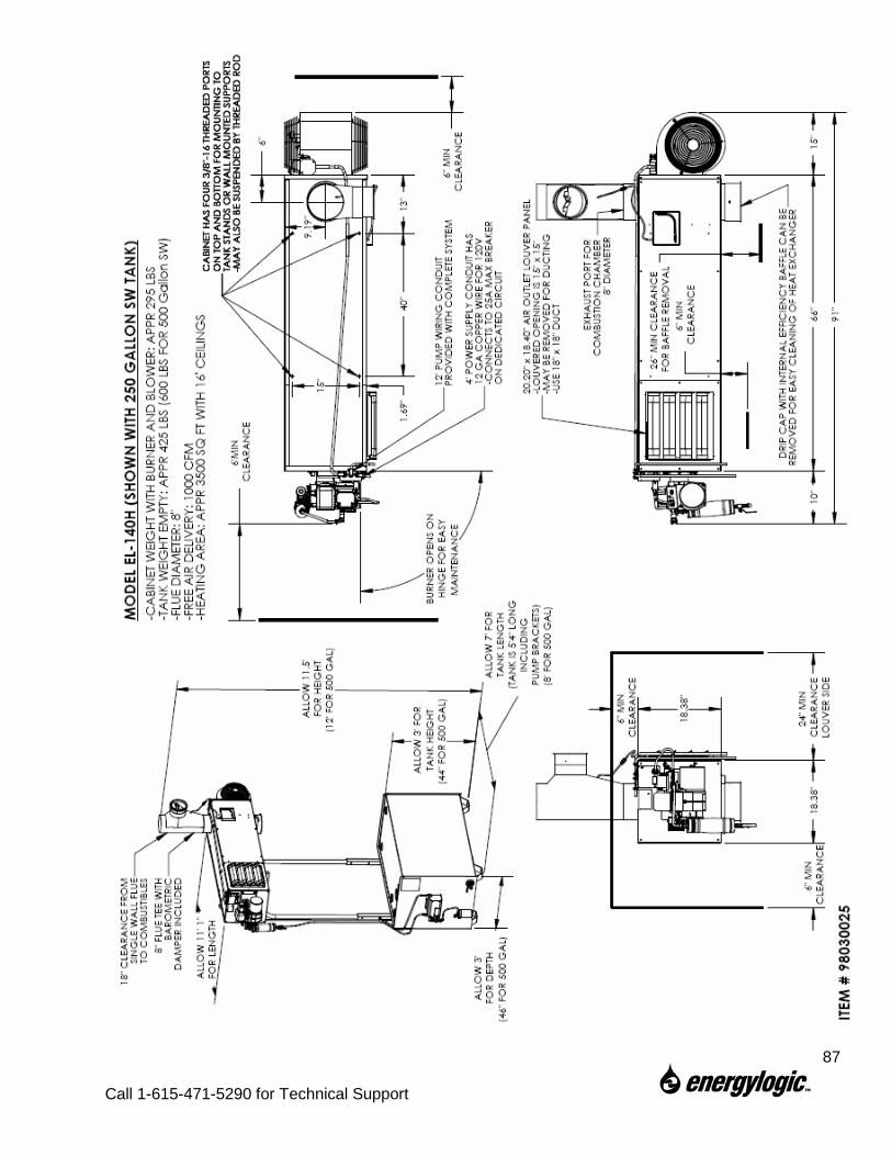
87
Call 1-615-471-5290 for Technical Support
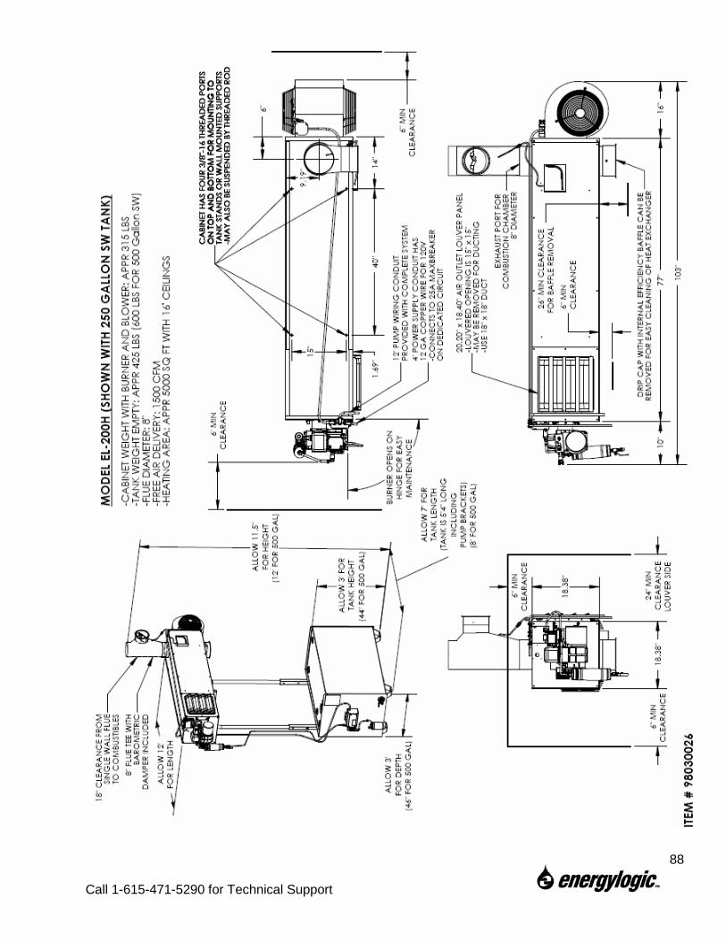
88
Call 1-615-471-5290 for Technical Support
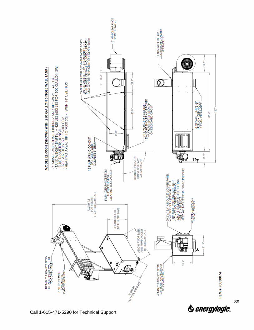
89
Call 1-615-471-5290 for Technical Support
10.4 Limited Warranty EnergyLogic, LLC, MANUFACTURER, warrants to the buyer that MANUFACTURER’s furnace be free from defect in material and workmanship according to the provisions and limitations set forth herein for a period of one (1) year from the Effective Date (as defined below) or 1,500 hours of operation, whichever occurs first. The buyer is responsible for registering the unit with the MANUFACTURER. If the unit is not registered, the buyer is responsible for maintaining proof of the purchase date of the unit. The warranty coverage period begins on the date (the “Effective Date”) of purchase, as established by the buyer, or otherwise on the date of manufacture as indicated by the serial number. No warranty claim examination shall commence until the unit is registered with the MANUFACTURER.
Non-consumables or parts that are not associated with a maintenance service interval because of normal wear shall be warranted for a period of one (1) years from the Effective Date or 1,500 hours of operation, whichever occurs first. A second year will be activated when the product is registered with the Manufacturer with in the first 30 days of receipt of the Product.
The heat exchanger chamber/combustion chamber shall be warranted for a period of ten (10) years from the Effective Date or 15,000 hours of operation, whichever occurs first. The Furnace Limited Warranty includes 100% of parts coverage for heat exchanger replacement during the first five (5) years from the Effective Date or 7,500 hours of operation, whichever occurs first, with prorated coverage (from the Effective Date) for the remainder of the ten (10) year term.
Parts (including heat exchangers) replaced during the original equipment warranty period as detailed herein shall carry either a one (1) year warranty from the date of purchase or the remainder of the factory warranty for the original equipment, whichever occurs last. In no event shall a part replaced under the original warranty carry a warranty that extends beyond one year from the expiration of the original factory warranty period.
Warranty Exclusions:
1. Consumable parts or any part that is associated with a normal maintenance interval because of normal wear and tear (filters, seals, gaskets, air compressor vanes, batteries, insulation, furnace cabinets).
2. Products or parts which are not maintained in accordance with the service frequency and methods described in the MANUFACTURER’S instructions furnished and / or available upon request from the buyer.
3. Parts and products that are not installed and operated according to MANUFACTURER’S instructions furnished and / or available upon request from the buyer.
4. Repairs made with parts or accessories which are not genuine EnergyLogic LLC or EnergyLogic LLC approved 5. Installations not in accordance with Manufacturers Installation Manual, UL, NFPA guidelines, federal, state, and local codes and regulations. 6. Labor or other costs incurred in troubleshooting, repair, removal, transportation, installation, service or handling of parts. 7. Claims, representation, or warranty made by any dealer, distributor, or other person that is inconsistent with or is more expansive than the provisions
provided herein. 8. Parts that are altered from original specifications of the MANUFACTURER or are damaged because of misuse, improper handling, storage, or use in
conjunction with other parts not authorized by MANUFACTURER. 9. Products that have been moved from the original installation site or that have been sold or exchanged to a person other than the original buyer. 10. Equipment or products installed outside of the continental U.S. or Canada. 11. Products or parts in which the serial number has been altered, defaced, or removed.
The buyer must assist the MANUFACTURER’S Technical Support group during over-the-phone problem diagnosis in order to help substantiate a warranty condition. A course of action will be determined by the MANUFACTURER if repair or replacement is deemed necessary.
MANUFACTURER’S liability under this warranty shall be limited to the repair or replacement of any part or parts that may prove to be defective under such normal operation and use, subject to MANUFACTURER’S examination and determination to its satisfaction that such part or parts are so defective.
Obtaining Warranty Service:
If the local Service Provider is unknown, contact EnergyLogic, LLC at 5901 Crossings Blvd, Antioch, TN 37013, or at 1-615-471-5290. A representative will assist you in locating the nearest authorized service provider or in verifying the warranty coverage. The Unit Registration identification number will be required. Please refer to our website at www.energylogic.com for more information.
In order for a warranty claim to be acknowledged by the MANUFACTURER, the buyer must be issued a Return Authorization (RA) number and the product must be Warranty Registered. After obtaining an RA number, the buyer must properly package the part to avoid damage during shipment with the RA number visible on the outside of the box. A credit card number must be provided in order for the replacement part to be shipped and the part must be returned within 30 days of receipt of the replacement part in order to avoid charges.
If MANUFACTURER determines that a problem with a product or part is not covered under the Limited Warranty, the buyer will be notified and informed of service alternatives available on a fee basis.
DISCLAIMER AND LIMITATION OF DAMAGES: THIS LIMITED WARRANTY IS EXPRESSLY IN LIEU OF ALL OTHER WARRANTIES, EXPRESSED OR IMPLIED, TO THE EXCLUSION OF ANY AND ALL OTHER WARRANTIES OR REPRESENTATIONS THAT MAY BE EXPRESSED OR IMPLIED BY ANY LITERATURE, PACKAGING, SAMPLES, MODELS, DATA OR PERSONS. MANUFACTURER DOES NOT ASSUME, NOR DO WE AUTHORIZE ANY EMPLOYEE, AGENT, OR OTHER PERSON TO ASSUME FOR US, ANY OTHER RESPONSIBILITY OR LIABILITY IN CONNECTION WITH THE SALE OF THE GOODS COVERED HEREBY. MANUFACTURER HEREBY DISCLAIMS ANY WARRANTY OF MERCHANTABILITY OR FITNESS FOR A PARTICULAR PURPOSE OR USE. MANUFACTURER’S MAXIMUM LIABILITY HEREUNDER SHALL NEVER EXCEED THE COST OF THE PRODUCT. MANUFACTURER IS NOT RESPONSIBLE FOR OR LIABLE FOR DIRECT, INDIRECT, SPECIAL, INCIDENTAL, CONSEQUENTIAL OR PUNITIVE DAMAGES RESULTING FROM THE USE OF THE GOODS COVERED HEREBY OR ANY BREACH OF WARRANTY OR UNDER ANY OTHER LEGAL THEORY, INCLUDING BUT NOT LIMITED TO CONTRACT, TORT, NEGLIGENCE, STRICT LIABILITY, LOST PROFITS OR GOODWILL, LOSS OF TIME, INCONVENIENCE, LOST FUEL, LOST SAVINGS, LABOR CHARGES OR OTHER INCIDENTAL OR CONSEQUENTIAL DAMAGES WITH RESPECT TO PERSONS, BUSINESS OR PROPERTY WHETHER AS A RESULT OF BREACH OF WARRANTY OR OTHERWISE. THIS WARRANTY IS LIMITED TO THE PRECISE TERMS SET FORTH ABOVE, AND PROVIDES EXCLUSIVE REMEDIES EXPRESSLY IN LIEU OF ALL OTHER REMEDIES.
90
Call 1-615-471-5290 for Technical Support