Embed Size (px)
Citation preview
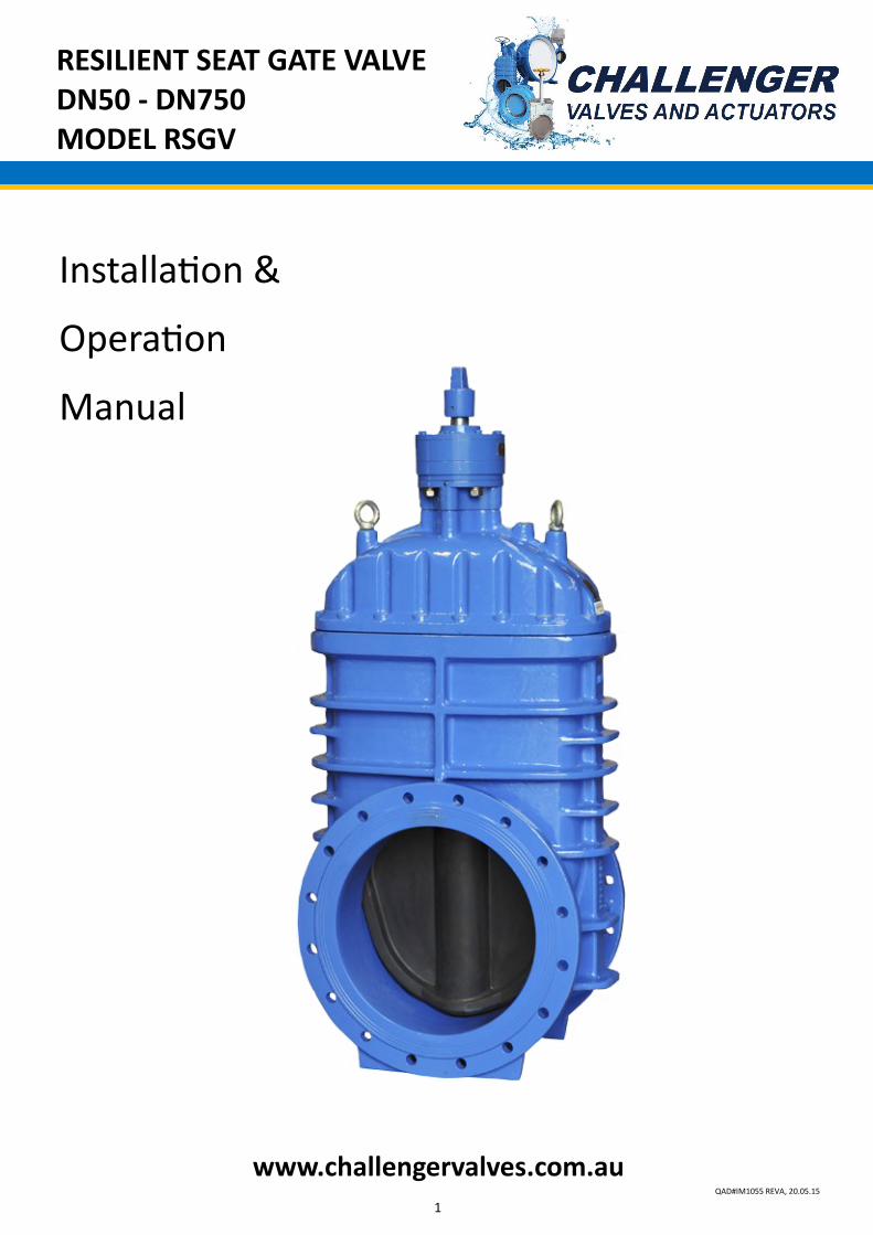
RESILIENT SEAT GATE VALVE DN50 - DN750 MODEL RSGV
1 QAD#IM1055 REVA, 20.05.15
www.challengervalves.com.au
Installation &
Operation
Manual
RESILIENT SEAT GATE VALVE DN50 - DN750 MODEL RSGV
2 QAD#IM1055 REVA, 20.05.15
Index
1. INTRODUCTION
1.1 General Application 3
1.2 Technical Data 3
1.3 Features 4
1.4 Operation 4
1.5 Design Constraints 4
2. PARTS LIST AND DIMENSIONS
2.1 DN50 to DN300 5
2.2 DN375 to DN400 6
2.3 DN450 to DN750 7
3. INSTALLATION, OPERATION AND MAINTENANCE
3.1 Preparation 8
3.2 Installation 8
3.3 Maintenance 8
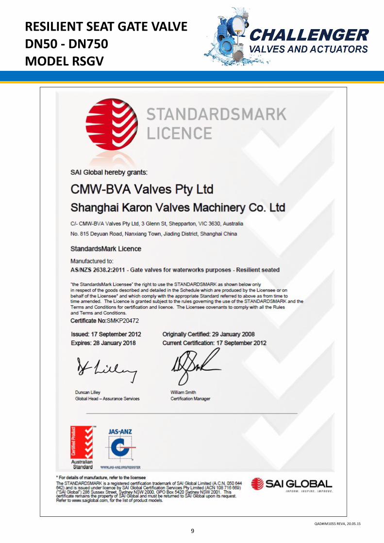
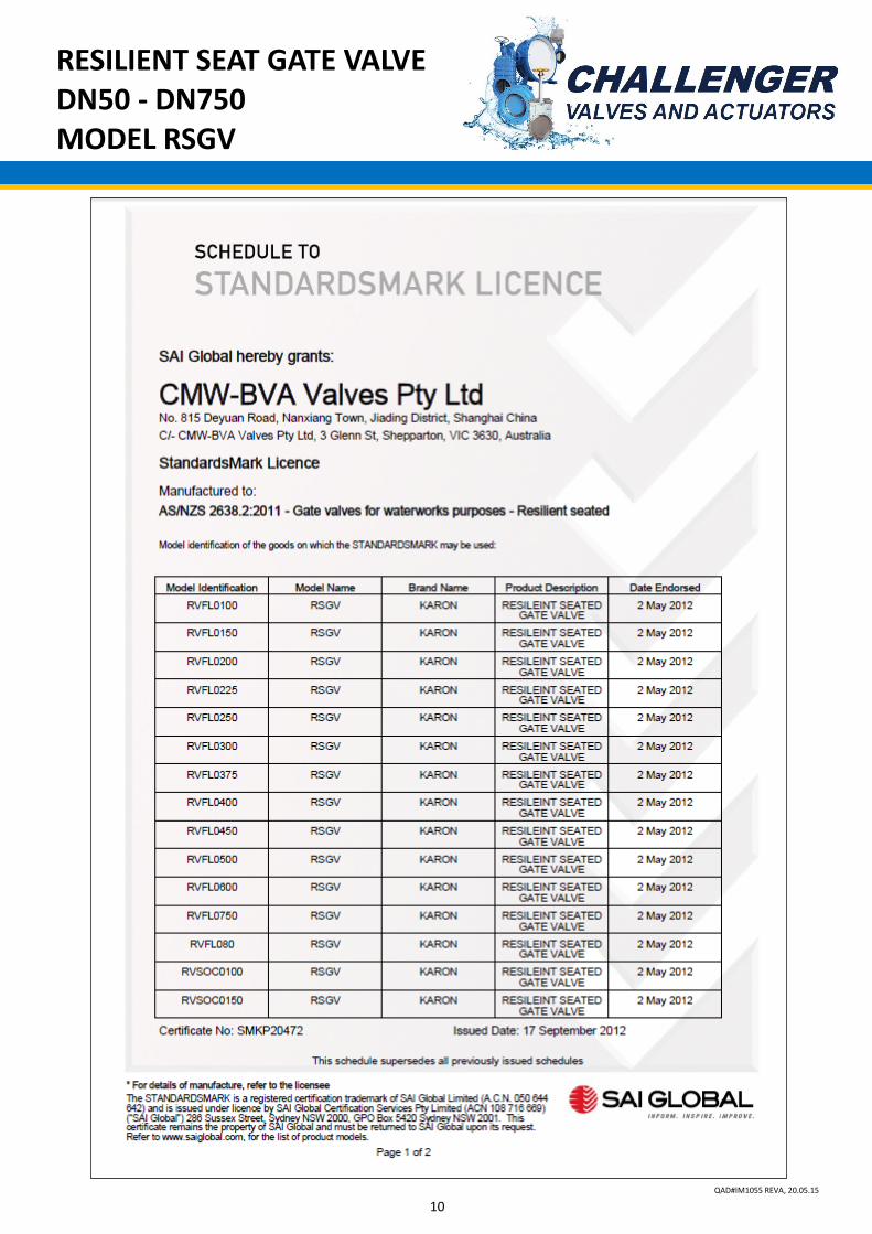
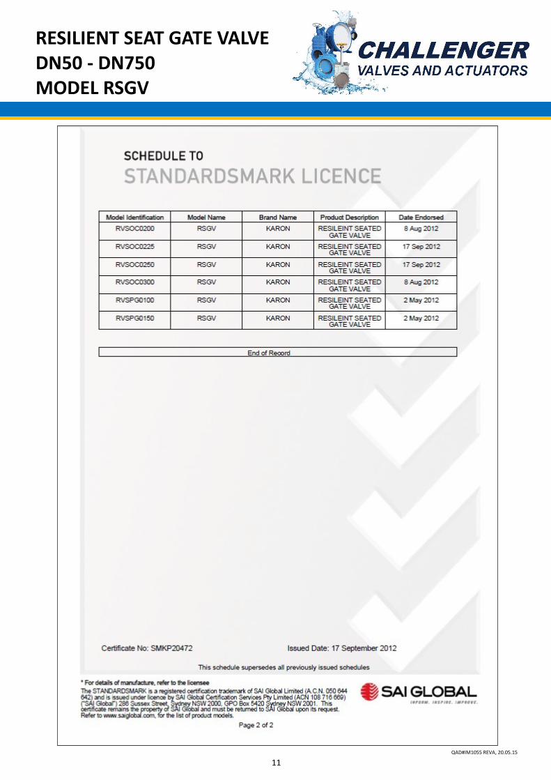
4. SIA GLOBAL Licence 9
RESILIENT SEAT GATE VALVE DN50 - DN750 MODEL RSGV
3 QAD#IM1055 REVA, 20.05.15
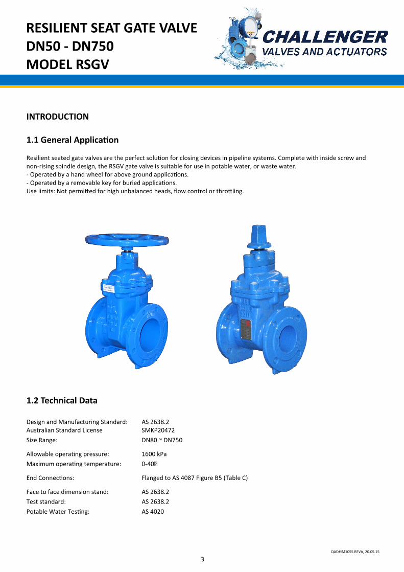
INTRODUCTION 1.1 General Application Resilient seated gate valves are the perfect solution for closing devices in pipeline systems. Complete with inside screw and non-rising spindle design, the RSGV gate valve is suitable for use in potable water, or waste water. - Operated by a hand wheel for above ground applications. - Operated by a removable key for buried applications. Use limits: Not permitted for high unbalanced heads, flow control or throttling.
1.2 Technical Data Design and Manufacturing Standard: AS 2638.2 Australian Standard License SMKP20472
Size Range: DN80 ~ DN750
Allowable operating pressure: 1600 kPa
Maximum operating temperature: 0-40℃
End Connections: Flanged to AS 4087 Figure B5 (Table C)
Face to face dimension stand: AS 2638.2
Test standard: AS 2638.2
Potable Water Testing: AS 4020
RESILIENT SEAT GATE VALVE DN50 - DN750 MODEL RSGV
4 QAD#IM1055 REVA, 20.05.15
1.4 Operation
The RSGV gate valve is designed and manufactured to close to completely, block flow, or open fully to allow maximum flow in
pipelines. It is suitable for use with potable water, raw water and low solids sewage up to 40ºC.
Minimum liquid temperature must be above freezing.
1.5 Design Constraints
Please consider the following points when selecting your valve:
- Consideration should be given at the design stage as to where valves will be located to give access for operation, adjustment,
maintenance and repair.
- If a valve is installed less than 6 diameters downstream of an elbow or tee etc., it will experience very high-localised velocities
that are far in excess of the average velocity. This high velocity will result in excessive turbulence within the valve and
variations in performance may be experienced, therefore installation in this area should be avoided.
- Valves must be provided with adequate support. Adjoining pipework must be supported to avoid the imposition of pipeline
strains on the body which may impair its performance.
- Heavy valves may need independent support or anchorage.
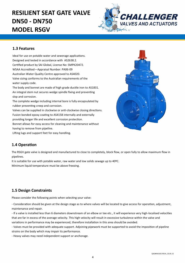
1.3 Features
Ideal for use on potable water and sewerage applications.
Designed and tested in accordance with AS2638.2.
Certified product by SAI Global, License No: SMPK20472.
WSAA Accredited—Appraisal Number: PA06-09
Australian Water Quality Centre approved to AS4020.
Valve sizing conforms to the Australian requirements of the
water supply code.
The body and bonnet are made of high grade ductile iron to AS1831.
An integral stem nut secures wedge spindle fixing and preventing
slop and corrosion.
The complete wedge including internal bore is fully encapsulated by
rubber preventing creep and corrosion.
Valves can be supplied in clockwise or anti-clockwise closing directions.
Fusion bonded epoxy coating to AS4158 internally and externally
providing longer life and excellent corrosion protection.
Bonnet allows for easy access for cleaning and maintenance without
having to remove from pipeline.
Lifting lugs and support feet for easy handling.
RESILIENT SEAT GATE VALVE DN50 - DN750 MODEL RSGV
5 QAD#IM1055 REVA, 20.05.15
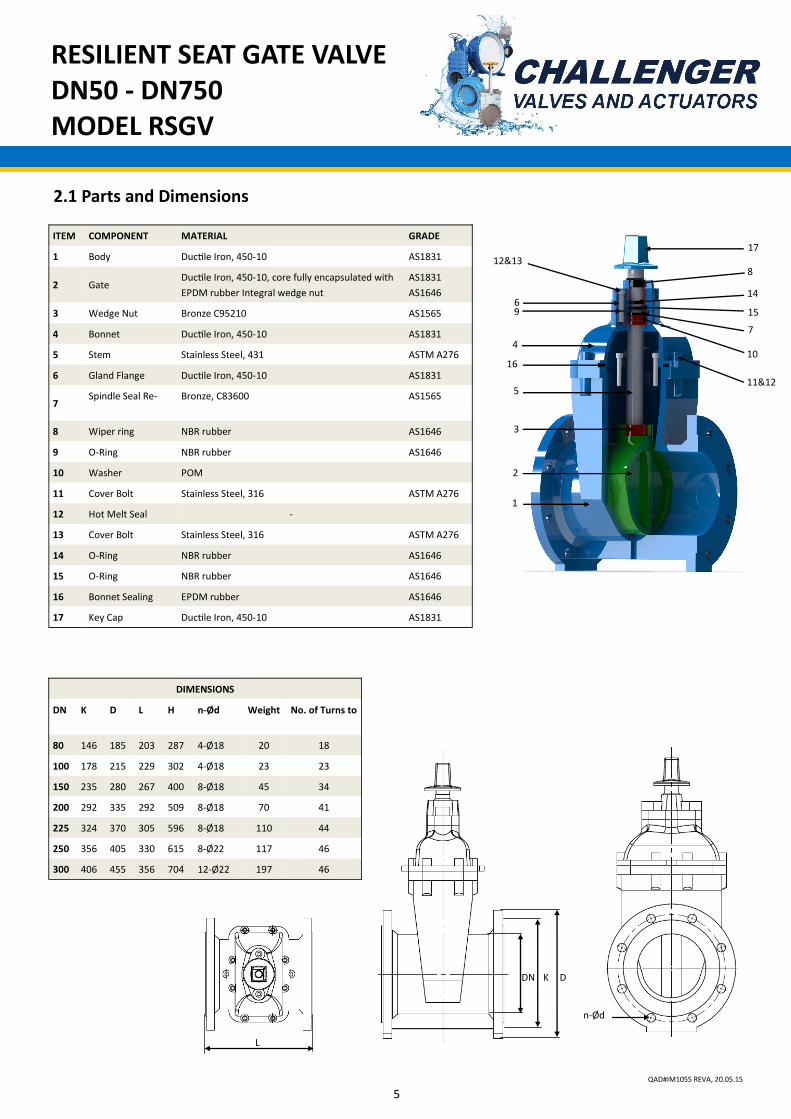
2.1 Parts and Dimensions
1
2
3
4
5
6
8
14
9
K D
L
DN
15
10
17
DIMENSIONS
DN K D L H n-Ød Weight No. of Turns to
80 146 185 203 287 4-Ø18 20 18
100 178 215 229 302 4-Ø18 23 23
150 235 280 267 400 8-Ø18 45 34
200 292 335 292 509 8-Ø18 70 41
225 324 370 305 596 8-Ø18 110 44
250 356 405 330 615 8-Ø22 117 46
300 406 455 356 704 12-Ø22 197 46
n-Ød
ITEM COMPONENT MATERIAL GRADE
1 Body Ductile Iron, 450-10 AS1831
2 Gate Ductile Iron, 450-10, core fully encapsulated with
EPDM rubber Integral wedge nut
AS1831
AS1646
3 Wedge Nut Bronze C95210 AS1565
4 Bonnet Ductile Iron, 450-10 AS1831
5 Stem Stainless Steel, 431 ASTM A276
6 Gland Flange Ductile Iron, 450-10 AS1831
7 Spindle Seal Re- Bronze, C83600 AS1565
8 Wiper ring NBR rubber AS1646
9 O-Ring NBR rubber AS1646
10 Washer POM
11 Cover Bolt Stainless Steel, 316 ASTM A276
12 Hot Melt Seal -
13 Cover Bolt Stainless Steel, 316 ASTM A276
14 O-Ring NBR rubber AS1646
15 O-Ring NBR rubber AS1646
16 Bonnet Sealing EPDM rubber AS1646
17 Key Cap Ductile Iron, 450-10 AS1831
12&13
7
11&12
16
RESILIENT SEAT GATE VALVE DN50 - DN750 MODEL RSGV
6 QAD#IM1055 REVA, 20.05.15
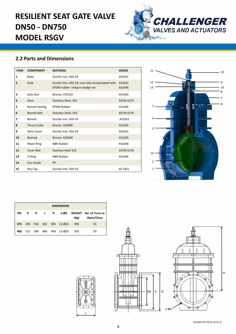
2.2 Parts and Dimensions
ITEM COMPONENT MATERIAL GRADE
1 Body Ductile Iron, 450-10 AS1831
2 Gate Ductile Iron, 450-10, core fully encapsulated with
EPDM rubber Integral wedge nut
AS1831
AS1646
3 Gate Nut Bronze, C95210 AS1565
4 Stem Stainless Steel, 431 ASTM A276
5 Bonnet Sealing EPDM Rubber AS1646
6 Bonnet Bolt Stainless Steel, 316 ASTM A276
7 Bonnet Ductile Iron, 450-10 AS1831
8 Thrust Collar Bronze, C83600 AS1565
9 Stem Cover Ductile Iron, 450-10 AS1831
10 Bearing Bronze, C83600 AS1565
11 Wiper Ring NBR Rubber AS1646
12 Cover Bolt Stainless Steel 316 ASTM A276
13 O-Ring NBR Rubber AS1646
14 Disc Guide PP
15 Key Cap Ductile Iron, 450-10 AS 1831
DIMENSIONS
DN K D L H n-Ød WEIGHT
(Kg)
No. of Turns to
Open/Close
375 495 550 381 905 12-Ø26 290 55
400 521 580 406 940 12-Ø26 303 59
1
2
4
5 6
7
15
DN K D
H
n-Ød
L
14
3
13
12
11
9
10
8
RESILIENT SEAT GATE VALVE DN50 - DN750 MODEL RSGV
7 QAD#IM1055 REVA, 20.05.15
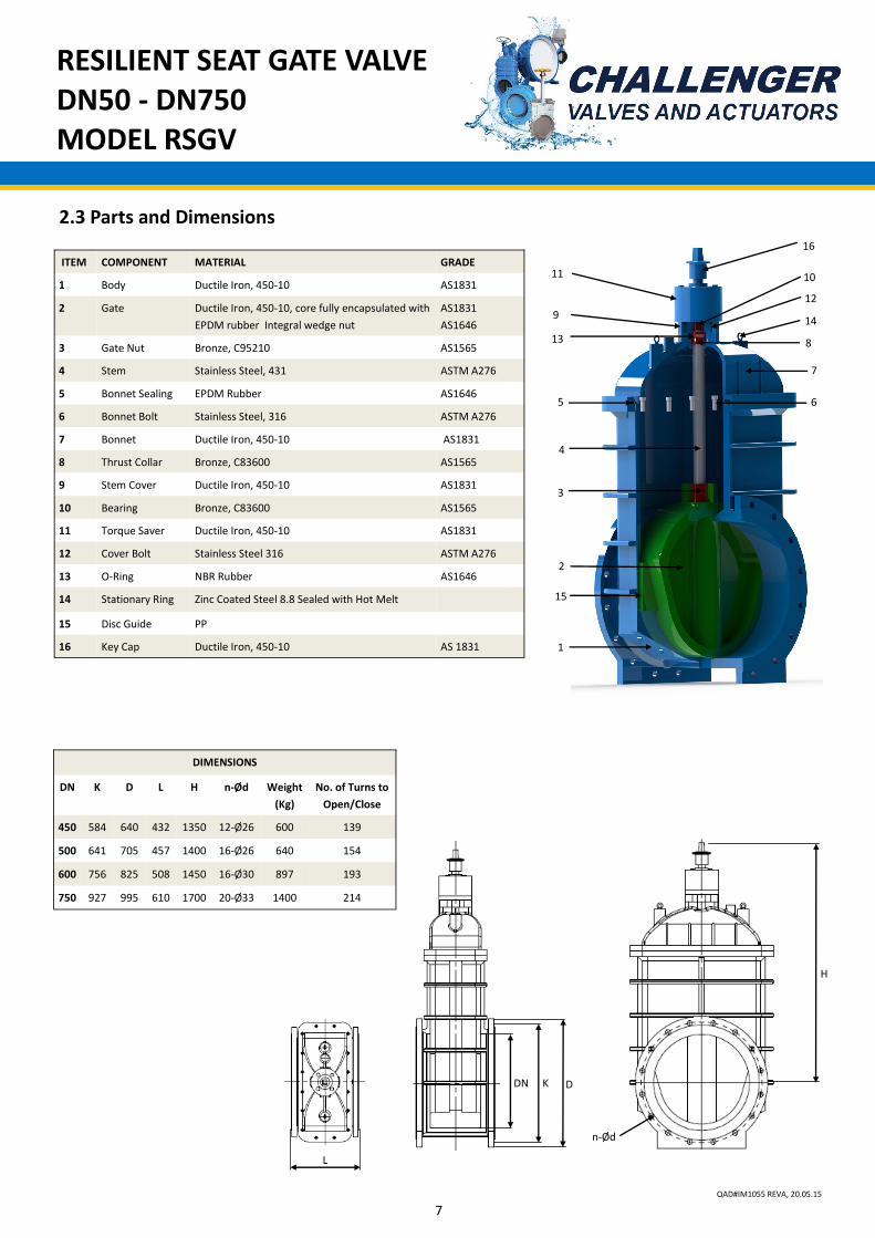
2.3 Parts and Dimensions
ITEM COMPONENT MATERIAL GRADE
1 Body Ductile Iron, 450-10 AS1831
2 Gate Ductile Iron, 450-10, core fully encapsulated with
EPDM rubber Integral wedge nut
AS1831
AS1646
3 Gate Nut Bronze, C95210 AS1565
4 Stem Stainless Steel, 431 ASTM A276
5 Bonnet Sealing EPDM Rubber AS1646
6 Bonnet Bolt Stainless Steel, 316 ASTM A276
7 Bonnet Ductile Iron, 450-10 AS1831
8 Thrust Collar Bronze, C83600 AS1565
9 Stem Cover Ductile Iron, 450-10 AS1831
10 Bearing Bronze, C83600 AS1565
11 Torque Saver Ductile Iron, 450-10 AS1831
12 Cover Bolt Stainless Steel 316 ASTM A276
13 O-Ring NBR Rubber AS1646
14 Stationary Ring Zinc Coated Steel 8.8 Sealed with Hot Melt
15 Disc Guide PP
16 Key Cap Ductile Iron, 450-10 AS 1831
DIMENSIONS
DN K D L H n-Ød Weight
(Kg)
No. of Turns to
Open/Close
450 584 640 432 1350 12-Ø26 600 139
500 641 705 457 1400 16-Ø26 640 154
600 756 825 508 1450 16-Ø30 897 193
750 927 995 610 1700 20-Ø33 1400 214
1
2
4
5 6
7
16
DN K D
H
n-Ød
L
3
13
12
11 10
14
8
9
15
RESILIENT SEAT GATE VALVE DN50 - DN750 MODEL RSGV
8 QAD#IM1055 REVA, 20.05.15
INSTALLATION, OPERATION AND MAINTENANCE
3.1 Preparation before installation of gate valve
Valves should be protected during transportation. Collision and falling should be avoided during transportation and installation.
It is strictly prohibited to lift from the lever arm directly.
Due to RSGV comprising rubber components, they are not to be stored exposed outdoors or exposed in sunshine for long
periods of time.
If the valve is installed in a pit, enough space shall be kept to accommodate the working personnel.
The pipelines shall be designed with supporting fixtures such as support frames. It is strictly prohibited for the valve to support
the pipeline weight or external weight.
Prior to connecting the valve with the pipeline, the flange shall be welded to the pipe. It is strictly prohibited to clamp the valve
during the flange welding.
Foreign materials shall be cleared from the pipelines. It is strictly prohibited to leave weld slag, stones or other foreign
materials in the pipeline which could damage the valve.
Prior to installation of the valve, prepare handling tools, spanners and other necessary tools, gaskets, bolts (or studs), nuts and
washers. Bolts and nuts shall meet the pipeline design requirements. It is strictly prohibited to use fasteners without
sufficient strength.
3.2 Installation of gate valve
When installing the gate valves, ensure that the seat and the flange faces are clean.
When valves are provided with lifting lugs, plates or eye nuts, these must be used to lift the valve.
To ensure adequate sealing it is important to select the correct type of gasket for the medium
concerned, gaskets with the correct flange size must be used.
Place valve between pipe flanges and insert the bolts.
Tighten bolts loosely.
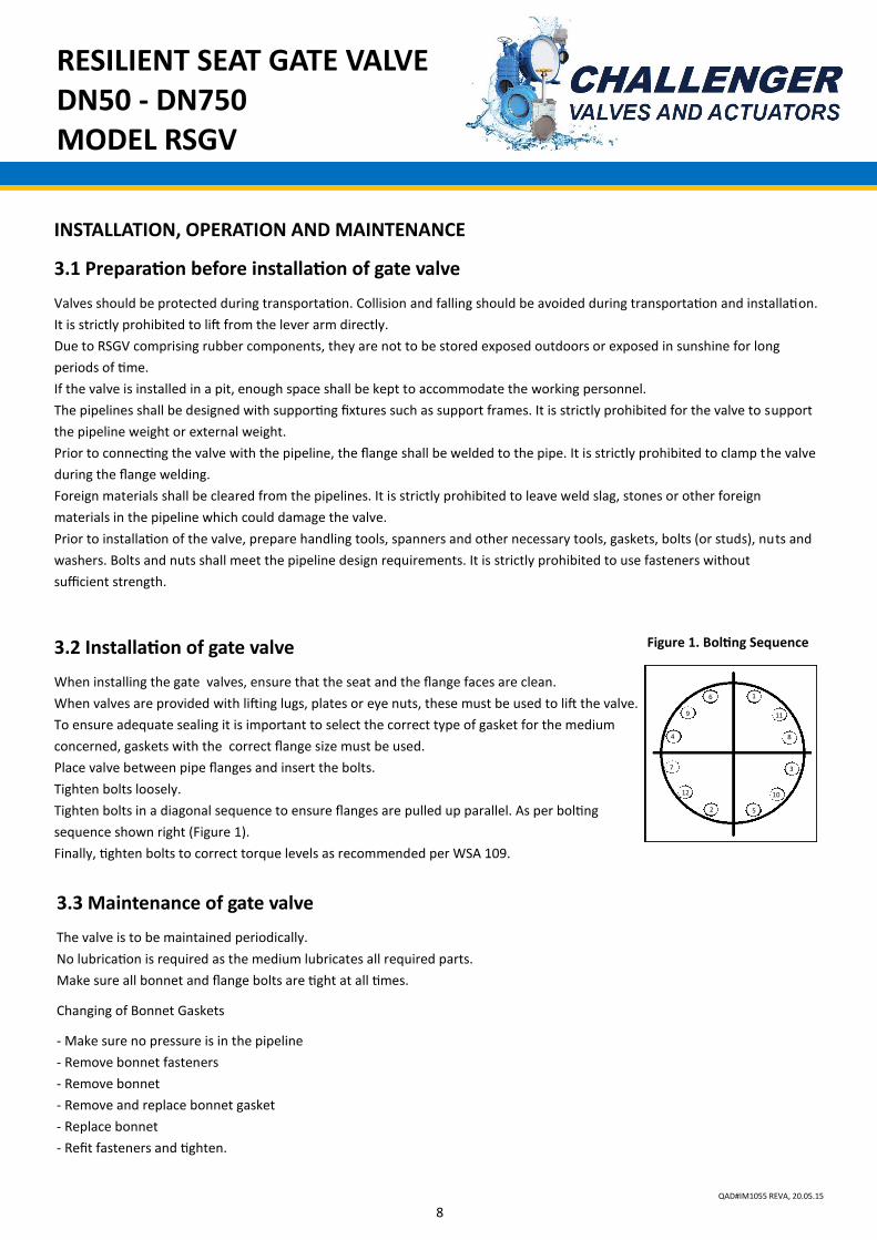
Tighten bolts in a diagonal sequence to ensure flanges are pulled up parallel. As per bolting
sequence shown right (Figure 1).
Finally, tighten bolts to correct torque levels as recommended per WSA 109.
3.3 Maintenance of gate valve
The valve is to be maintained periodically.
No lubrication is required as the medium lubricates all required parts.
Make sure all bonnet and flange bolts are tight at all times.
Changing of Bonnet Gaskets
- Make sure no pressure is in the pipeline
- Remove bonnet fasteners
- Remove bonnet
- Remove and replace bonnet gasket
- Replace bonnet
- Refit fasteners and tighten.
1
2
11
8
3
10
5
12
7
4
9
6
Figure 1. Bolting Sequence
RESILIENT SEAT GATE VALVE DN50 - DN750 MODEL RSGV
9 QAD#IM1055 REVA, 20.05.15
RESILIENT SEAT GATE VALVE DN50 - DN750 MODEL RSGV
10 QAD#IM1055 REVA, 20.05.15
RESILIENT SEAT GATE VALVE DN50 - DN750 MODEL RSGV
11 QAD#IM1055 REVA, 20.05.15

![[MS-WSPOL]: Web Services: Policy Assertions and WSDL ...... · [WSDL]. processing operation: A WSDL operation that is not a terminating operation. terminating operation: A WSDL operation](https://img.pdfslide.us/doc/110x75/5fee0a69f9c7494e656bdefe/ms-wspol-web-services-policy-assertions-and-wsdl-wsdl-processing.jpg)