Embed Size (px)
Citation preview
Version 7/01/17
INSTALLATION, OPERATION & MAINTENANCE MANUAL
XP-KZN SERIES
EXPLOSION PROOF SUBMERSIBLE SLURRY PUMPS
(CLASS 1, DIVISION 1, GROUPS C&D):
Three Phase 230V, 460V & 575V
CAST IRON
THREE PHASE
XP-KZN37 XP-KZN55 XP-KZN55CH XP-KZN75
Read this manual carefully before installing, operating or servicing these pump models. Observe all safety information. Failure to comply with instructions may result in personal injury and/or property damage. Please retain these instructions.

Version 7/01/17
3
TABLE OF CONTENTS
INTRODUCTION ............................................................................................................................................................ 4 HSAFETY ......................................................................................................................................................................... 5 INSPECTION ................................................................................................................................................................. 6
PRE-INSTALLATION INSPECTION ......................................................................................................................... 6 OIL FILL QUANTITY/TYPE ....................................................................................................................................... 6 PUMP INSTALLATION ............................................................................................................................................. 6 POSITIONING THE PUMP ....................................................................................................................................... 7 WIRING INSTRUCTIONS ......................................................................................................................................... 7 PUMP ROTATION .................................................................................................................................................... 8
PUMP OPERATION ....................................................................................................................................................... 9 TYPICAL MANUAL DEWATERING INSTALLATION ..................................................................................................... 9
MANUAL OPERATION ............................................................................................................................................. 9 STOPPING ................................................................................................................................................................ 9
TYPICAL AUTOMATIC DEWATERING INSTALLATION .............................................................................................. 9 STOPPING .............................................................................................................................................................. 10
INTENDED METHODS OF CONNECTION ................................................................................................................. 11 THREE PHASE WIRING INSTRUCTION ............................................................................................................... 12
TROUBLE SHOOTING ................................................................................................................................................ 13 PUMP WILL NOT RUN ........................................................................................................................................... 13 PUMP RUNS BUT DOES NOT DELIVER RATED CAPACITY ............................................................................... 13 SERVICING YOUR SUBMERSIBLE PUMP............................................................................................................ 14 MAINTAINING YOUR PUMP .................................................................................................................................. 15 CHANGING SEAL OIL ............................................................................................................................................ 15 CHANGING SEALS* ............................................................................................................................................... 16
EXPLODED VIEW OF XP-KZN37, 55, 55CH, 75 ........................................................................................................ 17 XP-KZN SERIES PARTS LIST .................................................................................................................................... 19 THREE PHASE WIRING DIAGRAMS ......................................................................................................................... 20
230V (5 LEAD) ........................................................................................................................................................ 20 MODELS XP-KZN37, 55, 55CH ......................................................................................................................... 20
460V (5 LEAD) ........................................................................................................................................................ 21 MODELS XP-KZN37, 55, 55CH, 75 ................................................................................................................... 21
575V (5 LEAD) ........................................................................................................................................................ 22 MODELS XP-KZN37, 55, 55CH, 75 ................................................................................................................... 23
SEAL MINDER® - THERMAL MOTOR SENSOR SWITCH ........................................................................................ 23 WARRANTY AND LIMITATION OF LIABILITY ............................................................................................................ 26 START-UP REPORT FORM ........................................................................................................................................ 27 NOTES: ........................................................................................................................................................................ 30
4
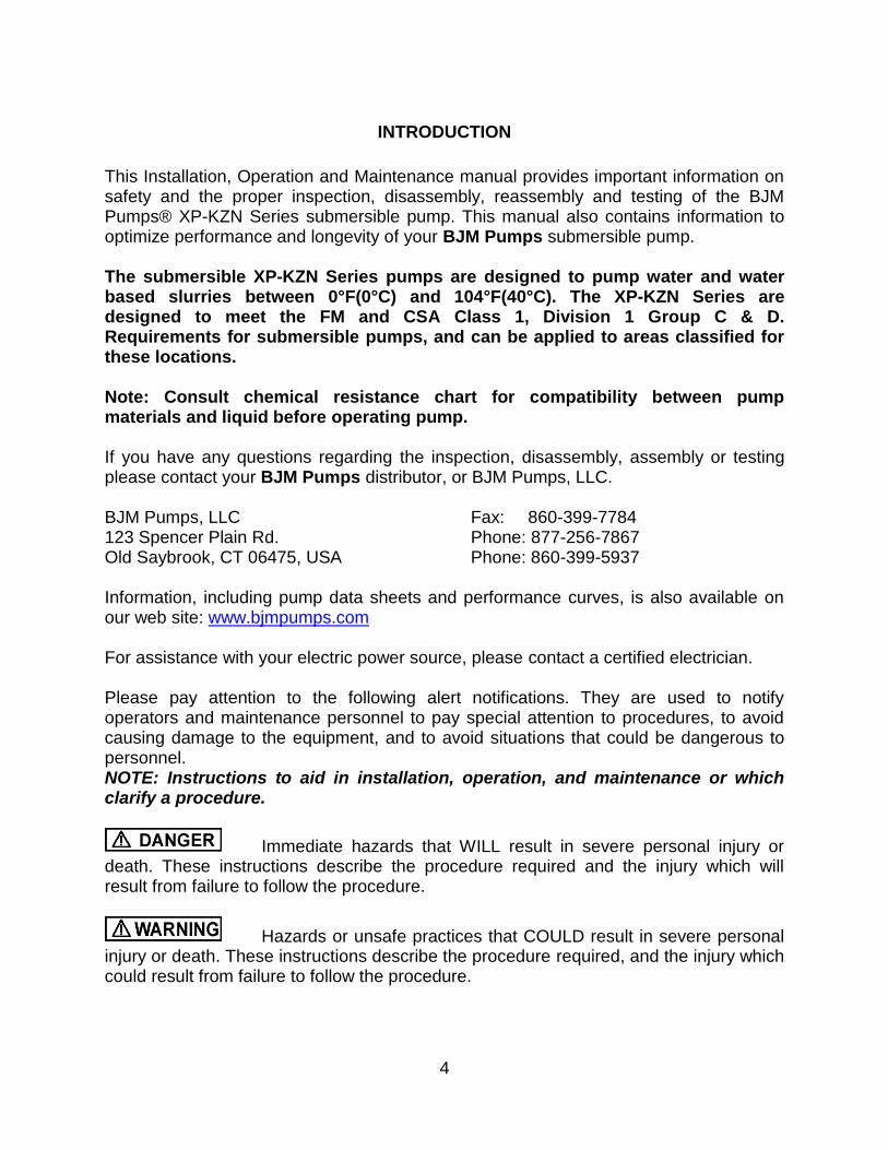
INTRODUCTION
This Installation, Operation and Maintenance manual provides important information on safety and the proper inspection, disassembly, reassembly and testing of the BJM Pumps® XP-KZN Series submersible pump. This manual also contains information to optimize performance and longevity of your BJM Pumps submersible pump. The submersible XP-KZN Series pumps are designed to pump water and water based slurries between 0°F(0°C) and 104°F(40°C). The XP-KZN Series are designed to meet the FM and CSA Class 1, Division 1 Group C & D. Requirements for submersible pumps, and can be applied to areas classified for these locations. Note: Consult chemical resistance chart for compatibility between pump materials and liquid before operating pump. If you have any questions regarding the inspection, disassembly, assembly or testing please contact your BJM Pumps distributor, or BJM Pumps, LLC. BJM Pumps, LLC 123 Spencer Plain Rd. Old Saybrook, CT 06475, USA
Fax: 860-399-7784 Phone: 877-256-7867 Phone: 860-399-5937
Information, including pump data sheets and performance curves, is also available on our web site: HUwww.bjmpumps.com U For assistance with your electric power source, please contact a certified electrician. Please pay attention to the following alert notifications. They are used to notify operators and maintenance personnel to pay special attention to procedures, to avoid causing damage to the equipment, and to avoid situations that could be dangerous to personnel. NOTE: Instructions to aid in installation, operation, and maintenance or which clarify a procedure.
Immediate hazards that WILL result in severe personal injury or death. These instructions describe the procedure required and the injury which will result from failure to follow the procedure.
Hazards or unsafe practices that COULD result in severe personal injury or death. These instructions describe the procedure required, and the injury which could result from failure to follow the procedure.
5
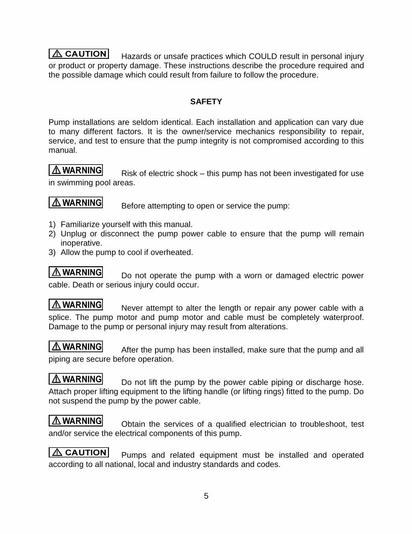
Hazards or unsafe practices which COULD result in personal injury or product or property damage. These instructions describe the procedure required and the possible damage which could result from failure to follow the procedure.
HSAFETY
Pump installations are seldom identical. Each installation and application can vary due to many different factors. It is the owner/service mechanics responsibility to repair, service, and test to ensure that the pump integrity is not compromised according to this manual.
Risk of electric shock – this pump has not been investigated for use in swimming pool areas.
Before attempting to open or service the pump: 1) Familiarize yourself with this manual. 2) Unplug or disconnect the pump power cable to ensure that the pump will remain
inoperative. 3) Allow the pump to cool if overheated.
Do not operate the pump with a worn or damaged electric power cable. Death or serious injury could occur.
Never attempt to alter the length or repair any power cable with a splice. The pump motor and pump motor and cable must be completely waterproof. Damage to the pump or personal injury may result from alterations.
After the pump has been installed, make sure that the pump and all piping are secure before operation.
Do not lift the pump by the power cable piping or discharge hose. Attach proper lifting equipment to the lifting handle (or lifting rings) fitted to the pump. Do not suspend the pump by the power cable.
Obtain the services of a qualified electrician to troubleshoot, test and/or service the electrical components of this pump.
Pumps and related equipment must be installed and operated according to all national, local and industry standards and codes.
6
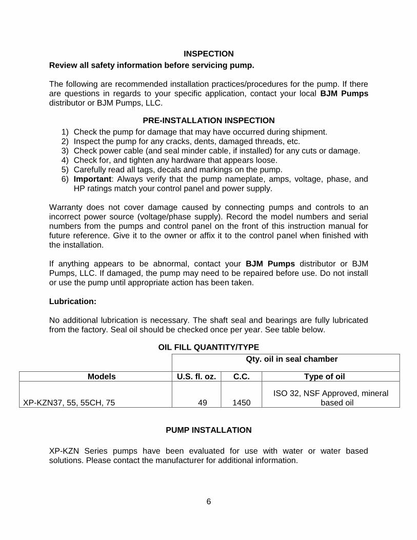
INSPECTION
Review all safety information before servicing pump. The following are recommended installation practices/procedures for the pump. If there are questions in regards to your specific application, contact your local BJM Pumps distributor or BJM Pumps, LLC.
PRE-INSTALLATION INSPECTION
1) Check the pump for damage that may have occurred during shipment. 2) Inspect the pump for any cracks, dents, damaged threads, etc. 3) Check power cable (and seal minder cable, if installed) for any cuts or damage. 4) Check for, and tighten any hardware that appears loose. 5) Carefully read all tags, decals and markings on the pump. 6) Important: Always verify that the pump nameplate, amps, voltage, phase, and
HP ratings match your control panel and power supply. Warranty does not cover damage caused by connecting pumps and controls to an incorrect power source (voltage/phase supply). Record the model numbers and serial numbers from the pumps and control panel on the front of this instruction manual for future reference. Give it to the owner or affix it to the control panel when finished with the installation. If anything appears to be abnormal, contact your BJM Pumps distributor or BJM Pumps, LLC. If damaged, the pump may need to be repaired before use. Do not install or use the pump until appropriate action has been taken. Lubrication: No additional lubrication is necessary. The shaft seal and bearings are fully lubricated from the factory. Seal oil should be checked once per year. See table below.
OIL FILL QUANTITY/TYPE
Qty. oil in seal chamber
Models U.S. fl. oz. C.C. Type of oil
XP-KZN37, 55, 55CH, 75 49 1450 ISO 32, NSF Approved, mineral
based oil
PUMP INSTALLATION
XP-KZN Series pumps have been evaluated for use with water or water based solutions. Please contact the manufacturer for additional information.
7
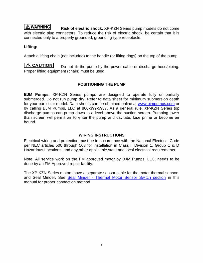
Risk of electric shock. XP-KZN Series pump models do not come with electric plug connectors. To reduce the risk of electric shock, be certain that it is connected only to a properly grounded, grounding-type receptacle. Lifting: Attach a lifting chain (not included) to the handle (or lifting rings) on the top of the pump.
Do not lift the pump by the power cable or discharge hose/piping. Proper lifting equipment (chain) must be used.
POSITIONING THE PUMP
BJM Pumps, XP-KZN Series pumps are designed to operate fully or partially submerged. Do not run pump dry. Refer to data sheet for minimum submersion depth for your particular model. Data sheets can be obtained online at HUwww.bjmpumps.com UH or by calling BJM Pumps, LLC at 860-399-5937. As a general rule, XP-KZN Series top discharge pumps can pump down to a level above the suction screen. Pumping lower than screen will permit air to enter the pump and cavitate, lose prime or become air bound.
WIRING INSTRUCTIONS
Electrical wiring and protection must be in accordance with the National Electrical Code per NEC articles 500 through 503 for installation in Class I, Division 1, Group C & D Hazardous Locations, and any other applicable state and local electrical requirements. Note: All service work on the FM approved motor by BJM Pumps, LLC, needs to be done by an FM Approved repair facility. The XP-KZN Series motors have a separate sensor cable for the motor thermal sensors and Seal Minder. See Seal Minder - Thermal Motor Sensor Switch section in this manual for proper connection method
8
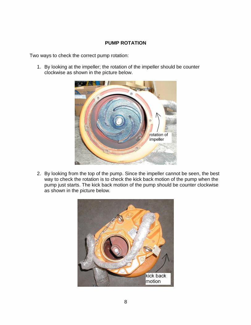
PUMP ROTATION
Two ways to check the correct pump rotation:
1. By looking at the impeller; the rotation of the impeller should be counter clockwise as shown in the picture below.
2. By looking from the top of the pump. Since the impeller cannot be seen, the best way to check the rotation is to check the kick back motion of the pump when the pump just starts. The kick back motion of the pump should be counter clockwise as shown in the picture below.
9
PUMP OPERATION
This pump is designed to handle dirty water and slurries that contains some solids. Do not attempt to pump any liquids which may damage the pump or endanger personnel as a result of pump failure.
This pump is designed to operate in approved class 1, division 1, group C & D locations. Do not operate this pump in non approved locations. Death or Serious injury will result.
TYPICAL MANUAL DEWATERING INSTALLATION
NOTE: Maximum recommended starts should not exceed 10 times per hour.
MANUAL OPERATION
All XP-KZN models are provided with a 50’ (10m) power cord. UNEVERU splice the power cable due to safety and warranty considerations. Always keep the control connection end of cable dry. Note: Three phase units do not have a plug and are to be wired into an approved control box/panel as specified by hazard zone.
Do not alter the length or repair any power cable with a splice. The pump motor and cable must be completely waterproof. Damage to the pump or personal injury may result from alterations. For manual operation: Connect directly to an NEC approved control box. Check the direction of the rotation. Tilt the pump and start it. It should twist in the opposite direction of the arrow (on pump). It is recommended that a Ground Fault Interrupter (GFI) type circuit (or equivalent) be used.
STOPPING
To stop the pump (manual and automatic model), turn off the breaker or the power disconnect.
TYPICAL AUTOMATIC DEWATERING INSTALLATION
NOTE: Maximum recommended starts should not exceed 10 times per hour.
10
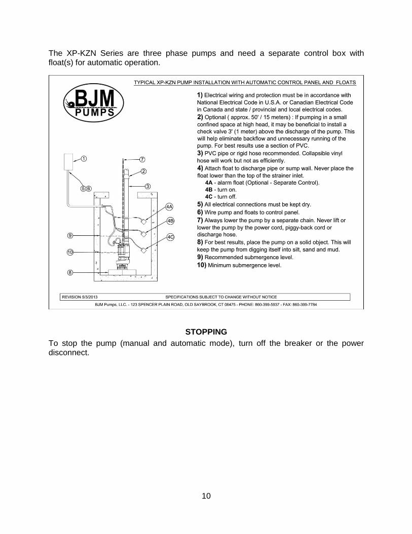
The XP-KZN Series are three phase pumps and need a separate control box with float(s) for automatic operation.
STOPPING
To stop the pump (manual and automatic mode), turn off the breaker or the power disconnect.
11
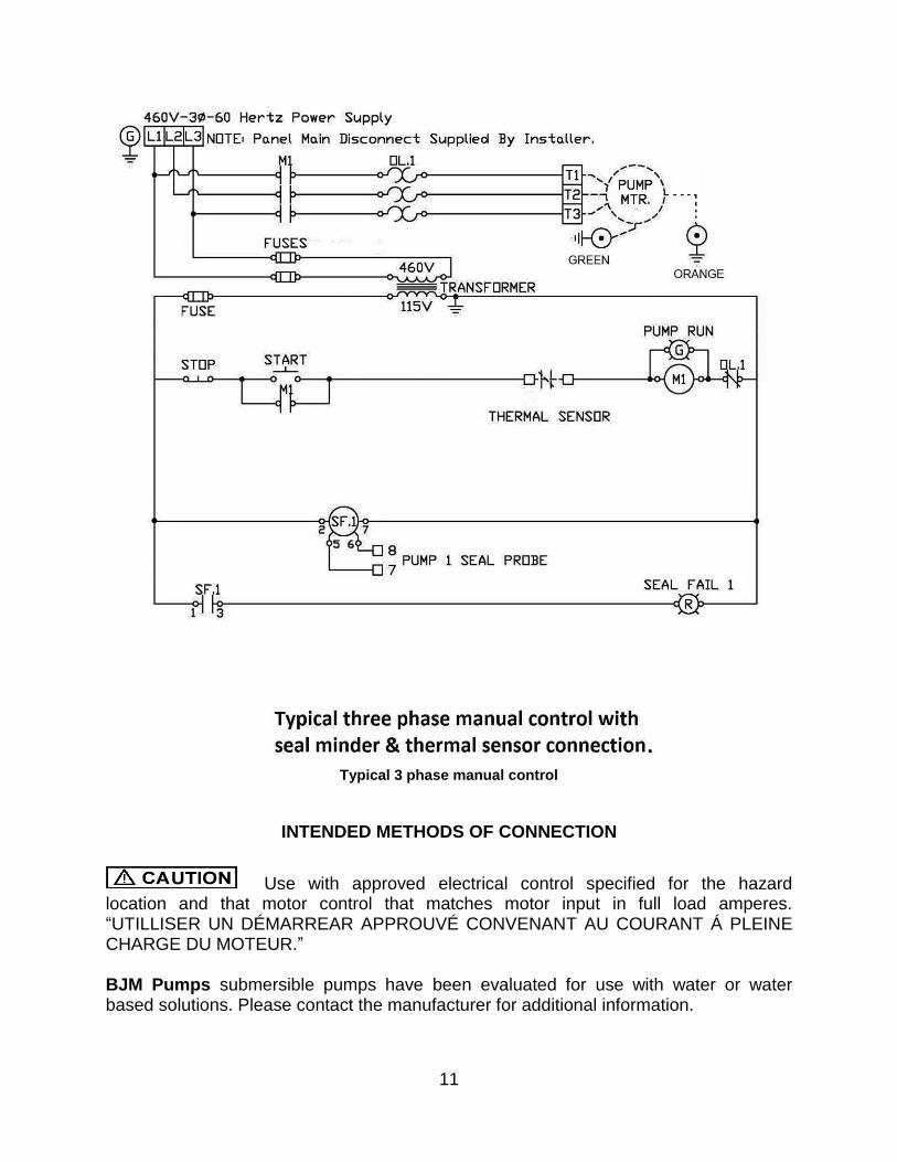
Typical 3 phase manual control
INTENDED METHODS OF CONNECTION
Use with approved electrical control specified for the hazard location and that motor control that matches motor input in full load amperes. “UTILLISER UN DÉMARREAR APPROUVÉ CONVENANT AU COURANT Á PLEINE CHARGE DU MOTEUR.” BJM Pumps submersible pumps have been evaluated for use with water or water based solutions. Please contact the manufacturer for additional information.
12
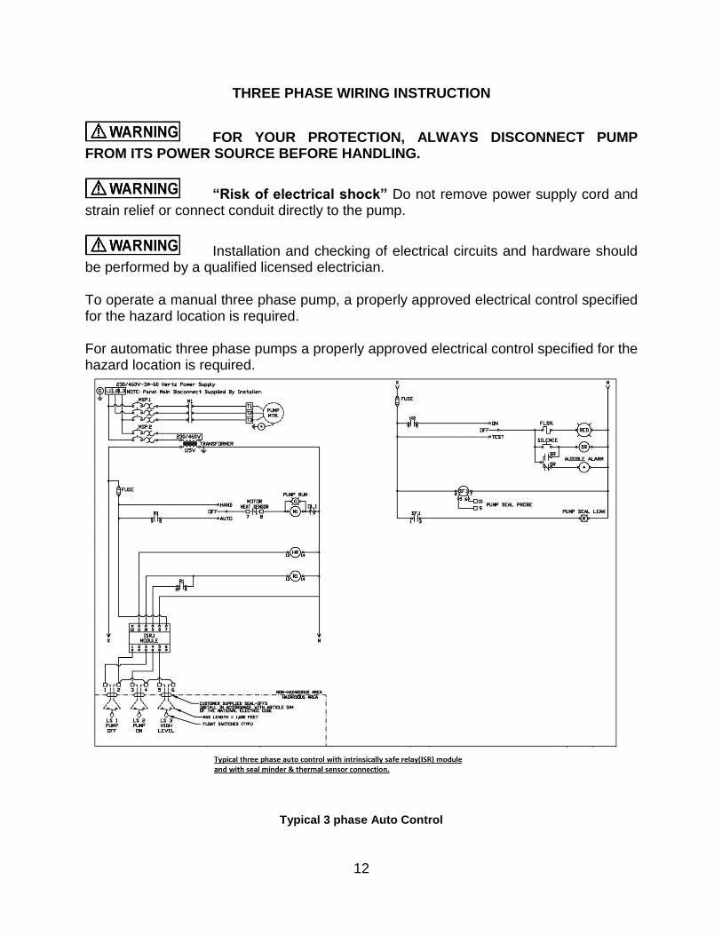
THREE PHASE WIRING INSTRUCTION
FOR YOUR PROTECTION, ALWAYS DISCONNECT PUMP FROM ITS POWER SOURCE BEFORE HANDLING.
“Risk of electrical shock” Do not remove power supply cord and strain relief or connect conduit directly to the pump.
Installation and checking of electrical circuits and hardware should be performed by a qualified licensed electrician. To operate a manual three phase pump, a properly approved electrical control specified for the hazard location is required. For automatic three phase pumps a properly approved electrical control specified for the hazard location is required.
Typical 3 phase Auto Control
13
Before installing a pump, make sure both of the ground leads and the power leads have been connected properly per NEC hazard zone code requirements. Once the power connections have been confirmed, then check the pump rotation. Momentarily energize the pump, observing the directions of kick back due to starting torque. Rotation is correct if kick back is in the opposite direction of the arrow on the pump casing. If rotation is not correct, switching of any two power leads (other than ground) will provide the proper rotation. Three phase pumps have integral motor motor winding thermal sensors that are wired with start control circuit. It is recommended that all three phase pumps using a motor starting device also incorporate motor overload protection. Pumps must be installed in accordance with the NEC hazard location code requirements and the National Electrical Code requirements as well as all applicable local codes and ordinances. The XP-KZN Series pumps are designed for hazardous applications in accordance with National Electrical Code, ANSI/NFPA 70. Connect pump to control box/panel that is approved for the application. The provision for supply connection shall reduce the risk of water entry during temporary, limited submersion.
TROUBLE SHOOTING
Disconnect the power source to the pump BEFORE attempting any type of trouble shooting, service or repair.
PUMP WILL NOT RUN
1. Check power supply (fuses, breaker). Reset power. 2. Blocked impeller. Remove strainer, check and clean. 3. Defective cable or incorrect wiring. 4. Strainer clogged. Check and clean as necessary. 5. Float switch tangled/obstructed. Clean and free float switch from obstruction. 6. Float switch defective. Replace float switch. 7. Pump overheated or temperature of liquid exceeds pump operating
temperature. U
PUMP RUNS BUT DOES NOT DELIVER RATED CAPACITY
1. Discharge line clogged, restricted or hose kinked. Check discharge hose/pipe. 2. Worn impeller and/or suction cover. Inspect and replace as necessary. 3. Pump overloaded due to liquid pumped being too thick. 4. Pumping air. Check liquid level and position of pump. 5. Excessive voltage drops due to long cables.
14
6. Three phase only; pump running backwards, check rotation.
SERVICING YOUR SUBMERSIBLE PUMP
Pump should be disconnected from the electric power supply before proceeding to do any service or maintenance. To service or repair your pump, please contact your local BJM Pumps distributor. Service should only be performed by a qualified electrician. Repair requiring disassembly of the pump motor must be done at BJM Pump or at an FM approved motor shop only.
15
MAINTAINING YOUR PUMP
Pump should be disconnected from the electric power supply before proceeding to do any service or maintenance.
Pump should be inspected at regular intervals.
More frequent inspections are required if the pump is used in a harsh environment.
Preventative maintenance should be performed to reduce the chance of premature failure.
Worn impellers and lip seals should be replaced.
Cut or cracked power cords must be replaced. (Never operate a pump with a cut, cracked or damaged power cord.)
Seal oil should be checked once per year.
Maintenance should always be done when taking a pump out of service before storage.
1) Clean pump of dirt and other build up. 2) Check condition of oil around the shaft seals. 3) Check hydraulic parts: check for wear. 4) Inspect power cable. Make sure that it is free of nicks or cuts. 5)
CHANGING SEAL OIL
Changing the seal oil in the XP-KZN Series pumps is very easy.
1) Make sure that the pump cable is disconnected from the power source. 2) Lay the pump down on its side. 3) Remove the screws that hold the bottom plate in place. 4) Remove bottom plate. 5) Remove screws holding the suction cover. 6) Remove the suction cover. 7) Remove the impeller. 8) Remove the inspection screw for the oil chamber (pos#50-08). Pour out a
small sample of the oil. If it is milky white, or contains water, then the oil and possible, the mechanical seal, should be changed. If an oil change is needed:
9) Remove the screws that hold the oil chamber cover in place & remove the oil. 10) Replace the mechanical seal if necessary. 11) Replace the oil. 12) Assemble the pump.
16
CHANGING SEALS*
1) Make sure that the pump cable is disconnected from the power source. 2) Lay the pump down on its side. 3) Remove the oil inspection bolt (pos#50-11) from the oil seal chamber. 4) Drain out all the inside the oil seal chamber. 5) Remove the bolts holding the stand. 6) Remove the stand. 7) Remove the bolts holding the suction cover. 8) Remove the suction cover. 9) Remove the agitator. 10) Remove the impeller, impeller key and shims. 11) Remove the bolts holding the pump housing. 12) Remove the pump housing. 13) Remove the shaft sleeve. Note the shaft sleeve direction. 14) Remove the bots holding the oil cover. 15) Remove the oil cover. 16) Remove the screws holding the seal retainer. 17) Remove the seal retainer. 18) Remove the mechanical seal. 19) Replace the mechanical seal, lip seal and o-rings. 20) Assemble the pump. 21) Fill with recommended new oil. 22) Replace the oil inspection bolt o-ring. 23) Secure the oil inspection bolt.
*Note: If there is excessive liquid found in the oil or mechanical seal damaged, please contact BJM Pumps authorized service centers.
17
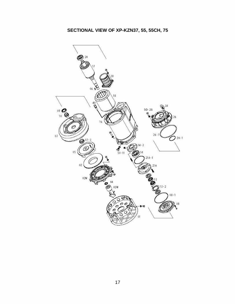
SECTIONAL VIEW OF XP-KZN37, 55, 55CH, 75
18
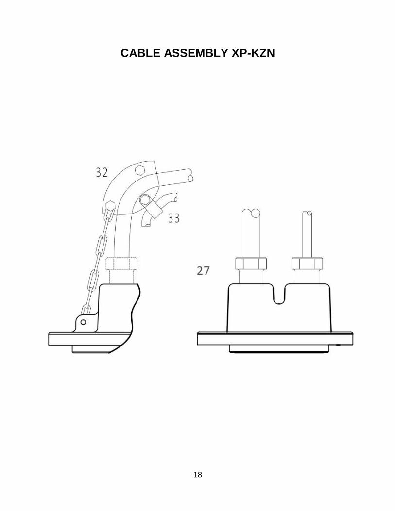
CABLE ASSEMBLY XP-KZN
19
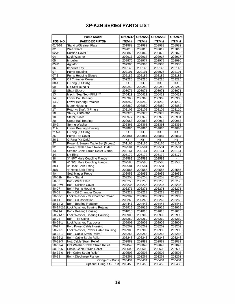
XP-KZN SERIES PARTS LIST
Pump Model XPKZN37 XPKZN55 XPKZN55CH XPKZN75
POS. NO. PART DESCRIPTON ITEM # ITEM # ITEM # ITEM #01N-01 Stand w/Strainer Plate 201982 201982 201983 201982
02 Wear Plate 202018 202018 202019 202018
02W Suction Cover 202869 202869 202870 202873
04 Lock Washer 202917 202917 202917 202917
05 Impeller 202976 202977 202979 202980
05W Agitator 202983 202983 202983 202983
06 Impeller Key 202146 202146 202146 202146
07 Pump Housing 202191 202191 203026 202191
07-3 Pump Housing Sleeve 202182 202182 202182 202182
08 Oil Chamber Cover 202225 202225 202225 202225
08-1 O-Ring (Kit Only) Kit Kit Kit Kit
09 Lip Seal Buna N 202248 202248 202248 202248
10 Shaft Sleeve 203071 203071 203071 203071
13 Mech. Seal Set - FKM *** 200419 200419 200419 200419
14 Lower Ball Bearing 200963 200963 200963 200963
14-2 Lower Bearing Retainer 204252 204252 204252 204252
16 Motor Housing 203880 203880 203880 203882
17 Rotor w/Shaft, 3 Phase 203108 203109 203109 203110
18 Stator, 230/460V 203976 203978 203978 203980
18 Stator, 575V 203977 203979 203979 203981
20 Upper Ball Bearing 200968 200968 200968 200968
20-2 Spring Washer 202361 202361 202361 202361
21A Lower Bearing Housing 203886 203886 203886 203886
21A-1 O-Ring (Kit Only) Kit Kit Kit Kit
26 Pump Top Cover 203884 203884 203884 203884
26-1 O-Ring (Kit Only) Kit Kit Kit Kit
27 Power & Sensor Cable Set (5 Lead) 201166 201166 201166 201166
32 Power Cable Strain Relief Holder 202501 202501 202501 202501
33 Sensor Cable Strain Relief Clamp 203161 203161 203161 203161
34 Lift Ring 203172 203172 203172 203172
38 3" NPT Male Coupling Flange 202583 202583 202583 -
38 4" NPT Male Coupling Flange 202585 202585 202585 202585
38B 3" Hose Barb Fitting 202584 202584 202584 -
38B 4" Hose Barb Fitting 202586 202586 202586 202586
40 Seal Minder Probe 203958 203958 203958 203958
50-01N Bolt - Stand 203258 203258 203258 203258
50-02 Bolt - Wear Plate 203253 203253 203253 203253
50-02W Bolt - Suction Cover 203236 203236 203236 203236
50-07 Bolt - Pump Housing 203271 203271 203271 203271
50-08 Bolt - Oil Chamber Cover 203229 203229 203229 203229
50-08-1 Lock Washer - Oil Chamber Cover 202902 202902 202902 202902
50-11 Bolt - Oil Inspection 203268 203268 203268 203268
50-14-2 Bolt - Bearing Retainer 204446 204446 204446 204446
50-14-2-1 Lock Washer, Bearing Retainer 202915 202915 202915 202915
50-21A Bolt - Bearing Housing 201013 201013 201013 201013
50-21A-1 Lock Washer, Bearing Housing 202909 202909 202909 202909
50-26 Bolt - Top Cover 203260 203260 203260 203260
50-26-1 Lock Washer, Top cover 202905 202905 202905 202905
50-27 Bolt, Power Cable Housing 203262 203262 203262 203262
50-27-1 Lock Washer, Power Cable Housing 202909 202909 202909 202909
50-32-1 Bolt - Cable Strain Relief 203256 203256 203256 203256
50-32-2 Bolt - Cable Strain Relief 203246 203246 203246 203246
50-32-3 Nut, Cable Strain Relief 202889 202889 202889 202889
50-32-4 Flat Washer Cable Strain Relief 202049 202049 202049 202049
50-32-5 Chain, Cable Strain Relief 202502 202502 202502 202502
50-32-6 Pin, Cable Strain Relief 202503 202503 202503 202503
50-38 Bolt - Discharge Flange 203262 203262 203262 203262
Oring-Kit - Buna 200434 200434 200434 200434
Optional Oring-Kit - FKM 200450 200450 200450 200450
20
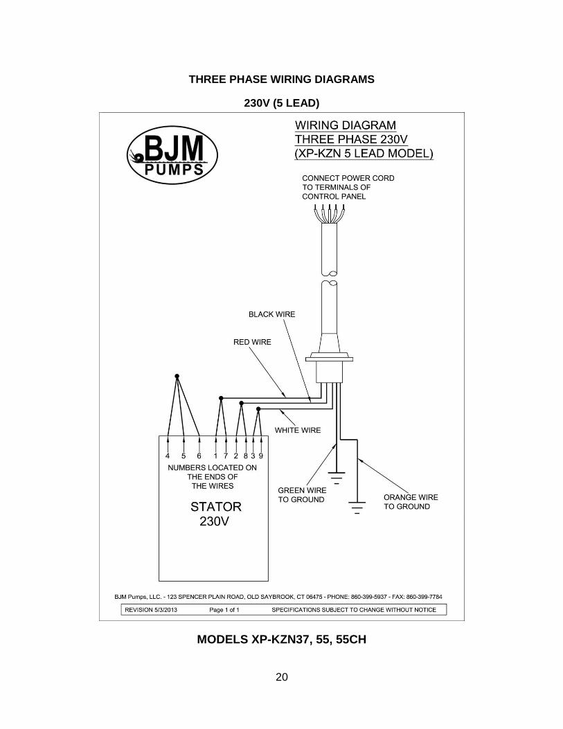
THREE PHASE WIRING DIAGRAMS
230V (5 LEAD)
MODELS XP-KZN37, 55, 55CH
21
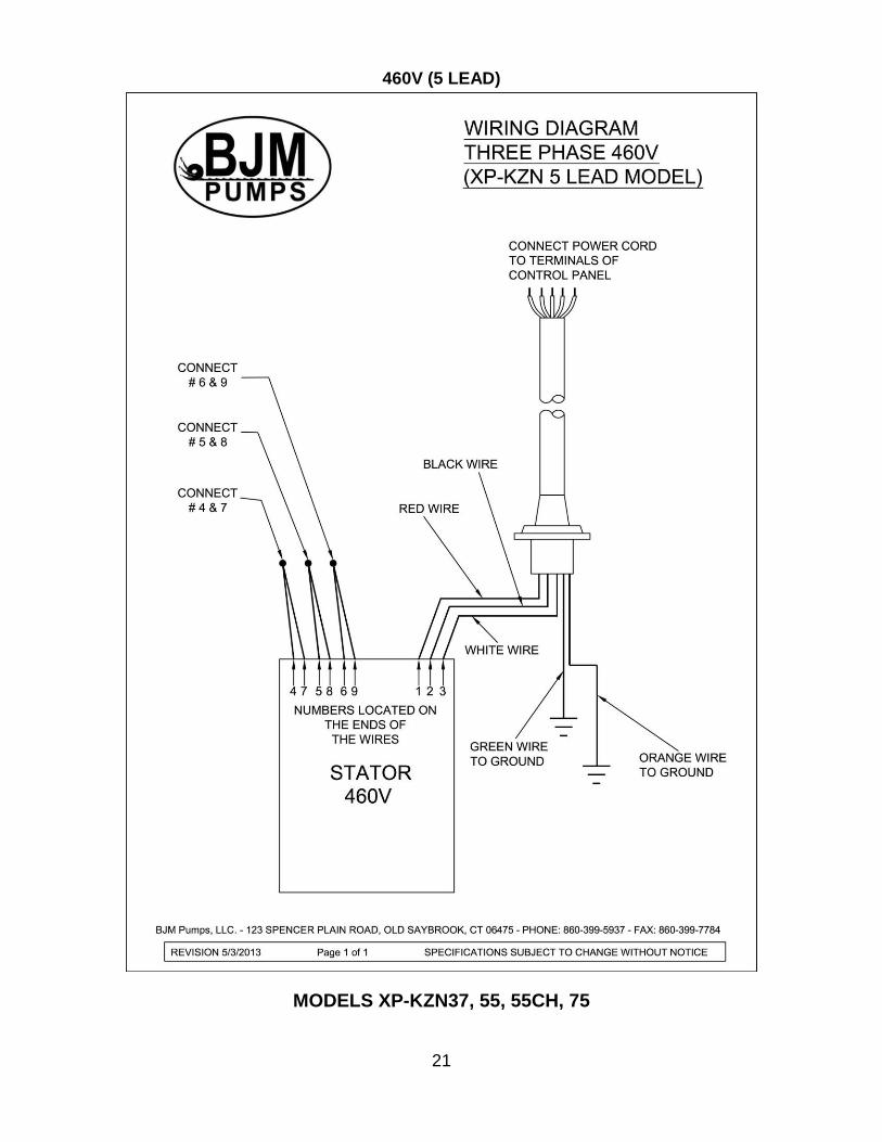
460V (5 LEAD)
MODELS XP-KZN37, 55, 55CH, 75
22
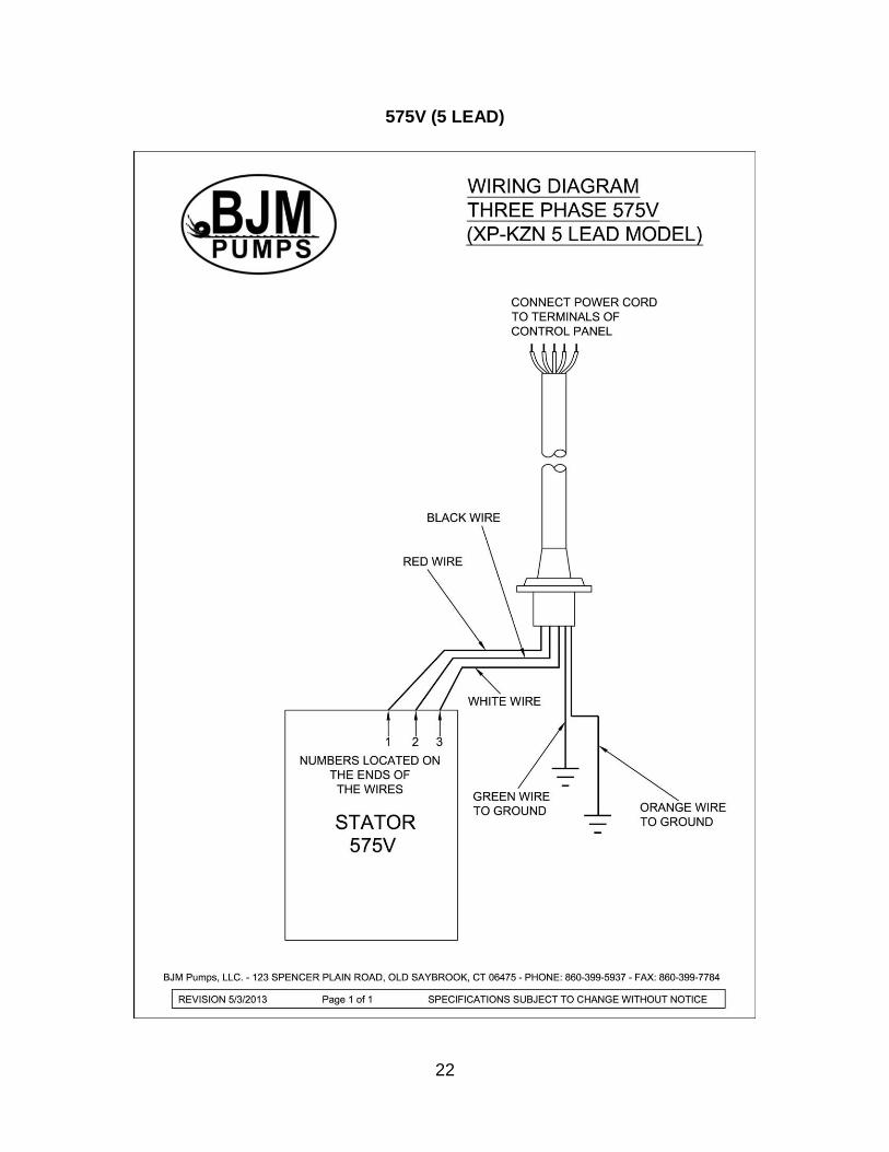
575V (5 LEAD)
23
MODELS XP-KZN37, 55, 55CH, 75
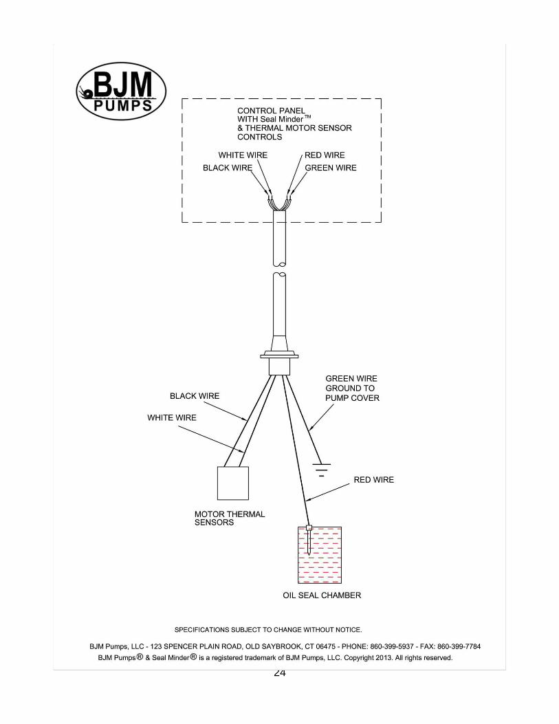
SEAL MINDER® - THERMAL MOTOR SENSOR SWITCH
Seal Minder: Also known as a seal failure circuit (or moisture detection circuit) is designed to inform the pump operator that there is moisture within the oil chamber. This early warning can allow the operator to schedule repair & inspection on the pump. The Seal Minder sensor probe is inside the oil chamber. (The oil chamber houses the mechanical seals that are cooled & lubricated by oil). The Seal Minder, when properly connected to a control panel, can help indicate seal failure. The Seal Minder cord requires a seal fail circuit in control panel for warning signal. Along, with the Seal Minder, the XP-KZN Series pumps also feature thermal temperature sensor switches that are imbedded into the motor stator windings. Two switches are imbedded into the stator windings and wired in series. The leads are connected to the pump control panel through the sensor cable. If the windings would see a temperature above 300 degrees F, then the switch(s) would open and cut power to the pump. Once the temperature dropped below 300 degrees F, the switch(s) would reset, and the pump would be returned to a state of operation manually restarting is required. This feature is designed to prevent damage to the stator winding and allow for longer pump life. The sensor cable consists of four leads, two are connected to the Seal Minder, and two are connected to the thermal sensor switches located in the stator windings. These four leads run to the pump control panel and connect to the proper connections points for seal alarm and thermal cut off. The (Green) and (Red) wires are for the Seal Minder connections and the thermal sensors will be connected to the (White) and (Black) wires. The three phase automatic wiring diagram shown earlier in the manual will give a guide to the connections in the control panel. The manual for the control panel should be consulted for the exact connections.
The sensor cable with Seal Minder and thermal sensor switch connections is standard on all XP-KZN Series pumps. The proper replacement part can be found parts list found in this manual. BJM Pumps, can supply a control with the Seal Minder and Thermal sensor switch option. Separate stand alone Seal Minder alarm panels are also available. Consult your BJM Pumps representative for part numbers and ordering details. FM and CSA require the use of the seal minder and thermal heat sensor circuits.
24

25
26
BJM PUMPS, LLC
123 Spencer Plain Road Old Saybrook, CT 06475, U.S.A.
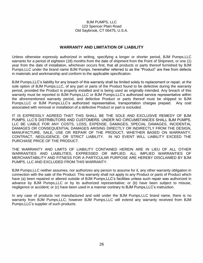
WARRANTY AND LIMITATION OF LIABILITY
Unless otherwise expressly authorized in writing, specifying a longer or shorter period, BJM Pumps,LLC warrants for a period of eighteen (18) months from the date of shipment from the Point of Shipment, or one (1) year from the date of installation, whichever occurs first, that all products or parts thereof furnished by BJM Pumps,LLC under the brand name BJM Pumps, hereinafter referred to as the “Product” are free from defects in materials and workmanship and conform to the applicable specification. BJM Pumps,LLC’s liability for any breach of this warranty shall be limited solely to replacement or repair, at the sole option of BJM Pumps,LLC, of any part or parts of the Product found to be defective during the warranty period, provided the Product is properly installed and is being used as originally intended. Any breach of this warranty must be reported to BJM Pumps,LLC or BJM Pumps,LLC’s authorized service representative within the aforementioned warranty period, and defective Product or parts thereof must be shipped to BJM Pumps,LLC or BJM Pumps,LLC’s authorized representative, transportation charges prepaid. Any cost associated with removal or installation of a defective Product or part is excluded. IT IS EXPRESSLY AGREED THAT THIS SHALL BE THE SOLE AND EXCLUSIVE REMEDY OF BJM PUMPS, LLC’S DISTRIBUTORS AND CUSTOMERS. UNDER NO CIRCUMSTANCES SHALL BJM PUMPS, LLC BE LIABLE FOR ANY COSTS, LOSS, EXPENSE, DAMAGES, SPECIAL DAMAGES, INCIDENTAL DAMAGES OR CONSEQUENTIAL DAMAGES ARISING DIRECTLY OR INDIRECTLY FROM THE DESIGN, MANUFACTURE, SALE, USE OR REPAIR OF THE PRODUCT, WHETHER BASED ON WARRANTY, CONTRACT, NEGLIGENCE, OR STRICT LIABILITY. IN NO EVENT WILL LIABILITY EXCEED THE PURCHASE PRICE OF THE PRODUCT. THE WARRANTY AND LIMITS OF LIABILITY CONTAINED HEREIN ARE IN LIEU OF ALL OTHER WARRANTIES AND LIABILITIES, EXPRESSED OR IMPLIED. ALL IMPLIED WARRANTIES OF MERCHANTABILITY AND FITNESS FOR A PARTICULAR PURPOSE ARE HEREBY DISCLAIMED BY BJM PUMPS, LLC AND EXCLUDED FROM THIS WARRANTY. BJM Pumps,LLC neither assumes, nor authorizes any person to assume for it, any other warranty obligation in connection with the sale of the Product. This warranty shall not apply to any Product or parts of Product which have (a) been repaired or altered outside of BJM Pumps,LLC’s facilities unless such repair was authorized in advance by BJM Pumps,LLC or by its authorized representative; or (b) have been subject to misuse, negligence or accident; or (c) have been used in a manner contrary to BJM Pumps,LLC’s instruction. In any case of products not manufactured and sold under the BJM Pumps,LLC brand name, there is no warranty from BJM Pumps,LLC; however BJM Pumps,LLC will extend any warranty received from BJM Pumps,LLC’s supplier of such products.
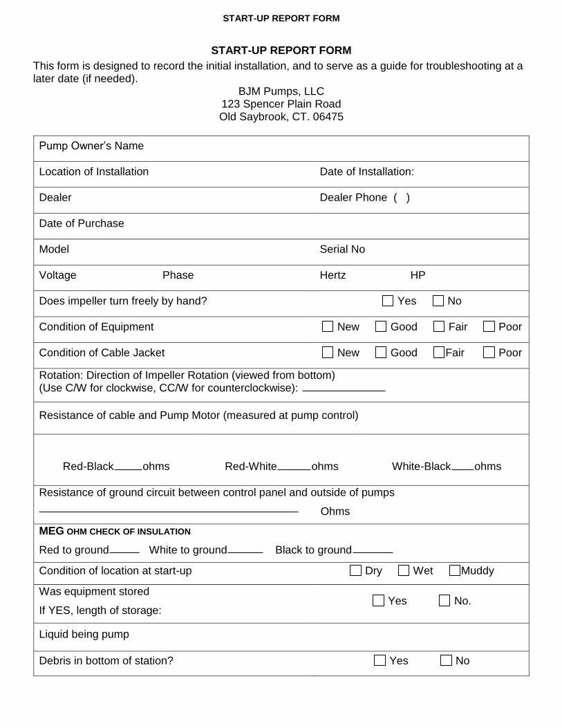
START-UP REPORT FORM
START-UP REPORT FORM
This form is designed to record the initial installation, and to serve as a guide for troubleshooting at a later date (if needed).
BJM Pumps, LLC 123 Spencer Plain Road Old Saybrook, CT. 06475
Pump Owner’s Name
Location of Installation Date of Installation:
Dealer Dealer Phone ( )
Date of Purchase
Model Serial No
Voltage Phase Hertz HP
Does impeller turn freely by hand? Yes No
Condition of Equipment New Good Fair Poor
Condition of Cable Jacket New Good Fair Poor
Rotation: Direction of Impeller Rotation (viewed from bottom) (Use C/W for clockwise, CC/W for counterclockwise):
Resistance of cable and Pump Motor (measured at pump control)
Red-Black ohms
Red-White ohms
White-Black ohms
Resistance of ground circuit between control panel and outside of pumps
Ohms
MEG OHM CHECK OF INSULATION
Red to ground White to ground Black to ground
Condition of location at start-up Dry Wet Muddy
Was equipment stored
If YES, length of storage: Yes No.
Liquid being pump
Debris in bottom of station? Yes No
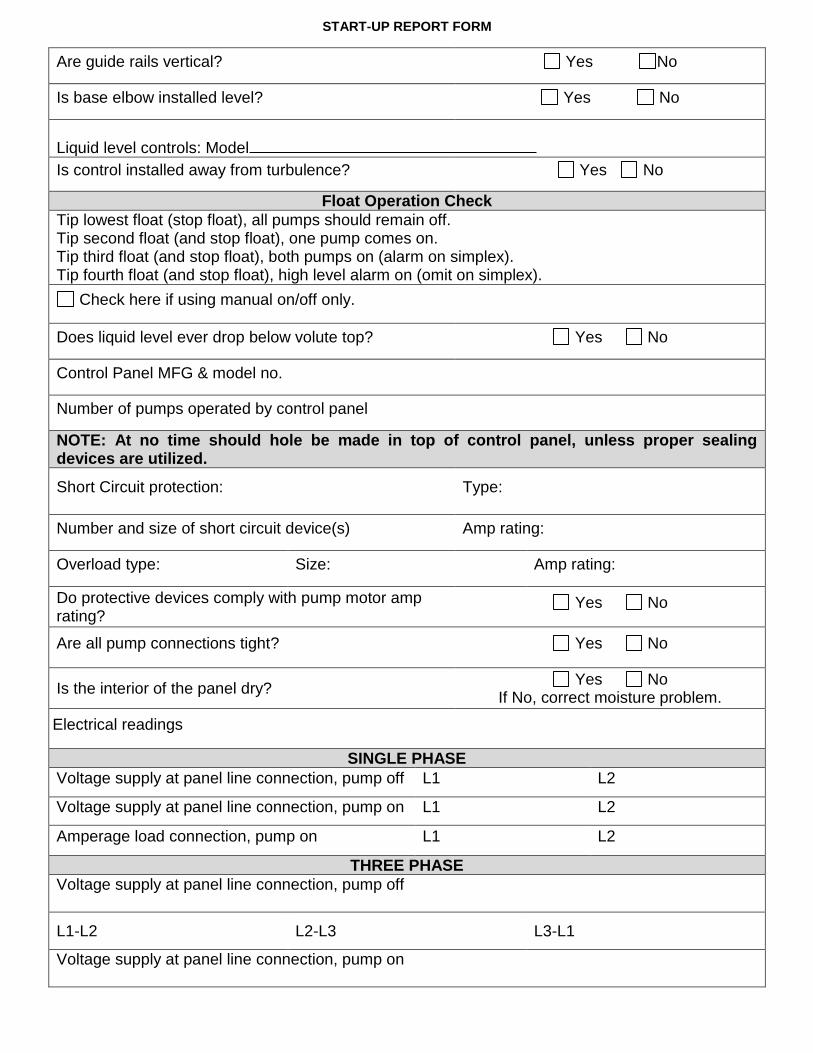
START-UP REPORT FORM
Are guide rails vertical? Yes No
Is base elbow installed level? Yes No
Liquid level controls: Model
Is control installed away from turbulence? Yes No
Float Operation Check
Tip lowest float (stop float), all pumps should remain off. Tip second float (and stop float), one pump comes on. Tip third float (and stop float), both pumps on (alarm on simplex). Tip fourth float (and stop float), high level alarm on (omit on simplex).
Check here if using manual on/off only.
Does liquid level ever drop below volute top? Yes No
Control Panel MFG & model no.
Number of pumps operated by control panel
NOTE: At no time should hole be made in top of control panel, unless proper sealing devices are utilized.
Short Circuit protection: Type:
Number and size of short circuit device(s) Amp rating:
Overload type: Size: Amp rating:
Do protective devices comply with pump motor amp rating?
Yes No
Are all pump connections tight? Yes No
Is the interior of the panel dry? Yes No
If No, correct moisture problem.
Electrical readings
SINGLE PHASE
Voltage supply at panel line connection, pump off L1 L2
Voltage supply at panel line connection, pump on L1 L2
Amperage load connection, pump on L1 L2
THREE PHASE
Voltage supply at panel line connection, pump off
L1-L2 L2-L3 L3-L1
Voltage supply at panel line connection, pump on
START-UP REPORT FORM
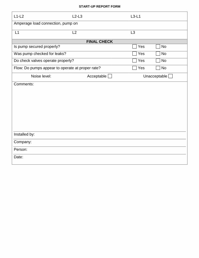
L1-L2 L2-L3 L3-L1
Amperage load connection, pump on
L1 L2 L3
FINAL CHECK
Is pump secured properly? Yes No
Was pump checked for leaks? Yes No
Do check valves operate properly? Yes No
Flow: Do pumps appear to operate at proper rate? Yes No
Noise level: Acceptable Unacceptable
Comments:
Installed by:
Company:
Person:
Date:

NOTES:

BJM Pumps is a registered trademark of BJM Pumps, LLC. Version 9/23/2014 Copyright © 2013 BJM Pumps, LLC. All rights reserved.
Note: This manual requires factory mutual approval prior to issuing changes.
123 Spencer Plain Road • PO Box 1138 • Old Saybrook, CT 06475, USA • Phone: (860) 399-5937 • Fax: (860) 399-7784
Email: [email protected] • Web Site: www.bjmpumps.com