Embed Size (px)
Citation preview

IMPORTANT!DO NOT DESTROY
Installation, Operation, & Maintenance Manual
Month Year
Gorbel® Dealer
Date
Freestanding Motorized Jib Crane
Gorbel® Customer Order No. / Serial No.
®

TABLE OF CONTENTS
Introduction.........................................................................................................1
Instructions. Step.1. -.Pre-Assembly............................................................................................... 2.
. Step.2. -.Mast.Installation........................................................................................ 3-4
. Step.3. -.Head.Installation........................................................................................... 5
. Step.4. -.Boom.Installation.......................................................................................... 6
. Step.5. -.Drive.Installation........................................................................................ 7-8
. Step.6. -.Electrification.Installation......................................................................... 9-12
. Step.7. -.Final.Steps................................................................................................. 13
Shut-Down.Instructions.................................................................................... 13
Safety.Warnings.and.Precautions.................................................................... 13
Trouble.Shooting.Guide................................................................................... 14
Hardware.Torque.Chart................................................................................... 14
Spare.Parts.List................................................................................................ 15
Crane.Operator.Instructions............................................................................. 16
General.Safety.Suggestions............................................................................ 16
Limited.Warranty.............................................................................................. 17
Maintenance.Schedule..................................................................................... 18
Lubrication.Schedule........................................................................................ 18
Specifications,.Drawings.&.Literature.(Inserted.in.this.manual.when.applicable). Specification.Sheet
. General.Arrangement.Drawing
. Drive.Assembly.Drawing
. Electrical.Schematic
. Pendant.Wiring.Schematic
. Acceleration.Control.Module.(ACM)
. Friction.Clutch
. Speed.(Gear).Reducer
Questions?.Concerns?.Comments?.Please.call.(800).821-0086.(US.and.Canada).or(585).924-6262.(outside.US).
10/10®
INTRODUCTIONThank.you.for.choosing.a.Gorbel®.Free.Standing.Jib.Crane.to.solve.your.material.handling.needs...The.innovative.design.and.heavy.duty.construction.of.the.Gorbel®.Free.Standing.Jib.Crane.will.provide.a.superior.quality.product.that.will.offer.years.of.long.term.value...All.Gorbel®.cranes.are.pre-engineered.for.powered.hoist.operation...The.hoist.weight.allowance.is.15%.of.the.crane.capacity.(for.example,.a.crane.rated.for.1000.pounds.allows.for.a.1000.pound.live.load.plus.150.pounds.for.the.weight.of.the.hoist)...There.is.also.an.allowance.of.25%.of.the.cranecapacity.for.impact.caused.by.hoist.use...Gorbel®.Free.Standing.Jib.Cranes.will.provide.many.years.of.dependable.service.by.following.the.installation.and.maintenance.procedures.described.herein.
Dimensions contained in this installation manual are for reference only and may differ for your particular application. Please refer to the enclosed General Arrangement Drawing for actual dimensions.
Normal safety precautions:..These.include,.but.are.not.limited.to:•. Checking.for.obstructions.in.crane.rotation•. Checking.that.all.bolts.are.tight.and.have.lockwashers•. Making.sure.that.endstop.is.in.place•. Making.sure.that.festooning.cannot.be.snagged.or.pinched
For.additional.safety.precautions,.see.page.16.
WARNINGOnly.competent.erection.personnel.familiar.with.standard.fabrication.practices.should.be.employed.to.assemble.these.cranes.because.of.the.necessity.of.properly.interpreting.these.instructions...Gorbel.is.not.responsible.for.the.quality.of.workmanship.employed.in.the.installation.of.a.crane.according.to.these.instructions...Contact.Gorbel,.Inc.,.at.600.Fishers.Run,.P.O..Box.593,.Fishers,.New.York..14453-0593,.1-585-924-6262,.for.any.additional.information.if.necessary.
WARNINGEquipment.described.herein.is.not.designed.for,.and.should.not.be.used.for,.lifting,.supporting.or.transporting.humans...Failure.to.comply.with.any.one.of.the.limitations.noted.herein.can.result.in.serious.bodily.injury.and/or.property.damage...Check.State.and.Local.regulations.for.additional.requirements.
WARNINGConsult.a.qualified.structural.engineer.to.determine.if.your.support.structure.is.adequate.to.support.the.loadsgenerated.by.anchor.bolt.force,.overturning.moment,.or.axial.load.of.your.crane.
WARNINGCrane.cannot.be.utilized.as.a.ground:..A.separate.ground.wire.is.required...For.example,.systems.with.3-phase.power.require.3.conductors.plus.one.ground.wire.
WARNINGReference.American.Institute.of.Steel.Construction.(AISC).manual.of.Steel.Construction.(9th.edition),.Part.5,.Specification.for.Structural.Joints.using.ASTM.A325.or.A490.Bolts.(section.8.d.2).for.proper.procedures.to.follow.when.using.any.torque.tightening.method.
WARNINGDo.not.field.modify.crane.in.any.way...Any.modifications.without.the.written.consent.of.Gorbel,.Inc..will.voidwarranty.
1 ®10/10

INSTALLATIONSTEP 1 - PRE-ASSEMBLY
1.1. Read.entire.manual.before.installing.the.crane.1.2. Check.packing.list.to.ensure.no.parts.have.been.lost.prior.to.initiating.assembly.of.crane.1.3. Tools.and.materials.typically.needed.to.assemble.crane:. . •.Torque.wrench. . . •.Ladders/man.lifts. . •.Hand.tools. . . . •.Leveling.tools.(plumb.bob,.plumb.fixture-pg..4). . •.Allen.wrenches. . . •.Lifting.device.to.lift.heavy.masts.and.booms. . •.Steel.shims.. . . •.Grout.(Non-Shrink.Precision.Grout). . •.Base.Plate.Template. . •.Anchor.Bolts.(grade.5.or.better)1.4. Identify.crane.type:
.If.your.crane.looks.like:
TIP:..Packing.list.can.be.found.in.plastic.pocket.attached.to.hardware.box..General.Arrangement.Drawing.can.be.found.inserted.in.this.installation.manual.
WARNINGConsult.a.qualified.structural.engineer.to.determine.that.your.support.structure.is.adequate.to.support.the.loads.generated.by.anchor.bolt.force,.overturning.moment,.or.axial.load.of.your.crane.
Go.to.step.2.1 Go.to.step.2.4 Go.to.step.2.7
Chart 1A. .Boom data.
STANDARD BOOM DATABoom.
Height.(W) Beam.Size Flange.Width.(in)
6” [email protected]#/ft. 3-3/8”8” [email protected]#/ft. 5-1/4”10” [email protected]#/ft. 4-5/8”12” [email protected]#/ft. 5”16” W16@45#/ft. 7”18” W18@50#/ft. 7-1/2”21” W21@62#/ft. 8-1/4”24” W24@84#/ft. 9”
2 10/10®
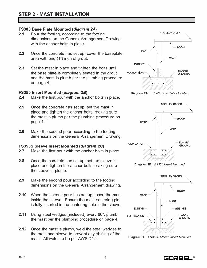
STEP 2 - MAST INSTALLATION
FS300 Base Plate Mounted (diagram 2A)2.1. Pour.the.footing,.according.to.the.footing. dimensions.on.the.General.Arrangement.Drawing,. with.the.anchor.bolts.in.place.
2.2. Once.the.concrete.has.set.up,.cover.the.baseplate. area.with.one.(1”).inch.of.grout.
2.3. Set.the.mast.in.place.and.tighten.the.bolts.until. the.base.plate.is.completely.seated.in.the.grout. and.the.mast.is.plumb.per.the.plumbing.procedure. on.page.4.
FS350 Insert Mounted (diagram 2B)2.4. Make.the.first.pour.with.the.anchor.bolts.in.place.
2.5. Once.the.concrete.has.set.up,.set.the.mast.in. place.and.tighten.the.anchor.bolts,.making.sure. the.mast.is.plumb.per.the.plumbing.procedure.on. page.4.
2.6. Make.the.second.pour.according.to.the.footing. dimensions.on.the.General.Arrangement.Drawing.
FS350S Sleeve Insert Mounted (diagram 2C)2.7. Make.the.first.pour.with.the.anchor.bolts.in.place.
2.8. Once.the.concrete.has.set.up,.set.the.sleeve.in. place.and.tighten.the.anchor.bolts,.making.sure. the.sleeve.is.plumb.
2.9. Make.the.second.pour.according.to.the.footing. dimensions.on.the.General.Arrangement.drawing.
2.10. When.the.second.pour.has.set.up,.insert.the.mast. inside.the.sleeve...Ensure.the.mast.centering.pin. is.fully.inserted.in.the.centering.hole.in.the.sleeve.
2.11. Using.steel.wedges.(included).every.60°,.plumb. the.mast.per.the.plumbing.procedure.on.page.4.
2.12. Once.the.mast.is.plumb,.weld.the.steel.wedges.to. the.mast.and.sleeve.to.prevent.any.shifting.of.the. mast...All.welds.to.be.per.AWS.D1.1.
Diagram 2A.. FS300 Base Plate Mounted.
Diagram 2B...FS350 Insert Mounted.
Diagram 2C. FS350S Sleeve Insert Mounted.
310/10 ®

STEP 2 - MAST INSTALLATION (CONTINUED)
Plumbing Procedure2.13. Drop.a.plumb.line.(not.included).from.the.top.of.the. mast,.using.the.fixture.(not.included).or.equivalent.as. shown.in.diagram 2D..Do not use a level to plumb the mast.
2.14. At.point.“A”,.one.(1”).inch.below.the.mast.top.plate,.set.. the.plumb.line.at.a.distance.of.three.(3”).inches.from.the.. surface.of.the.mast.pipe.(diagram 2E)..
2.15. At.point.“B”,.five.(5’).feet.below.point.“A”,. approximately.where.the.trunnion.rollers.will. contact.the.mast,.the.distance.between.the. plumb.line.and.the.face.of.the.mast.should.also. be.three.(3”).inches..This.is.a.plumb.situation..
2.16. Repeat.this.every.60°.to.ensure.the.mast.is. plumb.throughout.
Note:. Be.sure.to.fasten.plumb.line.securely.to.plumb.. fixture.so.that.it.will.not.move..Movement.will. result.in.an.inaccurate.plumb.measurement.
2.17. Once.mast.is.plumb.and.grout.(FS300).has. cured,.fully.tighten.anchor.bolt.hardware.
2.18. Verify.mast.is.still.plumb.
.TIP: .Be.sure.to.fasten.the.plumb.line.secure.to.a.plumb.fixture.(not.included).so.that.it.will
.not.move...Movement.will.result.in.an.inaccurate.plumb.measurement.
Diagram 2D. Plumbing fixture.
Diagram 2E. Plumbing the Mast.
DO NOT USE A LEVEL TOPLUMB THE MAST
4 10/10®
STEP 3 - HEAD INSTALLATION
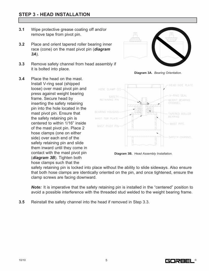
3.1. Wipe.protective.grease.coating.off.and/or. remove.tape.from.pivot.pin.
3.2. Place.and.orient.tapered.roller.bearing.inner. race.(cone).on.the.mast.pivot.pin.(diagram 3A).
3.3. Remove.safety.channel.from.head.assembly.if. it.is.bolted.into.place.
3.4. Place.the.head.on.the.mast.. Install.V-ring.seal.(shipped. loose).over.mast.pivot.pin.and. press.against.weight.bearing. frame..Secure.head.by. inserting.the.safety.retaining. pin.into.the.hole.located.in.the. mast.pivot.pin..Ensure.that. the.safety.retaining.pin.is. centered.to.within.1/16”.inside. of.the.mast.pivot.pin..Place.2. hose.clamps.(one.on.either. side).over.each.end.of.the. safety.retaining.pin.and.slide. them.inward.until.they.come.in. contact.with.the.mast.pivot.pin. (diagram 3B)..Tighten.both. hose.clamps.such.that.the. safety.retaining.pin.is.locked.into.place.without.the.ability.to.slide.sideways..Also.ensure. that.both.hose.clamps.are.identically.oriented.on.the.pin,.and.once.tightened,.ensure.the. clamp.screws.are.facing.downward.
Note:. It.is.imperative.that.the.safety.retaining.pin.is.installed.in.the.“centered”.position.to. avoid.a.possible.interference.with.the.threaded.stud.welded.to.the.weight.bearing.frame.
3.5. Reinstall.the.safety.channel.into.the.head.if.removed.in.Step.3.3.
Diagram 3A. Bearing Orientation.
510/10 ®
Diagram 3B. Head Assembly Installation.
STEP 4 - BOOM INSTALLATION
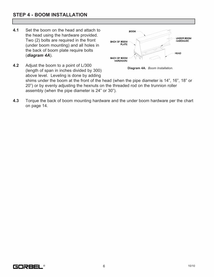
4.1. Set.the.boom.on.the.head.and.attach.to. the.head.using.the.hardware.provided.. Two.(2).bolts.are.required.in.the.front. (under.boom.mounting).and.all.holes.in. the.back.of.boom.plate.require.bolts. (diagram 4A).
4.2. Adjust.the.boom.to.a.point.of.L/300. (length.of.span.in.inches.divided.by.300). above.level...Leveling.is.done.by.adding. shims.under.the.boom.at.the.front.of.the.head.(when.the.pipe.diameter.is.14”,.16”,.18”.or. 20”).or.by.evenly.adjusting.the.hexnuts.on.the.threaded.rod.on.the.trunnion.roller. assembly.(when.the.pipe.diameter.is.24”.or.30”).
4.3. Torque.the.back.of.boom.mounting.hardware.and.the.under.boom.hardware.per.the.chart. on.page.14.
6 10/10®
Diagram 4A.. Boom Installation.
STEP 5 - DRIVE INSTALLATION
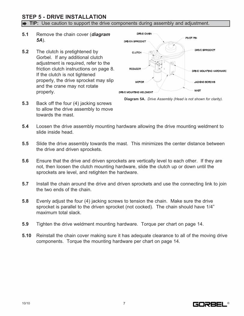
5.1. Remove.the.chain.cover.(diagram 5A).
5.2. The.clutch.is.pretightened.by. Gorbel...If.any.additional.clutch. adjustment.is.required,.refer.to.the. friction.clutch.instructions.on.page.8... If.the.clutch.is.not.tightened. properly,.the.drive.sprocket.may.slip. and.the.crane.may.not.rotate. properly.
5.3. Back.off.the.four.(4).jacking.screws. to.allow.the.drive.assembly.to.move. towards.the.mast.
5.4. Loosen.the.drive.assembly.mounting.hardware.allowing.the.drive.mounting.weldment.to. slide.inside.head.
5.5. Slide.the.drive.assembly.towards.the.mast...This.minimizes.the.center.distance.between. the.drive.and.driven.sprockets.
5.6. Ensure.that.the.drive.and.driven.sprockets.are.vertically.level.to.each.other...If.they.are. not,.then.loosen.the.clutch.mounting.hardware,.slide.the.clutch.up.or.down.until.the. sprockets.are.level,.and.retighten.the.hardware.
5.7. Install.the.chain.around.the.drive.and.driven.sprockets.and.use.the.connecting.link.to.join. the.two.ends.of.the.chain.
5.8. Evenly.adjust.the.four.(4).jacking.screws.to.tension.the.chain...Make.sure.the.drive. sprocket.is.parallel.to.the.driven.sprocket.(not.cocked)...The.chain.should.have.1/4”. maximum.total.slack.
5.9. Tighten.the.drive.weldment.mounting.hardware...Torque.per.chart.on.page.14.
5.10. Reinstall.the.chain.cover.making.sure.it.has.adequate.clearance.to.all.of.the.moving.drive. components...Torque.the.mounting.hardware.per.chart.on.page.14.
.TIP: .Use.caution.to.support.the.drive.components.during.assembly.and.adjustment.
Diagram 5A. Drive Assembly (Head is not shown for clarity).
710/10 ®
STEP 5 - DRIVE INSTALLATION (CONTINUED)
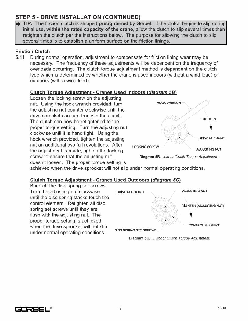
Friction Clutch5.11. During.normal.operation,.adjustment.to.compensate.for.friction.lining.wear.may.be. necessary...The.frequency.of.these.adjustments.will.be.dependent.on.the.frequency.of. overloads.occurring...The.clutch.torque.adjustment.method.is.dependent.on.the.clutch. type.which.is.determined.by.whether.the.crane.is.used.indoors.(without.a.wind.load).or. outdoors.(with.a.wind.load).
Clutch Torque Adjustment - Cranes Used Indoors (diagram 5B). Loosen.the.locking.screw.on.the.adjusting. nut...Using.the.hook.wrench.provided,.turn. the.adjusting.nut.counter.clockwise.until.the. drive.sprocket.can.turn.freely.in.the.clutch... The.clutch.can.now.be.retightened.to.the. proper.torque.setting...Turn.the.adjusting.nut. clockwise.until.it.is.hand.tight...Using.the. hook.wrench.provided,.tighten.the.adjusting. nut.an.additional.two.full.revolutions...After. the.adjustment.is.made,.tighten.the.locking. screw.to.ensure.that.the.adjusting.nut. doesn’t.loosen...The.proper.torque.setting.is. achieved.when.the.drive.sprocket.will.not.slip.under.normal.operating.conditions.
Clutch Torque Adjustment - Cranes Used Outdoors (diagram 5C). Back.off.the.disc.spring.set.screws... Turn.the.adjusting.nut.clockwise. until.the.disc.spring.stacks.touch.the. control.element...Retighten.all.disc. spring.set.screws.until.they.are. flush.with.the.adjusting.nut...The. proper.torque.setting.is.achieved. when.the.drive.sprocket.will.not.slip. under.normal.operating.conditions.
.TIP: .The.friction.clutch.is.shipped.pretightened.by.Gorbel...If.the.clutch.begins.to.slip.during
.initial.use,.within the rated capacity of the crane,.allow.the.clutch.to.slip.several.times.then. retighten.the.clutch.per.the.instructions.below...The.purpose.for.allowing.the.clutch.to.slip. several.times.is.to.establish.a.uniform.surface.on.the.friction.linings.
Diagram 5B. Indoor Clutch Torque Adjustment.
Diagram 5C. Outdoor Clutch Torque Adjustment.
8 10/10®

STEP 6 - ELECTRIFICATION INSTALLATION
Bottom Entry Collector Installation (diagram 6A)A). Remove.the.collector.cover,.the.safety. retaining.pin.and.o-rings.(2).B). Install.the.collector.adapter.pin.if.applicable. (positioned.inside.of.the.mast.pivot.pin).C). Secure.with.the.safety.retaining.pin.and. o-rings.(2).D). Place.the.bottom.entry.collector.on.top.of.the. adapter.pin.and.secure.with.the.set.screws.E). Terminate.the.incoming.power.wires.coming. up.through.the.mast.inside.the.collector.F). Terminate.the.outgoing.power.wires.to.the. control.panel.G).Reinstall.the.collector.cover.
Top Entry Collector Installation (diagram 6B)A). Position.the.collector.over.the.mounting.hole.pattern. on.top.of.the.boom.cap.channel.(or.mounting.plate. for.booms.without.a.cap.channel).B). Secure.with.the.mounting.hardware.provided.C). Terminate.the.incoming.power.wires.from.the.power. source.D). Terminate.the.outgoing.power.wires.from.the.control. panel.
Tagline Festoon Installation (diagram 6C)A). Place.the.hoist/hoist.trolley.(not. included).on.the.boom... Immediately.install.the. endstops.and.tagline.brackets. per.step.B.B). Attach.the.endstop.angles.and. tagline.brackets.to.the.boom. using.the.mounting.hardware. provided.C). Assemble.the.eyebolts.to.the. tagline.brackets.using.two.nuts. per.eyebolt.D). Loop.the.wire.rope.through.one. of.the.eyebolts.and.clamp.the. loop.using.a.cable.clamp... Repeat.this.step.at.the.other. eyebolt.while.removing.any.slack.from.the.wire.rope.E). Adjust.the.eyebolts.to.achieve.the.desired.cable.tension.and.lock.the.eyebolts.in.place.by. tightening.the.nuts.F). Run.the.festoon.cable.through.the.s-hooks.or.wire.rope.trolleys.G).Wire.both.the.jib.and.the.hoist.for.both.power.and.controls.
Diagram 6A. Bottom Entry Collector.
Diagram 6B. Top Entry Collector.
Diagram 6C. Tagline Festoon Installation.
910/10 ®

STEP 6 - ELECTRIFICATION INSTALLATION (CONTINUED)
JIB DRIVE CONTROLLERThe.drive.controller.for.the.jib.drive.is.pre-programmed.at.Gorbel.for.single.speed,.two.speed,.or.three.speedoperation...For.trouble.shooting.and.general.information,.a.brief.summary.of.how.the.drive.controller.is.designed.to.be.used.is.included.below...No.additional.programming.is.required...All.options.utilize.an.adjustable.speed.controller.
SINGLE SPEED OPTIONThis.option.utilized.the.drive.ratio.of.the.reducer.and.the.ratio.of.the.drive.to.driven.sprockets.to.produce.thestandard.jib.rotation.speed...These.ratios.are.determined.by.the.crane.parameters.(span,.capacity,.indoor,.outdoor,.etc.)...The.drive.controller.is.then.programmed.for.the.motor.to.operate.at.normal.speed.(60.Hz).
TWO SPEED OPTIONThis.option.varies.the.motor.speed.to.determine.the.desired.jib.drive.speeds...The.motor.controller.is.thenprogrammed.for.the.motor.to.operate.at.two.different.percentages.of.full.speed.based.on.the.desired.speedsspecified.by.the.customer.at.the.time.the.order.is.placed.
THREE SPEED OPTIONThis.option.is.similar.to.the.two.speed.option.listed.above...The.motor.controller.is.programmed.for.the.motor.to.operate.at.three.different.percentages.of.full.speed.based.on.the.desired.speeds.specified.by.the.customer.at.the.time.the.order.is.placed.
DRIVE CONTROLLER PROGRAMMINGGorbel.pre-programs.a.number.of.parameters.in.the.drive.controller.prior.to.shipment...The.remaining.parameters.are.left.at.the.factory.default.settings...All.parameters.are.stored.on.the.EPM.module...These.parameters.are.asfollows:
Preset.speeds.2.and.3.are.used.only.if.required.for.two.or.three.speed.drives.
Parameter.50.contains.the.fault.history.of.the.last.eight.(8).faults.with.the.most.recent.first...Pressing.the.“Mode”button.three.times.will.access.this.parameter.
Deceleration time: .The.deceleration.time.is.factory.set.at.4.seconds...This.can.be.adjusted.to.a.shorter.timeperiod.with.the.following.warning...If.the.deceleration.time.is.set.to.too.short.a.time.period,.the.drive.controller.will.shut.down.and.show.an.alarm...This.is.the.result.of.the.jib.crane.having.too.much.inertia.for.the.reducer.and.motor.to.stop.in.such.a.short.time...If.this.occurs,.increase.the.deceleration.time.
WARNINGThe.drive.controller.drive.must.only.see.its.own.internal.voltage.and.not.be.connected.to.an.external.voltage.source...Allowing.24.or.120.control.voltage.to.go.through.the.drive.will.PERMANENTLY.DAMAGE.the.internal.controls!
. TIP: The.two.or.three.speed.options.listed.above.consist.of.two.or.three.pre-set.speeds,.they.are.not.infinitely
. variable.during.use.
Parameter # Name - SCL/SLM Drive Name - SCF Drive New Value - (Setting)1 Line.Voltage Line.Voltage High.or.Low.(see.manual).-.(01)4 Stop.Method Stop.Method Ramp.to.Stop.-.(03)5 Standard.Speed.Source Standard.Speed.Source Preset.Speed.-.(02)10 TB-13A.Function.Select TB-13A.Function.Select Run.Reverse.-.(06)11 TB-13B.Function.Select TB-13B.Function.Select Preset.Speed.-.(04)12 TB-13E.Function.Select TB-13C.Function.Select Preset.Speed.-.(04)17 Rotation Rotation Forward.and.Reverse.-.(02)19 Acceleration Acceleration 4.Seconds20 Deceleration Deceleration 4.Seconds23 Minimum.Frequency Minimum.Frequency 0.Hz24 Maximum.Frequency Maximum.Frequency 60.Hz26 Motor.Overload Motor.Overload As.Required.(see.manual)31 Preset.Speed.1 Preset.Speed.1 As.Required.(0-60.Hz)32 Preset.Speed.2 Preset.Speed.2 As.Required.(0-60.Hz)36 Preset.Speed.3 Preset.Speed.3 As.Required.(0-60.Hz)
WARNINGDo.not.remove.or.install.the.EPM.module.while.power.is.applied.to.the.drive.controller...After.removing.power.from.the.drive.controller,.wait.three.(3).minutes.before.removing.the.EPM.module.for.the.capacitors.to.discharge.
10 10/10®
STEP 6 - ELECTRIFICATION INSTALLATION (CONTINUED)
LIMIT SWITCH INSTALLATIONIf.applicable,.install.limit.switches.per.the.following.instructions.and.diagram 6D,.page.12.
The.limit.switches.are.designed.to.shut.off.the.power.to.the.rotation.drive.motor.in.a.clockwise.or.counterclockwise.direction.and.are.not.to.serve.as.a.spotting.function.
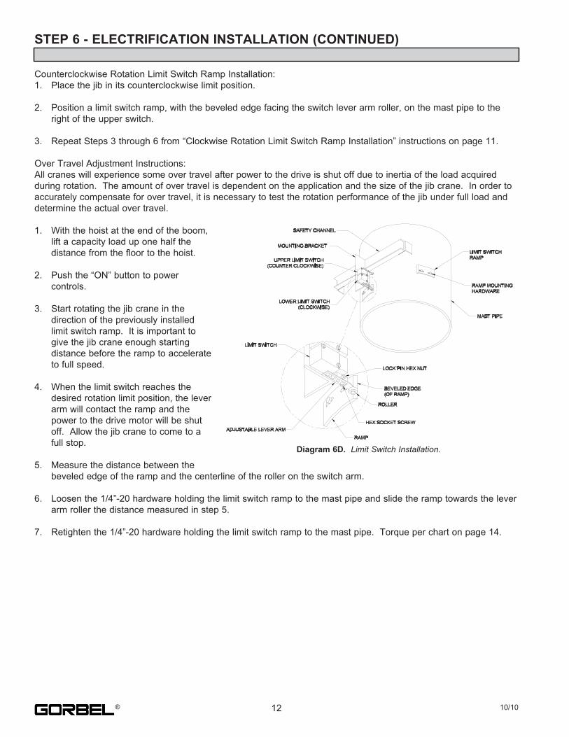
Two.limit.switches.are.mounted.on.the.safety.channel.at.the.rear.of.the.head.assembly...Each.switch.has.an.adjust-able.roller-type.lever.arm.and.is.actuated.by.a.limit.switch.ramp.which.must.be.attached.to.the.mast.pipe...The.limit.switch.ramps.must.be.field.located,.by.the.installer,.to.shut.off.power.at.the.desired.clockwise.andcounterclockwise.points...The.switches.are.prewired.into.the.control.panel.of.the.jib.crane.and.require.no.additional.electrical.hook-up.
SWITCH.ADJUSTMENT:After.the.jib.crane.has.been.erected.and.the.safety.channel,.with.the.two.limit.switches,.has.been.installed,.the.switch.set-up.is.as.follows:
1.. Loosen.the.hex.socket.screw.which.locks.the.adjustable.lever.arm.in.position.
2.. Loosen.the.lock.pin.hex.nut.which.fastens.the.lever.arm.assembly.to.the.limit.switch.
3.. Rotate.the.lever.arm.until.it.is.perpendicular.to.the.face.of.the.mast.pipe.and.then.rotate.it.an.additional.15°. away.from.the.side.which.will.contact.the.limit.switch.ramp.(15°.counterclockwise.for.the.upper.limit.switch.and. 15°.clockwise.for.the.lower.limit.switch)...The.additional.15°.will.prevent.jamming.of.the.lever.arm.when.the.lever. arm.contacts.the.limit.switch.ramp.
4.. Adjust.the.roller.so.that.it.has.an.1/8”.maximum.clearance.to.the.face.of.the.mast.pipe.
5.. Retighten.both.the.hex.socket.screw.and.the.lock.pin.hex.nut.
6.. Rotate.the.jib.crane.360°.and.check.to.see.if.the.roller.comes.in.contact.with.the.mast.pipe...If.the.roller.contacts. the.mast.pipe.increase.the.clearance.between.the.roller.and.the.pipe.until.it.does.not.
7.. Repeat.this.procedure.for.the.second.limit.switch.
RAMP.INSTALLATION:Two.rotation.limits.can.be.established,.one.in.the.clockwise.direction.and.one.in.the.counterclockwise.direction...The.lower.switch.will.be.the.clockwise.rotation.limit.switch.and.the.upper.switch.will.be.the.counterclockwise.rotation.limit.switch...Do not reverse the functions of the upper and lower limit switches...Reversing.the.functions.may.cause.the.limit.switch.lever.arm.to.hit.the.limit.switch.mounting.bracket.
Clockwise.Rotation.Limit.Switch.Ramp.Installation:1.. Place.the.jib.in.its.clockwise.limit.position.
2.. Position.a.limit.switch.ramp,.with.the.beveled.edge.facing.the.switch.lever.arm.roller,.on.the.mast.pipe.to.the.left. of.the.lower.switch.
3.. Slide.the.limit.switch.ramp.along.the.surface.of.the.mast.pipe,.into.the.roller.lever.arm,.causing.the.lever.arm.to. move...Stop.moving.the.ramp.when.an.audible.click.is.heard.from.the.switch.
4.. Drill.and.tap.(2).1/4”-20.holes.in.the.mast.pipe,.centered.in.the.two.slots.in.the.limit.switch.ramp.
5.. Secure.the.limit.switch.ramp.to.the.mast.pipe.using.the.(2).tapped.holes.and.the.1/4”-20.hardware.provided.
6.. Adjust.the.limit.switch.ramp.location.to.compensate.for.over.travel.(see.the.over.travel.adjustment.instructions. on.page.12).
1110/10 ®
STEP 6 - ELECTRIFICATION INSTALLATION (CONTINUED)
Counterclockwise.Rotation.Limit.Switch.Ramp.Installation:1.. Place.the.jib.in.its.counterclockwise.limit.position.
2.. Position.a.limit.switch.ramp,.with.the.beveled.edge.facing.the.switch.lever.arm.roller,.on.the.mast.pipe.to.the. right.of.the.upper.switch.
3.. Repeat.Steps.3.through.6.from.“Clockwise.Rotation.Limit.Switch.Ramp.Installation”.instructions.on.page.11.
Over.Travel.Adjustment.Instructions:All.cranes.will.experience.some.over.travel.after.power.to.the.drive.is.shut.off.due.to.inertia.of.the.load.acquiredduring.rotation...The.amount.of.over.travel.is.dependent.on.the.application.and.the.size.of.the.jib.crane...In.order.to.accurately.compensate.for.over.travel,.it.is.necessary.to.test.the.rotation.performance.of.the.jib.under.full.load.and.determine.the.actual.over.travel.
1.. With.the.hoist.at.the.end.of.the.boom,. lift.a.capacity.load.up.one.half.the. distance.from.the.floor.to.the.hoist.
2.. Push.the.“ON”.button.to.power. controls.
3.. Start.rotating.the.jib.crane.in.the. direction.of.the.previously.installed. limit.switch.ramp...It.is.important.to. give.the.jib.crane.enough.starting. distance.before.the.ramp.to.accelerate. to.full.speed.
4.. When.the.limit.switch.reaches.the. desired.rotation.limit.position,.the.lever. arm.will.contact.the.ramp.and.the. power.to.the.drive.motor.will.be.shut. off...Allow.the.jib.crane.to.come.to.a. full.stop.
5.. Measure.the.distance.between.the. beveled.edge.of.the.ramp.and.the.centerline.of.the.roller.on.the.switch.arm.
6.. Loosen.the.1/4”-20.hardware.holding.the.limit.switch.ramp.to.the.mast.pipe.and.slide.the.ramp.towards.the.lever. arm.roller.the.distance.measured.in.step.5.
7.. Retighten.the.1/4”-20.hardware.holding.the.limit.switch.ramp.to.the.mast.pipe...Torque.per.chart.on.page.14.
Diagram 6D. Limit Switch Installation.
12 10/10®
STEP 7 - FINAL STEPS
7.1.. Check.to.make.sure.all.bolts.are.tightened.and.lockwashers.are.compressed.
7.2.. If.necessary,.touch.up.with.paint.provided.
7.3.. Keep.Packing.List,.Installation.Manual,.General.Arrangement.Drawing.and.any.other. . inserts.together.in.a.safe.place.
SHUT-DOWN INSTRUCTIONS
Whenever.the.operator.leaves.the.crane,.this.procedure.should.be.followed:. 1.. Raise.all.hooks.to.an.intermediate.position.. 2.. Spot.the.crane.at.an.approved.designated.location.. 3.. Secure.the.beam.in.the.shut-down.position.or.storage.area...If.the.crane.is.an.outdoor. . application.and.it.has.a.tie.down.loop,.secure.tightly.especially.in.high.wind.areas.. 4.. Check.the.crane,.hoist.and.hook.storage.positions.to.be.sure.there.is.no.interference.with. . other.pieces.of.equipment.that.may.be.operating.in.the.area.. 5.. Place.all.controls.in.the.“OFF”.position.. 6.. Open.the.main.switch.to.the.“OFF”.position.. 7.. Make.a.visual.check.before.leaving.the.crane.
SAFETY WARNINGS AND PRECAUTIONS
Safety.is.very.important.when.operating.a.jib.crane...There.are.many.safety.warnings.andprecautions.the.operator.should.be.aware.of...These.include,.but.are.not.limited.to,.the.following:•. The.jib.can.only.be.used.to.pick.up.a.MAXIMUM.of.its.RATED CAPACITY.•. The.load.will.swing.when.lifted.•. Make.sure.the.power.is.“OFF”.prior.to.doing.any.electrical.work.or.checking.wires.and. connections.•. When.loading,.pick.load.directly.up...Crane.should.not.be.used.to.pick.up.a.load.diagonally.or. out.of.the.range.of.the.span.•. On.all.baseplate.mounted.cranes,.periodically.check.anchor.bolts.to.make.sure.they.are.tight.•. Watch.for.wet.spots:..oil,.water,.etc..where.they.operator.may.slip.•. Check.that.all.bolts.are.tight.and.have.lockwashers.•. Make.sure.endstops.are.in.place,.are.fully.engaging.the.trolley.and.the.endstop.hardware.is. tight.•. Make.sure.that.festooning.cannot.be.snagged.or.pinched.•. Check.for.obstructions.in.crane.travel.•. The.operator.should.have.full.concentration.on.the.crane.and.its.surroundings.at.all.times.
.TIP: .Do.not.throw.away.this.manual:.maintenance.schedule.is.on.back.cover.
WARNINGAny.changes.in.rolling.effort.or.unusual.noises.must.be.immediately.identified.and.corrected.
1310/10 ®

TROUBLE SHOOTING GUIDE
If.you.are.experiencing.any.other.problems.in.the.start-up.or.operation.of.your.Gorbel®.crane.please.call.800-821-0086.and.ask.for.Customer.Service.
HARDWARE TORQUE CHART
PROBLEM CHECK YES NOJib.does.not.rotate
1.. Is.AC.contactor.coil.pulling.in. when.ON.is.pressed.and.does.it. stay.in?
2.. Is.motor.shaft.turning?..(With. TEFC.motors,.if.fan.is.blowing.air,. motor.shaft.is.turning.)3.. Does.shaft.or.drive.reducer.turn?4.. Is.the.EPM.module.installed.in.the. drive.controller?
5.. Is.the.drive.controller.showing.an. error.code?6.. Call.factory.and.ask.for.Customer. Service.
See.No..2
See.No..3
See.No..4See.No..5
See.No..6.and.note.the.error.
Check.fuses.in.jib.panel...Check.Pendant.wiring...Check.control.transformer.fuse...Check.that.the.drive.is.not.showing.an.alarm.Check.that.motor.leads.are.secure.
Tighten.clutch.(see.page.8).Install.the.EPM.module.(see.page.8).and.ensure.that.it.is.completely.seated.in.the.drive.unit.
Jib.rotates.in.one.direction.only
1.. Check.pendant.wiring.2.. Is.clutch.properly.adjusted?3.. Call.factory.and.ask.for.Customer. Service.
See.No..2See.No..3
Tighten.clutch.(see.page.8).
HARDWARE.TORQUEHARDWARE.SIZE UNPLATED.FINISH PLATED.FINISH
1/4”-20 8.FT-LBS 6-1/3.FT-LBS3/8”-16 31.FT-LBS 23.FT-LBS1/2”-13 76.FT-LBS 57.FT-LBS5/8”-11 150.FT-LBS 112.FT-LBS3/4”-10 266.FT-LBS 200.FT-LBS7/8”-9 430.FT-LBS 322.FT-LBS
14 10/10®
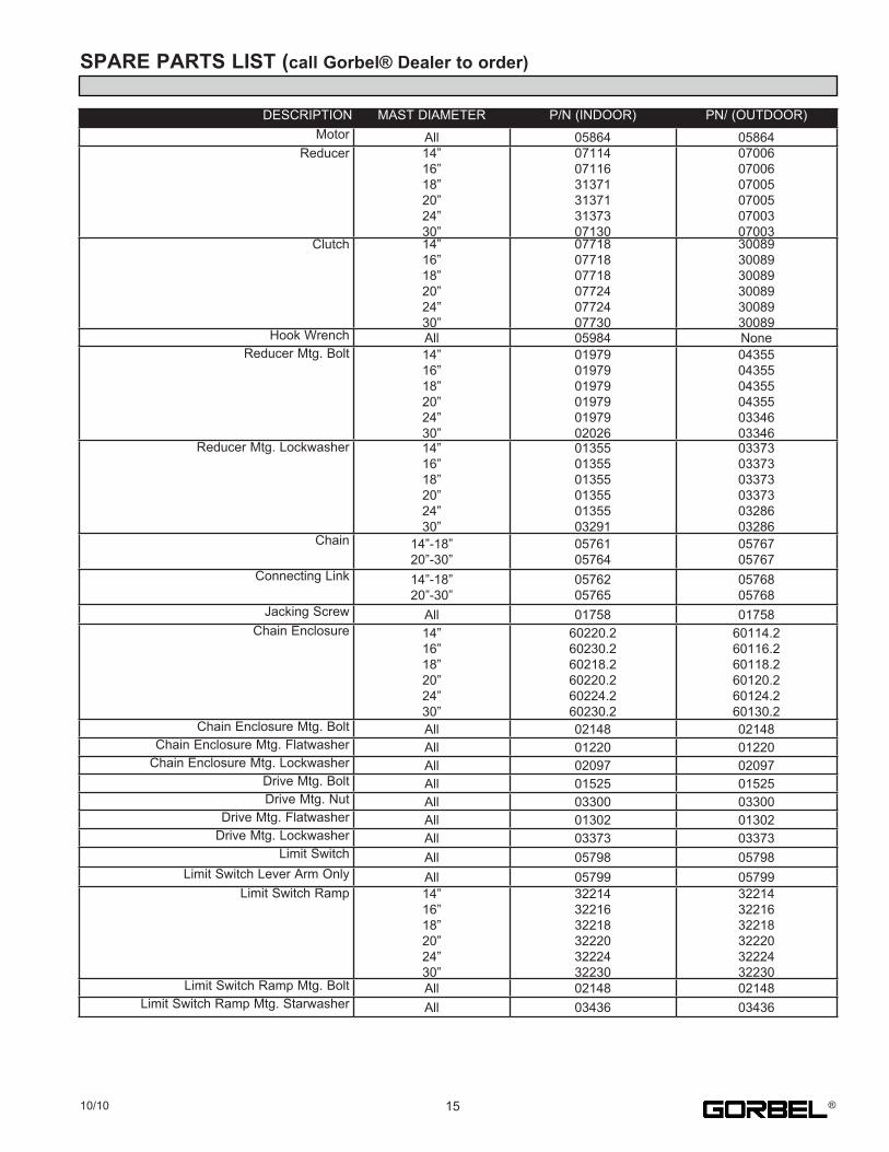
SPARE PARTS LIST (call Gorbel® Dealer to order)
DESCRIPTION MAST.DIAMETER P/N.(INDOOR) PN/.(OUTDOOR)Motor All 05864 05864
Reducer 14”16”18”20”24”30”
071140711631371313713137307130
070060700607005070050700307003
Clutch 14”16”18”20”24”30”
077180771807718077240772407730
300893008930089300893008930089
Hook.Wrench All 05984 NoneReducer.Mtg..Bolt 14”
16”18”20”24”30”
019790197901979019790197902026
043550435504355043550334603346
Reducer.Mtg..Lockwasher 14”16”18”20”24”30”
013550135501355013550135503291
033730337303373033730328603286
Chain 14”-18”20”-30”
0576105764
0576705767
Connecting.Link 14”-18”20”-30”
0576205765
0576805768
Jacking.Screw All 01758 01758Chain.Enclosure 14”
16”18”20”24”30”
60220.260230.260218.260220.260224.260230.2
60114.260116.260118.260120.260124.260130.2
Chain.Enclosure.Mtg..Bolt All 02148 02148Chain.Enclosure.Mtg..Flatwasher All 01220 01220Chain.Enclosure.Mtg..Lockwasher All 02097 02097
Drive.Mtg..Bolt All 01525 01525Drive.Mtg..Nut All 03300 03300
Drive.Mtg..Flatwasher All 01302 01302Drive.Mtg..Lockwasher All 03373 03373
Limit.Switch All 05798 05798Limit.Switch.Lever.Arm.Only All 05799 05799
Limit.Switch.Ramp 14”16”18”20”24”30”
322143221632218322203222432230
322143221632218322203222432230
Limit.Switch.Ramp.Mtg..Bolt All 02148 02148Limit.Switch.Ramp.Mtg..Starwasher All 03436 03436
1510/10 ®
CRANE OPERATOR INSTRUCTIONS
Overhead.cranes.and.jib.cranes.generally.handle.materials.over.working.areas.where.there.are.personnel...Therefore,.it.is.important.for.the.Crane.Operator.to.be.instructed.in.the.use.of.the.crane.and.to.understand.the.severe.consequences.of.careless.operation.It.is.not.intended.that.these.suggestions.take.precedence.over.existing.plant.safety.rules.and.regulations.or.OSHA.regulations...However,.a.thorough.study.of.thefollowing.information.should.provide.a.better.understanding.of.safe.operation.and.afford.a.greater.margin.of.safety.for.people.and.machinery.on.the.plant.floor.It.must.be.recognized.that.these.are.suggestions.for.the.Crane.Operator’s.use...It.is.the.responsibility.of.the.owner.to.make.personnel.aware.of.all.federal,.state.and.local.rules.and.codes,.and.to.make.certain.operators.are.properly.trained.QualificationsCrane.operation,.to.be.safe.and.efficient,.requires.skill:..the.exercise.of.extreme.care.and.good.judgment,.alertness.and.concentration,.and.rigid.adherence.to.proven.safety.rules.and.practices.as.outlined.in.applicable.and.current.ANSI.and.OSHA.safety.standards...In.general.practice,.no.person.should.be.permitted.to.operate.a.crane:. •. Who.cannot.speak.the.appropriate.language.or.read.and.understand.the.printed.instructions.. •. Who.is.not.of.legal.age.to.operate.this.type.of.equipment.. •. Whose.hearing.or.eyesight.is.impaired.(unless.suitably.corrected.with.good.depth.perception).. •. Who.may.be.suffering.from.heart.or.other.ailments.which.might.interfere.with.the.operator’s.safe.performance.. •. Unless.the.operator.has.carefully.read.and.studied.this.operation.manual.. •. Unless.the.operator.has.been.properly.instructed.. •. Unless.the.operator.has.demonstrated.his.instructions.through.practical.operation.. •. Unless.the.operator.is.familiar.with.hitching.equipment.and.safe.hitching.equipment.practices.Handling the Jib Boom MotionBefore.using.the.boom.of.the.jib.crane,.the.operator.should.be.sure.the.hook.is.high.enough.to.clear.any.obstruction...Before.a.load.is.handled.by.the.crane,.the.jib.boom.should.be.brought.into.position.so.that.it.is.directly.over.the.load...Start.the.jib.boom.slowly.and.bring.it.up.to.speed.gradually...Approaching.the.place.where.it.is.desired.to.stop.the.jib,.reduce.the.boom.speed.Handling the Trolley MotionBefore.a.load.is.handled,.the.hoist.should.be.positioned.directly.over.the.load.that.is.to.be.handled...When.the.slack.is.taken.out.of.the.slings,.if.the.hoist.is.not.directly.over.the.load,.bring.it.directly.over.the.load.before.hoisting.is.continued...Failure.to.center.the.hoist.over.the.load.may.cause.the.load.to.swing.upon.lifting...Always.start.the.trolley.motion.slowly.and.reduce.the.trolley.speed.gradually.Handling the Hoist MotionRefer.to.the.lifting.(hoist).equipment’s.operating.instructions.
GENERAL SUGGESTIONSKnow Your CraneCrane.operators.should.be.familiar.with.the.principal.parts.of.a.crane.and.have.a.thorough.knowledge.of.crane.control.functions.and.movements...The.crane.operator.should.be.required.to.know.the.location.and.proper.operation.of.the.main.conductor.disconnecting.means.for.all.power.to.the.attachments.on.the.crane.ResponsibilityEach.crane.operator.should.be.held.directly.responsible.for.the.safe.operation.of.the.crane...Whenever.there.is.any.doubt.as.to.SAFETY,.the.crane.operator.should.stop.the.crane.and.refuse.to.handle.loads.until:..(1).safety.has.been.assured.or.(2).the.operator.has.been.ordered.to.proceed.by.the.supervisor,.who.then.assumes.all.responsibility.for.the.SAFETY.of.the.lift.Do.not.permit.ANYONE.to.ride.on.the.hook.or.a.load.InspectionTest.the.crane.movement.and.any.attachments.on.the.crane.at.the.beginning.of.each.shift...Whenever.the.operator.finds.anything.wrong.or.apparently.wrong,.the.problem.should.be.reported.immediately.to.the.proper.supervisor.and.appropriate.corrective.action.taken.Operating SuggestionsOne.measure.of.a.good.crane.operator.is.the.smoothness.of.the.crane.operation...The.good.crane.operator.should.know.and.follow.these.proven.suggestions.for.safe,.efficient.crane.handling.1.. The.crane.should.be.moved.smoothly.and.gradually.to.avoid.abrupt,.jerky.movements.of.the.load...Slack.must.be.removed.from.the.sling.and.hoisting.ropes. before.the.load.is.lifted.2.. Center.the.crane.over.the.load.before.starting.the.hoist.to.avoid.swinging.the.load.as.the.lift.is.started...Loads.should.not.be.swung.by.the.crane.to.reach.areas. not.under.the.crane.3.. Crane-hoisting.ropes.should.be.kept.vertical...Cranes.shall not.be.used.for.side.pulls.4.. Be.sure.everyone.in.the.immediate.area.is.clear.of.the.load.and.aware.that.a.load.is.being.moved.5.. Do.not.make.lifts.beyond.the.rated.load.capacity.of.the.crane,.sling.chains,.rope.slings,.etc.6.. Make.certain.that.before.moving.the.load,.load.slings,.load.chains,.or.other.lifting.devices.are.fully.seated.in.the.saddle.of.the.hook.with.hook.latch.closed.(if. equipped.with.hook.latch).7.. Check.to.be.sure.that.the.load.and/or.bottom.block.is.lifted.high.enough.to.clear.all.obstructions.when.moving.boom.or.trolley.8.. At.no.time.should.a.load.be.left.suspended.from.the.crane.unless.the.operator.has.the.push.button.with.the.power.on,.and.under.this.condition.keep.the.load.as. close.as.possible.to.the.floor.to.minimize.the.possibility.of.an.injury.if.the.load.should.drop...When.the.crane.is.holding.a.load,.the.crane.operator.should.remain. at.the.push.button.9.. Do.not.lift.loads.with.sling.hooks.hanging.loose...If.all.sling.hooks.are.not.needed,.they.should.be.properly.stored,.or.use.a.different.sling.10.. All.slings.or.cables.should.be.removed.from.the.crane.hooks.when.not.in.use.(dangling.cables.or.hooks.hung.in.sling.rings.can.inadvertently.snag.other.objects. when.the.crane.is.moving).11.. Operators.shall.not.carry.loads.and/or.empty.bottom.blocks.over.personnel...Particular.additional.caution.should.be.practiced.when.using.magnet.or.vacuum. devices...Loads,.or.parts.of.loads,.held.magnetically.could.drop...Failure.to.power.magnets.or.vacuum.devices.can.result.in.dropping.the.load...Extra.precaution. should.be.exercised.when.handling.molten.metal.in.the.proximity.of.personnel.12.. Whenever.the.operator.leaves.the.crane.the.following.procedure.should.be.followed:. . •. Raise.all.hooks.to.an.intermediate.position.. . •. Spot.the.crane.at.an.approved.designated.location.. . •. Place.all.controls.in.the.“off”.position.. . •. Open.the.main.switch.to.the.“off”.position.. . •. Make.visual.check.before.leaving.the.crane.13.. In.case.of.emergency.or.during.inspection,.repairing,.cleaning.or.lubrication,.a.warning.sign.or.signal.should.be.displayed.and.the.main.switch.should.be.locked. in.the.“off”.position...This.should.be.done.whether.the.work.is.being.done.by.the.crane.operator.or.by.others.14.. Contact.with.rotation.stops.or.trolley.end.stops.shall.be.made.with.extreme.caution...The.operator.should.do.so.with.particular.care.for.the.safety.of.persons. below.the.crane,.and.only.after.making.certain.that.any.persons.on.the.other.cranes.are.aware.of.what.is.being.done.15.. ANY.SAFETY.FEATURES.AND.MECHANISMS.BUILT-IN.OR.OTHERWISE.PROVIDED.WITH.THE.CRANE.BY.GORBEL.ARE.REQUIRED.FOR.THE.SAFE. OPERATION.OF.THE.CRANE...DO.NOT,.UNDER.ANY.CIRCUMSTANCES,.REMOVE.OR.OTHERWISE.IMPAIR.OR.DISABLE.THE.PROPER.FUNCTIONING. OF.ANY.CRANE.SAFETY.MECHANISMS.OR.FEATURES.BUILT-IN.OR.OTHERWISE.PROVIDED.BY.GORBEL.FOR.SAFE.OPERATION.OF.THE.CRANE.. ANY.REMOVAL,.IMPAIRMENT.OR.DISABLING.OF.ANY.SUCH.SAFETY.MECHANISMS.OR.FEATURES.OR.OTHER.USE.OR.OPERATION.OF.THE.CRANE. WITHOUT.THE.COMPLETE.AND.PROPER.FUNCTIONING.OF.ANY.SUCH.SAFETY.MECHANISMS.OR.FEATURES.AUTOMATICALLY.AND.IMMEDIATELY. VOIDS.ANY.AND.ALL.EXPRESS.AND.IMPLIED.WARRANTIES.OF.ANY.KIND.OR.NATURE.
. TIP:..Be.sure.your.installers,.maintenance.personnel,.and.operators.realize.this.jib.can.only.be.used.to.pick.up.a.maximum
. of.its.rated.capacity.
16 10/10®

LIMITED WARRANTYIt.is.agreed.that.the.equipment.purchased.hereunder.is.subject.to.the.following.LIMITED.warranty.and.no.other..Gorbel.Incorporated.(“Gorbel”).warrants.the.manual.push-pull.Work.Station.Cranes,.Jib.Crane,.and.Gantry.Crane.products.to.be.free.from.defects.in.material.or.workmanship.for.a.period.of.ten.years.or.20,000.hours.use.from.date.of.shipment...Gorbel.warrants.the.Motorized.Work.Station.Cranes.and.Jib.Crane.products.to.be.free.from.defects.in.material.or.workmanship.for.a.period.of.two.years.or.4,000.hours.use.from.the.date.of.shipment..Gorbel.warrants.the.G-Force®.and.Easy.Arm™.products.to.be.free.from.defects.in.material.orworkmanship.for.a.period.of.one.year.or.2,000.hours.use.from.the.date.of.shipment..This.warranty.does.not.cover.Gantry.Crane.wheels.This.warranty.shall.not.cover.failure.or.defective.operation.caused.by.operation.in.excess.of.recommended.capacities,.misuses,.negligence.or.accident,.and.alteration.or.repair.not.authorized.by.Gorbel..No.system.shall.be.field.modified.after.manufacture.without.the.written.authorization.of.Gorbel,.Inc..Any.field.modification.made.to.the.system.without.thewritten.authorization.of.Gorbel,.Inc..shall.void.Gorbel’s.warranty.obligation..OTHER.THAN.AS.SET.FORTH.HEREIN,.NO.OTHER.EXPRESS.WARRANTIES,.AND.NO.IMPLIED.WARRANTIES,.ORAL.OR.WRITTEN,.INCLUDING.BUT.NOT.LIMITED.TO.THE.WARRANTIES.OF.MERCHANTABILITY.OR.FITNESS.FOR.PARTICULAR.PURPOSE,.ARE.MADE.BY.GORBEL.WITH.RESPECT.TO.ITS.PRODUCTS.AND.ALL.SUCH.WARRANTIES.ARE.HEREBY.SPECIFICALLY.DISCLAIMED..GORBEL.SHALL.NOT.BE.LIABLE.UNDER.ANY.CIRCUMSTANCES.FOR.ANY.INCIDENTAL,.SPECIAL.AND/OR.CONSEQUENTIAL.DAMAGES.WHATSOEVER,.WHETHER.OR.NOT.FORESEEABLE,.INCLUDING.BUT.NOT.LIMITED.TO.DAMAGES.FOR.LOST.PROFITS.AND.ALL.SUCH.INCIDENTAL,.SPECIAL.AND/OR.CONSEQUENTIAL.DAMAGES.ARE.HEREBY.ALSO.SPECIFICALLY.DISCLAIMED..Gorbel’s.obligation.and.Purchaser’s.or.end.user’s.sole.remedy.under.thiswarranty.is.limited.to.the.replacement.or.repair.of.Gorbel’s.products.at.the.factory,.or.at.the.discretion.of.Gorbel,.at.a.location.designated.by.Gorbel...Purchaser.or.end.user.shall.be.solely.responsible.for.all.freight.and.transportation.costs.incurred.in.connection.with.any.warranty.work.provided.by.Gorbel.hereunder...Gorbel.will.not.be.liable.for.any.loss,.injury.or.damage.to.persons.or.property,.nor.for.damages.of.any.kind.resulting.from.failure.or.defective.operation.of.any.materials.or.equipmentfurnished.hereunder..Components.and.accessories.not.manufactured.by.Gorbel.are.not.included.in.this.warranty...Purchaser’s.or.end.user’s.remedy.for.components.and.accessories.not.manufactured.by.Gorbel.is.limited.to.and.determined.by.the.terms.and.conditions.of.the.warranty.provided.by.the.respective.manufacturers.of.such.components.and.accessories. A) DISCLAIMER OF IMPLIED WARRANTY OF MERCHANTABILITY. . . Gorbel.and.Purchaser.agree.that.any.claim.made.by.Purchaser.which.is.inconsistent.with.Gorbel’s.obligations.and.the.warranty.remedies. . . provided.with.Gorbel’s.products,.and.in.particular,.special,.incidental.and.consequential.damages,.are.expressly.excluded. B) DISCLAIMER OF IMPLIED WARRANTY OF FITNESS FOR PARTICULAR PURPOSE. . . Gorbel.and.Purchaser.agree.that.the.implied.warranty.of.fitness.for.particular.purpose.is.excluded.from.this.transaction.and.shall.not.apply.to. . . the.goods.involved.in.this.transaction. C) DISCLAIMER OF EXPRESS WARRANTY. . . Gorbel’s.agents,.or.dealer’s.agents,.or.distributor’s.agents.may.have.made.oral.statements.about.the.machinery.and.equipment.described.in. . . this.transaction..Such.statements.do.not.constitute.warranties,.and.Purchaser.agrees.not.to.rely.on.such.statements..Purchaser.also.agrees. . . that.such.statements.are.not.part.of.this.transaction. D) DISCLAIMER OF SPECIAL, INCIDENTAL AND CONSEQUENTIAL DAMAGES. . . Gorbel.and.Purchaser.agree.that.any.claim.made.by.Purchaser.which.is.inconsistent.with.Gorbel’s.obligations.and.the.warranty.remedies. . . provided.with.Gorbel’s.products,.and.in.particular,.special,.incidental.and.consequential.damages,.are.expressly.excluded. E) DEALER OR DISTRIBUTOR NOT AN AGENT. . . Gorbel.and.Purchaser.agree.that.Purchaser.has.been.put.on.notice.that.dealer.or.distributor.is.not.Gorbel’s.agent.in.any.respect.for.any. . . reason..Gorbel.and.Purchaser.also.agree.that.Purchaser.has.been.put.on.notice.that.dealer.or.distributor.is.not.authorized.to.incur.any. . . obligations.or.to.make.any.representations.or.warranties.on.Gorbel’s.behalf.other.than.those.specifically.set.forth.in.Gorbel’s.warranty.provided. . . in.connection.with.its.product. F) MERGER. . . This.warranty.agreement.constitutes.a.final.and.complete.written.expression.of.all.the.terms.and.conditions.of.this.warranty.and.is.a.complete. . . and.exclusive.statement.of.those.terms. G) PAINTING. . . Every.crane.(excluding.components).receives.a.quality.paint.job.before.leaving.the.factory..Unfortunately,.no.paint.will.protect.against.the. . . abuses.received.during.the.transportation.process.via.common.carrier..We.have.included.at.least.one.(1).twelve.ounce.spray.can.for.touchup. . . with.each.crane.ordered.(unless.special.paint.was.specified)..If.additional.paint.is.required,.contact.a.Gorbel®.Customer.Service. . . Representative.at.1-800-821-0086.or.1-585-924-6262.
Title and Ownership:. Title.to.the.machinery.and.equipment.described.in.the.foregoing.proposal.shall.remain.with.Gorbel.and.shall.not.pass.to.the.Purchaser.until.the.full.amount. herein.agreed.to.be.paid.has.been.fully.paid.in.cash.
Claims and Damages:. Unless.expressly.stated.in.writing,.goods.and.equipment.shall.be.at.Purchaser’s.risk.on.and.after.Seller’s.delivery.in.good.shipping.order.to.the.Carrier..Gorbel. shall.in.no.event.be.held.responsible.for.materials.furnished.or.work.performed.by.any.person.other.than.it.or.its.authorized.representative.or.agent.
Cancellations:. If.it.becomes.necessary.for.the.purchaser.to.cancel.this.order.wholly.or.in.part,.he.shall.at.once.so.advise.Gorbel.in.writing..Upon.receipt.of.such.written.notice. all.work.will.stop.immediately..If.the.order.entails.only.stock.items,.a.flat.restocking.charge.of.15%.of.the.purchase.price.will.become.due.and.payable.by. Purchaser.to.Gorbel..Items.purchased.specifically.for.the.canceled.order.shall.be.charged.for.in.accordance.with.the.cancellation.charges.of.our.supplier.plus. 15%.for.handling.in.our.factory..The.cost.of.material.and/or.labor.expended.in.general.fabrication.for.the.order.shall.be.charged.for.on.the.basis.of.total.costs.to. Gorbel.up.to.the.time.of.cancellation.plus.15%.
Returns:. No.equipment,.materials.or.parts.may.be.returned.to.Gorbel.without.express.permission.in.writing.to.do.so.
. Extra.Charge.Delay:.If.Purchaser.delays.or.interrupts.progress.of.Seller’s.performance,.or.causes.changes.to.be.made,.Purchaser.agrees.to.reimburse.Gorbel
. for.expense,.if.any,.incident.to.such.delay.
Changes and Alterations:. Gorbel.reserves.the.right.to.make.changes.in.the.details.of.construction.of.the.equipment,.as.in.its.judgment,.will.be.in.the.interest.of.the.Purchaser;.will.make. any.changes.in.or.additions.to.the.equipment.which.may.be.agreed.upon.in.writing.by.the.Purchaser;.and.Gorbel.is.not.obligated.to.make.such.changes.in. products.previously.sold.any.customer.
Third Party Action:. Should.Gorbel.have.to.resort.to.third.party.action.to.collect.any.amount.due.after.thirty.(30).days.from.date.of.invoice,.the.Purchaser.agrees.to.pay.collection. costs,.reasonable.attorney’s.fees,.court.costs.and.legal.interest.
OSHA Responsibilities:. Gorbel.agrees.to.fully.cooperate.with.Purchaser.in.the.design,.manufacture.or.procurement.of.safety.features.or.devices.that.comply.with.OSHA.regulations..In. the.event.additional.equipment.or.labor.shall.be.furnished.by.Gorbel,.it.will.be.at.prices.and.standard.rates.then.in.effect,.or.as.may.be.mutually.agreed.upon.at. the.time.of.the.additional.installation.
Equal Employment Opportunity: . Gorbel.agrees.to.take.affirmative.action.to.ensure.equal.employment.opportunity.for.all.job.applicants.and.employees.without.regard.to.race,.color,.age,. religion,.sex,.national.origin,.handicap,.veteran,.or.marital.status..Gorbel.agrees.to.maintain.non-segregated.work.facilities.and.comply.with.rules.and.regulations. of.the.Secretary.of.Labor.or.as.otherwise.provided.by.law.or.Executive.Order.
1710/10 ®
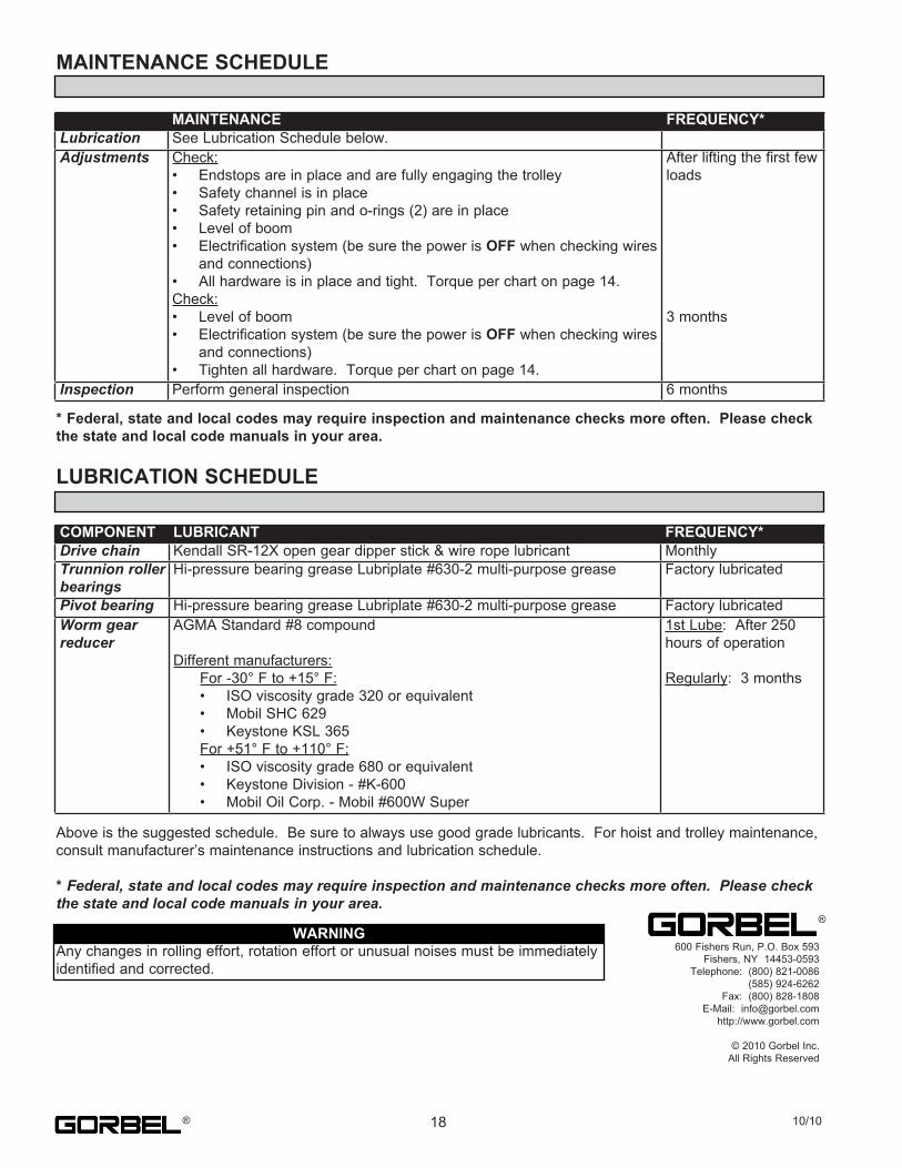
MAINTENANCE SCHEDULE
* Federal, state and local codes may require inspection and maintenance checks more often. Please check the state and local code manuals in your area.
LUBRICATION SCHEDULE
Above.is.the.suggested.schedule...Be.sure.to.always.use.good.grade.lubricants...For.hoist.and.trolley.maintenance,.consult.manufacturer’s.maintenance.instructions.and.lubrication.schedule.
* Federal, state and local codes may require inspection and maintenance checks more often. Please check the state and local code manuals in your area.
MAINTENANCE FREQUENCY*Lubrication See.Lubrication.Schedule.below.Adjustments Check:
•. Endstops.are.in.place.and.are.fully.engaging.the.trolley•. Safety.channel.is.in.place•. Safety.retaining.pin.and.o-rings.(2).are.in.place•. Level.of.boom•. Electrification.system.(be.sure.the.power.is.OFF.when.checking.wires. and.connections)•. All.hardware.is.in.place.and.tight...Torque.per.chart.on.page.14.Check:•. Level.of.boom•. Electrification.system.(be.sure.the.power.is.OFF.when.checking.wires. and.connections)•. Tighten.all.hardware...Torque.per.chart.on.page.14.
After.lifting.the.first.few.loads
3.months
Inspection Perform.general.inspection 6.months
COMPONENT LUBRICANT FREQUENCY*Drive chain Kendall.SR-12X.open.gear.dipper.stick.&.wire.rope.lubricant MonthlyTrunnion roller bearings
Hi-pressure.bearing.grease.Lubriplate.#630-2.multi-purpose.grease Factory.lubricated
Pivot bearing Hi-pressure.bearing.grease.Lubriplate.#630-2.multi-purpose.grease Factory.lubricatedWorm gear reducer
AGMA.Standard.#8.compound
Different.manufacturers:. For.-30°.F.to.+15°.F:. •. ISO.viscosity.grade.320.or.equivalent. •. Mobil.SHC.629. •. Keystone.KSL.365. For.+51°.F.to.+110°.F:. •. ISO.viscosity.grade.680.or.equivalent. •. Keystone.Division.-.#K-600. •. Mobil.Oil.Corp..-.Mobil.#600W.Super
1st.Lube:..After.250.hours.of.operation
Regularly:..3.months
600.Fishers.Run,.P.O..Box.593Fishers,.NY..14453-0593
Telephone:..(800).821-0086(585).924-6262
Fax:..(800).828-1808E-Mail:[email protected]
http://www.gorbel.com
©.2010.Gorbel.Inc.All.Rights.Reserved
®WARNING
Any.changes.in.rolling.effort,.rotation.effort.or.unusual.noises.must.be.immediately.identified.and.corrected.
18 10/10®