Embed Size (px)
Citation preview

IMPORTANT!DO NOT DESTROY
Installation, Operation, & Maintenance Manual
Month Year
Gorbel® Dealer
Date
Adjustable Height Aluminum Gantry Cranes
Gorbel® Customer Order No. / Serial No.
®
TABLE OF CONTENTS
Introduction ..........................................................................................................1-2
Installation Step 1 - Pre-assembly ..................................................................................................... 2-3
Step 2 - Crane Erection ................................................................................................... 3-4
Step 3 - Height Adjustment (with Optional Winches) ..........................................................5
Step 4 - Notes on Usage .....................................................................................................6
Step 5 - Final Steps .............................................................................................................6
General Layout Drawings ...................................................................................... 7
Crane Operator Instructions .................................................................................. 8
General Safety Suggestions.................................................................................. 8
Limited Warranty ................................................................................................... 9
Inspection and Maintenance Schedule ................................................................10
QUESTIONS? CONCERNS? COMMENTS? PLEASE CALL (800) 821-0086 (US and Canada) or (585) 924-6262 (outside US).
10/15
INTRODUCTIONThank you for choosing a Gorbel® Gantry Crane to solve your material handling needs. Theinnovative design and heavy-duty construction of Gorbel® Aluminum Gantry Cranes will provide a superior quality product. All Gorbel® cranes are pre-engineered for powered hoistoperation. The hoist weight allowance is 15% of the crane capacity (for example, a crane rated for 1000 pounds, allows for a 1000-pound live load plus 150 pounds for the weight of the hoist). There is also an allowance of 25% of the crane capacity for impact caused by hoist use. Gorbel® Gantry Cranes will provide many years of dependable service by following theinstallation and maintenance procedures described herein.
Dimensions contained in this installation manual are for reference only and may differ for your particular application. Please refer to the enclosed General Arrangement Drawing for actual dimensions.
Normal safety precautions: These include, but are not limited to:• Checking for obstructions in crane travel• Checking that all bolts are tight• Checking for any other unsafe conditions• For additional safety precautions, see page 8
WARNINGRead all instructions in this manual before assembling or using this equipment.
WARNING
WARNINGA load should be moved from one point to another by moving the trolley back and forth along the Gantry I-beam, while the Gantry Crane itself is stationary. Use EXTREME CAUTION, CENTER THE LOAD ON THE I-BEAM and LOWER THE LOAD AS MUCH AS POSSIBLE when attempting to horizontally move a load by moving the entire Gantry Crane; this is NOT RECOMMENDED.
WARNINGNEVER leave a suspended load unattended or walk under a suspended load. The equipment must be operated from a position that will not be hazardous to the operator.
110/15
WARNINGWhen adjusting the height of the gantry, raise or lower the I-beam prior to attaching a load. DO NOT raise or lower the I-beam with a load attached. Ensure that the hitch pins are installed immediately (including the clip-on safety hair pins) after raising or lowering the crane to the desired height.
Never exceed the rated capacity of the crane.

INSTALLATIONSTEP 1 - PRE-ASSEMBLY
1.1 Check packing list to make sure correct quantity of parts is included.
1.2 Tools and materials (by others) typically needed to assemble crane are as follows: • Ladders/man lift • Lifting device (fork truck, overhead crane, etc.) to lift heavy crane components • Clamps or similar to restrain trolley on beam • 2 x 3/4” wrenches are required to assemble and disassemble your Aluminum Gantry (not included)
WARNINGEquipment described herein is not designed for, and should not be used for, lifting, supporting or transporting humans. Failure to comply with any one of the limitations noted herein can result in serious bodily injury and/or property damage. Check State and Local regulations for anyadditional requirements.
WARNINGCrane cannot be utilized as a ground: A separate ground wire is required. For example,systems with 3-phase power require three conductors plus one ground wire.
WARNINGDo not allow the load to swing or roll into support members. Do not allow the loaded gantry to roll into fixed obstructions.
TIP: Packing list can be found in plastic pocket attached to the pallet: General Arrangement Drawing can be found inserted in this installation manual.
2 10/15
WARNINGGantry Crane should not be moved by pushing or pulling on load. Gantry crane should not be moved by pushing or pulling with a fork truck or other vehicle.
WARNINGGantry Crane should be used on a level, flat, smooth surface which is free of defects and obstructions.
WARNINGSecure trolley and hoist at the center of the beam before adjusting height.
WARNINGThe surface the crane is used on must be capable of supporting the concentrated load at each wheel (up to half of the live load plus one fourth of the gantry weight).
STEP 2 - CRANE ERECTION
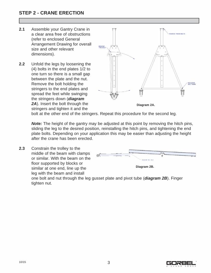
2.1 Assemble your Gantry Crane in a clear area free of obstructions (refer to enclosed General Arrangement Drawing for overall size and other relevant dimensions).
2.2 Unfold the legs by loosening the (4) bolts in the end plates 1/2 to one turn so there is a small gap between the plate and the nut. Remove the bolt holding the stringers to the end plates and spread the feet while swinging the stringers down (diagram 2A). Insert the bolt through the stringers and tighten it and the bolt at the other end of the stringers. Repeat this procedure for the second leg.
Note: The height of the gantry may be adjusted at this point by removing the hitch pins, sliding the leg to the desired position, reinstalling the hitch pins, and tightening the end plate bolts. Depending on your application this may be easier than adjusting the height after the crane has been erected.
2.3 Constrain the trolley to the middle of the beam with clamps or similar. With the beam on the floor supported by blocks or similar at one end, line up the leg with the beam and install one bolt and nut through the leg gusset plate and pivot tube (diagram 2B). Finger tighten nut.
310/15
Diagram 2A.
Diagram 2B.
STEP 2 - CRANE ERECTION (CONTINUED)
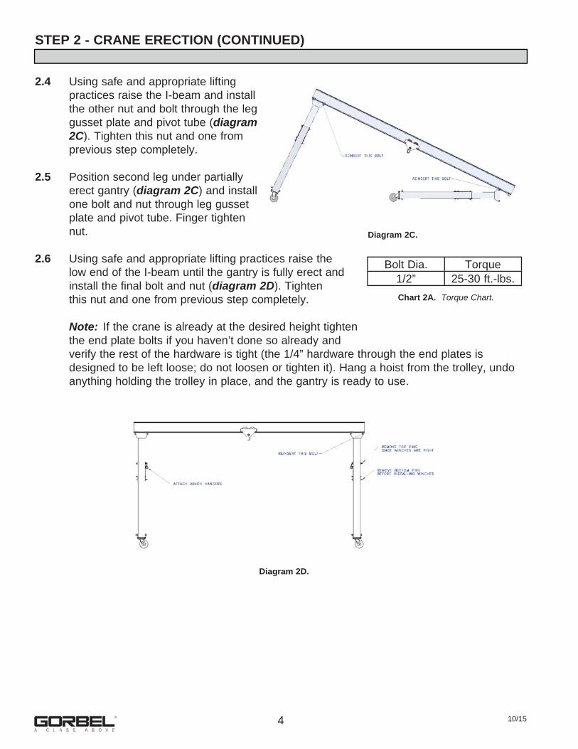
2.4 Using safe and appropriate lifting practices raise the I-beam and install the other nut and bolt through the leg gusset plate and pivot tube (diagram 2C). Tighten this nut and one from previous step completely.
2.5 Position second leg under partially erect gantry (diagram 2C) and install one bolt and nut through leg gusset plate and pivot tube. Finger tighten nut.
2.6 Using safe and appropriate lifting practices raise the low end of the I-beam until the gantry is fully erect and install the final bolt and nut (diagram 2D). Tighten this nut and one from previous step completely.
Note: If the crane is already at the desired height tighten the end plate bolts if you haven’t done so already and verify the rest of the hardware is tight (the 1/4” hardware through the end plates is designed to be left loose; do not loosen or tighten it). Hang a hoist from the trolley, undo anything holding the trolley in place, and the gantry is ready to use.
4 10/15
Chart 2A. Torque Chart.
Bolt Dia. Torque1/2” 25-30 ft.-lbs.
Diagram 2D.
Diagram 2C.
STEP 3 - HEIGHT ADJUSTMENT (WITH OPTIONAL WINCHES)
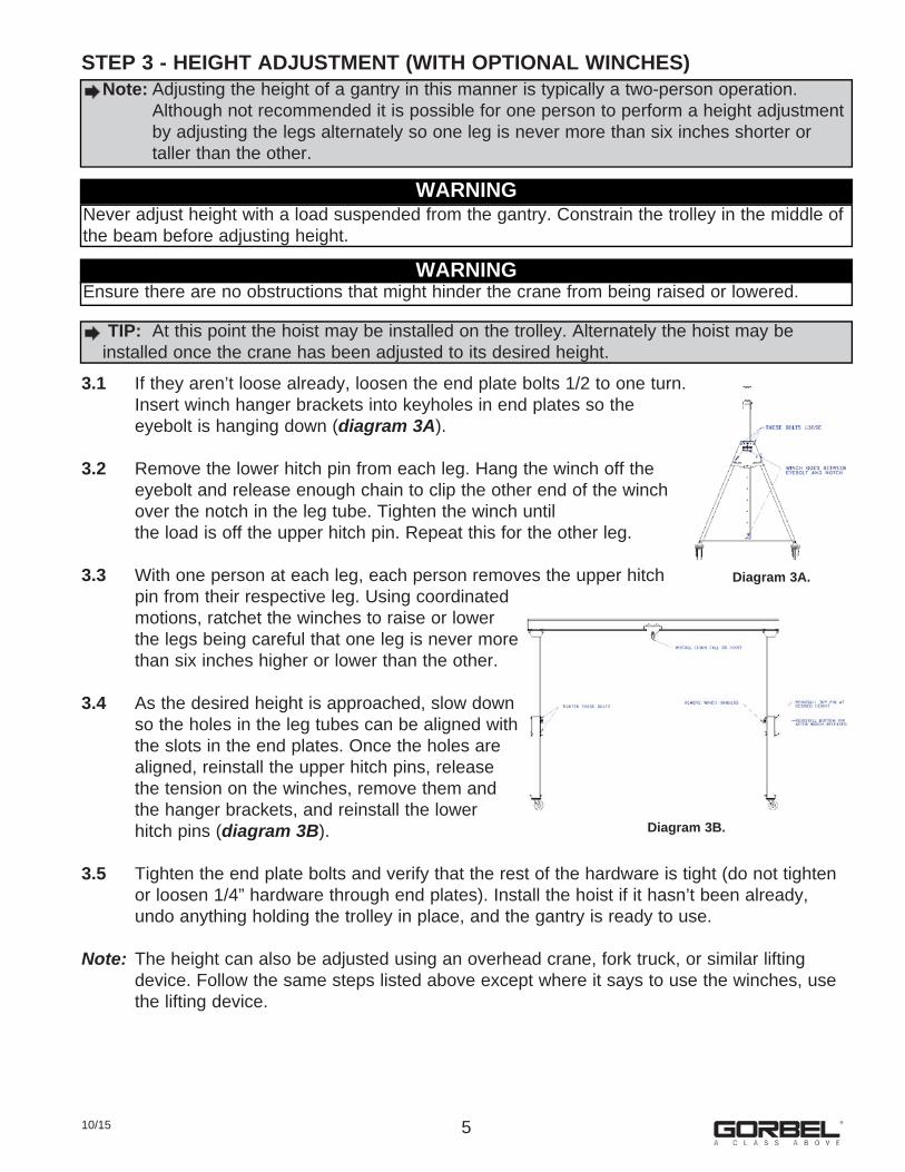
3.1 If they aren’t loose already, loosen the end plate bolts 1/2 to one turn. Insert winch hanger brackets into keyholes in end plates so the eyebolt is hanging down (diagram 3A).
3.2 Remove the lower hitch pin from each leg. Hang the winch off the eyebolt and release enough chain to clip the other end of the winch over the notch in the leg tube. Tighten the winch until the load is off the upper hitch pin. Repeat this for the other leg.
3.3 With one person at each leg, each person removes the upper hitch pin from their respective leg. Using coordinated motions, ratchet the winches to raise or lower the legs being careful that one leg is never more than six inches higher or lower than the other.
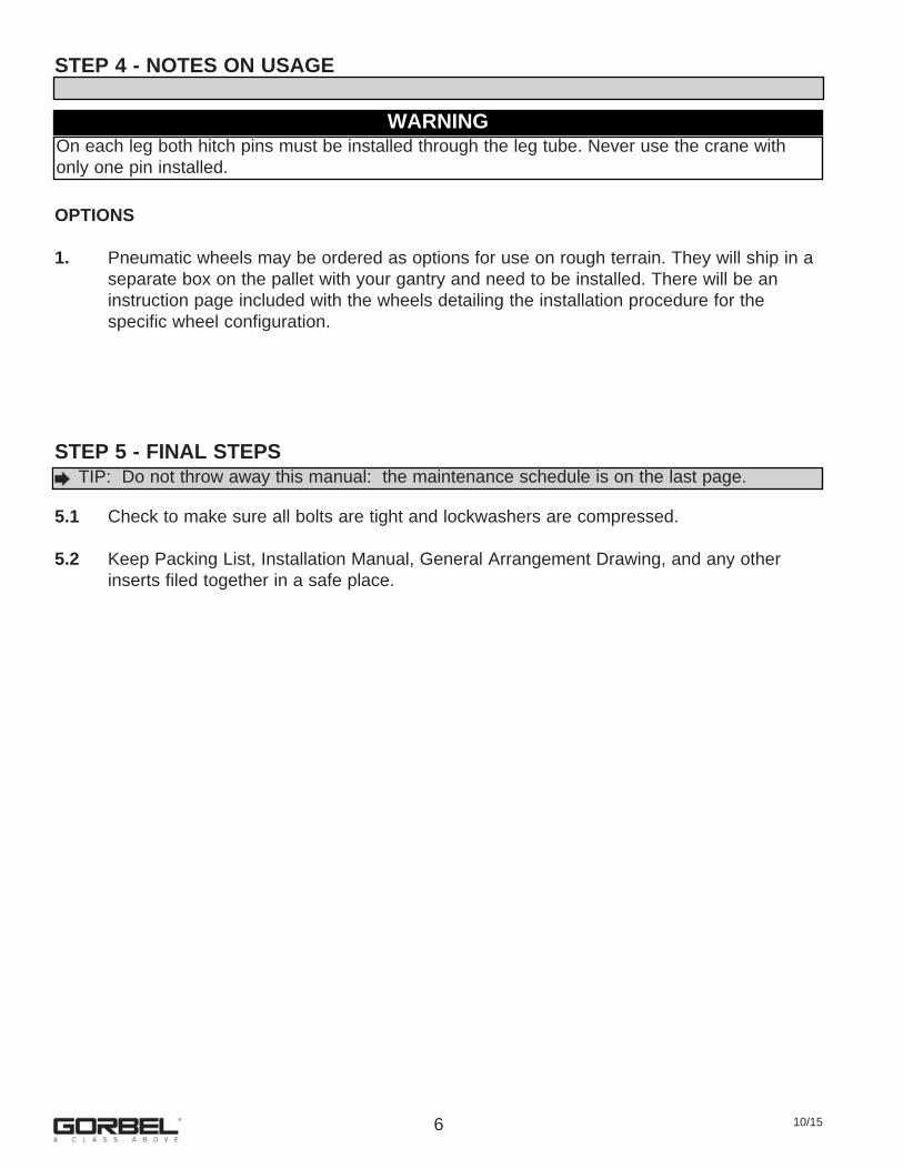
3.4 As the desired height is approached, slow down so the holes in the leg tubes can be aligned with the slots in the end plates. Once the holes are aligned, reinstall the upper hitch pins, release the tension on the winches, remove them and the hanger brackets, and reinstall the lower hitch pins (diagram 3B).
3.5 Tighten the end plate bolts and verify that the rest of the hardware is tight (do not tighten or loosen 1/4” hardware through end plates). Install the hoist if it hasn’t been already, undo anything holding the trolley in place, and the gantry is ready to use.
Note: The height can also be adjusted using an overhead crane, fork truck, or similar lifting device. Follow the same steps listed above except where it says to use the winches, use the lifting device.
510/15
Note: Adjusting the height of a gantry in this manner is typically a two-person operation. Although not recommended it is possible for one person to perform a height adjustment
by adjusting the legs alternately so one leg is never more than six inches shorter or taller than the other.
WARNINGNever adjust height with a load suspended from the gantry. Constrain the trolley in the middle of the beam before adjusting height.
WARNINGEnsure there are no obstructions that might hinder the crane from being raised or lowered.
TIP: At this point the hoist may be installed on the trolley. Alternately the hoist may be installed once the crane has been adjusted to its desired height.
Diagram 3A.
Diagram 3B.
STEP 4 - NOTES ON USAGE
OPTIONS
1. Pneumatic wheels may be ordered as options for use on rough terrain. They will ship in a separate box on the pallet with your gantry and need to be installed. There will be an instruction page included with the wheels detailing the installation procedure for the specific wheel configuration.
STEP 5 - FINAL STEPS
5.1 Check to make sure all bolts are tight and lockwashers are compressed.
5.2 Keep Packing List, Installation Manual, General Arrangement Drawing, and any other inserts filed together in a safe place.
6 10/15
TIP: Do not throw away this manual: the maintenance schedule is on the last page.
WARNINGOn each leg both hitch pins must be installed through the leg tube. Never use the crane with only one pin installed.
710/15
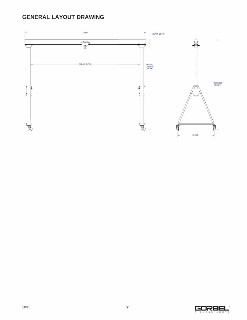
GENERAL LAYOUT DRAWING
CRANE OPERATOR INSTRUCTIONSOverhead cranes and jib cranes generally handle materials over working areas where there are personnel. Therefore, it is important for the Crane Operator to be instructed in the use of the crane and to understand the severe consequences of careless operation. It is not intended that these suggestions take precedence over existing plant safety rules and regulations or OSHA regulations. However, a thorough study of the following information should provide a better understanding of safe operation and afford a greater margin of safety for people and machinery on the plant floor. It must be recognized that these are suggestions for the Crane Operator’s use. It is the responsibility of the owner to make personnel aware of all federal, state and local rules and codes, and to make certain operators are properly trained.
QualificationsCrane operation, to be safe and efficient, requires skill: the exercise of extreme care and good judgment, alertness and concentration, and rigid adherence to proven safety rules and practices as outlined in applicable and current ANSI and OSHA safety standards. In general, no person should be permitted to operate a crane: • Who cannot speak the appropriate language or read and understand the printed instructions. • Who is not of legal age to operate this type of equipment. • Whose hearing or eyesight is impaired (unless suitably corrected with good depth perception). • Who may be suffering from heart or other ailments which might interfere with the operator’s safe performance. • Unless the operator has carefully read and studied this operation manual. • Unless the operator has been properly instructed. • Unless the operator has demonstrated his instructions through practical operation. • Unless the operator is familiar with hitching equipment and safe hitching equipment practices.
Handling the Trolley MotionBefore a load is handled, the hoist should be positioned directly over the load that is to be handled. When the slack is taken out of the slings, if the hoist is not directly over the load, bring it directly over the load before hoisting is continued. Failure to center the hoist over the load may cause the load to swing upon lifting. Always start the trolley motion slowly and reduce the trolley speed gradually.
Handling the Hoist MotionRefer to the lifting (hoist) equipment’s operating instructions.
GENERAL SUGGESTIONSKnow Your CraneCrane operators should be familiar with the principal parts of a crane and have a thorough knowledge of crane control functions and movements. The crane operator should be required to know the location and proper operation of the main conductor disconnecting means for all power to the attachments on the crane.
ResponsibilityEach crane operator should be held directly responsible for the safe operation of the crane. Whenever there is any doubt as to SAFETY, the crane operator should stop the crane and refuse to handle loads until: (1) safety has been assured or (2) the operator has been ordered to proceed by the supervisor, who then assumes all responsibility for the SAFETY of the lift.Do not permit ANYONE to ride on the hook or a load
InspectionTest the crane movement and any attachments on the crane at the beginning of each shift. Whenever the operator finds anything wrong or apparently wrong, the problem should be reported immediately to the proper supervisor and appropriate corrective action taken.
Operating SuggestionsOne measure of a good crane operator is the smoothness of the crane operation. The good crane operator should know and follow these proven suggestions for safe, efficient crane handling.1. The crane should be moved smoothly and gradually to avoid abrupt, jerky movements of the load. Slack must be removed from the sling and hoisting ropes before the load is lifted.2. Center the crane over the load before starting the hoist to avoid swinging the load as the lift is started. Loads should not be swung by the crane to reach areas not under the crane.3. Crane-hoisting ropes should be kept vertical. Cranes shall not be used for side pulls.4. Be sure everyone in the immediate area is clear of the load and aware that a load is being moved.5. Do not make lifts beyond the rated load capacity of the crane, sling chains, rope slings, etc.6. Make certain that before moving the load, load slings, load chains, or other lifting devices are fully seated in the saddle of the hook with hook latch closed (if equipped with hook latch).7. Check to be sure that the load and/or bottom block is lifted high enough to clear all obstructions when moving boom or trolley.8. At no time should a load be left suspended from the crane unless the operator has the push button with the power on, and under this condition keep the load as close as possible to the floor to minimize the possibility of an injury if the load should drop. When the crane is holding a load, the crane operator should remain at the push button.9. Do not lift loads with sling hooks hanging loose. If all sling hooks are not needed, they should be properly stored, or use a different sling.10. All slings or cables should be removed from the crane hooks when not in use (dangling cables or hooks hung in sling rings can inadvertently snag other objects when the crane is moving).11. Operators shall not carry loads and/or empty bottom blocks over personnel. Particular additional caution should be practiced when using magnet or vacuum devices. Loads, or parts of loads, held magnetically could drop. Failure of power to magnets or vacuum devices can result in dropping the load. Extra precaution should be exercised when handling molten metal in the proximity of personnel.12. Whenever the operator leaves the crane the following procedure should be followed: • Raise all hooks to an intermediate position. • Spot the crane at an approved designated location. • Place all controls in the “off” position. • Open the main switch to the “off” position. • Make visual check before leaving the crane.13. In case of emergency or during inspection, repairing, cleaning or lubrication, a warning sign or signal should be displayed and the main switch should be locked in the “off” position. This should be done whether the work is being done by the crane operator or by others.14. Contact with rotation stops or trolley end stops shall be made with extreme caution. The operator should do so with particular care for the safety of persons below the crane, and only after making certain that any persons on the other cranes are aware of what is being done.15. ANY SAFETY FEATURES AND MECHANISMS BUILT-IN OR OTHERWISE PROVIDED WITH THE CRANE BY GORBEL ARE REQUIRED FOR THE SAFE OPERATION OF THE CRANE. DO NOT, UNDER ANY CIRCUMSTANCES, REMOVE OR OTHERWISE IMPAIR OR DISABLE THE PROPER FUNCTIONING OF ANY CRANE SAFETY MECHANISMS OR FEATURES BUILT-IN OR OTHERWISE PROVIDED BY GORBEL FOR SAFE OPERATION OF THE CRANE. ANY REMOVAL, IMPAIRMENT OR DISABLING OF ANY SUCH SAFETY MECHANISMS OR FEATURES OR OTHER USE OR OPERATION OF THE CRANE WITHOUT THE COMPLETE AND PROPER FUNCTIONING OF ANY SUCH SAFETY MECHANISMS OR FEATURES AUTOMATICALLY AND IMMEDIATELY VOIDS ANY AND ALL EXPRESS AND IMPLIED WARRANTIES OF ANY KIND OR NATURE.
8 10/15
LIMITED WARRANTYIt is agreed that the equipment purchased hereunder is subject to the following LIMITED warranty and no other. Gorbel Incorporated (“Gorbel”) warrants the manual push-pull Work Station Cranes, Jib Crane, and Gantry Crane products to be free from defects in material or workmanship for a period of ten years or 20,000 hours use from date of shipment. Gorbel warrants the Motorized Work Station Cranes and Jib Crane products to be free from defects in material or workmanship for a period of two years or 4,000 hours use from the date of shipment. Gorbel warrants the G-Force® and Easy Arm™ products to be free from defects in material orworkmanship for a period of one year or 2,000 hours use from the date of shipment. This warranty does not cover Gantry Crane wheels.This warranty shall not cover failure or defective operation caused by operation in excess of recommended capacities, misuses, negligence or accident, and alteration or repair not authorized by Gorbel. No system shall be field modified after manufacture without the written authorization of Gorbel, Inc. Any field modification made to the system without thewritten authorization of Gorbel, Inc. shall void Gorbel’s warranty obligation. OTHER THAN AS SET FORTH HEREIN, NO OTHER EXPRESS WARRANTIES, AND NO IMPLIED WARRANTIES, ORAL OR WRITTEN, INCLUDING BUT NOT LIMITED TO THE WARRANTIES OF MERCHANTABILITY OR FITNESS FOR PARTICULAR PURPOSE, ARE MADE BY GORBEL WITH RESPECT TO ITS PRODUCTS AND ALL SUCH WARRANTIES ARE HEREBY SPECIFICALLY DISCLAIMED. GORBEL SHALL NOT BE LIABLE UNDER ANY CIRCUMSTANCES FOR ANY INCIDENTAL, SPECIAL AND/OR CONSEQUENTIAL DAMAGES WHATSOEVER, WHETHER OR NOT FORESEEABLE, INCLUDING BUT NOT LIMITED TO DAMAGES FOR LOST PROFITS AND ALL SUCH INCIDENTAL, SPECIAL AND/OR CONSEQUENTIAL DAMAGES ARE HEREBY ALSO SPECIFICALLY DISCLAIMED. Gorbel’s obligation and Purchaser’s or end user’s sole remedy under thiswarranty is limited to the replacement or repair of Gorbel’s products at the factory, or at the discretion of Gorbel, at a location designated by Gorbel. Purchaser or end user shall be solely responsible for all freight and transportation costs incurred in connection with any warranty work provided by Gorbel hereunder. Gorbel will not be liable for any loss, injury or damage to persons or property, nor for damages of any kind resulting from failure or defective operation of any materials or equipmentfurnished hereunder. Components and accessories not manufactured by Gorbel are not included in this warranty. Purchaser’s or end user’s remedy for components and accessories not manufactured by Gorbel is limited to and determined by the terms and conditions of the warranty provided by the respective manufacturers of such components and accessories. A) DISCLAIMER OF IMPLIED WARRANTY OF MERCHANTABILITY Gorbel and Purchaser agree that any claim made by Purchaser which is inconsistent with Gorbel’s obligations and the warranty remedies provided with Gorbel’s products, and in particular, special, incidental and consequential damages, are expressly excluded. B) DISCLAIMER OF IMPLIED WARRANTY OF FITNESS FOR PARTICULAR PURPOSE Gorbel and Purchaser agree that the implied warranty of fitness for particular purpose is excluded from this transaction and shall not apply to the goods involved in this transaction. C) DISCLAIMER OF EXPRESS WARRANTY Gorbel’s agents, or dealer’s agents, or distributor’s agents may have made oral statements about the machinery and equipment described in this transaction. Such statements do not constitute warranties, and Purchaser agrees not to rely on such statements. Purchaser also agrees that such statements are not part of this transaction. D) DISCLAIMER OF SPECIAL, INCIDENTAL AND CONSEQUENTIAL DAMAGES Gorbel and Purchaser agree that any claim made by Purchaser which is inconsistent with Gorbel’s obligations and the warranty remedies provided with Gorbel’s products, and in particular, special, incidental and consequential damages, are expressly excluded. E) DEALER OR DISTRIBUTOR NOT AN AGENT Gorbel and Purchaser agree that Purchaser has been put on notice that dealer or distributor is not Gorbel’s agent in any respect for any reason. Gorbel and Purchaser also agree that Purchaser has been put on notice that dealer or distributor is not authorized to incur any obligations or to make any representations or warranties on Gorbel’s behalf other than those specifically set forth in Gorbel’s warranty provided in connection with its product. F) MERGER This warranty agreement constitutes a final and complete written expression of all the terms and conditions of this warranty and is a complete and exclusive statement of those terms. G) PAINTING Every crane (excluding components) receives a quality paint job before leaving the factory. Unfortunately, no paint will protect against the abuses received during the transportation process via common carrier. We have included at least one (1) twelve ounce spray can for touchup with each crane ordered (unless special paint was specified). If additional paint is required, contact a Gorbel® Customer Service Representative at 1-800-821-0086 or 1-585-924-6262.
Title and Ownership: Title to the machinery and equipment described in the foregoing proposal shall remain with Gorbel and shall not pass to the Purchaser until the full amount herein agreed to be paid has been fully paid in cash.
Claims and Damages: Unless expressly stated in writing, goods and equipment shall be at Purchaser’s risk on and after Seller’s delivery in good shipping order to the Carrier. Gorbel shall in no event be held responsible for materials furnished or work performed by any person other than it or its authorized representative or agent.
Cancellations: If it becomes necessary for the purchaser to cancel this order wholly or in part, he shall at once so advise Gorbel in writing. Upon receipt of such written notice all work will stop immediately. If the order entails only stock items, a flat restocking charge of 15% of the purchase price will become due and payable by Purchaser to Gorbel. Items purchased specifically for the canceled order shall be charged for in accordance with the cancellation charges of our supplier plus 15% for handling in our factory. The cost of material and/or labor expended in general fabrication for the order shall be charged for on the basis of total costs to Gorbel up to the time of cancellation plus 15%.
Returns: No equipment, materials or parts may be returned to Gorbel without express permission in writing to do so.
Extra Charge Delay: If Purchaser delays or interrupts progress of Seller’s performance, or causes changes to be made, Purchaser agrees to reimburse Gorbel for expense, if any, incident to such delay.
Changes and Alterations: Gorbel reserves the right to make changes in the details of construction of the equipment, as in its judgment, will be in the interest of the Purchaser; will make any changes in or additions to the equipment which may be agreed upon in writing by the Purchaser; and Gorbel is not obligated to make such changes in products previously sold any customer.
Third Party Action: Should Gorbel have to resort to third party action to collect any amount due after thirty (30) days from date of invoice, the Purchaser agrees to pay collection costs, reasonable attorney’s fees, court costs and legal interest.
OSHA Responsibilities: Gorbel agrees to fully cooperate with Purchaser in the design, manufacture or procurement of safety features or devices that comply with OSHA regulations. In the event additional equipment or labor shall be furnished by Gorbel, it will be at prices and standard rates then in effect, or as may be mutually agreed upon at the time of the additional installation.
Equal Employment Opportunity: Gorbel agrees to take affirmative action to ensure equal employment opportunity for all job applicants and employees without regard to race, color, age, religion, sex, national origin, handicap, veteran, or marital status. Gorbel agrees to maintain non-segregated work facilities and comply with rules and regulations of the Secretary of Labor or as otherwise provided by law or Executive Order.
910/15

INSPECTION AND MAINTENANCE
*Federal, state and local codes may require inspection and maintenance checks more often. Please check the federal, state and local code manuals in your area.
600 Fishers Run, P.O. Box 593Fishers, NY 14453-0593Phone: (800) 821-0086
Fax: (800) 828-1808E-Mail: [email protected]
http://www.gorbel.com
© 2015 Gorbel Inc.All Rights Reserved
10 10/15
WARNINGAny changes in rolling effort or unusual noises must be immediately identified and corrected.
GORBEL® GANTRY CRANE INSPECTION AND MAINTENANCE SCHEDULEITEM COMPONENT MAINTENANCE FREQUENCY*
1 Pivot Block Hardware
Check for full compression of lockwasher. Bolts should be tightened to torque specifications (chart 2A, page 4).
Every time unit is erected or 6 months
2 Caster Hardware Bolts should be tightened to torque specifications (chart 2A, page 4).
Every 1,000 hours or 6 months
3 Leg Hardware Bolts should be tightened to torque specifications (chart 2A, page 4).
Every time unit is erected or 6 months
4 Casters
Check for cracks, pits, grooves or excessive wear: all of these hinder the crane’s mobility. If any of these conditions exist, wheels should be replaced. Also add an adequate amount of grease through the zirk fittings. Each caster will have one or two grease fittings (one on the fork weldment and one on the wheel itself).
Every 1,000 hours or 6 months
FacebookFacebook.com/gorbelinc
Twi ertwi er.com/gorbelinc
linkedin.com/company/gorbel youtube.com/gorbelmarke ng gorbel.com/blog