Embed Size (px)
Citation preview

Installation, Operation & Maintenance Manual
For the latest updated versions of this or other Seresco Installation, Operation & Maintenance Manuals contact
Seresco Technologies Inc. Tel: (613) 741-3603Visit: www.serescodehumidifiers.com
Issue Date : 2011-09-30
NV Series Dehumidifiers

Issue Date : 2011-09-30
THIS PAGE HAS BEEN INTENTIONALLY LEFT BLANK
2

Issue Date : 2011-09-30 Table of Contents (NV Series).doc
Section Section Title Page(s)
A Warnings, Cautions and Notices
Warnings, Cautions and Notices A-1
B NE/NP/NV Series General Information
General Information B-1
Unit Description B-1
Component Descriptions B-2
Product Nomenclature B-3
Unit Label B-6
Further Information B-7
C Pre-installation Requirements
Pre-installation Requirements C-1
Receiving Checklist C-1
Shipping Damage Instructions C-1
Storage C-2
D Mechanical Installation
Mechanical Installation D-1
Lifting and Rigging Procedures D-1
Unit Assembly D-1
Duct Connections D-1
Piping and Unit Connections D-2
Drain Pans – Condensate Drain D-2
Blower Motor Brace D-3
Factory Start-up Supervision D-4
E Electrical Installation
Electrical Installation E-1
Main Panel Power Connection E-1
Control Wiring E-2
Websentry Connection E-3
Remote Operator Panel E-4

Table of Contents (NV Series).doc Issue Date : 2011-09-30
F Start-up
Start-up F-1
Pre-Startup Checklist F-1
Start-up Procedure F-3
Factory Start-up Supervision F-6
G NE/NP/NV Series Operation
Sequence of Operation G-1
CommandCenter Operation G-5
H Routine Maintenance
Routine Maintenance H-1
Routine Maintenance Checklist H-1
Component Maintenance H-2
Outdoor Air Balancing H-5
X Troubleshooting
Troubleshooting X-1
Troubleshooting Steps X-1
Contacting Service and Technical Support X-1
Websentry Troubleshooting X-2
Y Warranty
Warranty Y-1
Z Annex

Issue Date : 2011-10-06 Section A - Warnings, Cautions and Notices (NV Series)
Warnings, Cautions and Notices
Throughout this manual, warnings, cautions and notes appear when special care must be taken to avoid potential hazards
that could result in mechanical or electrical damage, personal injury or death.
WARNING Indicates a potentially hazardous situation which could result in serious injury or
death if handled improperly.
CAUTION Indicates a potentially hazardous situation which could result in moderate injury or
equipment damage if handled improperly.
Note : Indicates a situation that could result in equipment damage if handled improperly.
A-1

Section A - Warnings, Cautions and Notices (NV Series) Issue Date : 2011-10-06
THIS PAGE HAS BEEN INTENTIONALLY LEFT BLANK
A-2

Issue Date : 2011-10-06 Section B - NV Series General Information
General Information
Use this manual to install, operate and maintain your Seresco Technologies Inc. (Seresco) NV Series dehumidification unit.
Carefully review the procedures and instructions in this manual to minimize installation and operation difficulties. Every
Seresco dehumidification unit is accompanied by a label that identifies the unit serial number, mechanical, refrigeration and
electrical operating information. This information is required when ordering parts or requesting service for a Seresco
dehumidification system. Seresco also publishes a comprehensive natatorium design guide which provides a wealth of
information on how to design a pool. See www.serescodehumidifiers.com for more information.
Unit Description
Seresco's NV Series advanced dehumidifiers are designed for residential or commercial indoor pools and other various
dehumidification requirements.
Figure B-1. Heat recovery circuit
B-1

Section B - NV Series General Information Issue Date : 2011-10-06
Component Descriptions
The following components are commonly used on Seresco Technologies Inc.'s NV Series of dehumidifiers. Detailed
technical information can be found in the annex and in the respective manufacturer's IOM manual(s).
Variable Frequency Drives
Used on main fans for air balancing and on exhaust 2 to modulate airflow by changing the frequency of the input power.
Exhaust 2 airflow is modulated according to a 0 – 10V signal from the unit's microprocessor.
Electronically Commutated Motorized Impellers
Used on exhaust 1, the speed of these motors can be modulated by a 0 – 10V signal.
Indirect Gas-Fired Heaters
Used for space heating when the return air temperature is below the set-point. The level of heat is fully adjustable through
the use of a single modulating heater and multiple single-stage heaters (if required).
Actuators
On / Off actuators are used to control dampers on the exhaust outlets, while proportional actuators are used to control
internal dampers that regulate airflow according to a signal from the unit's microprocessor.
B-2

Issue Date : 2011-10-06 Section B - NV Series General Information
Product Nomenclature
The product nomenclature is a 27 character alpha-numeric sequence that completely describes the options present on the
dehumidification unit.
Table B-1. Seresco Technologies Inc. Nomenclature Definition Version 3.2
Series
Natatorium Environmental Control Series NE
Natatorium Protocol Series NP
Natatorium Ventilation Series NV
Dash Dash -
Tonnage
2 ton 002
...16 ton 016
18 ton 018
...80 ton 080
10 ton “double decker” 210
...32 ton “double decker” 232
Dash Dash -
Pool HeaterNo Pool Water Heater N
Pool Water Heater P
Cabinet
Configurations
Double walled - Return plenum - Bottom B
Double walled - Horizontal Return C
Horizontal -single wall Standard H
Horizontal - single wall - Mirrored M
Vertical - single wall Mirrored N
Double walled - Return plenum - Right Side R
Double walled - Return plenum - Left Side S
Double walled - Return plenum - Top T
Vertical - single wall Standard V
Special Z
Dash Dash -
Indoor/OutdoorIndoor Unit I
Exterior Unit X
Dash Dash -
AC Options
Outdoor Air Cooled Condenser A
Glycol Cooled By a Fluid Cooler G
Air Handler (Chilled Water Coil) H
Water Cooled - Variable Flow (< 65F Water Loop) M
No Air Conditioning (All AC components removed) N
Packaged/Integral Air Cooled Condenser P
Water Cooled - Variable Flow (70-85F Water Loop) V
Outdoor
Air Options
None 0
Duct Connection Collar Only 1
B-3

Section B - NV Series General Information Issue Date : 2011-10-06
Duct Collar c/w Manual Damper & Filter 2
OA Inlet Motorized Damper & Filter 3
Purge/Economizer Motorized Damper (In addition to OA Motorized Damper Option) 4
Heat Recovery Package with Motorized Damper and Time Clock 5
Heat Recovery Package Option on OA with Additional Purge/Economizer Option 6
Exhaust Fan
Unit mounted Exhaust fan (Required with HR) E
Unit mounted Exhaust fan and Purge/Economizer Fan F
None N
Unit mounted Purge/Economizer Fan P
Supply Air
Orientation
Bottom Supply B
Top Right Supply D
Horizontal - Loopback E
Top Loopback End Supply F
Top Left Supply G
Horizontal (Straight Through) H
Top Horizontal End Supply J
Left (oriented with airflow air turns left out of unit) L
Right (oriented with airflow air turns right out of unit) R
Top Supply T
External
Static Pressure
0.5" 0
0.75" 4
1.0" 1
1.5" 5
2.0" 2
Other 3
Supply Air CFM
X
XY times 10 to the N Y
N
Space Heating
Type
Unit mounted electric Heater - Separate power connection D
Unit mounted electric heater - Single point power connection E
Unit mounted gas heating G
Remote by others N
Unit mounted steam coil S
Remote electric heater supplied by Seresco T
Unit mounted hot water coil W
Remote electric modulating heater supplied by Seresco X
Remote hot water coil supplied by Seresco Y
Remote steam coil supplied by Seresco Z
Heating Control
Details
Standard control signals: Valve and power supply by others 0
2 stages factory wired electric heating control 1
Modulating - factory supplied and wired valve 2
B-4

Issue Date : 2011-10-06 Section B - NV Series General Information
On/Off - factory supplied and wired Valve 3
Supply isolated 50 VA power for remote valve ( valve by others) 4
Modulating factory wired electric heating control 5
Supply On/Off Valve & 50 VA power for remote valve installation 6
Supply Modulating Valve & 50 VA power for remote valve installation 7
Unit Supply
Voltage
208/1 A
230-240/1 B
208/3 C
230-240/3 D
460-480/3 E
575-600/3 G
Unit Controls
Electro-mechanical 0
Command Touch Screen 1
Command Center 2
Command Center c/w Building Communication 3
Command Center c/w Remote Panel 4
Command Center c/w Building Communications & Remote Panel 5
Refrigerant
R410A A
R407C C
R22 R
Disconnect
Non fused Disconnect D
Fused Disconnect F
No Disconnect N
Warranties Standard - 2yrs on driveline, coils, and compressor 0
2 yrs on driveline and compresor, 5 yrs on coils 1
2 yrs on driveline and compressor, 10 yrs on electrofined coils 2
2 yrs on driveline and coils, 5 years on compressor 3
2 yrs on driveline, 5 yrs on compressor and coils 4
2yrs on driveline, 5 yrs on compressor, 10 yrs on electrofined coils 5
2yrs on driveline and coils, 10 yrs on compressor 6
2yrs on driveline, 10 yrs on compressor, 5 years on coils 7
2yrs on driveline 10 yrs on compressor and electrofined coils 8
5yrs on driveline, 2 yrs on compressor and coils 9
5yrs on driveline and coils, 2 yrs on compressor A
5yrs on driveline, 2 yrs on compressor, 10 years on electrofined coils B
5yrs on driveline and compressor, 2 yrs on coils C
5yrs on driveline, compressor and coils D
5 yrs on driveline and compressor, 10 yrs on electrofined coils E
5 yrs on driveline, 10 years on compressor, 2 yrs on coils F
5 yrs on driveline and coils, 10 yrs on compressor G
5 yrs on driveline, 10 years on compressor and electrofined coils H
B-5

Section B - NV Series General Information Issue Date : 2011-10-06
Unit Label
B-6

Issue Date : 2011-10-06 Section B - NV Series General Information
Further Information
For further information, please visit our website at www.serescodehumidifiers.com. Feel free to browse our website and
watch informative videos on every aspect of our products.
B-7

Section B - NV Series General Information Issue Date : 2011-10-06
THIS PAGE HAS BEEN INTENTIONALLY LEFT BLANK
B-8

Issue Date : 2011-09-30 Section C - Pre-installation Requirements
Pre-installation Requirements
Seresco Technologies Inc. inspects and fully tests each dehumidifier in all operating modes before it ships from the factory.
The unit can suffer damage in transit. Check the equipment thoroughly for both visible and concealed damage before you
sign the receiving papers. Document any damage in writing on the carrier’s bill of lading to ensure that damage claims are
handled promptly. If the unit has been damaged, obtain a claim form from the carrier. Promptly fill out and return the form,
and notify Seresco Technologies Inc. of any damage.
Note : Damage claims or missing parts must be filed with the freight carrier.
Receiving Checklist
Note : The shipping protection provided by the factory is for transport purposes only and should not be
relied on to protect the unit in storage or on the job site.
Note : Seresco is not responsible for any shipping damages. Should your unit arrive damaged, please
follow the instructions in Shipping Damage Instructions to resolve the situation. Delivery cannot be refused
on the basis of shipping damages.
Upon receipt, please check the following components for damage:
Verify the proper operation of latches and hinges on all access doors
Inspect all coils for damage to the fin surface coating, headers or coil connections
Manually rotate the fan wheel to ensure free movement of the shaft, bearings and drive
Inspect the fan housings for any foreign objects
Inspect and test all piping for possible shipping damage
Check the tightness of bolts on the fan structure and coils
Inspect fan isolator shipping brackets
Shipping Damage Instructions
Seresco Technologies Inc. ships freight on board (FOB), meaning that the unit belongs to the customer as soon as the
delivery truck leaves the factory. If damage has occurred to the unit during shipment, follow these instructions:
1. Specifically note the extent of the damage in detail on the freight bill. Clear photographs of the damaged
C-1
Section C - Pre-installation Requirements Issue Date : 2011-09-30
components are required.
2. Report all claims of shipping damage to the delivering carrier immediately and coordinate a carrier
inspection if necessary.
3. Contact Seresco Technologies Inc. by email at [email protected] or by phone at (613)-741-
3603 and dial 2 for the soonest available tech support technician. Have the unit serial number (8-digit) and
nomenclature designation (23 digit alpha-numeric sequence starting with the series designation) on hand.
These may be found on the unit label along with other performance and electrical information.
4. Do not attempt to repair the unit without consulting the Seresco Technologies Inc. Service and Tech
Support Department. It is the receiver's responsibility to provide reasonable evidence that damage was not
incurred after delivery.
Storage
Protection from the elements is required for any unit that will be stored on the job site or a holding area before installation.
For long term storage, a controlled indoor environment is highly recommended. All factory-applied shipping protection
should be removed before the unit is put into storage. Shipping protection material is not suitable protection for short or
long-term storage.
Note : Standard Seresco warranties expire 24 months from the date of shipment.
See section Y – Warranties for further information.
C-2

Issue Date : 2011-10-06 Section D - Mechanical Installation (NV Series)
Mechanical Installation
WARNING Heavy objects ! Do not use cables (chains or slings) except as shown. Each of the
cables (chains or slings) used to lift the unit must be capable of supporting the entire weight of the unit.
Lifting cables (chains or slings) may not be of the same length. Adjust as necessary for an even unit lift.
Other lifting arrangements may cause damage to equipment, serious injury or death of personnel. Always
place, assemble, and suspend single sections. Do not lift units in windy conditions. Do not raise units
overhead with personnel below unit.
WARNING Improper lifting procedure ! Test lift the unit 24 inches to verify proper operation of
lifting equipment and positioning of lift points such that the unit is level. Failure to properly lift the unit
could result in equipment damage, serious injury or death. Seresco Technologies Inc. is not responsible for
the improper use of lifting equipment.
WARNING When lifting unit, appropriate personal protection equipment (PPE) such as steel-
toed boots and hard hats must be worn to avoid potentially serious injury.
Lifting and Rigging Procedures
Determine the approximate centre of gravity before lifting the unit. Consult unit design drawings provided in
the submittal documents to determine total weight and weight distribution.
Never assemble split sections before lifting them to the installation location. Always lift sections as received
from the factory.
Lift sections using the provided lifting lugs
To avoid damage, do not attach intake or exhaust hoods prior to lifting the unit into place.
Unit Assembly (Split Units Only)
Under special conditions, the unit may be split into two or more sections to ease the installation process. Base angles are
attached using 3/8” bolts, and inside angles are bolted using 5/16” bolts. Ensure that all provided holes are used. Caulk
seams on the outside of the unit to make the join air-tight. Install the standing seam roof rib.
D-1

Section D - Mechanical Installation (NV Series) Issue Date : 2011-10-06
Duct Connections
All duct connections should be installed in accordance with local and national standards. To ensure the highest fan
efficiency, duct turns and transitions should be made to minimize air friction losses and turbulence. See supplied unit
drawing from the submittal for location and size of unit duct connections. Use only flexible duct connectors to connect to
the unit.
Piping and Unit Connections
See the unit label for unit connection line sizes. The installer must endeavour to ensure that all industry standards for
refrigeration component installation are met. This includes but is not limited to; proper line sizing, materials, nitrogen
purging, brazing with Silfos 5 or better (NO SOFT SOLDER), evacuation, cleanliness, traps, long radius elbows and system
charging.
Drain Pans - Condensate Drain
The dehumidifier is a draw through configuration as a result the entire cabinet is under negative pressure. Without a P-trap,
condensate will not drain and the unit will overflow into your mechanical room.
Per Figure 5 pitch the condensate drain line a minimum of 1/8” per linear foot, and support the pipe with code-
approved hangers at least every 5 feet.
If the drain line passes through an unconditioned space, heat tracing is required to prevent the condensate in the
drain from freezing.
When gravity disposal is not possible, a condensate pump can be used. Follow the pump manufacturer’s installation
instructions.
Figure D-1. P Trap
D-2
Issue Date : 2011-10-06 Section D - Mechanical Installation (NV Series)
Blower Motor Brace
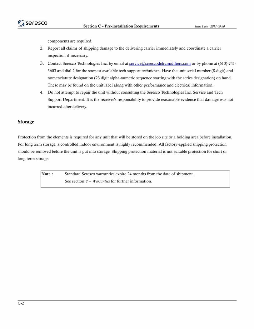
Upon installation remove ONLY lower bolt from all four corners shown in Figure D-2 (Detail A). The top of the bolt will
be spray-painted yellow for easy identification. The plug fan sits on spring dampers to minimize vibration translated to the
unit from the fan motor. During shipping, the fan assembly is fixed such that the springs are compressed and cannot
oscillate. Removing these bolts on installation ensures that the the fan vibrations will be dampened correctly.
Figure D-2. Blower Motor Brace
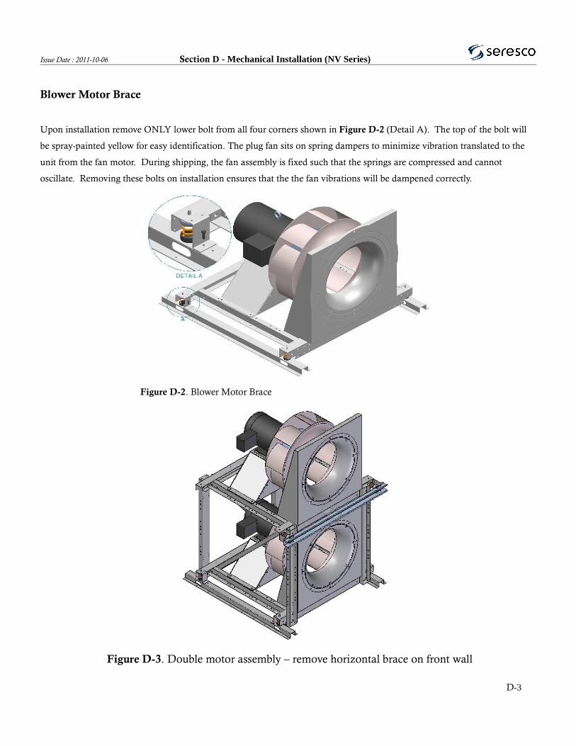
Figure D-3. Double motor assembly – remove horizontal brace on front wall
D-3

Section D - Mechanical Installation (NV Series) Issue Date : 2011-10-06
Factory Start-up Supervision
Seresco Technologies Inc. factory start-up supervision can be purchased with the equipment. A factory start-up
includes several key services:
The expertise of a factory-trained technician who will supervise the commissioning of the equipment.
This Seresco representative will assist the installing contractor with filling out the Start-Up Report.
They will also inspect the installation to make sure that the dehumidifier has been properly integrated with
the rest of the equipment on the job site.
Finally, they can train the maintenance personnel to operate and service the equipment if necessary.
A factory start-up does not include installation assistance. The installing contractor is responsible for ensuring
that the system is ready for start-up when the Seresco representative arrives. If the system is not ready, Seresco
reserves the right to bill the contractor for a second visit. When the installing contractor is confident the system
will be ready, contact the Seresco Sales representative to schedule the start-up. Please call at least two weeks
before the desired start-up date to prevent scheduling conflicts.
Items required for Start-Up
A service technician and a fully stocked service vehicle.
Air balancing equipment (magnehelic differential pressure gauge).
Volt/Amp/Ohm meters.
A digital thermometer w/clamp on sensors.
Items to be Completed Before Start-up
Leak-check and inspect the unit for internal concealed damage.
Level and support the dehumidifier properly.
Install the outdoor air duct filters and damper (if applicable).
Install the condensate P- trap and drain lines and prime P-trap.
Pipe the remote condenser fan pressure controls to the condenser hot gas lines (if applicable).
Evacuate and leak-check the remote condenser line set (if applicable).
Tighten all electrical connections and verify that the line voltage is correct for the unit.
Install all controls and verify that all field wiring matches the schematic.
Fill and heat the pool and room to design conditions.
Install the pool water piping and a flow meter (if applicable). Purge all air from pool lines.
A complete system air balancing.
D-4

Issue Date : 2011-09-30 Section E - Electrical Installation
Electrical Installation
WARNING Disconnect all electric power, including remote disconnects, before servicing. Follow
proper lockout procedures to ensure that the unit is not accidentally powered. For variable frequency
drives, refer to the appropriate section of the manual. Verify with a voltmeter that all capacitors have
discharged. Failure to disconnect power and discharge capacitors before servicing could result in serious
injury or death.
Note : Use copper conductors only ! Unit terminals are not designed to accept other types of conductors.
Use of aluminium or other wiring may result in galvanic corrosion or overheating.
Note : Properly seal all penetrations made in the outer walls. Failure to due so may result in
unconditioned air entering the unit, water infiltrating the insulation or serious equipment damage. Ensure
that all metal shards and filings are swept to avoid possible corrosion or damage to electrical components.
Main Panel Power Connection
The field-installed power supply wires and over current devices must be sized to handle the minimum ampacity of the
dehumidifier without exceeding the maximum fuse size rating. Both the MCA and MOP are indicated on the unit
nameplate. Figure E-1 shows typical power wiring connections. Single-phase units require 3 wires, 2 power and one ground.
Three-phase units require 3 power wires and one ground wire. Connect the power supply wires to the main power
distribution block located inside the unit main electrical panel. For units with electric heaters and single-point power
connections, the power distribution block is located in the heater. For units with electric heaters and dual-point power
connections, the unit and heater must be powered independently. For units with mounted disconnects, ensure that the power
is brought first to the disconnect and then the power distribution block. Always verify the nameplate voltage before
connecting to the unit.
E-1

Section E - Electrical Installation Issue Date : 2011-09-30
Figure E-1. Main power distribution block
Control Wiring
Seresco Technologies Inc.'s dehumidifiers have all necessary sensors unit mounted and setpoints pre-programmed at the
factory. Remote duct heaters, outdoor air-cooled condensers, auxiliary pool water heaters and remote exhaust fans all require
interfacing with the dehumidifier. The common connection terminals are identified in Table E-1. For a complete list of
terminal connections and functions, refer to section Z – Annex.
Table E-1. Control Terminals
Pin I/O's Description
Connector J7
6 DI14 Freezestat
7 DI15 Firestat
Connector J8
7 AO01 Modulated Heat
Connector J9
1 , 2 DO24 Space Heater, Stage 2
3 , 4 DO23 Space Heater, Stage 1
5 , 6 DO22 Exhaust Fan 2
7 , 8 DO21 Exhaust Fan 1
9 , 10 DO20 Outdoor Air Damper
Connector J10
1 , 2 DI19 Outdoor Air Condenser 1
3 , 4 DI18 Outdoor Air Condenser 2 (Ver. 5.x only)
5 , 6 DI17 Auxiliary Pool Heater, Pool 2
7 , 8 DI16 Auxiliary Pool Heater, Pool 1
E-2
Issue Date : 2011-09-30 Section E - Electrical Installation
WebSentry Connection
Requires RJ45 ethernet connection to the unit.
To get access to WebSentry® you need to register a user id with Seresco. Follow these instructions.
1) Go to the Seresco web page at http://www.serescodehumidifiers.com.
2) Select the Login link in the upper right corner.
3) Select the ‘Click here to register’ link in the WebSentry® login box.
4) Fill in the registration form and submit it. The email address will be your user id.
Follow these instructions to login to WebSentry® and view your Seresco unit.
1) Go to the Seresco web page at http://www. serescodehumidifiers.com.
2) Select the Login link in the upper right corner.
3) Enter login credentials in the WebSentry® login box and click Submit button.
4) Once you have logged in you will see a list of all Seresco units you have access to. The very first time you login
the list is empty since you do not yet have permission to see any unit (see Gain Access to Unit).
5) Too see more detailed information for a unit, click the job name link.
6) The main Conditions page shows you the current conditions including a trend graph showing the room
temperature, humidity and optionally the pool water temperature over the past 4 hours.
You can also see current setpoints, logs and some basic unit configuration by selecting the appropriate menu link.
Gain Access to Unit
To gain access to a Seresco unit you need to know the serial number of the unit and the last 6 characters of the MAC
address. The latter is printed on a bar code label on the control board where the network cable is plugged in. You can also
find this information from the System Info page from the key pad (accessible from User Settings). If you are not able to get
to this information you can also contact Seresco and someone will be able to help you get access to the unit.
Controlling Unit
To gain control of unit so that you can change setpoint, restart unit or modify some factory settings, you first have to
Connect to unit and have it maintain a live connection. By default the unit connects once a minute to upload latest sensors
readings and log entries and then disconnects again. Typically this does not take more than one second.
To get a live connection, click the Connect button on any page that has a Connect button. Keep pressing Connect button or
Web browser refresh button until Connect button changes to a Save and Refresh button.
E-3

Section E - Electrical Installation Issue Date : 2011-09-30
Another indication that unit is live is that the time stamp in the header under the job name changes to Live. Normally the
time stamp tells you the last time the unit connected to the WebSentry® server.
Once a live connection has been established you can change any unit parameter like setpoints and factory settings. From the
conditions page you can also start and stop the main blower and restart the unit. If unit is equipped with a purge feature, you
can also initiate purge from the conditions page.
Remote Operator Panel (ROP)
The Remote Operator Panel (ROP) looks identical to the local keypad but instead of being connected to the main control
board using a data ribbon cable, it uses a RS-485 serial port communication interface. Cat3 or Cat5 twisted pair cables must
be used between the ROP and the main CommandCenter control board.
The other difference between the local keypad and the ROP is that the ROP has its own processor and memory where the
menu system is stored opposed to the local keypad which just a “dumb” terminal displaying the menu system as controlled
by the main control board.
When installing or replacing the ROP you can run into several issues that will prevent the ROP from working properly. This
document covers all steps you need to take to ensure a good communication between ROP and main control board.
Testing Remote Operator Panel at the unit
To rule out any type of problem with the wiring between the unit and the ROP location, use a 3’-5’ wire and connect the
ROP to the main board right at the unit. All troubleshooting guides in this document applies to both testing ROP at the unit
and at its final location.
NOTE! When doing any rewiring like moving wires from J8 to JCOM or moving ROP between final location and testing it
at the unit, make sure the dip switches are in the off position (towards the 1 & 2 label on the dip switch socket). Do not move
to on position until powered up and red LED (L1) is lit up.
Using proper cable
We recommend using a twisted pair Cat3 or Cat5 cable. What is important is that the two signal wires are twisted together.
Twisting the signal wires together acts as a noise filter. If not using this type of cable you can run into communication issues.
E-4

Issue Date : 2011-09-30 Section E - Electrical Installation
Especially if the ROP is far away from the unit. For easier troubleshooting, use the following coloured wires.
Table E-2. ROP Connections
Cat3/Cat5 Wire Remote Keypad J8 JCOM
Orange J8-1 (+24V) Pin 1 Pin 5
White/Orange J8-2 (GND) Pin 2 Pin 4
Blue J8-5 (+ 485) Pin 5 Pin 6
White/Blue J8-6 (- 485) Pin 6 Pin 7
Connecting wires
Before doing any wiring, ensure there is no power over the wires. Either power unit off or unplug terminal (J8 or JCOM) to
where the ROP is connected. Connect wires to main control board terminal as listed in Table 1. By default you should be
using terminal J8. JCOM is only used as a backup RS-485 port or when more than one RS-485 port is needed. Open up the
back of the ROP and feed wires through the hole of the back plate and connect wires to terminals as listed in Table E-2.
Check communication
Power up unit or plug in terminal block again. If the two power wires are wired correctly you should now see the red L1
LED light lit up in the ROP. If there is power you can now safely activate the signal wires. You do this by moving the two
dip switches (SW1) next to the green terminal block towards the top of the ROP. This is easiest done by using a small flat
head screw driver.
If signal wires are wired up correctly you should see the main sensor screen within a few seconds (possibly the system
startup screen).
If the screen is blank, you see the Welcome screen for more than 10 seconds, or see other messages indicating the ROP is
trying to establish communication, continue reading this document to help you troubleshoot the problem.
No power to ROP (LED L1 not lit up)
First make sure unit is powered up and that the terminal block (J8 or JCOM) is plugged into the main control board.
Make sure wires are wired as listed in Table 1. Make sure that the terminal in the ROP is grabbing onto the copper and not
the insulation. Check this at the main control board as well. There could possible be a kink in the cable causing a broken
wire. Test ROP at unit using a short cable. Try both J8 and JCOM in case there still is no power connecting to J8. If still no
power you most likely have a failed ROP terminal board.
E-5

Section E - Electrical Installation Issue Date : 2011-09-30
Power to ROP but showing a blank screen
There should never be a blank screen when there is power to the ROP. At the minimum the ROP should show that it is trying
to connect to the main control board. There are only two reasons why there is a blank screen. The ROP has a contrast dial. It
might have been moved so that there is no contrast at all resulting in a blank screen. The contrast dial is a white dial in the
upper left corner next to the terminal board. Use a small screw driver to adjust it. If you see no change at all on the screen
when adjusting the dial, then this is not the problem. The second reason for a blank screen is if the menu program has been
erased from memory. A static chock could possible cause this. All ROP’s are tested at the factory so there should have been a
program installed when the ROP was shipped from factory. Once again, to really rule out a wiring issue, test the ROP using
a short cable right at the unit.
Power to ROP but not establishing a connection
First thing to check is that the two dip switches has been moved up to activate the signal wires. Make sure wires are wired as
listed in Table E-1. Make sure that the terminal in the ROP is grabbing onto the copper and not the insulation. Check this at
the main control board as well. There could possible be a kink in the cable causing a broken wire. Test ROP at unit using a
short cable. Try both J8 and JCOM in case there still is no communication when wired to J8. If still no communication, read
the next section to do one more last test.
Check for communication attempt
From the main control board you are able to look at data streams for anyone of the 3 serial ports. We can use this to
determine if the ROP at least is getting some message through to the main control board. Start up the unit in Service Mode.
Go to the Main Menu (1) and then Service (6) – Network (3) – Console (2). Use arrow keys to select port. Port D is RS-485
on J8 and Port C is RS-485 on JCOM. Select 1 to start serial port monitor console. If there is communication you should see
a bunch of characters within a few seconds. You should also see them changing every few seconds. Stop by pressing 2 or the
Back key. If there is no character stream them most likely the RS-485 communication chip on either the ROP or the main
controller board has failed. There is no way to check which one so if you do not have a second ROP a second board to test
with, there is no way to know. With our newer boards (4.1 and later) we have two RS-485 ports as discussed in this
document so the chances that both communication chips have failed are very small. For these boards we will replace the
ROP with a new one. For older units using a 3.1 board or older, there was only one RS-485 port so for these units we have to
replace both the main controller board and the ROP.
If there is a character stream but still no communication at the ROP, check the serial port communication settings to make
sure they have not been changed. See next section. Check serial port configuration settings. From the Main Menu, go to
E-6

Issue Date : 2011-09-30 Section E - Electrical Installation
Factory Settings (5) – Network (5) – Serial Ports (2). Then select either Port C (JCOM) or Port D (J8) depending on which
terminal you are testing. User should be set to Seresco, Baud Rate to 57600, Databits to 8, Parity to None. The timer Reply
Delay should be at least 500 but new recommendation is 750. The timer Invalid Data should be set to 1000.
Echo Test is by default set to Yes but you can try setting this to No to see if this will establish a connection. By default a RS-
485 is echoing back every sent message back to the sender. Our controller is using this to test for a robust connection. We
have however seen cases where the RS-485 communication chip partially has failed where it no longer echoes back sent
messages but otherwise functions just fine. By setting the Echo Test to No we can test for this fault.
If you did any configuration change but still no communication you can try doing a System Restart to see if it this will help.
Either power off unit in between or unplug ROP terminal from board to cycle the ROP. If you still are not being able to
establish communication after doing these steps, we have an unknown fault and the ROP needs to be replaced. If this already
is a new ROP, we need to replace the board.
ROP shows Version Mismatch
If the ROP display show Version Mismatch it means you are connecting a ROP to a unit running a software version with
which the ROP is not compatible. Get a new ROP with a version compatible with the software version on the unit.
E-7
Section E - Electrical Installation Issue Date : 2011-09-30
THIS PAGE HAS BEEN INTENTIONALLY LEFT BLANK
E-8

Issue Date : 2011-10-06 Section F - Startup (NV Series)
Start-Up
WARNING Disconnect all electric power, including remote disconnects and discharge all motor
start/run capacitors before servicing. Follow proper lockout procedures to endure the unit cannot
accidentally be powered. For variable frequency drives or other energy storing components, refer to the
appropriate manufacturer's literature for allowable waiting periods for discharge of capacitors. Verify with
a voltmeter that all capacitors have discharged. Failure to disconnect power and discharge capacitors
before servicing could result in serious injury or death.
WARNING Rotating components ! During installation, testing, servicing and troubleshooting of
this product it may be necessary to measure the speed of rotating components. Have a qualified or licensed
service individual who has been properly trained in handling exposed rotating components perform these
tasks. Failure to follow all safety precautions when exposed to rotating components could result in serious
injury or death.
WARNING Live electrical components ! During installation, servicing and troubleshooting of
this product, it may be necessary to work with live electrical components. Have a licensed electrician or
other qualified individual perform these tasks. Failure to follow all electrical safety precautions when
exposed to live electrical components could result in serious injury or death.
Pre-Startup Checklist
A complete start-up is required to ensure that all systems have been configured to ensure optimal and reliable unit operation.
Final adjustments should be made when all space and water temperatures are at design conditions. The use of auxiliary or
portable air heaters may be required to heat the room. Read this section thoroughly before attempting to commission the
Seresco Technologies Inc. dehumidifier. Ensure that the unit installation conforms to all recommendations made by Seresco
Technologies Inc. in this manual. Complete the pre start-up section of the warranty registration / start-up form provided in
section Z – Annex.
Note : Do not use the unit as a construction site heater. Construction material will infiltrate the unit and
can significantly deteriorate unit performance and lifespan.
F-1
Section F - Startup (NV Series) Issue Date : 2011-10-06
General Checks
Ensure that the unit has been installed on a level location
Check to ensure all packing materials and shipping brackets have been removed from the unit
Verify that any remote space heating coil is installed in the supply air duct (after the unit) and not in the
return air duct (before the unit)
Ensure supply and return air ducts have been connected
Verify damper operation and alignment, as damper blade position may change in shipment
Check that air filters are clean, in place and positioned properly
Remove any debris from the unit interior
Close and secure all unit access door in the airstream
Inspect electrical connections to the unit and unit controllers
Connections should be clean and secure
Compare the actual wiring with provided wiring diagrams
Reference the controls section of this manual for more details on factory mounted controls
Leave this manual with the unit
Fan/Motor-Related Checks
Ensure that fan assembly braces have been removed
Rotate all fan wheels manually to confirm they turn freely in the proper direction
Inspect fan motor and bearings for proper lubrication
Coil-Related Checks
Ensure coil and condensate drain piping connections are complete
Check the piping and valves for leaks. Open and close the valves to check operation
Remove all foreign material from the drain pan
Test the drainage and prime the P-trap by pouring water into the drain pan
Note : For units with water cooled air conditioning. The use of untreated or improperly treated water in
coils may result in scaling, corrosion, erosion, algae or slime. It is recommended that the services of a
qualified water treatment specialist be engaged to determine what water treatment, if any, is required.
F-2

Issue Date : 2011-10-06 Section F - Startup (NV Series)
Electrical Checks
Check nameplate for power requirements and confirm that it matches the available power supply
Voltage must be within ±10% of nameplate voltage. Verify that all field wiring matches provided wiring
schematics. Inspect and tighten all field and factory wiring
Leave power on and allow 24 hours of crankcase heater operation before attempting start-up.
Ensure that the control wiring has been installed to the outdoor condenser / cooler if applicable
Ensure all peripheral controls and sensors are connected and wired correctly
Start-up Procedure
All appropriate fields and sections of the warranty registration / start-up form should be completed. A proper start-up
requires that the unit be run and monitored in all modes of operation at design conditions with the operating data recorded
on the forms provided in section Z – Annex. Seresco's service technicians review every report to ensure all aspects of the
system are functioning within normal operating parameters. Carefully follow the process detailed in the start-up report. If
the space is not at design conditions at the time of start-up, a follow-up visit for final adjustment and balancing is required.
Mail or fax the completed warranty registration / start-up form back to Seresco to validate your unit's warranty See section
Y – Warranty for further information. If you do not have a start-up report, call Seresco for a new copy or download a PDF
version from www.serescodehumidifiers.com.
Note : Warranty is void unless, upon start-up of the unit, the “Warranty Registration and Start-up
Report” is completed and sent to the factory within one week of initial start-up. This report will also
register the compressor warranty with the compressor manufacturer.
Power Turned ON (or after power failure)
When powered, the blower begins to operate immediately and will do so continuously. The microprocessor initiates a self-
test and runs systems diagnostics algorithms. If all systems check out, the microprocessor used sensor feedback to resume
normal unit operation. The microprocessor will confirm that the compressor has been off for at least five minutes using its
internal clock.
The CommandCenter keypad display should show current sensor readings and the main menu. For keypad layout and
F-3
Section F - Startup (NV Series) Issue Date : 2011-10-06
function refer to section G – Nx Series Unit Operation, under CommandCenter operation.
Check time and set-points by doing the following:
Current Time: 1-Main Menu, 4-User Settings, 2-Date&Time
Set-points: 1-Main Menu, 1-Setpoints
Check remote operator panel response, if applicable, and record all data on the start-up forms.
Check Component Operation
To force component operation, do the following:
1-Main Menu, 6-Service, 2-Forced Contacts
To activate, switch component status from OFF/No to ON/Yes, to switch off do the reverse
Ventilation components (under 2-Ventilation) to check include (as applicable) the main blower, condenser fan(s), damper(s),
exhaust fan(s) and purge fan(s) (also known as exhaust 2). Ensure proper, uninhibited rotation of the fans, check and record
amperage readings on the start-up forms.
For heating components (3-Heating), first check whether the space heating option is staged or modulating. To activate
modulated heating, select the modulated option, then use the up and down arrows followed by Enter to select the desired
heating load. To activate Staged heating, enable stage 1 (and stage 2 if applicable).
Note : for units equipped with a gas water boiler and modulated valve, activate stage 1 first to start the
circulating pump(s), then activate modulated heating as described above.
CAUTION Ensure that the main blower is on while testing the heating system or compressor.
Enabling the Compressor(s)
Compressors are disabled after testing at the factory to prevent their accidental non-supervised start-up. To start the
compressor(s):
F-4

Issue Date : 2011-10-06 Section F - Startup (NV Series)
1-Main Menu, 5-Factory Settings, 4-Compressor, 1-Enabled and switch to Yes to enable the compressor
Ensure that design conditions (return air temperature and relative humidity) are established, the main blower is running, and
a gauge set is attached to verify compressor rotation and performance. Make sure that gauge readings correspond to unit
pressure sensor readings shown on the keypad.
Forced Modes
Check unit condition under different modes of operation by doing the following:
Set forced demands: 1-Main Menu, 6-Service, 1-Forced Demands, 1-Compressor 1
To run the unit in dehumidification mode, choose Dehumidify and check pressure, temperature readings. Allow the
compressor to run for 20-30 minutes and ensure that the superheat is within 19-22°F, making adjustments if required. Record
all data.
To run the unit in dehumidification and pool heat modes, select Pool Heat while the compressor is still running. Make sure
that design water flow is provided to the unit. Record actual water flow GPM and pressure.
Confirm and record superheat data. Deselect dehumidification and pool heat modes by selecting OFF/No and allow the
compressor to pump down.
To run the unit in air conditioning mode, select 2-A/C, then air conditioning and pool heat modes. Follow procedure
outline above, recording all data on the start-up forms.
For units with two or more compressors, complete the process for each compressor individually, and finally both together.
To restart the unit in normal mode, do the following:
1-Main Menu, 6-Service, 6-Commission, 2-Commissioned and switch to ON/Yes
1-Main Menu, 3-System, 3-System Restart, 1-Yes
After the system shuts down and restarts, select Normal Mode
Submit the completed start-up report by Fax: 1-613-741-3375 or e-mail: [email protected].
F-5

Section F - Startup (NV Series) Issue Date : 2011-10-06
Factory Start-up Supervision
Seresco Technologies Inc. factory start-up supervision can be purchased with the equipment. A factory start-up includes
several key services:
The expertise of a factory-trained technician who will supervise the commissioning of the equipment.
This Seresco representative will assist the installing contractor with filling out the Start-Up Report.
They will also inspect the installation to make sure that the dehumidifier has been properly integrated with
the rest of the equipment on the job site.
Finally, they can train the maintenance personnel to operate and service the equipment if necessary.
A factory start-up does not include installation assistance. The installing contractor is responsible for ensuring that the
system is ready for start-up when the Seresco representative arrives. If the system is not ready, Seresco reserves the right to
bill the contractor for a second visit. When the installing contractor is confident the system will be ready, contact the Seresco
Sales representative to schedule the start-up. Please call at least two weeks before the desired start-up date to prevent
scheduling conflicts.
Items required for Start-Up
A service technician and a fully stocked service vehicle.
Air balancing equipment (magnehelic differential pressure gauge).
Volt/Amp/Ohm meters.
A digital thermometer w/clamp on sensors.
Items to be Completed Before Start-up
Leak-check and inspect the unit for internal concealed damage.
Level and support the dehumidifier properly.
Install the outdoor air duct filters and damper (if applicable).
Install the condensate P- trap and drain lines and prime P-trap.
Tighten all electrical connections and verify that the line voltage is correct for the unit.
Install all controls and verify that all field wiring matches the schematic.
Fill and heat the space to design conditions.
A complete system air balancing.
F-6
Issue Date : 2011-10-06 Section G - NV Series Unit Operation
NP Series Unit Operation
Sequence of Operation
Power-ON
After an initial short delay for microprocessor elf-test and diagnostic routines, the blower starts and operates continuously.
After 60 seconds of blower operation, sensor readings have stabilized and the unit modulates outdoor air intake and exhaust
air to heat, cool or dehumidify based on sensor feedback. The unit delivers a constant level of air continuously to the
Natatorium (see unit label for design airflow).
Continuous Blower Operation
Units have been factory wired for continuous blower operation. This helps prevent air stratification and stagnation. This is
also required to ensure that the sensors produce accurate data.
Space Heating Option
When the return (or optionally the space temperature) air temperature is below the set-point, the microprocessor sends a
signal to the gas furnace to ignite. The gas control valves will modulate flow based on return air temperature, or optionally
the space temperature.
Outdoor Air / Exhaust Air Control
On temperature or RH increase above set-point, the outdoor air and the exhaust air airflow increases from minimum levels
incrementally to control the indoor conditions. During warm summer months, the system will be in 100% outdoor air mode.
Optionally, on RH drop below set-point the outdoor and exhaust air will reduce below minimum values to reduce cold
winter operating costs.
Purge-Ventilation Mode
This mode has a timed duration (8-15 minutes adjustable) after which the system automatically resumes normal operation.
When triggered by the operator, the system goes to 100% outdoor air ventilation mode.
G-1

Section G - NV Series Unit Operation Issue Date : 2011-10-06
Heat Recovery
Once the outdoor air temperature falls below the heat recovery set-point (65 °F, adjustable) the glycol pump shall operate and
circulate glycol between exhaust air and outdoor air heat recovery coils.
The energy a room loses from the exhaust air, as a result of the fresh air requirements, can represent up to 50 % of the
room's heating requirements. Approximately 50-60 % of this exhaust heat can be recaptured with a heat recovery loop. By
doing so it supplies heat to warm the cold outside air and can provide generous energy savings to the room to reduce heating
costs. During freezing weather conditions the outdoor air can provide much of the dehumidification required, and
minimizing the time the compressors run offsetting some of the running electrical costs.
Our typical energy recovery loop consists of two glycol coils: one in the outside air intake and the other in the exhaust air-
stream. The coils are connected in counter-flow closed loop piping system. The system comprises an inline fluid cooled
pump, an air separator, and in some larger systems a pressure tank and pressure gauge. By circulating a glycol mixture,
typically 30%, we can extract enough heat from exhaust air stream to preheat the outside air intake to about 50-60% of the
room temperature. Extracting more heat from the exhaust air stream is possible but would also lead to possibly freezing of
the exhaust air and would require a more complex and costly system of frost prevention. Keeping our effectiveness down to
50-60% reduces initial cost and keeps things simple.
Figure G-1. Heat recovery loop
G-2

Issue Date : 2011-10-06 Section G - NV Series Unit Operation
Types of Solutions
We recommend and typically use ethylene glycol in our systems but local codes or building requirements may specify
propylene glycol mixtures. The higher viscosity of propylene means a stronger pump is required or a lower circulating water
flow will occur. So it is best to contact the factory if a switch from one glycol to another is preferred. It is important to use
corrosion inhibitors and in the correct amount. When adding the corrosion inhibitor solution please followed the suggested
instructions for the required quantity of fluid. Seresco strongly recommends that the glycol, if not already mixed, be mixed
with distilled water. Topping up and pressurizing the system can be done with clean tap water. In municipalities where local
tap water has a high mineral content, Seresco strongly advises the use of distilled water to prevent “sludging” and premature
failure.
Annual testing should be made of the fluid solution to ensure the adequate glycol concentrations and corrosion inhibitor
protection. Freeze point and PH test strips are available from your local plumbing supply house. It is important to ensure the
solution will not freeze in the case of a power failure or that it is not acidic and will corrode the system. The glycol mix
should be replaced after 5 years or when quality is deem unsatisfactory and cannot be restored.
Filling or Refilling the Glycol Loop
When filling the system please insure all air has been removed. Air in the system will cause corrosion and improper
functioning of the pump. Do not run the pump for any extent time with air in the system it will foam up the glycol and this
will make it difficult to remove the air. If this happens pressurize the system with some water to about 15 PSI and let stand
overnight. Before restarting vent as much air as possible running the pump for very short burst to move the water and any
possible air bubbles around slowly to the vents. For systems with a pressure tank keep the system under a 10-15 PSI positive
pressure to ensure no air get into the system. If the system is left dry for any period of time electrically disable the pump to
avoid it possible coming on without fluid in the system. Please keep record, near the unit, the type of glycol used; ethylene or
propylene, the two types should not be mixed. Keep careful track of what percentage by volume was used and when it was
changed. And the last time it was checked.
G-3

Section G - NV Series Unit Operation Issue Date : 2011-10-06
THIS PAGE HAS BEEN INTENTIONALLY LEFT BLANK
G-4

CommandCenter Operator Panel
IntroductionThis document describes the different features of the Operator Panel (local or remote) that is used with the Seresco units.
Startup ScreensWhen the unit start up you will see the following menu screen. A 60 second timer is started and if no selection is made before timer expires, Normal Mode will automatically be selected. 1. Normal Mode2. Service Mode
Selecting Normal Mode will take you to the main sensor screen. If the voltage monitor fault signal is not active, blower will start right away. If voltage monitor fault signal is active, 60 second timer will continue running. When timer expires, the voltage monitor fault signal will be checked again. If signal now is cleared, the blower will start, otherwise blower will remain off and there will be a voltage monitor fault alarm.
Navigation Mode and Edit ModeThe menu system implements two different modes where the keys have different meanings. Navigation mode is used to navigate the menu system and Edit mode is used when changing data.
The following keys are used in Navigation mode:
• Keys 1-3 (and 4-6) are used to select a menu item. If there are more than 6 menu items, menu items will be listed 1-3 on every screen.
• Up and Down arrows are used to scroll up or down a page. Arrows at the top right corner indicates which direction you can scroll. If no more than 6 items either down or up arrow will be displayed (no scrolling “around corner”). If more than 6 menu items, both arrows will be displayed and you can scroll “around the corner”. Obviously no arrows when 3 or less menu items.
• Back key takes you back to previous menu level.• Enter key has a special meaning. From any menu screen it will take you directly back to the main screen (the
sensor screen). If you now press the Back key it will take you back to the screen where you were before pressing Enter. On the sensor screen you can still use the Up and Down arrows to scroll up and down a page and the Back key will still take you back to where you were before pressing Enter. If you press 1 however (Main Menu) the back shortcut is lost (it’s not a true history list yet).
• Key 3 on the sensor screen is another hidden feature. It will toggle sensor readings between displaying values with a one decimal prevision and no precision. Default is no precision. This applies to all temperatures and the humidity level.
G - NV Series CommandCenter Operation Page 1 10/6/2011

To enter Edit mode you select the number key corresponding to the data item you want to edit on a navigation screen with data items. To indicate that you are in edit mode, the data value is highlighted.
The following keys are used in Edit mode:• Keys 1-3 are not used.• Up and Down arrows are used to scroll up and down in the value list. More info about different types of
data items later in this document.• Back key takes you back to navigation mode and cancel any changed data. Data is with other words not
saved when you press the Back key.• Enter key will save the data and most of the time take you directly back to navigation mode (covered
under data types).
Data TypesMost of the data (properties) you can change are changed using values in a selection list. You use the Up and Down arrows to scroll up and down in the selection list. You can scroll “around the corner”. For data items with only two selection items (e.g. Yes/No), you can use either the up or down key to toggle between the two values.
Most Integer values are edited as lists with a min and max range. The value might also be restricted to be changed in specific increments (e.g. 5, 10, 15, 20, …). In a few rare cases integer values are entered one digit a time. When entering edit mode, the integer value will be displayed as a five digit zero padded number. To enter a number less than 5 digits, leave the first digits at 0. Press Enter until all digits are set.
Date and Time values are edited in a special way. Using date as an example, when entering edit mode, the year (or last two digits of the year) will be highlighted. Use Up and Down arrows to change year. When done, press Enter. Now the month will be highlighted and you change it in the same way. Press Enter again and the day is highlighted. Pressing Enter a final time will save the new date. Pressing Back at any time when editing the date will cancel the change operation and take you back to navigation mode.
A time value is entered in the same way as a date.
An IP address is entered the same way as date and time except that you edit one digit at a time.
Passwords are entered one digit at a time pressing Enter after each digit.
Information MessagesCertain actions and certain conditions will generate information messages. Information messages will popup over current menu screen. The message can be cleared by pressing either key 1 or 2. Key 1 will clear current message and key 2 will clear all queued messages. Messages can be of three different types. Short, Long or Confirmed. A short message will be cleared automatically after 3 seconds (default). A long message will be cleared after 5 minutes (default). A confirmed message will never be cleared (unless there is a system restart) and have to be cleared by pressing key 1 or 2.
G - NV Series CommandCenter Operation Page 2 10/6/2011
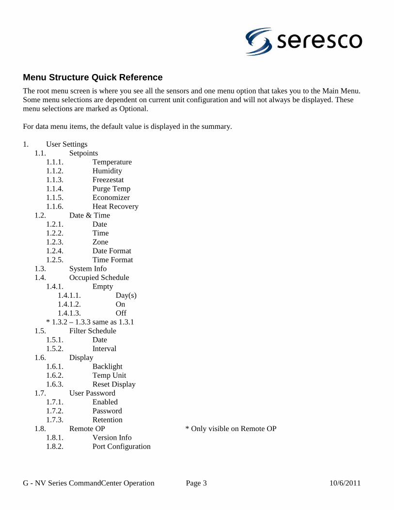
Menu Structure Quick ReferenceThe root menu screen is where you see all the sensors and one menu option that takes you to the Main Menu. Some menu selections are dependent on current unit configuration and will not always be displayed. These menu selections are marked as Optional.
For data menu items, the default value is displayed in the summary.
1. User Settings1.1. Setpoints
1.1.1. Temperature1.1.2. Humidity1.1.3. Freezestat1.1.4. Purge Temp1.1.5. Economizer1.1.6. Heat Recovery
1.2. Date & Time1.2.1. Date1.2.2. Time1.2.3. Zone1.2.4. Date Format1.2.5. Time Format
1.3. System Info1.4. Occupied Schedule
1.4.1. Empty1.4.1.1. Day(s)1.4.1.2. On1.4.1.3. Off
* 1.3.2 – 1.3.3 same as 1.3.11.5. Filter Schedule
1.5.1. Date1.5.2. Interval
1.6. Display1.6.1. Backlight1.6.2. Temp Unit1.6.3. Reset Display
1.7. User Password1.7.1. Enabled1.7.2. Password1.7.3. Retention
1.8. Remote OP * Only visible on Remote OP1.8.1. Version Info1.8.2. Port Configuration
G - NV Series CommandCenter Operation Page 3 10/6/2011

2. Alarms2.1. Current Alarms2.2. Alarm Log
3. System Control3.1. Start/Stop Blower3.2. System Restart3.3. System Status
3.3.1. Environment3.3.2. Ventilation3.3.3. Network3.3.4. Serial Ports3.3.5. Control Status
3.4. Purge
4. Factory Settings4.1. Ventilation
4.1.1. Options4.1.1.1. Purging4.1.1.2. Economizer4.1.1.3. Eco Offset OA4.1.1.4. Eco Offset DP4.1.1.5. Mod Steps4.1.1.6. Fire Reset
4.1.2. Exhaust Fans4.1.2.1. Fan 1 Capacity4.1.2.2. Unoccupied4.1.2.3. Occupied
4.1.3. Dampers4.1.3.1. Unoccupied4.1.3.2. Occupied4.1.3.3. OAD 1 Max4.1.3.4. OAD 2 Min4.1.3.5. OAD 2 Max
4.1.4. Timers4.1.4.1. Stabilize4.1.4.2. Freezestat 14.1.4.3. Freezestat 24.1.4.4. No Airflow4.1.4.5. VFD Delay4.1.4.6. Econo Stable
4.2. Space Control4.2.1. Room Temperature
4.2.1.1. Deg*Min On4.2.1.2. Deg*Min Off
G - NV Series CommandCenter Operation Page 4 10/6/2011

4.2.1.3. Setpoint Adj4.2.2. A/C
4.2.2.1. Sensor4.2.2.2. Deg*Min On4.2.2.3. Deg*Min Off
4.2.3. Heating4.2.3.1. Type4.2.3.2. Deg*Min On4.2.3.3. Deg*Min Off4.2.3.4. Sensor4.2.3.5. Mod Step Size4.2.3.6. Stage 2 On
4.2.4. Humidity4.2.4.1. Deg*Min On4.2.4.2. Deg*Min Off
4.2.5. Deadbands4.2.5.1. Air Temp Low4.2.5.2. Air Temp High4.2.5.3. Humidity Low4.2.5.4. Humidity High4.2.5.5. Heat Rec High4.2.5.6. SA Temp Low4.2.5.7. SA Temp High
4.3. Network4.3.1. TCP/IP
4.3.1.1. DHCP4.3.1.2. IP4.3.1.3. Mask4.3.1.4. GW4.3.1.5. DNS4.3.1.6. Link Monitor
4.3.2. Serial Ports4.3.2.1. Port B (RS-232)
4.3.2.1.1. User4.3.2.1.2. Baud Rate4.3.2.1.3. Databits4.3.2.1.4. Parity4.3.2.1.5. Flow Control4.3.2.1.6. Reply Delay
4.3.2.2. Port C (RS-485)4.3.2.2.1. User4.3.2.2.2. Baud Rate4.3.2.2.3. Databits4.3.2.2.4. Parity4.3.2.2.5. Echo Test
G - NV Series CommandCenter Operation Page 5 10/6/2011

4.3.2.3. Port D (RS-485)4.3.2.3.1. User4.3.2.3.2. Baud Rate4.3.2.3.3. Databits4.3.2.3.4. Parity4.3.2.3.5. Echo Test
4.3.3. WebSentry4.3.3.1. Enabled4.3.3.2. IP4.3.3.3. Port4.3.3.4. Comm Interval4.3.3.5. Comm Segment4.3.3.6. Stay Alive
4.3.4. BACnet [Optional]4.3.4.1. Enabled4.3.4.2. Interface4.3.4.3. Device ID4.3.4.4. Port4.3.4.5. Heartbeat
4.3.5. Modbus [Optional]4.3.5.1. Device ID
4.3.6. LON [Optional]4.3.6.1. Enabled4.3.6.2. Interface4.3.6.3. Refresh Rate
4.4. Inputs/Outputs4.4.1. Sensor Type
4.4.1.1. Return Air4.4.1.2. RA Humidity4.4.1.3. Outdoor Air4.4.1.4. OA Humidity
4.4.2. Sensor Usage4.4.2.1. Return Air4.4.2.2. RA Humidity4.4.2.3. RA Dew Point4.4.2.4. Outdoor Air4.4.2.5. OA Humidity4.4.2.6. OA Dew Point4.4.2.7. Supply Air4.4.2.8. Exhaust Air4.4.2.9. Blower VFD4.4.2.10. Exhaust VFD
G - NV Series CommandCenter Operation Page 6 10/6/2011

4.4.3. Sensor Calibration4.4.3.1. Return Air4.4.3.2. RA Humidity4.4.3.3. RA Dew Point4.4.3.4. Outdoor Air4.4.3.5. OA Humidity4.4.3.6. OA Dew Point4.4.3.7. Supply Air4.4.3.8. Exhaust Air4.4.3.9. Blower VFD4.4.3.10. Exhaust VFD
4.4.4. AO Polarity4.4.4.1. Modulated Heat4.4.4.2. Exhaust Fans4.4.4.3. OA Damper 14.4.4.4. OA Damper 2
4.4.5. Digital Inputs4.4.5.1. Blower On/Off4.4.5.2. Space Heater4.4.5.3. Occupied4.4.5.4. A/C Override4.4.5.5. Heat Override4.4.5.6. Freezestat4.4.5.7. Exhaust 1 OL4.4.5.8. Exhaust 2 OL4.4.5.9. Heat Rec OL
4.4.6. Sample Rates4.4.6.1. AI Samples4.4.6.2. AI Sample Rate4.4.6.3. Refresh Sens4.4.6.4. DI Samples4.4.6.5. DI Sample Rate
4.4.7. Assignments4.4.7.1. Analog Inputs
4.4.7.1.1. Return Air4.4.7.1.2. RA Humidity4.4.7.1.3. Supply Air4.4.7.1.4. Outdoor Air4.4.7.1.5. OA Humidity4.4.7.1.6. Exhaust Air
4.4.7.2. Analog Outputs4.4.7.2.1. Modulated Heat4.4.7.2.2. Exhaust Fans4.4.7.2.3. OA Damper 14.4.7.2.4. OA Damper 2
G - NV Series CommandCenter Operation Page 7 10/6/2011

4.4.7.3. Digital Inputs4.4.7.3.1. Blower On/Off4.4.7.3.2. Space Heater4.4.7.3.3. Occupied4.4.7.3.4. A/C Override4.4.7.3.5. Heat Override4.4.7.3.6. Freezestat4.4.7.3.7. No Airflow4.4.7.3.8. Dirty Filter4.4.7.3.9. Exhaust 2 OL4.4.7.3.10. Heat Rec OL
4.4.7.4. Digital Outputs4.4.7.4.1. Exhaust Damp 14.4.7.4.2. Exhaust Damp 24.4.7.4.3. RA Damper4.4.7.4.4. Heat Recovery4.4.7.4.5. System Status4.4.7.4.6. Network Dev
5. Service [Optional]5.1. Force Demands
5.1.1. Enabled5.1.2. Ventilation5.1.3. Occupied
5.2. Force Contacts5.2.1. Reset All5.2.2. Ventilation
5.2.2.1. Blower5.2.2.2. OA Damper 15.2.2.3. Exhaust Damp 15.2.2.4. OA Damper 25.2.2.5. Exhaust Damp 25.2.2.6. Exhaust Fans5.2.2.7. RA Damper5.2.2.8. Heat Recovery
5.2.3. Heating5.2.3.1. Heat Stage 15.2.3.2. Heat Stage 25.2.3.3. Modulated Heat
5.3. Network5.3.1. Ping5.3.2. Console
5.4. Clear Alarm Log5.5. Clear All Logs5.6. Commission
G - NV Series CommandCenter Operation Page 8 10/6/2011

5.6.1. Tested5.6.2. Commissioned
G - NV Series CommandCenter Operation Page 9 10/6/2011

Menu Structure DescriptionThis is a more detailed description of each menu item.
1. User Settings 1.1. Setpoints
If user password has been enabled, you will need to enter the password before you can change any setpoint.
1.2. Date & TimeIn this section you set system time properties. You can set the date, time and time zone. You can also set what date time format that should be used.
Date is always edited in Year-Month-Day syntax and the time is always edited in 24-hour clock format not matter what the format settings are.
Time zone can be set to -3:30, -4:00 to -10:00 and GMT time.
The following date formats are supported:
Y-M-D, D/M/Y, M/D/Y and Full.
The last format will be spelled out as Jan 1, 2006.
Clock is either a 12 or 24-hour clock.
Note that if the unit is connected to the Internet, you do not need to set the clock. The clock will automatically be synchronized with a time server. Time zone and date/time formats still needs to be set.
1.3. System InfoThe System Info screen lists some useful information when troubleshooting the system like Software and Board version, current IP and MAC address.
1.4. Occupied ScheduleIf user password has been enabled, you will need to enter the password before you can change the schedule.
You can enter up to 3 scheduled items. Each item determines when the room is Occupied by specifying a start time and a stop time. You also specify which day of the week the scheduled item applies (Monday-Sunday, Workdays, Weekends or All).
If there are conflicting items then the priority goes to day items (Monday-Sunday) followed by Workday and Weekends and last All. Use this to your advantage by specifying a default schedule
G - NV Series CommandCenter Operation Page 10 10/6/2011
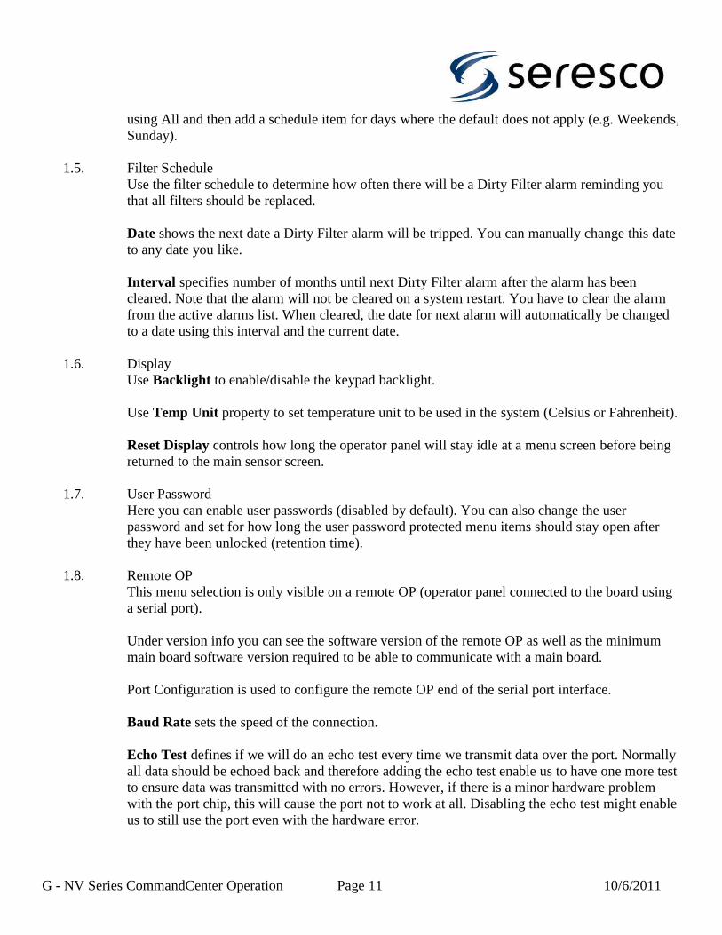
using All and then add a schedule item for days where the default does not apply (e.g. Weekends, Sunday).
1.5. Filter ScheduleUse the filter schedule to determine how often there will be a Dirty Filter alarm reminding you that all filters should be replaced.
Date shows the next date a Dirty Filter alarm will be tripped. You can manually change this date to any date you like.
Interval specifies number of months until next Dirty Filter alarm after the alarm has been cleared. Note that the alarm will not be cleared on a system restart. You have to clear the alarm from the active alarms list. When cleared, the date for next alarm will automatically be changed to a date using this interval and the current date.
1.6. DisplayUse Backlight to enable/disable the keypad backlight.
Use Temp Unit property to set temperature unit to be used in the system (Celsius or Fahrenheit).
Reset Display controls how long the operator panel will stay idle at a menu screen before being returned to the main sensor screen.
1.7. User PasswordHere you can enable user passwords (disabled by default). You can also change the user password and set for how long the user password protected menu items should stay open after they have been unlocked (retention time).
1.8. Remote OPThis menu selection is only visible on a remote OP (operator panel connected to the board using a serial port).
Under version info you can see the software version of the remote OP as well as the minimum main board software version required to be able to communicate with a main board.
Port Configuration is used to configure the remote OP end of the serial port interface.
Baud Rate sets the speed of the connection.
Echo Test defines if we will do an echo test every time we transmit data over the port. Normally all data should be echoed back and therefore adding the echo test enable us to have one more test to ensure data was transmitted with no errors. However, if there is a minor hardware problem with the port chip, this will cause the port not to work at all. Disabling the echo test might enable us to still use the port even with the hardware error.
G - NV Series CommandCenter Operation Page 11 10/6/2011

Reply Delay defines for how long we will wait for a reply message before considering it a communication fault.
2. Alarms 2.1. Current Alarms
The current alarm lists shows all alarms that have not been cleared. You can clear an alarm by selecting the alarm using number key and then pressing the Enter key to clear the alarm,
Note that some alarms are tied to a physical device that automatically will clear the alarm when device clear the fault condition. You can still clear this alarm from the alarm list but the alarm will trip right away if the device has not cleared the fault.
2.2. Alarm LogThe alarm log lists all alarms since the alarm log last was cleared (from the Service menu). Most recent alarm at the top. The top line shows the date for selected alarm.
Use arrow keys to select an alarm. Selected alarm is indicated by an arrow in the left margin. The alarm log will scroll one alarm at a time rather than a page at a time. If pressing the up key when the first alarm is selected, alarm log will be refreshed.
3. System Control 3.1. Start/Stop Blower
Start and stop main blower.
Note that the blower might not come when turning it on. There can be an alarm condition preventing it from starting (e.g. blower overload, voltage monitor fault or firestat).
When selecting Normal Mode at startup, the blower will automatically be started. To not run the blower you will have to go to this menu and turn blower off. There might be up to a minute delay before blower starts due to the voltage monitor fault signal not being cleared.
When selecting Service Mode at startup, the blower will not be started.
3.2. System RestartWhen selecting System Restart you will see a confirmation screen where you have to confirm that you want to restart the system. Pressing 2 or the Back button will cancel this request.
3.3. System StatusThe status screen shows the status for different internal system components. Its main purpose is for troubleshooting a running system where the information here can be passed back to tech support.
The status feature has been grouped into 6 areas.
G - NV Series CommandCenter Operation Page 12 10/6/2011

Environment shows status for the environment control (Air Temp and Humidity) including air heater.
The ventilation area shows the status of the different ventilation related components (including heat recovery).
The network area shows the status for network related components.
The serial ports area show serial port status.
The control status area shows internal control parameters.
3.4. PurgeBy selecting the Purge menu item you will get to the Purge activation screen. At this screen you can set the length of time the system will purge and start/stop purging.
At the bottom of the screen you can see the current status. It can show Off, PendingPurge or number of minutes remaining of ongoing purge.
PendingPurge means that we are waiting for the compressor(s) to stop before we can start purging. The compressors have been notified that they need to stop
Note that you only can start purge if Purge has been enabled under Factory Settings.
4. Factory Settings To access these settings you need to enter a service password.
4.1. Ventilation4.1.1. Options
Purging enables and disables the purging feature.
The Economizer property determines how the economizer feature will be used. Setting it to None disables the feature, setting it to A/C enables it for cooling only, setting it to Dehum enables it for dehumidification only and sertting it to Full enables it for bot cooling and dehumidification.
Eco Offset OA is an offset below return air setpoint. The return air setpoint minus this offset is the highest outdoor air temperature at which the economizer will start. The minimum outdoor air temperature is controlled by the economizer setpoint.
Eco Offset DP is an offset below return air dew point. The return air dew point minus this offset is the highest outdoor air dew point at which the economizer will start.
Mod Steps defines in how many steps the exhaust fans will ramp out from occupied mode fan speed to full speed.
G - NV Series CommandCenter Operation Page 13 10/6/2011

Fire Reset property controls how the system will recover after a Fire Alarm. When set to auto, system will automatically go back to normal once the alarm is cleared. When set to Manual, a System Restart is required to make the system operational again.
4.1.2. Exhaust FansFan 1 Capacity defines the fan 1 to fan 2 ratio. If both fans are the same size, leave at 50%. Otherwise determine in percentage the size of fan 1 compared to the size of both fans combined.
Unoccupied defines fan usage in unoccupied mode. Value based on total fan capacity.
Occupied defines fan usage in occupied mode. Value based on total fan capacity.
4.1.3. DampersUnoccupied defines OAD 1 position in unoccupied mode.
Occupied defines OAD 1 position in occupied mode.
OAD 1 Max defines OAD 1 position when exhaust fan runs at full speed. OAD 1 will modulate between occupied and max position as exhaust fan 1 changes speed.
OAD 2 Min defines the OAD 2 position when exhaust fan 2 runs at minimum speed. OAD 2 will modulate between min and max position as exhaust fan 2 changes speed.
OAD 2 Max defines the OAD 2 position when exhaust fan 2 runs at maximum speed.
4.1.4. TimersStabilize is how long time system will wait for sensors to stabilize after blower has started. No other components will start until sensors are stable.
Freezestat 1 is the Freezestat 1 alarm debounce timer. Freezestat 1 is tripped when supply air drops below the freezestat setpoint.
Freezestat 2 is the Freezestat 2 alarm debounce timer. Freezestat 2 is tripped if supply air drops stays below the freezestat setpoint after Freezestat 1 has been tripped.
No Airflow property is the No Airflow debounce timer.
VFD Delay property is used to control for how long unit will wait to start exhaust fan 1 after exhaust damper has started to open. This timer is also used for delaying purge fan 1 after purge damper has started to open.
Econo Stable property is a stabilizing timer used every time unit is increasing or reducing the number of purge fan stages.
G - NV Series CommandCenter Operation Page 14 10/6/2011

Purge Time is for how long time purge will run when started. Setting it to 0 means purge will run until manually stopped.
Dirt Filt Dly property is the Dirty Filter debounce timer if the dirty filter switch has been enabled.
4.2. Space Control4.2.1. Room Temperature
The Deg*Min On/Deg*Min Off properties controls for how long the control logic will wait until increasing or decreasing the supply air setpoint.
Setpoint Adj determines number of degrees to increase or decrease the supply air setpoint every time setpoint is changed.
4.2.2. A/CThe Sensor property determines how cooling will be controlled. Supply means that space temperature will be controlled by using supply air sensor only. Return means that the space temperature will be controlled by the Room Temperature controller using the return air sensor.
The Deg*Min On/Deg*Min Off properties controls for how long the control logic will wait until adding or removing a Cooling stage after a stage has been added/removed.
4.2.3. HeatingType sets heating type.
The Deg*Min On/Deg*Min Off properties controls for how long the control logic will wait until adding or removing a Heating stage after a stage has been added/removed.
The Sensor property determines how heating will be controlled. Supply means that space temperature will be controlled by using supply air sensor only. Return means that the space temperature will be controlled by the Room Temperature controller using the return air sensor.
Mod Step Size defines the increments for the modulated signal when heater is configured as a modulated heater.
Stage 2 On controls when the second stage digital output will be turned on for a modulated heater. First stage is turned on when heating is started.
4.2.4. HumidityThe Deg*Min On/Deg*Min Off properties controls for how long the control logic will wait until adding or removing a Dehumidification stage after a stage has been added/removed.
G - NV Series CommandCenter Operation Page 15 10/6/2011

4.2.5. DeadbandsThis section is used to configure setpoint deadbands. Air temperature deadbands can be set in 1/10th of a degree.
4.3. Network4.3.1. TCP/IP
Set DHCP to use Dynamic IP and set it to No to use Static IP. In the first case, the IP, Mask, GW and DNS property will be set automatically and you will be able to see what they are set to (as soon as a network connection has been detected and a DHCP server has been found).
IP is the systems IP address.
Mask is the network mask.
GW is the IP address for the gateway.
DNS is the IP address for the Domain Name Server.
Link Monitor is how often the system will check that there still is a physical network link. If you unplug the Ethernet cable, it can take up to this time before it is detected.
Start Device is a timer that is used at startup of a network device. The Network Device digital output has to be assigned to a terminal. Regular network setup will not start until this timer expires.
Reboot Device is the number of minutes the network can be down until unit will reboot the network device (if assigned to a terminal). Reboot means turning off Network Device output and then turning it back on.
Reboot Delay is how long the network device will stay off on a reboot request before turning it back on again.
4.3.2. Serial PortsPort properties are the same for all ports except where noted.
User defines the user of the port. Default is Seresco which means the port is opened for inbound traffic using the Seresco protocol. Other users are other protocols like LON and Modbus as well as 3&4 compressor slave board communication.
Baud Rate, Databits and Parity defines your common serial port configuration parameters.
Flow Control defines if hardware flow control should be used. Can only be configured for the RS-232 port (port B).
G - NV Series CommandCenter Operation Page 16 10/6/2011

Echo Test defines if we will do an echo test every time we transmit data over the port. Normally all data should be echoed back and therefore adding the echo test enable us to have one more test to ensure data was transmitted with no errors. However, if there is a minor hardware problem with the port chip, this will cause the port not to work at all. Disabling the echo test might enable us to still use the port even with the hardware error.
Reply Delay defines for how long we will wait for a reply message before considering it a communication fault.
4.3.3. WebSentryThese properties controls WebSentry connection.
Set Enabled to No to disable WebSentry. You can do this if you temporarily want to disable WebSentry connections. Also you should do this if a unit is not connected to the Internet to avoid unnecessary attempts trying to detect a physical network link.
IP is the WebSentry server IP address. Use this property to configure the IP address or to see what it is if DNS is enabled.
Port is the WebSentry port to connect to. This is configurable in case the port will change in the future.
Comm Interval is how often the system will try to connect to the WebSentry server between disconnects.
Comm Segment is how often the system will try to connect to the WebSentry server between disconnects when we can not transmit all non-sent data in one session.
Stay Alive is how long the TCP connection will stay active from the last time a message was received from the WebSentry server. Normally the WebSentry server should disconnect before this time.
4.3.4. BACnetThese properties controls BACnet connections and are only available if the CommandCenter has been loaded with BACnet support.
Set Enabled to Yes to enabled BACnet. It is disabled by default.
Set Interface to BACnet interface type. Currently only Ehernet and IP is supported.
Use Device ID to set a unique device ID for unit on the BACnet network.
Port can be used to change the default port setting.
G - NV Series CommandCenter Operation Page 17 10/6/2011

The Heartbeat timer is used when BACnet interface is controlling some sensors. If no message is received within this time, unit will rollback to system installed sensors. Setting timer to 0 means that timer will not be used.
4.3.5. ModbusUse these properties to configure Modbus communication.
4.3.6. LONUse these properties to configure LON-Modbus gateway communication.
Set Enabled to ReadWrite to enable LON for read and write support. Set it to ReadOnly to only let LON interface read data from unit (no changes allowed).
Use Interface to define which serial port to use for gateway communication.
Refresh Rate defines how often unit will check gateway for changed data.
4.4. Inputs/Outputs4.4.1. Sensor Type
The sensor types controls how an input signal is translated into a value. Note that some sensors that are available under sensor calibration are not available under sensor types. These are temperature sensors for which there are no other sensor type that can be used except Thrm.
The following sensor types are available:• Thrm, thermistor sensor to be used for all temperature sensors.• GSRA, Greystone return air sensor.• GSRH, Greystone RH sensor.• RH, General RH sensor.• SG145, Saginomiya transducer, max 145 psi.• SG200, Saginomiya transducer, max 200 psi.• SG435, Saginomiya transducer, max 435 psi.• SG500, Saginomiya transducer, max 500 psi.• JC100, Johnson Controls transducer, max 100 psi.• JC500, Johnson Controls transducer, max 500 psi.• BMS, Building Management System controlled sensor.• Calc, Calculated sensor.
4.4.2. Sensor UsageThe sensor usage option determines how a sensor is being used.There are four values that can be set.
None will disable sensor. It will not be used for control and will not be displayed on sensor screen.
G - NV Series CommandCenter Operation Page 18 10/6/2011

Dflt is the default setting for most sensors. It means that that sensor will be used as determined by the system. For sensors used for control, sensor will used both for control and it will also be displayed on sensor screen.
Set sensor to View to disable sensor for control but still have it displayed on sensor screen.
Set sensor to Ctrl to not show it on sensor screen but still have it enabled for control.
4.4.3. Sensor CalibrationAll sensor calibration values are changed the same way. You usethe up and down arrow to change the value to a few steps above orbelow 0.
4.4.4. AO PolarityThese options are used to set the polarity of the analog outputs. 0V means that device is off or closed at 0 volts. 10V means that device is off or closed at 10 volts.
4.4.5. Digital InputsThese options are used to enable/disable some digital inputs. Several of them are optional inputs that can be used to control certain components and features of the system.
4.4.6. Sample RatesThe AI Samples and AI Sample Rate properties are used to fine tune the way analog inputs are read and translated into sensor readings. A sensor reading is the average of all read samples.
Refresh Sens property sets how often sensors will be read. Sensor reading will also be generated when there is a change in the sensor reading. Refreshing sensors on a regular basis prevents us from getting stuck with no sensor readings for a long time when the system is stable.
The DI Samples and DI Sample Rate properties are used to fine tune the way digital inputs are read and translated into alarms or other inputs. A digital input will signal a state change when all samples are the same and are different from current saved state.
4.4.7. AssignmentsThese settings are used to assign an input or output signal to a physical input/output on the board. The internal input/output id is being used to reference the physical input/output. A wiring diagram is needed to determine the board terminal.
5. Service To reach these settings you need to enter a service password.
G - NV Series CommandCenter Operation Page 19 10/6/2011

5.1. Force DemandsUse Force Demands to test the full functionality of the exhaust fans. This feature simulates demands from higher level control when unit is running in normal mode.
To use this feature you first have to enable it using the Enabled option. When setting Enabled to Yes, all contacts are reset followed by starting the main Blower.
It is highly recommended not to use Force Contacts when using Force Demands. Especially compressor related contacts.
Ventilation demand is changed by either increasing or reducing a demand. Select demand and press up button to increase demand or down button to increase demand.
The Ventilation demand will show the current exhaust level in percentage of full capacity.
Use Occupied option to bring exhaust fans into unoccupied mode or occupied mode.
5.2. Force ContactsForce Contacts is used to test all the Analog and Digital Outputs. This overrides any internal control of corresponding features and is just a way to physically test that a contact is working.
Selecting Reset All will reset all contacts back to the Off position.
5.3. Network5.3.1. Ping
The ping feature is used to test the IP network.
To use ping, set the ping address and then select start. The first result line shows the IP addresses you are pinging from (units IP address) and the second line will show 4 time values in milliseconds.
Ping will send 4 messages to specified address and measure in milliseconds how long it will take to get a reply. If no reply within 5 seconds the result will show Fail for that particular ping request.
5.3.2. ConsoleThe console is currently only used to monitor serial port messages. Select the serial port to monitor by using the arrows keys. Select 1 to start monitoring. To stop/pause messages, you can press key 2 anytime. Press Enter to clear the screen. Select back top stop console or to go back and select another serial port.
5.4. Clear Alarm LogSelecting Clear Alarm Log will display a confirmation screen where you have to confirm that you want to clear the alarm log. Pressing 2 or the Back button will cancel this request.
G - NV Series CommandCenter Operation Page 20 10/6/2011

5.5. Clear All LogsEven though you only can look at the alarm log from the control panel, there are several other logs used as well. These logs can be read using WebSentry if the unit is connected to Internet.
Use Clear All Logs to clear all the logs and not just the alarm log.
5.6. CommissionWhen control board initially is configured loaded with the latest control software, unit is prepared to make it safe and easy to use when testing unit before delivery to customer. When test completed, the Tested option is changed to Yes and can never be changed back again.
When unit has been tested, the compressor Enabled property will be changed to No.
When Commissioned option still is set to No, unit will start up in service mode. It is not possible to start the unit in Normal Mode. The blower can be started anytime but to enable the compressors and to be able to change the Commissioned option, a factory password is required.
When changing Commissioned to Yes, all the logs will be cleared and the unit will do a system restart. Now at startup you will see the normal startup screen with 2 selections, Normal Mode and Service Mode.
The Commissioned option can be changed back to No if needed.
G - NV Series CommandCenter Operation Page 21 10/6/2011

Issue Date : 2011-10-06 Section H - Routine Maintenance (NV Series)
Routine Maintenance
WARNING Disconnect all electrical power, including remote disconnect, and discharge all
energy storing devices before servicing. Follow proper lockout procedures to ensure the power cannot be
accidentally energized. Failure to follow provided safety warnings and labels could result in serious injury
or death.
WARNING When it is necessary to work with live electrical components, have a licenced
electrician or other qualified persons perform the required maintenance.
WARNING Danger or moving mechanical parts, high voltage power, elevated pressure and
temperature ! When performing maintenance activities, lock out the unit to prevent accidental start-up.
When service is required, call a qualified refrigeration mechanic.
Routine Maintenance Checklist
Seresco Technologies Inc.'s products are built for dependable and safe operation with minimum maintenance. Periodic
maintenance is required, however, to ensure continuous safety and maximum operating efficiency. Suggested maintenance
operations are listed in the table below with the recommended service intervals. Please note that these are general guidelines
and should be adjusted accordingly to match facility operating conditions.
Table 1. Routine Maintenance Requirements
Frequency Maintenance Operation
Weekly Observe unit weekly for any change in running condition and unusual noise
MonthlyClean or replace air filters if clogged or dirty
Verify that all set-points are correctly programmed as specified by the facility operator
Quarterly
Inspect and clean drain pans
Tighten electrical connections if required
Check and tighten, if required, sensor mounts
Inspect coils for dirt build-up
Check that the P-trap is primed (filled with water). It is good practice to to pour some water into
the drain pan to ensure that the P-trap is primed and operational
Check and lubricate motor bearings. Refer to the motor manufacturer's instructions
Check outdoor air louvres for accumulation of dust and clean as required
H-1

Section H - Routine Maintenance (NV Series) Issue Date : 2011-10-06
Yearly
Inspect the unit casing for corrosion. If damage is found, clean and repaint the affected surface with a rust-resistant primer
Clean the fan wheel(s) and motor shaft(s)
Inspect and clean drain pans
Check damper operation
Inspect electrical components, wiring and insulation
Rotate the fan wheel(s) and check for obstructions and rubbing
Lubricate motors as directed by motor manufacturer
Check gasket condition on all doors to ensure an airtight seal
Check for loose external or internal parts, paying careful attention external components
Check bolts on motor mounts, unit bases and coils and tighten if required
Component Maintenance
Filters
Replace filters when dirty. Check filters located in main filter wall, outside air intake and exhaust fan opening. Filters should
slide out of their tracks without difficulty. Replace with filters of equivalent size and rating. See section Z - Annex for filter
sizes and quantities.
Drain Pans
WARNING Hazardous chemicals ! Cleaning agents can be highly acidic or alkaline. Handle all
chemicals carefully and use appropriate personal protective equipment (PPE). Refer to the cleaning agent
manufacturer's Materials Safety Data Sheet (MSDS) for safety and handling information. Failure to follow
all safety instructions could result in serious injury or death.
Note : Do not walk on the drain pans. Doing so will cause damage and impair drainage.
To clean drain pans:
1. Disconnect all electrical power to the unit
2. Remove any standing water
3. Scrape solid foreign material off of the drain pan and vacuum to remove particulate matter
4. Thoroughly clean any contaminated area(s) with a mild bleach and water solution or an EPA approved
H-2

Issue Date : 2011-10-06 Section H - Routine Maintenance (NV Series)
sanitizer designed for HVAC use. Immediately rinse with fresh water to prevent corrosion
5. Allow to dry completely before putting the unit back into service. Dispose of all contaminated
materials
Impellers / Fans
To clean fan blades:
1. Disconnect all electrical power to the unit
2. Scrape solid foreign material off of the fan blades and vacuum to remove particulate matter
3. Thoroughly clean any contaminated area(s) with a mild bleach and water solution or an EPA approved
sanitizer designed for HVAC use. Immediately rinse with fresh water to prevent corrosion
4. Allow to dry completely before putting the unit back into service. Dispose of all contaminated
materials
Motors
Inspect fan motors periodically for excessive vibration or temperature. For bearing lubrication and other maintenance
activities, see manufacturer's literature provided in the appendix.
Coils
WARNING Hazardous pressures ! Coils containing refrigerant under pressure must not be
cleaned using a solution over 150 ºF. Failure to follow these safety precautions could result in coil bursting,
which could result in serious injury or death.
To clean coils:
1. Disconnect all electrical power to the unit
2. Wearing the appropriate personal protective equipment (PPE), use a soft brush to remove loose debris
from the coil
3. Install a block-off to prevent spray from going through the coil and into a dry section of the unit and /
or system ductwork
4. Mix a high quality coil cleaning detergent with water according to the manufacturer's instructions
5. Place the mixed solution in a garden pump-up sprayer or high-pressure sprayer. If a high-pressure
sprayer is to be used:
H-3

Section H - Routine Maintenance (NV Series) Issue Date : 2011-10-06
a) Maintain minimum nozzle spray angle of 15 degrees
b) Spray perpendicular to the coil face
c) keep the nozzle at least 6 inches from the coil
d) Do not exceed 60 psi
6. Spray the leaving side of the coil first, then the entering air side
7. Thoroughly rinse both sides of the coil and the drain pan with cool, clean water
8. Straighten any coil fins that have been bent during the cleaning process
9. Confirm the drain line is clear
10. Replace all panels and parts and restore electrical power to the unit
11. Dispose of all contaminated materials
Insulation
Note : Microbial growth ! Wet interior insulation can become an amplification site for microbial growth
(mold), which may cause odours and damage to the equipment and building materials. If there is evidence
of microbial growth on the interior insulation, the insulation should be removed and replaced prior to
operating the system.
Accumulated dirt and other organic matter exposed to water or extended periods of high relative humidity (60 percent or
higher) can support microbial growth, which must be removed to prevent the unit from becoming a contaminant source. If
evidence of contamination exists, determine and eliminate the cause, remove the contamination and sanitize the affected
area.
H-4

Issue Date : 2011-10-06 Section H - Routine Maintenance (NV Series)
Outdoor Air Balancing
The amount of outdoor air introduced into the unit varies by season. Seresco Technologies Inc. provides manual balancing
dampers with all outdoor air equipped units. Even if a unit mounted motorized air damper is installed, the manual damper
will also be installed. There are two types of manual dampers depending on the size of the unit.
NE/NP-004 to -016 and NE/NP-2xx Series
Note that the Outdoor Air filter box contains two perforated sliding plates as shown in Figure H-1. Adjust the manual
damper by turning the black knob to slide one plate along the other. Align the holes for maximum air flow or misalign the
holes to block or dampen the airflow.
Figure H-2. Outdoor Air Filter Box
For NE/NP/NV-018 to NE/NP/NV-120
To adjust the outdoor air balance, first remove the filters. The manual damper consists of two perforated plates, one of which
slides on top of the other. To adjust the air balance loosen all the screws and slide the plate to obtain the desired setting. Re-
tighten all the screws.
H-5

Section H - Routine Maintenance (NV Series) Issue Date : 2011-10-06
Figure H-3. Outdoor Air Filter Box
Figure H-4. Outdoor Air Tightening Screw (highlighted)
H-6

Issue Date : 2011-09-20 Section X - Troubleshooting
Troubleshooting
This section is intended to be used as a diagnostic aid only. For detailed repair procedures, contact Seresco Technologies
Inc.'s service department.
Two user-friendly service tools are critical in troubleshooting any issues with Seresco's dehumidification systems: the
WebSentry remote monitoring software and automated system alarm logs. WebSentry remote monitoring software allows
the collection of comprehensive unit performance data and space conditions via the Internet. This option is default on all
units with CommandCenter controls and has proven to be an extremely effective service tool. To function correctly, this
requires the unit to be connected to a local network with Internet access. System Alarm Logs detail information on alarm
situations, including the type of alarm, faults and time to help service technicians narrow down possible cause(s) of the
problem(s).
Troubleshooting Steps
1. Collect information from unit owner/maintenance team about problem(s)
2. Refer to the provided Installation, Operation and Maintenance manual and the unit label for additional
information
3. Perform a basic visual inspection of the unit
4. Check the System Alarm Log for the latest alarm(s)
CAUTION If the unit is powered down: before powering up the system again, ensure that it is safe
to do so.
5. Refer to the list of common problems provided below for probable causes and suggested solutions
6. If you require further assistance, please feel free to contact Seresco's Service and Technical Support (STS)
department
Contacting Seresco Service and Technical Support (STS)
The next availible service technician can be reached by phone at (613)-741-3603, followed by 2, or by e-mail at
[email protected]. When contacting Seresco STS, please have the following information on hand:
− Your name
− Service company name
− Phone number
− Seresco unit serial number (8 digit number on the unit label i.e. 11011800)
X-1

Section X - Troubleshooting Issue Date : 2011-09-20
WebSentry Connection Troubleshooting Guide
Ethernet cable connected and operating
First thing to check is that the Ethernet cable has been hooked up properly and is operating normally. Use the LED’s by the
Ethernet socket to verify this. The LED’s are the two white square components on the mini board with the Ethernet socket.
The one closest to the socket should be solid green and indicates a solid physical connection. Unplug cable at the unit or at
the other end and this LED will go blank.
If cable is connected at both end and the LED still does not lit up, it is very possible the Ethernet socket itself is faulty.
Connecting a network cable between a laptop and unit can determine that indeed the Ethernet socket is faulty and that there
is not a faulty router port or faulty cable.
The second LED is yellow and will blink when there is communication.
Firewall settings
The unit will try to connect to the WebSentry server once a minute using port 1030. Server name is websentry.seresco.net.
Use ping to determine IP address associated with this IP address if this is needed for any firewall settings.
If network has a firewall, port 1030 must be open for communication or at least for the IP assigned to unit or the MAC
address for the unit or to/from the Seresco domain name or server IP.
The MAC address can be found under System Info using the local keypad. ‘*’ translates to 00:90:C2 so that if MAC shows
*:D1:2A:49 the full MAC address is 00:90:C2:D1:2A:49.
Checking network communication status
Check status of network communication from the local keypad. From main screen select Main Menu (1) - System (3) -
System Status (5) - Network (4).
TCP/IP should be saying Up. If it says PendingUp, there is a problem with establishing a physical connection. Network
cables and router/switch needs to be checked. Ensure light over port where unit is connected is lit up.
WebSentry will say Idle when waiting to connect to server (connects once a minute). When connected you will either see
Receive or Send. If it shows Connecting for several seconds it means there is a problem establishing a connection to the
server. Usually it will toggle between Idle and Connecting when a proper connection is not established. Check TCP/IP and
WebSentry configuration settings.
X-2

Issue Date : 2011-09-20 Section X - Troubleshooting
Checking TCP/IP configuration settings
Unit can be configured for dynamic or static IP. From main screen select Main Menu (1) - Factory Settings (5) - Network (5)
- TCP/IP (1). If asked for a password at Factory Settings selection, enter 813.
DHCP set to Yes is for dynamic IP and if set to no, unit is configured for Static IP.
Dynamic IP
You should see an IP and Mask assigned (* means 255). This is assigned by the router to which the unit is connected. On
second page you should also see IP's assigned to GW (Gateway) and DNS.
If any of these IP’s are not assigned properly (showing 0.0.0.0 for instance), there is a problem with the router assigning IP
info to the unit.
Static IP
IP, Mask, GW and DNS all have to be configured correctly or unit will not be able to communicate with the WebSentry
server. This information should be known by the IT group managing the local network.
Check WebSentry configuration settings
By default the unit is configured to use DNS (Domain Name Server) to translate the Seresco domain name to the
appropriate WebSentry IP address. Before software version 4.8.0, domain name www.seresco.net was used. Starting from
version 4.8.0, domain name websentry.seresco.net is used.
If the IP is changing between an IP address and 0.0.0.0, there is a problem with the domain name lookup. In this case you
can try to configure a static IP for the WebSentry server.
Change Use DNS to No and then change the IP address to IP of websentry.seresco.net (currently 97.74.200.218).
Testing Internet access from unit
Unit has a Ping feature that can be used to test that unit can connect to any IP address on the local network as well as to any
IP over Internet.
To use the Ping feature you have to start the unit in Service Mode. From main screen select Main Menu (1) - System (3) -
System Restart (3) and then press Yes (1) to confirm.
When unit starts up you will have a selection menu. Select Service (2).
X-3

Section X - Troubleshooting Issue Date : 2011-09-20
To access the Ping feature, select Main Menu (1) – Service (6) – Network (3) – Ping (1). If asked for a password at Service
selection, enter 813.
To test connection to WebSentry server, make sure IP (selection 1) is set to 97.74.200.218. Press 2 to start Ping request.
The 3rd line shows the current IP address assigned to the unit. The 4th line will either have 4 time values or the text Fail (up
to 4 times). The time values indicate number of milliseconds for Ping message to go to WebSentry server and back.
Testing Internet access and WebSentry access from unit Ethernet cable
A simple test you can do to make sure there is Internet access from the Ethernet cable connected to our unit is to connect
this cable into a laptop and accessing any web site using a web browser.
If unit is configured for static IP, you should configure the laptop with the exact same TCP/IP configuration. How this is
done is not covered in this document.
IMPORTANT! Make sure WiFi connection is disabled when testing Ethernet cable.
A secondary test to ensure you can communicate with the Seresco WebSentry server is to use the Telnet command to
establish a connection to the server.
Open up the Command Prompt window. Enter the command:
telnet 97.74.200.218 1030
You should now see a blank screen with a prompt. Hit any two characters. The text Seresco WebSentry should now be
displayed followed by Connection to host lost. This verifies that you can open up a connection to the port used by the
WebSentry server and that this port is not blocked by any firewall.
If the connection failed it most likely is a firewall issue. Port 1030 must be open for communication or at least for the IP
assigned to the Seresco unit.
Contact Factory
If everything in this document has been tested and everything indicates that the communication should be working, we are
dealing with an unknown fault. Contact Seresco for further advice.
X-4

Issue Date : 2011-09-30 Section Y - Warranty
Warranty
General Policy
This warranty applies to the original equipment owner and is not transferable. Seresco Technologies Inc.
warrants as set forth and for the time periods shown below that it will furnish, through a Seresco Technologies
Inc. authorized installing contractor or service organization, a new or rebuilt part for a factory installed part
which has failed because of defect in workmanship or material.
Warranty Void Unless Registered
Warranty is void unless, upon start-up of the unit, the “Warranty Registration and Start-up Report” is
completed and sent to the factory within one week of initial start-up. This report will also register the
compressor warranty with the compressor manufacturer.
Initial 90-day Warranty
During the first 90 days from initial start-up and prior to the completion of the 24th month from date of
shipment, whichever comes first and subject to prior written approval from the factory, Seresco Technologies
Inc. will provide and/or reimburse the required labour, materials, and shipping and handling costs incurred in
the replacement or repair of a factory installed defective part. Only the labour required to replace the defective
part is warrantied – travel time, diagnostic time, per diems, truck charges, etc. are not covered under this
warranty.
WebSentry Conditional One Year Extended Labour Warranty
The factory labour warranty shall be extended for a total of 12 months from initial start-up and prior to the
completion of the 24th month from date of shipment, whichever comes first and subject to prior written
approval from the factory. The provided equipment must be connected and communicating to Seresco's
WebSentry online control and monitoring service for the entire term of the warranty extension. Seresco
Technologies Inc. will provide and/or reimburse the required labour, materials, and shipping and handling
costs incurred in the replacement or repair of a factory installed defective part. Only the labour required to
replace the defective part is warrantied – travel time, diagnostic time, per diems, truck charges, etc. are not
covered under this warranty.
Two Year Parts Warranty
If any factory installed part supplied by Seresco Technologies Inc. fails because of a defect in workmanship or
material prior to the completion of the 24th month from date of shipment, Seresco Technologies Inc. will
Y-1

Section Y - Warranty Issue Date : 2011-09-30
furnish a new or rebuilt part F.O.B. factory. No labour reimbursement will be made for expenses incurred in
making field adjustments or parts replacement outside the Initial 90-day Warranty. Seresco Technologies Inc.
reserves the right to have the defective part returned to the factory in order to determine the warranty
applicability. Parts shipping and handling costs (to and from the factory) are not covered outside of the Initial
90-day Warranty.
Replacement Part Warranty
If a replacement part provided by Seresco Technologies Inc. under this warranty fails due to a material defect
prior to the end of the Two Year Parts Warranty (or the end of the extended warranty period if applicable) or 12
months from date of the replacement part shipment, whichever comes first, Seresco Technologies Inc. will
furnish a new or rebuilt part F.O.B. factory.
Applicability
This warranty is applicable only to products that are purchased and installed in the United States and Canada.
This warranty is NOT applicable to :
1. Products that have become defective or damaged as a result of the use of a contaminated water
circuit or operation at abnormal water temperatures and/or flow rates
2. Parts that wear out due to normal usage, such as air filters, belts and fuses. 2. Refrigerant lost during
the parts warranty will be reimbursed in accordance to the current market price of refrigerant at the
time of repair. Seresco Technologies Inc. will not be responsible for refrigerant lost from the system
due to improperly installed contractor piping to the remote outdoor air cooled condenser.
3. Refrigerant coils that corrode due to improperly balanced pool chemistry or corrosive air quality.
4. Components that have been relocated from their original placement at the factory.
5. Any portion of the system not supplied by Seresco Technologies Inc.
6. Products on which the model and/or serial number plates have been removed or defaced.
7. Products which have become defective or damaged as a result of unauthorized opening of
refrigeration circuit, improper wiring, electrical supply characteristics, poor maintenance, accidents,
transportation, misuse, abuse, fire, flood, alteration and/or misapplication of the product.
8. Products not installed, operated and maintained as per Seresco Technologies Inc. Owner’s Manual.
9. Products on which payment is in default.
Limitations
This warranty is given in lieu of all other warranties. Anything in the warranty notwithstanding, any implied
warranties of fitness for particular purpose and merchantability shall be limited to the duration of the express
warranty. Manufacturer expressly disclaims and excludes any liability for consequential or incidental damage
Y-2

Issue Date : 2011-09-30 Section Y - Warranty
for breach of any express or implied warranty.
Where a jurisdiction does not allow limitations or exclusions in a warranty, the foregoing limitations and
exclusions shall not apply to the extent of the legislation, however, in such case the balance of the above
warranty shall remain in full force and effect.
This warranty gives specific legal rights. Other rights may vary according to local legislation.
Force Majeure
Seresco Technologies Inc. will not be liable for delay or failure to provide warranty service due to government
restrictions or restraints, war, strikes, material shortages, acts of God or other causes beyond Seresco
Technologies Inc. control.
Optional Five Year Compressor Warranty
This extended warranty must be purchased before the shipment of the unit.
Seresco Technologies Inc. will provide a replacement compressor for 60 months from the date of shipment
provided the factory installed compressor fails as a result of manufacturing defect and is returned to the factory
with transportation prepaid. This extended compressor warranty is subject to all the terms of the standard
Seresco Technologies Inc. warranty but applied to the compressor only.
No charges attributed to the replacement of a component, except as detailed in above Initial 90-day Warranty,
will be allowed unless specifically granted in writing beforehand by Seresco Technologies Inc.
Optional Five Year Airside Coil Warranty
This extended warranty must be purchased before the shipment of the unit.
Seresco Technologies Inc. will provide a replacement Airside Coil for 60 months from the date of shipment
provided the failed coil is returned to the factory with transportation prepaid. This extended coil warranty is
subject to all the terms of the standard NE Series warranty but applied to the coil only.
No charges attributed to the replacement of a component, except as detailed in above Initial 90-day Warranty,
will be allowed unless specifically granted in writing beforehand by Seresco Technologies Inc.
This warranty is contingent to the proper maintenance of pool water chemistry including a pH of between 7.2
and 7.6 free chlorine not exceeding 2.0 ppm and combined chlorine maintained at less than 0.3 ppm. These
Y-3

Section Y - Warranty Issue Date : 2011-09-30
parameters are to be measured and recorded daily and be available for review upon request.
Optional 10 Year Airside Coil Warranty
This extended warranty must be purchased before the shipment of the unit.
Seresco Technologies Inc. will provide a replacement Airside Coil for 120 months from the date of shipment
provided the failed coil is returned to the factory with transportation prepaid. This extended coil warranty is
subject to all the terms of the standard NE Series warranty but applied to the coil only.
No charges attributed to the replacement of a component, except as detailed in above Initial 90-day Warranty,
will be allowed unless specifically granted in writing beforehand by Seresco Technologies Inc.
This warranty is contingent to the proper maintenance of pool water chemistry including a pH of between 7.2
and 7.6 free chlorine not exceeding 2.0 ppm and combined chlorine maintained at less than 0.3 ppm. These
parameters are to be measured and recorded daily and be available for review upon request.
Optional Five Year Driveline Warranty
This extended warranty must be purchased before the shipment of the unit.
Seresco Technologies Inc. will provide a replacement part for the following components:
Supply fan motor
Supply fan motor starter
Exhaust fan motor
Exhaust fan motor starter
Pool water heater solenoid valves & valve coils
Liquid expansion solenoid valves & valve coils
Air-cooled condenser solenoid valves & valve coils
Blowers
Driveline warranty exists for 60 months from the date of shipment provided the factory installed component
fails as a result of manufacturing defect and is returned to the factory with transportation prepaid. This
extended driveline warranty is subject to all the terms of the standard Seresco Technologies Inc. warranty but
applied to the listed parts only.
No charges attributed to the replacement of a component will be allowed unless specifically granted in writing
beforehand by Seresco Technologies Inc.
Y-4

Issue Date : 2011-09-30 Section Z - Annex
Unit Component Specifications
&
Component Service Sheets
Z-1

Issue Date : 2011-09-30 Z - Startup Report
Startup Report - Seresco Technologies Inc.
Project Name NE Series Model
Location Serial Number
Site Contact/Tel: Seresco Rep.
Unit Visual Inspection
Check Comments
Supply air blowing on exterior doors and windows?
No supply-return air short-circuiting?
Outdoor air connected to Seresco unit?
Exhaust fan installed and operating, away from intake?
Vapor Barrier installed?
Condensate P-Trap installed and filled?
Condensate line tested?
Pool Water piping properly installed?
Auxiliary pool water circulating pump installed?
Pool water flow to spec?
OACC or Dry Cooler installed and wired properly?
Nameplate voltages verified?
Main disconnect installed?
Wiring connections checked & tightened?
Control wiring to aux pool heater installed?
Floor drain in mechanical room?
Chemicals stored in separate ventilated room?
Air balance report on file?
List other external controlled components
WebSentry connected?
Blowers, compressors rotation checked?
Adequate service access provided?
Unit’s leveled and vibration isolated?
Flex connectors used at both duct connections?
What type of refrigerant is used?
** TO VALIDATE WARRANTY FILL OUT AND FAX to 1-613-741-3375 ** 1 of 4

Z - Startup Report Issue Date : 2011-09-30
Unit Electrical Data
L1 – L2 L1 – L3 L2 – L3 Nameplate
Unit Voltage (V)
Transformer secondary voltage (V)
Compressor 1 (A)
Compressor 2 (A)
Main Blower 1 (A)
Main Blower 2 (A)
Exhaust Blower 1 (A)
Exhaust Blower2 (A)
Purge Blower 1 (A)
Purge Blower 2 (A)
OACC Motor 1 (A)
OACC Motor 2 (A)
OACC Motor 3 (A)
OACC Motor 4 (A)
Heat Recovery Pump (A)
Hot Water Pump (A)
Hot Water Pump 2(A)
NOTE: Put ALL additional info/comments into Notes section.
Outdoor Air Condensing / Cooling Unit inspection
Check Comments/Data
OACC or dry cooler located how feet above/below/level with
Seresco Unit?
Oil traps installed for OACC?
Model number of condenser
Field charge added in pounds and refrigerant type
Fluid GPM
Glycol %
Glycol stabilizers added?
Distance from Seresco Unit to OACC or dry cooler (one-way line length), ft
Hot gas line size (in)
Liquid line size (in)
Pipe size to dry cooler (in)
2 of 4 For tech support call: 1-770-457-3392 ext.2# OR 1-613-741-3603 ext.4#

Issue Date : 2011-09-30 Z - Startup Report
Fluid Temperature entering main unit (F)
Fluid Temperature leaving main unit (F)
Piping and valves installed per spec?
Unit Operating Data and Configurations
Operating Data Unit Configuration
Sensor Reheat Reheat +
Pool heat
A/C A/C +
Pool heat
Setpoints Value
Return Air (F) Return Air (F)
Return Air (% RH) Return Air (RH)
Supply Air (F) Pool 1 (F)
Pool 1 In (F) Pool 2 (F)
Pool 1 Out (F) Purge (F)
Pool 2 In (F) HR (F)
Pool 2 Out (F) Economizer (F)
Outdoor Air (F)
Comp 1 HP (psi) Air Heating Type
Comp 1 LP (psi) Clock Set?
Comp 1 Suction (F) Board #
Comp 1 Discharge (F) MAC address
Evap 1 (F) IP address
Superheat 1 (F)
Comp 2 HP (psi) BACNET?
Comp 2 LP (psi) LON?
Comp 2 Suction (F) MODBUS?
Comp 2 Discharge (F)
Evap 2 (F)
Superheat 2 (F) NOTE: Check/verify superheat is within 18 – 22 F margin; refer to
Pressure -Temperature chart for proper refrigerant. Adjust if required.
Exhaust (F)
Reheat (F)
T/B Sight Glasess1
T/B Sight Glasses 2 NOTE: For Receiver Sight glasses:T(top)/B(bottom) make note whether
ball is “UP” or “DOWN”. Moisture Indicator 1
Moisture Indicator 2
** TO VALIDATE WARRANTY FILL OUT AND FAX to 1-613-741-3375 ** 3 of 4

Z - Startup Report Issue Date : 2011-09-30
Startup Date
Startup Company Name
Startup Company Contact #
Startup Technician Name
Startup Technician Contact #
Notes/Comments/Info
4 of 4 For tech support call: 1-770-457-3392 ext.2# OR 1-613-741-3603 ext.4#

Issue Date : 2011-09-30 Z - Startup Report
Startup Report - Seresco Technologies Inc.
Project Name NE Series Model
Location Serial Number
Site Contact/Tel: Seresco Rep.
Unit Visual Inspection
Check Comments
Supply air blowing on exterior doors and windows?
No supply-return air short-circuiting?
Outdoor air connected to Seresco unit?
Exhaust fan installed and operating, away from intake?
Vapor Barrier installed?
Condensate P-Trap installed and filled?
Condensate line tested?
Pool Water piping properly installed?
Auxiliary pool water circulating pump installed?
Pool water flow to spec?
OACC or Dry Cooler installed and wired properly?
Nameplate voltages verified?
Main disconnect installed?
Wiring connections checked & tightened?
Control wiring to aux pool heater installed?
Floor drain in mechanical room?
Chemicals stored in separate ventilated room?
Air balance report on file?
List other external controlled components
WebSentry connected?
Blowers, compressors rotation checked?
Adequate service access provided?
Unit’s leveled and vibration isolated?
Flex connectors used at both duct connections?
What type of refrigerant is used?
** TO VALIDATE WARRANTY FILL OUT AND FAX to 1-613-741-3375 ** 1 of 4

Z - Startup Report Issue Date : 2011-09-30
Unit Electrical Data
L1 – L2 L1 – L3 L2 – L3 Nameplate
Unit Voltage (V)
Transformer secondary voltage (V)
Compressor 1 (A)
Compressor 2 (A)
Main Blower 1 (A)
Main Blower 2 (A)
Exhaust Blower 1 (A)
Exhaust Blower2 (A)
Purge Blower 1 (A)
Purge Blower 2 (A)
OACC Motor 1 (A)
OACC Motor 2 (A)
OACC Motor 3 (A)
OACC Motor 4 (A)
Heat Recovery Pump (A)
Hot Water Pump (A)
Hot Water Pump 2(A)
NOTE: Put ALL additional info/comments into Notes section.
Outdoor Air Condensing / Cooling Unit inspection
Check Comments/Data
OACC or dry cooler located how feet above/below/level with
Seresco Unit?
Oil traps installed for OACC?
Model number of condenser
Field charge added in pounds and refrigerant type
Fluid GPM
Glycol %
Glycol stabilizers added?
Distance from Seresco Unit to OACC or dry cooler (one-way line length), ft
Hot gas line size (in)
Liquid line size (in)
Pipe size to dry cooler (in)
2 of 4 For tech support call: 1-770-457-3392 ext.2# OR 1-613-741-3603 ext.4#

Issue Date : 2011-09-30 Z - Startup Report
Fluid Temperature entering main unit (F)
Fluid Temperature leaving main unit (F)
Piping and valves installed per spec?
Unit Operating Data and Configurations
Operating Data Unit Configuration
Sensor Reheat Reheat +
Pool heat
A/C A/C +
Pool heat
Setpoints Value
Return Air (F) Return Air (F)
Return Air (% RH) Return Air (RH)
Supply Air (F) Pool 1 (F)
Pool 1 In (F) Pool 2 (F)
Pool 1 Out (F) Purge (F)
Pool 2 In (F) HR (F)
Pool 2 Out (F) Economizer (F)
Outdoor Air (F)
Comp 1 HP (psi) Air Heating Type
Comp 1 LP (psi) Clock Set?
Comp 1 Suction (F) Board #
Comp 1 Discharge (F) MAC address
Evap 1 (F) IP address
Superheat 1 (F)
Comp 2 HP (psi) BACNET?
Comp 2 LP (psi) LON?
Comp 2 Suction (F) MODBUS?
Comp 2 Discharge (F)
Evap 2 (F)
Superheat 2 (F) NOTE: Check/verify superheat is within 18 – 22 F margin; refer to
Pressure -Temperature chart for proper refrigerant. Adjust if required.
Exhaust (F)
Reheat (F)
T/B Sight Glasess1
T/B Sight Glasses 2 NOTE: For Receiver Sight glasses:T(top)/B(bottom) make note whether
ball is “UP” or “DOWN”. Moisture Indicator 1
Moisture Indicator 2
** TO VALIDATE WARRANTY FILL OUT AND FAX to 1-613-741-3375 ** 3 of 4

Z - Startup Report Issue Date : 2011-09-30
Startup Date
Startup Company Name
Startup Company Contact #
Startup Technician Name
Startup Technician Contact #
Notes/Comments/Info
4 of 4 For tech support call: 1-770-457-3392 ext.2# OR 1-613-741-3603 ext.4#

Rotating Electrical Machines
Totally enclosed fan-cooled (TEFC)three-phase motors with squirrel cage
for low voltage, with antifriction bearings.
Installation InstructionsNEMA - IECW Range

Installation & Maintenance
Introduction
All ac induction motors are designed for long life and
low running costs. Careful installation and mainte-
nance will ensure that you achieve reliable operation
and optimum efficiency. For motors with specific
duties, such as brake motors, single phase motors
and motors installed within hazardous areas, please
refer to your supplier.
Pre-installation requirements
Warning
Handling and lifting of electric motors must only be
undertaken by authorised personnel. Full product
documentation and operating instruction must be
available together with tools and equipment neces-
sary for safe working practice. If there are any safety
concerns, do not install or attempt to operate the
motor. Please contact your supplier for advice or
assistance.
Receipt
Before any motor is accepted on site, it should be
inspected carefully against the following checklist:
a) Check that the description on the
consignment note agrees with your order
specification.
b) Check that the rating, speed etc are in
accordance with your requirements.
c) Check for any damage, rust, dirt, foreign
substance etc. Where an instance of
droppage or loss is evident or suspected, it may
be necessary to unpack the goods to
establish the full extent of the problem.
Wherever possible, damage should be
recorded, photographed and witnessed.
Report any damage to the carriers and
your supplier as soon as possible, quoting
the motor and/or order number and
shipping reference.
d) Check that the direction of rotation, if
specified, is correct. Manually turn the
shaft and check for smooth, quiet rotation.
Electric motors should not be transported
by rail, as vibration from this method of
transport has been known to cause
brinelling of bearings.
Lifting
Eyebolts, lifting lugs and lifting trunnions supplied
with the motor are designed to support only the
weight of the motor, not the weight of the motor and
any ancillary equipment attached to it. Be absolutely
sure that cranes, jacks, slings and lifting beams are
capable of carrying the weight of equipment to be
lifted safely.
Where an eyebolt is provided with the motor, this
should be screwed down until its shoulder is firmly
seated against the face of the stator frame to be lift-
ed. Eyebolts are normally designed for a vertical lift.
For lifting lug or trunnion torques, see table below:
* Lifting lugs secured with bolts and nuts. High ten-
sile socket headed bolts and special square nuts
must be used. Aluminum frame motors should have
eyebolt firmly screwed down (without overtighten-
ing), to ensure that the collar is fully seated.
Where two eyebolts/lifting lugs are used with inclined
loading, the maximum safe working load quoted on
the lifting arrangement must not be exceeded.
Storage
If motors have to be stored before installation, pre-
cautions should be taken to prevent deterioration:
Environment
Depending on the site conditions, it may be neces-
sary to create a suitable stores area to hold the
motor prior to installation. Packing cases are not
waterproof.
Motors should be stored in a dry, vibration free and
clean area at normal ambients (-20°C to 40°C),
unless other arrangements have been agreed.
Where low temperature ambient storage is anticipat-
ed, special precautions should be taken with the
type of grease, no plastic parts etc to ensure trouble-
free start-up.
Motors must be stored away from corrosive or
chemically damaging fumes. Before placing motors
into storage, machined components should be care-
fully inspected. Bearings and shafts are normally
covered with a corrosion resistive barrier. If this
coating is damaged, it should be made good. The
component should be cleaned and the protective
coating reapplied. Under no circumstances should
rust be merely covered over.
Drain holes
Motors of frame size 160 /254T and above have
drain holes fitted with drain plugs as standard.
Alternatively, the drain plugs can be provided loose
in the terminal box if specifically requested.
Bearings
To avoid static indentation, the storage area should
be vibration free. if this is not possible, it is strongly
recommended that the motors be stood on thick
blocks of rubber or other soft material.
Where the exposure to some vibration is unavoid-
able, the shaft should be locked in position to avoid
static indentation of the bearings.
Shafts should be rotated by hand one quarter of a
revolution weekly.
Roller bearings may be fitted with a shaft locking
device. This should be kept in place during storage.
Grease
Factory-fitted bearings use a grease with a recom-
mended shelf life of two years. If stored for a longer
period the grease may need to be replaced*.
Shielded bearings have a storage life of five years
and a further two years operational life following
installation.
*Wash all bearing parts with a non-contaminating
solvent. Lightly pack the bearings with grease apply-
ing a 25% fill by volume into the bearing and hous-
ings. Run the motor on no-load to distribute grease
and reduce losses.
Heaters
Where heaters are fitted, and the storage environ-
ment has wide humidity and temperature variations,
it is strongly recommended they be energised.
Warnings should be placed on the motors to
make operatives aware of the live heaters.
Insulation resistance
During extended storage, a three-monthly insulation
test is recommended to avoid possible lengthy dry-
ing out periods when installing.
The insulation resistance between phases and
between the phase and earth should be checked
and maintained above 10 Megohm.
If a lower reading is measured, use one of the rec-
ommended drying out methods until an acceptable
reading is obtained. If heaters are fitted but not ener-
gised, they should be used in future.
1
Lifting lug bolt torques
63
71
80
90
100L112M
132S/M
160M/L
180M/L
200L
225S225M250S250M280S280M315S315M315L
355S/M/L
-
-
56
143/5T
-182/4T
213/5T
254/6T
284/6T
324T
326T364T365T404T405T444T445T504Z505Z
585/6/7Z
Type
-
-
-
-
-
M12*
M12*
M12*
M16*
M10*
M10*
M10*
M10*
M16*
M16*
M16*
M16*
M20*
M20*
M20*
-
-
-
-
-
-
-
-
-
52
52
52
52
220
220
220
220
400
400
400
-
-
-
-
-
-
-
-
-
38
38
38
38
162
162
162
162
295
295
295
Metric NEMA/CSA
Boltdia* Nm Lbf.FT
Torque
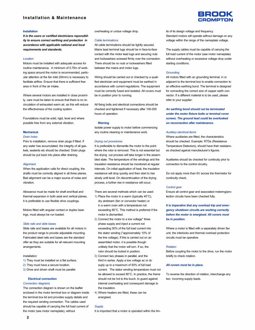
Installation & Maintenance
Installation
It is the users or certified electricians reponsibil-
ity to ensure correct earthing and protection in
accordance with applicable national and local
requirements and standards.
Location
Motors must be installed with adequate access for
routine maintenance. A minimum of 0.75m of work-
ing space around the motor is recommended, partic-
ular attention at the fan inlet (50mm) is necessary to
facilitate airflow. Ensure that there is sufficient free
area in front of the air intake.
Where several motors are installed in close proximi-
ty, care must be taken to ensure that there is no re-
circulation of exhausted warm air, as this will reduce
the effectiveness of the cooling system.
Foundations must be solid, rigid, level and where
possible free from any external vibration.
Mechanical
Drain holes
Prior to installation, remove drain plugs if fitted. If
any water has accumulated, the integrity of all gas-
kets, sealants etc should be checked. Drain plugs
should be put back into place after draining.
Alignment
When the application calls for direct coupling, the
shafts must be correctly aligned in all three planes.
Bad alignment can be a major source of noise and
vibration.
Allowance must be made for shaft end-float and
thermal expansion in both axial and vertical planes.
It is preferable to use flexible drive couplings.
Motors fitted with angular contact or duplex bear-
ings, must always be run loaded.
Slide rails and slide bases
Slide rails and bases are available for all motors in
the product range to provide adjustable mounting.
Fabricated steel rails and bases are the standard
offer as they are suitable for all relevant mounting
arrangements.
Installation:
1) They must be installed on a flat surface.
2) They must have a secure location.
3) Drive and driven shaft must be parallel.
Electrical connection
Connection diagrams
The connection diagram is shown on the leaflet
enclosed in the motor terminal box or diagram inside
the terminal box lid and provides supply details and
the required winding connection. The cables used
should be capable of carrying the full load current of
the motor (see motor nameplate), without
overheating or undue voltage drop.
Cable terminations
All cable terminations should be tightly secured.
Mains lead terminal lugs should be in face-to-face
contact with the motor lead lugs and securing nuts
and lockwashers screwed firmly over the connection.
There should be no nuts or lockwashers fitted
between the mains and motor lugs.
Wiring should be carried out or checked by a quali-
fied electrician and equipment must be earthed in
accordance with current regulations. The equipment
must be correctly fused and isolated. All covers must
be in position prior to running.
All fixing bolts and electrical connections should be
checked and tightened if necessary after 100-200
hours of operation.
Warning
Isolate power supply to motor before commencing
any routine cleaning or maintenance work.
Drying out procedures
It is preferable to dismantle the motor to the point
where the rotor is removed. This is not essential but
the drying out process will take longer in the assem-
bled state. The temperature of the windings and the
insulation resistance should be monitored at regular
intervals. On initial application of heat, the insulation
resistance will drop quickly and then start to rise
slowly until level. On discontinuation of the drying
process, a further rise in resistance will occur.
There are several methods which can be used:
1) Place the motor in a warm (typically 40°C),
dry airstream (fan or convector heater) or
in a warm oven with a temperature not
exceeding 80°C. This method is preferred if the
motor is dismantled.
2) Connect the motor to a low voltage* three
phase supply and inject a current not
exceeding 50% of the full load current into
the stator winding (*approximately 10% of
the line voltage). If this is carried out on an
assembled motor, it is possible though
unlikely that the motor will turn. If so, the
rotor should be locked in position.
3) Connect two phases in parallel, and the
third in series. Apply a low voltage ac or dc
suply up to a maximum of 50% of full load
current. The stator winding temperature must not
be allowed to exceed 80°C. In practice, the frame
should not be hot to the touch, to guard against
internal overheating and consequent damage to
the insulation.
4) Where heaters are fitted, these can be
energised.
Supply
It is important that a motor is operated within the lim-
its of its design voltage and frequency.
Standard motors will operate without damage on any
voltage within the range of the nameplate voltage.
The supply cables must be capable of carrying the
full load current of the motor (see motor nameplate)
without overheating or excessive voltage drop under
starting conditions.
Grounding
All motors fitted with an grounding terminal, in or
adjacent to the terminal box to enable connection to
an effective earthing bond. The terminal is designed
for connecting the correct size of copper earth con-
nector. If a different material is to be used, please
refer to your supplier.
An earthing bond should not be terminated
under the motor fixture bolts or terminal cover
screws. The ground lead could be overlooked
on reconnection after maintenance.
Auxiliary electrical items
Where auxiliaries are fitted, the characteristics
should be checked. Example: RTDs (Resistance
Temperature Detectors), should have their resistanc-
es checked against manufacturer’s figures.
Auxiliaries should be checked for continuity prior to
connection to the control circuitry.
Do not apply more than 6V across the thermistor for
continuity check.
Control gear
Ensure all control gear and associated metering/pro-
tection circuits have been checked fully.
It is imperative that any overload trip and emer-
gency shutdown circuits are working correctly
before the motor is energised. All covers must
be in position.
Where a motor is fitted with a separately driven fan
unit, the interlocks and thermal overload protection
circuits must be operative.
Rotation
Before coupling the motor to the drive, run the motor
briefly to check rotation.
All covers must be in place.
To reverse the direction of rotation, interchange any
two incoming supply leads.
2

Installation & Maintenance
Starting
Motors are rated by the output required, the number
of starts per hour, the load curve/inertia and environ-
mental considerations.
Operating outside the contractual parameters may
thermally overload the motor, eg too many starts per
hour, or mechanically stress components, eg over-
speeding.
Refer to starter literature for methods of start
and safety precautions to be taken.
Running
After one hour of running, check the general vibra-
tion levels. If these are excessive, check alignment
(and belt tensioning if belt driven).
Some initial bearing noise may be present during the
running-in period. This is normal because the grease
has to settle down within the bearing. This noise
should disappear after a few hours of operation.
Check that the motor runs up smoothly and within
the permitted run-up time. Note that repeated start-
ing in quick succession may lead to a thermal over-
load of the motor.
Fitting couplings and alignment
Extreme care must be exercised in lining up cou-
plings as misalignment can be detrimental to the
shaft and bearings. For direct drives, we recommend
that flexible couplings are used. Please ensure that
the alignment instructions given by the coupling
manufacturer are followed.
Do not at any time force in the fitting of couplings,
pulleys etc. All motors are provided with a threaded
hole in the drive end shaft to assist fitting and
removal. A bolt should be used in this hole and a nut
with a large washer used to press the coupling or
pulley against the shoulder of the shaft. Care must
also be taken to ensure that the motor bearings are
not subjected to end-thrust caused by the two halves
of the couplings being squeezed too tightly together.
Please ensure that all couplings, belts, pulleys etc
are properly and permanently guarded against acci-
dental contact while the motor is running.
Care should be taken to ensure fixing bolts are cor-
rectly tightened.
Belts drives
Please ensure that the V-belts are of the same man-
ufacture and have the same dimensions. Also
ensure that the belts are correctly tensioned in
accordance with the manufacturer’s recommenda-
tions. If the V-belts are not tensioned correctly, it can
cause belt and pulley wear and/or shaft and bearing
damage. When replacing belts, it is recommended
that all belts be replaced at the same time. It is also
not generally recommended to use two pole motors
for belt drive applications.
Motor modifications
Warning
All modifications should be carried out by a trained
operative. Do not work under suspended load and
use correct lifting equipment.
Changing terminal box position
(on multi-mount motors)
1) Lift motor, using eyebolt or lifting lugs
provided
2) Slacken / remove the foot fixing bolts
on one foot
3) Pull the foot away from the frame
4) Repeat stages 2 to 3 on the other foot
5) Lower the motor onto two pieces of
timber
6) Remove the eyebolt or lifting lugs
7) Rotate the motor until the terminal box is
in the correct position.
8) Refit the eyebolt or lifting lugs on the
machined pads at the top of the motor
(diagonally opposite corners for lifting
lugs). Ensure that lifting lugs are in
contact with all machined faces and that
the correct bolts and nuts are used.
Tighten the bolts to the correct torque.
9) Remove fan cover
10) Remove the endshield bolts at both ends
of the motor.
11) Slacken drive end bearing cap or
clamping screws to allow endshield
spigot to disengage.
12) If grease nipples are fitted, disengage
both endshield spigots and rotate the
endshields through 90° until the grease
nipples are at the top, or the desired
position.
13) Refit endshield bolts and tighten to the
correct torque.
14) Retighten the bearing cap screws at the
drive end, replacing the washers
under the bolt heads. Tighten screws to
the correct torque.
15) Lift motor using the eyebolt hooks or the
lifting lugs.
16) Strip paint from the pads where the feet
are to be fitted and apply a thin film of
grease for corrosion protection on bare
surfaces.
17) Refit the feet in the reverse order of
dismantling (steps 2 and 3).
18) Ensure the feet are fully in contact with
the machined faces. Tighten all bolts to
the correct torque.
19) Repeat stages 18 to 19 on the other foot.
20) Prime and paint all machined surfaces
left exposed by the changes.
21) Refit fan cover with the greasing hole in
the correct position (if in doubt, contact
your supplier).
Note:
If drain holes were present they may now be
positioned at the top of the motor.
Bearings, grease, bearing change
Grease
Regreasable bearings are pre-packed with a lithium
or lithium complex based grease.
Other lithium based greases of a similar consistency
would be compatible. See table below for some
alternatives:
Where a special grease has been supplied, this will
be indicated on the motor nameplate.
Regreasing
Standard regreasing facilities, where provided, are
situated on the periphery of the drive end and non-
drive endshields.
Grease relief is via a:
a) Diaphragm relief valve.
b) Rotating grease relief flinger.
c) Plugged grease chute.
For motors with open bearings and without grease
relief facilities, the old grease must be cleaned out
from time to time by removing the bearing cap
and/or endshield. The bearing and housing must
then be re-packed with grease and reassembled. Do
not overfill the bearing housing - it should not be
more than a quarter full of grease after reassembly.
Motors with sealed for life bearings usually employ a
polyurea EA6 grease. These should be fitted with
new bearings based on the bearing life stated in the
product catalogue.
An overgreased bearing will cause overheating of
the bearing with the possible escape of the grease,
loss of lubrication qualities, leading to ultimate bear-
ing failure.
Grease Reference Manufacturer
Alternative lithium complex greases
EnergreaseCastrolLuplexUnirexSovereignMobilgreaseLiplexHytexRetinaxLGHT3
LC2LMXM2
N2LSHP
EP2EP2LX-
BPCastrolCentury
EssoGulf
Mobil
ShellTexacoShellSKF
3

Installation & Maintenance
Lubrication procedure
The following procedure should be adopted:
1) Wipe clean the grease gun fitting and the
regions around the motor grease fittings.
2) Remove the grease relief plug if fitted.
Some motors will have one way grease
valves which should be left in place.
3) Add a small quantity of grease,
approximately 4 to 10 shots depending
on frame size.
4) Allow motor to run for approximately 10
minutes in order that excess grease may
be expelled before refitting the relief plug.
Bearings fitted with rotating grease relief
or through grease valves will relieve
automatically. Grease may not be
expelled from the motor during filling due to
internal cavities/pipes filling or relief via seals.
5) On initial start up or after relubrication,
‘bearing noise’ may result from the new
grease moving around the bearing. This
noise is normal and will disappear after a
few hours of running.
Bearing change
When fitting new bearings, the parts should be
lightly lubricated with grease.
The bearing should be driven onto the shaft by pres-
sure on the inner race only using a short length of
tube placed over the motor shaft.
On larger motors, it is easier to raise the tempera-
ture of the bearing using an oil bath, oven or induc-
tion heating. The temperature must be controlled to
120°C maximum. Suitable handling precautions
should be taken.
The bearing should then be quickly slipped into
place, ensuring that the bearing is in contact with the
shaft shoulder.
When cool, ensure that the bearing is clean and
charge the bearing with the recommended quantity
of grease. Bearings and housings should be approx-
imately a quarter full.
Fitting flange adaptor (where applicable)
1) If required, remove foot as detailed in
terminal box position change.
2) If required, reposition terminal box and
lifting lugs.
3) Clean paint off the drive end endshield
spigot and remove all the plastic bolt-hole
cover caps. Apply a film of non-setting
jointing compound on bare machined
surfaces for sealing and corrosion
protection.
4) Fit flange ring onto spigot positioning fixing holes,
where applicable, to provide either BS or DIN
flange hole positions.
5) Bolt ring into position, using the same
size socket head bolts as used on the feet.
These are supplied with the flange ring kit.
6) Tighten the bolts to correct torque.
Change from ball/ball to roller/ball construction
200 - 355 ~ 324T - 586 frame
1) Isolate motor before commencing work.
2) Remove fan cover and fan.
3) Remove bearing cap screws.
4) Remove endshield at both ends.
5) Remove bearing circlips at both ends.
6) Remove preload washer at non-drive end.
7) Replace drive end ball bearing with new
roller bearing and refit circlip.
8) Remove non-drive end ball bearing and
inner bearing cap.
9) Fit new non-drive end inner bearing cap
with shallow recess (identical to existing
drive end inner bearing cap.
10) Examine existing non-drive end ball
bearing and either refit or replace.
11) Refit non-drive end bearing circlip.
12) Re-pack bearings with new grease in
accordance with recommendations.
13) Ensure the lip on both oilseals is
greased.
14) Refit both endshields and check that:
a) spacer O/D is the same
as the bearing O/D
b) bearing spacer supplied is fitted into
the non-drive end and endshield
bearing recess
c) slots in inner bearing caps are
aligned with endshield grease chutes
d) correct location for bearing cap by
the use of a stud
e) bolts are torqued up to
recommended figures
Maintenance
Ongoing maintenance
Induction motors by their very nature require very lit-
tle maintenance. However a regular regime of
inspection is recommended to ensure minor prob-
lems do not escalate to breakdowns. Typical inter-
vals would be 2000 hours of operation or 3 months,
whichever is the sooner.
Checklist:
• No visible damage, ie fans cracked, fan
cowls bent, foot cracked etc
• No accumulation of dust or fibres on the
frame or around the fan inlet
• No significant corrosion of the lifting
lugs/eyebolts
• No excessive vibration
• No loose fasteners
• Cables and earth are sound
• Sealing of the motor and gland plate in
good condition
• Insulation resistance adequate, imperative this
is checked after a prolonged shut-down
• Regrease required, particularly large
output 2 pole motors
• Bearing condition
Note:
Smoke extraction motors or motors on safety
critical applications should be rewound, to the
original specification, after 40,000 hours of oper-
ation. If variable speed employing unipolar
switching the period is reduced to 30,000 hours
and reduced again to 20,000 hours for bipolar
switching. In all cases refer to your supplier.
Periodic maintenance
Remove the fan cover and the fan which is keyed,
clamped, pinned or knurl located to the shaft exten-
sion. Loosen and remove bearing cover screws and
endshield bolts/studs. The endshields should then
be eased off their spigots.
The rotor can now be carefully withdrawn from the
stator, taking care not to damage the stator bore
and both stator and rotor windings.
Having dismantled the motor, maintenance can be
carried out to remove all dirt. For this purpose, the
use of an air line supplying dry compressed air
under comparatively low pressure is best, as a high
velocity airstream can force dirt into the spaces
between the windings and insulation etc. Grease-
removing solvents should only be used very sparing-
ly to avoid damage to impregnating varnish or insu-
lation.
Motors should be re-assembled in the reverse order
from dismantling, remembering to ease endshields
onto bearings and spigots. Do not use force. On re-
assembly oilseals to mating faces should be lubricat-
ed. If oilseals are worn or damaged during disman-
tling then they should be replaced before continuing.
Before starting the motor, check that the rotor
revolves freely. Ensure that the electrical connec-
tions are correct and terminal nuts tight (see section
- Electrical Connection).
Spares and repairs
When ordering spares, it is important to state the
motor serial number to ensure that the correct
spares will be supplied.
Metric NEMARegreasing
facility
Standard regreasing facilities
63-180*
200-355
56-286
324-587
on request
standard
Type
* Bearings are double shielded and pre-packed with grease for life
4

Installation & Maintenance
Notes
Fixing bolts, nuts, studs, screws, spacers or washers
are not included with these parts and, if required,
should be clearly specified on the order in addition to
the part description number. The fixing duty and part
description reference number for which they are
required, should also be clearly stated.
Contact must be made prior to any remedial action
being taken under warrantee
Please quote the motor serial number in all such
cases with full details of the problem.
Exploded view of a typical standard ac motor
12
3
45
6
78
9
1011
12
1314
15
Ref Part description
Flange endshieldEndshield fixing bolt
Drive end endshield
Rotor assemblyFlinger (when fitted)
Drive end oil seal (when fitted)
Preload washerDrive end bearing
Stator assembly with or without feet
Eyebolt (when fitted) or dual lifting lugBearing retention circlip
Non-drive end bearing
Non-drive end endshieldEndshield fixing bolt
Bearing circlip
16
1718
19
2021
22
2324
25
2627
28
2930
Ref Part description
Non-drive end oilseal (when fitted)
FanFan circlip
Fan cover
Fan cover screw and washerFoot fixing bolts and washer (where applicable)
Feet
Terminal board (when fitted)Terminal box to frame gasket
Terminal box
Internal earth terminalTerminal box lid gasket
Terminal box lid
Pad mounting bracketFace endshield
5

Bearing Information
63
7180M
90S/L
100L
112M
132S/M
160M/L180M/L
200LX
225S
225M
250ME
280SE
280ME
315SE
315ME
315M
315L
355S/M/L
Bearing references and oil seals for horizontally-mounted motors only
European
63
7180M
90S/L
100L
112M
132S/M
160M/L180M/L
200LX
225S
225M
250S
250M
280S
280M
315S
315M
315L
355S/M/L
BS
All
All
All
All
All
All
All
All
All
All
All
All
2
4 up
2
4 up
2
4 up
2
4 up
2
4 up
2
4 up
2
4 up
2
4 up
Polarity
Bearings(1)
Drive end Non-drive end
Oil seals(2)
62022Z
60032Z
62042Z
62052Z
62062Z
62062Z
62082Z
63092Z
63102Z
6312
6313
6314
6314
6316
6314
6318
6314
6318
6316
6319
6316
6319
6316
6319
6316
6319
N316
N324
62022Z
60032Z
60032Z
62032Z
62052Z
62052Z
63052Z
63072Z
63082Z
6312
6313
6314
6314
6316
6314
6318
6314
6318
6316
6319
6316
6319
6316
6319
6316
6319
6316
6324
15 x 24 x 5(3)
17 x 28 x 6(3)
20 x 30 x 7(3)
25 x 35 x 7(3)
30 x 42 x 7(3)
30 x 42 x 7(3)
40 x 52 x 7(3)
45 x 60 x 8(3)
50 x 65 x 8(3)
60 x 80 x 8(3)
65 x 90 x 10(4)
70 x 90 x 10(4)
70 x 90 x 10(4)
80 x 110 x 10(3)
70 x 90 x 10(4)
90 x 120 x 12(3)
70 x 90 x 10(4)
90 x 120 x 12(3)
70 x 90 x 10(4)
90 x 120 x 12(3)
70 x 90 x 10(4)
90 x 120 x 12(3)
70 x 90 x 10(4)
90 x 120 x 12(3)
70 x 90 x 10(4)
90 x 120 x 12(3)
75 x 100 x 10(4)
115 x 145 x 14(3)
Drive end
15 x 24 x 5(3)
17 x 28 x 6(3)
15 x 24 x 5(3)
17 x 28 x 6(3)
25 x 37 x 7(3)
25 x 37 x 7(3)
25 x 37 x 7(3)
35 x 47 x 7(3)
40 x 52 x 7(3)
60 x 80 x 8(3)
65 x 90 x 10(4)
70 x 90 x 10(4)
70 x 90 x 10(4)
80 x 110 x 10(3)
70 x 90 x 10(4)
90 x 120 x 12(3)
70 x 90 x 10(4)
90 x 120 x 12(3)
70 x 90 x 10(4)
90 x 120 x 12(3)
70 x 90 x 10(4)
90 x 120 x 12(3)
70 x 90 x 10(4)
90 x 120 x 12(3)
70 x 90 x 10(4)
90 x 120 x 12(3)
75 x 100 x 10(4)
115 x 145 x 14(3)
Non-drive end
(1) Frame sizes 80 and 90 have bearings with CN clearances, frame sizes 100 to 355 have bearings with C3 clearance ‘medium’ series(2) Sizes given are in mm, and represent bore x outside diameter x widthMaterial: (3) Nitrile rubber (4) Silicon rubber
IEC Type
Bearing references and oil seals for horizontally-mounted motors only
56143/5T
182/4T213/5T
254/6T
284/6T
324T326T
364T
365T
404/5T
444/7T
504/5
Frame
All
All
All
All
All
All
All
All
All
2
4 up
2
4 up
2
4 up
2
4 up
Polarity
Bearings(1)
Non-drive end
Oil seals(2)
62042Z
62052Z
62062Z
62082Z
63092Z
63102Z
6312
6313
6314
6314
6316
6314
6318
6316
6319
6316
6319
60032Z
62032Z
62052Z
63052Z
63072Z
63082Z
6312
6313
6314
6314
6316
6314
6318
6316
6319
6316
6319
15 x 24 x 5(3)
17 x 28 x 6(3)
30 x 42 x 7(3)
40 x 52 x 7(3)
45 x 60 x 8(3)
50 x 65 x 8(3)
60 x 80 x 8(3)
65 x 90 x 10(4)
70 x 90 x 10(4)
70 x 90 x 10(4)
70 x 90 x 10(4)
70 x 90 x 10(4)
90 x 120 x 12(3)
70 x 90 x 10(4)
90 x 120 x 12(3)
90 x 120 x 12(3)
90 x 120 x 12(3)
Drive end
15 x 24 x 5(3)
17 x 28 x 6(3)
25 x 37 x 7(3)
25 x 37 x 7(3)
35 x 47 x 7(3)
40 x 52 x 7(3)
60 x 80 x 8(3)
65 x 90 x 10(4)
70 x 90 x 10(4)
70 x 90 x 10(4)
70 x 90 x 10(4)
70 x 90 x 10(4)
90 x 120 x 12(3)
70 x 90 x 10(4)
90 x 120 x 12(3)
90 x 120 x 12(3)
90 x 120 x 12(3)
Non-drive end
(1) Frame sizes 56 to143/5T have bearings with CN clearances, frame sizes 182T to 505 have bearings with C3 clearance ‘medium’ series
(2) Sizes given are in mm, and represent bore x outside diameter x widthMaterial: (3) Nitrile rubber (4) Silicon rubber
NEMA Type
Drive end
6

Connection Diagrams - IEC Frames
7

Connect ion Diagrams - NEMA
8

Fault Finding - Three Phase Induction Motors
Motor will not start
Supply or starter trips out atstart
Motor starts but has no torque.Motor does not reach full speedor takes a long time to accelerate
Motor overheating
No load amps in excess of fullload amps.
1. Fault with supply.
2. Motor or load locked up.
3. Wrong connection in controlcircuit.
1. Wrong or loose connections.
2. Motor overloaded.
3. Inertia of load too high.
4. Low voltage due to volt dropin cables.
5. Overload or circuit breakerincorrectly set or sized.
1. Incorrect connection.
2. Delta wound motor connected in star.
3. Star/Delta starter staying instar.
4. Inertia of load too high.
5. Motor overloaded.
6. Low voltage due to drop incables.
1. Motor overloaded.
2. Ineffective cooling.Temperature of air.Look for build up of dirt
3. Excessiive ambient.
4. Wrong connections.
5. Delta wound motor in star.
6. Motor ‘Single Phasing”.
7. Wrong voltage or frequency.
8. Supply voltage unbalanced.
1. Incorrect connection.
2. Star wound motor connected Delta.
3. Voltage in excess of nameplate.
4. Motor supplied for a different voltage or frequency.
1. Check for correct voltage atmotor terminals.2. Make sure motor and loadare free to turn.3. Check to ensure contactorsoperate.
1. Check all lugs are properlycrimped or soldered, and connections are tight.2. Check load performancedata against motor performance data.3. Measure voltage at motorterminals while motor starting.4. Check settings of overloadand circuit breaker and allowfor starting current.
1. Check connection diagramand nameplate data.2. Check load performancedata against motor performance data.3. Measure voltage at motorterminals while motor starting.
1. Check load performancedata.2. Check fan and air flow.
3. Check connection diagramand nameplate data.4. Check volts and amps on allthree phases.5. Check nameplate
6. Check phase to phase voltage accurately.
1&2. Check connection diagram
3. Measure voltage at motorterminals.
4. Compare supply voltage andfrequency to nameplate.
1.. Fit new fuses, reset circuitbreakers, etc.2. Remove clamps, locks etc.
3. Sort out control circuit.
1. Fix up connections.
2. Change motor for correctsize.
3. Change cables for correctsize.4. Correct setting of overloador breaker or change.
1. Sort out and correct connections.2. Check timer and startercontrol circuit.
3. Change motor for correctsize.
4. Change cables for correctsize.
1. Fix problem with load or fit alarger motor.2. Clean motor. Sort out cool-ing of air temp. and flow.
3. Sort out connections.
4. Restore supply to all phases
5. Correct voltage or frequency
6. Balance supply or acceptunbalance
1&2. Sort out and correct connections at motor terminals.
3. Connect supply voltage.
4. Change motor for correctvoltage and frequency.
9

Fault Finding - Three Phase Induction Motors
Mechanical noise or vibration.Noisy bearings. Bearingsoverheating
Motor amps in excess of nameplate full load amps onload.
Excessive electrical noise
Unbalanced amps in differentphases when motor loaded
Motor runs in wrong direction
1. Thrust from load ormisalignment..
2. Damaged bearings, toomuch grease, no grease, or foreign matter in grease.
3. Rotor pulling or foreign matter in air gap.
4. Out of balance load, coupling or pulley.
5. Excessive belt pull.
6. Motor foundations not ridgid
1. Motor overloaded
2. Low voltage supply
3. Wrong voltage and frequency.
4. Wrong connections.
5. Motor “Single Phasing”.
6. Supply voltage unbalanced
7. Motor speed not matched toload.1. Wrong connections
2. Wrong voltage.
3. Motor “Single Phasing”
1. Unbalanced power supply.
1. Wrong connections.
1. Check gaps between cou-pling halves and alignment.
2&3. Turn shaft slowly by handand feel for roughness or stiffness. Check for bent shaftor fan rubbing.
4. Run motor disconnectedfrom load and then with pulleyor coupling removed.5. Run motor without belts.
6. Check design and construction foundations.performance data.
1. Check load and performance data.2. Measure voltage at motorterminals.3. Check nameplate data.
4. Check nameplate data..
5&6 Check volts and amps inall three phases.
7. Measure motor speed andcheck load requirements.1. Check connections.
2. Check voltage with nameplate.3. Check volts and amps on allthree phases.1. Measure phase to phase voltage accurately.
1. Watch shaft rotation.
1. Re-align couplings.
2&3. Clean bearing housing,change bearings and repackwith fresh grease.
4. Fix up out of balance items.
5. Loosen belt tension.
6. Increase strength of foundations.
1. Fix problem with load or fitlarger motor.2. Fix problem, maybe withlarger cables.3. Correct voltage or frequency
4. Sort out and correct.
5&6 Resore balanced supplyto all three phases.
7. Change motor for correctmotor speed.1. Fix connections.
2. Correct voltage.
3. Restore supply to all phases
1. Balance supply or acceptunbalance
1. Swap any two phases ofsupply.
10

Brook Crompton264 Attwell DriveToronto, Ontario M9W 5B2Tel: 416 675-3844Fax: 416 675-6885Internet: www.brookcromptonna.com
Printed in Canada15/09/04 - 2004.W.OI Issue 1
© Copyright 2002. Brook Crompton. All rights reserved
CALL TOLL FREE - NORTH AMERICA:
1-800-463-89171-800-463-8917OROR
1-800-668-67791-800-668-6779FAX:
416-675-6885847-253-9880
www.brookcromptonna.com
Customer Service
Quebec only:1-888-668-9843
Fax:514-636-4253
Every care has been taken to ensure the accuracy
of the information contained in this publication, but,
due to a policy of continuous development and
improvement the right is reserved to supply
products which may differ slightly from those
illustrated and described in this publication

Issue Date : 2011-09-30 Z - Variable Frequency Drives
Variable Frequency Drives
As variable frequency drives (VFDs) from multiple manufacturers are used in Seresco Technologies Inc.'s
products, please ensure that you are aware which model is used in your unit before consulting this guide.
Siemens MicroMaster VFDs
WARNING This equipment contains dangerous voltages and controls potentially dangerous
rotating mechanical parts. Non-compliance with Warnings failure to follow the instructions contained in
this manual can result in loss of life, severe personal injury or serious damage to property. Only suitable
qualified personnel should work on this equipment, and only after becoming familiar with all safety
notices, installation, operation and maintenance procedures contained in this manual. The successful and
safe operation of this equipment is dependent upon its proper handling, installation, operation and
maintenance.
WARNING The DC link of all MICROMASTER modules remains at a hazardous voltage level
for 5 minutes after all voltages have been disconnected. Therefore always wait for 5 minutes after
disconnecting the inverter from the power supply before carrying out work on any modules. The drive unit
discharges itself during this time.
This equipment is capable of providing internal motor overload protection in accordance with UL508C section
42. Refer to P0610 (level 3) and P0335. Motor overload protection can also be provided using an external PTC
via a digital input. This equipment is suitable for use in a circuit capable of delivering not more than 10,000
symmetrical amperes (rms), for a maximum voltage of 230/460 V when protected by an H or K type fuse, a
circuit breaker or self-protected combination motor controller controller (for more details see Operating
Instructions Appendix F). Use Class 1 60/75 °C copper wire only with the cross-sections as specified in the
Operating Instructions.
Before installing and commissioning, please read these safety instructions and warnings carefully and all the
warning labels attached to the equipment. Make sure that the warning labels are kept in a legible condition and
replace missing or damaged labels.
Table 1. Maximum permissible ambient temperature
Frame Sizes A-F50 °C at constant torque (CT) and 100 %
40 °C at variable torque (VT) and 100 %
1

Z - Variable Frequency Drives Issue Date : 2011-09-20
Frame Sizes FX and GX 40 °C at 100 % permissible output current
MM420 MM440
Figure 1. MM420 Block Diagram Figure 2. MM440 Block Diagram
Figure 3. MM420 LED Status Display Figure 4. MM440 LED Status Display
2

Issue Date : 2011-09-30 Z - Variable Frequency Drives
Table 2. Fault Messages
MM420 MM440
Fault Significance Fault Significance
F0001 Overcurrent
F0002 Overvoltage F0002 Overvoltage
F0003 Undervoltage F0003 Undervoltage
F0004 Inverter Overtemperature F0004 Inverter Overtemperature
F0005 Inverter I2t F0005 Inverter I2t
F0011 Motor Overtemperature I2t F0011 Motor Overtemperature I2t
F0012 Inverter temp. Signal lost
F0015 Motor temp. Signal lost
F0010 Mains Phase Missing
F0021 Earth Fault
F0022 HW Monitoring Active
F0023 Output Fault
F0024 Rectifier Overtemperature
F0030 Fan Has Failed
F0035 Auto Restart after n
F0040 Automatic Calibration Failure
F0041 Stator resistance measurement failure F0041 Motor Data Identification Failure
F0042 Speed Control Optimization Failure
F0051 Parameter EEPROM Fault F0051 Parameter EEPROM Fault
F0052 Powerstack Fault F0052 Powerstack Fault
F0053 IO EEPROM Fault
F0054 Wrong IO Board
F0060 Asic Timeout F0060 Asic Timeout
F0070 Communications board setpoint error F0070 Communications board setpoint error
F0071 No Data for USS (RS232 link) during Telegram Off Time F0071 USS (BOP Link) setpoint fault
F0072 No Data from USS (RS485 link) during Telegram Off Time F0072 USS (COM Link) setpoint fault
F0080 Analogue input - lost input signal F0080 Analogue input - lost input signal
F0085 External Fault F0085 External Fault
F0090 Encoder Feedback Loss
F0101 Stack Overflow F0101 Stack Overflow
F0221 PI Feedback below minimum value F0221 PI Feedback below minimum value
F0222 PI Feedback above maximum value F0222 PI Feedback above maximum value
F0450 BIST Tests Failure F0450 BIST Tests Failure
F0452 Belt Failure Detected
3
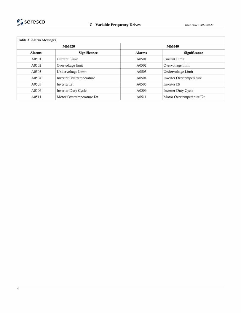
Z - Variable Frequency Drives Issue Date : 2011-09-20
Table 3. Alarm Messages
MM420 MM440
Alarms Significance Alarms Significance
A0501 Current Limit A0501 Current Limit
A0502 Overvoltage limit A0502 Overvoltage limit
A0503 Undervoltage Limit A0503 Undervoltage Limit
A0504 Inverter Overtemperature A0504 Inverter Overtemperature
A0505 Inverter I2t A0505 Inverter I2t
A0506 Inverter Duty Cycle A0506 Inverter Duty Cycle
A0511 Motor Overtemperature I2t A0511 Motor Overtemperature I2t
4

Issue Date : 2011-09-30 Z - Variable Frequency Drives
A0520 Rectifier Overtemperature
A0521 Ambient Overtemperature
A0522 I2C read out timeout
A0523 Output fault
A0535 Braking Resistor Output
A0541 Motor Data Identification Active A0541 Motor Data Identification Active
A0542 Speed Control Optimization Active
A0590 Encoder feedback loss warning
A0600 RTOS Overrun Warning A0600 RTOS Overrun Warning
A0700 - AO709 CB warning A0700 - AO709 CB warning
A0710 CB communication error A0710 CB communication error
A0711 CB configuration error A0711 CB configuration error
A0910 Vdc-max controller de-activated A0910 Vdc-max controller de-activated
A0911 Vdc-max controller active A0911 Vdc-max controller active
A0912 Vdc-min controller active
A0920 ADC parameters not set properly A0920 ADC parameters not set properly
A0921 DAC parameters not set properly A0921 DAC parameters not set properly
A0922 No load applied to inverter A0922 No load applied to inverter
A0923 Both JOG Left and JOG Right are
requested
A0923 Both JOG Left and JOG Right are
requested
A0952 Belt Failure Detected
A0936 PID Autotuning Active
5

Z - Variable Frequency Drives Issue Date : 2011-09-20
ABB VFDs
ACS 350
WARNING Ignoring the following instructions can cause physical injury or death, or damage to
the equipment. Only qualified electricians are allowed to install and maintain the drive! Never work on the
drive, motor cable or motor when input power is applied. After disconnecting the input power, always wait
for 5 minutes to let the intermediate circuit capacitors discharge before you start working on the drive,
motor or motor cable.
Before performing any maintenance activity, ensure by measuring with a multimeter (impedance at least 1
Mohm) that:
1. There is no voltage between the drive input phases U1, V1 and W1 and the ground.
2. There is no voltage between terminals BRK+ and BRK- and the ground.
Do not work on the control cables when power is applied to the drive or to the external control circuits.
Externally supplied control circuits may carry dangerous voltage even when the input power of the drive is
switched off.
Do not make any insulation or voltage withstand tests on the drive.
If a drive whose EMC filter is not disconnected is installed on an IT system [an ungrounded power system
or a high resistance-grounded (over 30 ohms) power system], the system will be connected to earth potential
through the EMC filter capacitors of the drive. This may cause danger or damage the drive.
If a drive whose EMC filter is not disconnected is installed on a corner grounded TN system, the drive will
be damaged.
WARNING Even when the motor is stopped, dangerous voltage is present at the power circuit
terminals U1, V1, W1 and U2, V2, W2 and BRK+ and BRK-
WARNING The drive is not field repairable. Never attempt to repair a malfunctioning drive;
contact your local ABB representative or Authorized Service Center for replacement. Make sure that dust
from drilling does not enter the drive during the installation. Electrically conductive dust inside the drive
may cause damage or lead to malfunction. Ensure sufficient cooling.
6

Issue Date : 2011-09-30 Z - Variable Frequency Drives
Operation and Start-up
Do not activate automatic fault reset functions if dangerous situations can occur. When activated, these
functions will reset the drive and resume operation after a fault.
Do not control the motor with an AC contactor or disconnecting device (disconnecting means); use instead
the control panel start and stop keys or external commands (I/O or fieldbus). The maximum allowed
number of charging cycles of the DC capacitors (i.e. power-ups by applying power) is two per minute and
the maximum total number of chargings is 15 000.
If an external source for start command is selected and it is ON, the drive will start immediately after an
input voltage break or fault reset unless the drive is configured for 3 wire (a pulse) start/stop.
When the control location is not set to local (LOC not shown on the display), the stop key on the control
panel will not stop the drive. To stop the drive using the control panel, press the LOC/REM key LOC and
then the stop key.
Figure 5. ACS 350 Block Diagram
7

Z - Variable Frequency Drives Issue Date : 2011-09-20
Table 4. Alarm and Fault Codes
8

Issue Date : 2011-09-30 Z - Variable Frequency Drives
9

Z - Variable Frequency Drives Issue Date : 2011-09-20
10

Issue Date : 2011-09-30 Z - Variable Frequency Drives
11

Z - Variable Frequency Drives Issue Date : 2011-09-20
12

Issue Date : 2011-09-30 Z - Variable Frequency Drives
13

Z - Variable Frequency Drives Issue Date : 2011-09-20
14
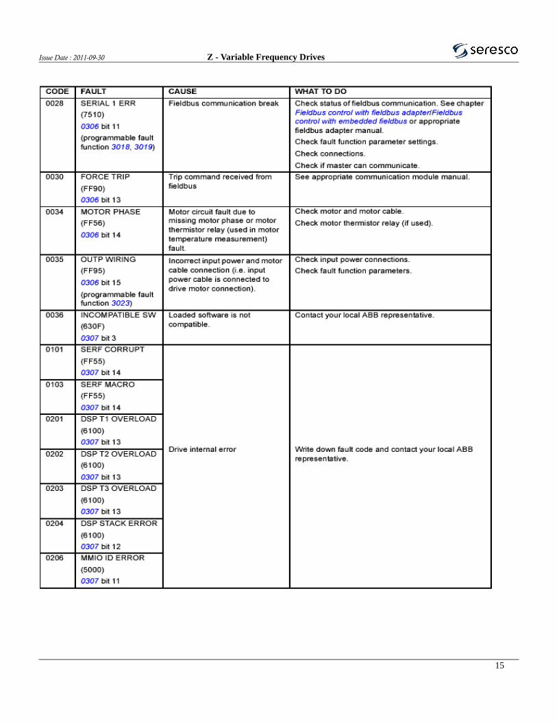
Issue Date : 2011-09-30 Z - Variable Frequency Drives
15

Z - Variable Frequency Drives Issue Date : 2011-09-20
16

Issue Date : 2011-09-30 Z - Variable Frequency Drives
ACH 550
WARNING The ACH550 adjustable speed AC drive should ONLY be installed by a qualified
electrician.
WARNING Even when the motor is stopped, dangerous voltage is present at the power circuit
terminals U1, V1, W1 (L1, L2, L3) and U2, V2, W2 (T1, T2 T3) and, depending on the frame size, UDC+
and UDC-, or BRK+ and BRK-
WARNING Dangerous voltage is present when input power is connected. After disconnecting the
supply, wait at least 5 minutes (to let the intermediate circuit capacitors discharge) before removing the
cover. Even when power is switched off from the input terminals of the ACH550, there may be dangerous
voltage (from external sources) on the terminals of the relay outputs.
WARNING When the control terminals of two or more drives are connected in parallel, the
auxiliary voltage for these control connections must be taken from a single source which can either be one
of the drives or an external supply. 1-4 ACH550-UH User’s Manual Safety
WARNING Disconnect the internal EMC filter when installing the drive on an IT system (an
ungrounded power system or a high-resistance-grounded [over 30 ohm] power system).
WARNING Do not attempt to install or remove EM1, EM3, F1 or F2 screws while
power is applied to the drive’s input terminals.
WARNING Do not control the motor with the disconnecting device (disconnecting means);
instead, use the control panel keys or commands via the I/O board of the drive. The maximum allowed
number of charging cycles of the DC capacitors (i.e. power-ups by applying power) is five in ten minutes.
WARNING Never attempt to repair a malfunctioning ACH550; contact the factory or your local
Authorized Service Center for repair or replacement.
17

Z - Variable Frequency Drives Issue Date : 2011-09-20
WARNING The ACH550 will start up automatically after an input voltage interruption if the
external run command is on.
Figure 6. Wiring Diagram ACH 550
18

Issue Date : 2011-09-30 Z - Variable Frequency Drives
Figure 7. Wiring Diagram ACH 550
19

ECblueBasic Version
EC-fanswith highest efciency
Assembly instructions
Software version: D1583...87A, D1680A from Version 1.00
L-BAL-F036-GB 1007 Index 004 Part.-No. 00295296-GB
english
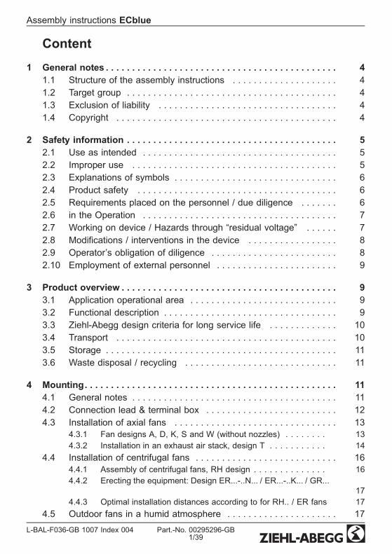
Content
1 General notes . . . . . . . . . . . . . . . . . . . . . . . . . . . . . . . . . . . . . . . . . . . . 41.1 Structure of the assembly instructions . . . . . . . . . . . . . . . . . . . . 41.2 Target group . . . . . . . . . . . . . . . . . . . . . . . . . . . . . . . . . . . . . . . . 41.3 Exclusion of liability . . . . . . . . . . . . . . . . . . . . . . . . . . . . . . . . . . 41.4 Copyright . . . . . . . . . . . . . . . . . . . . . . . . . . . . . . . . . . . . . . . . . . 4
2 Safety information . . . . . . . . . . . . . . . . . . . . . . . . . . . . . . . . . . . . . . . . 52.1 Use as intended . . . . . . . . . . . . . . . . . . . . . . . . . . . . . . . . . . . . . 52.2 Improper use . . . . . . . . . . . . . . . . . . . . . . . . . . . . . . . . . . . . . . . 52.3 Explanations of symbols . . . . . . . . . . . . . . . . . . . . . . . . . . . . . . . 62.4 Product safety . . . . . . . . . . . . . . . . . . . . . . . . . . . . . . . . . . . . . . 62.5 Requirements placed on the personnel / due diligence . . . . . . . 62.6 in the Operation . . . . . . . . . . . . . . . . . . . . . . . . . . . . . . . . . . . . . 72.7 Working on device / Hazards through “residual voltage” . . . . . . 72.8 Modications / interventions in the device . . . . . . . . . . . . . . . . . 82.9 Operator’s obligation of diligence . . . . . . . . . . . . . . . . . . . . . . . . 82.10 Employment of external personnel . . . . . . . . . . . . . . . . . . . . . . . 9
3 Product overview . . . . . . . . . . . . . . . . . . . . . . . . . . . . . . . . . . . . . . . . . 93.1 Application operational area . . . . . . . . . . . . . . . . . . . . . . . . . . . . 93.2 Functional description . . . . . . . . . . . . . . . . . . . . . . . . . . . . . . . . . 93.3 Ziehl-Abegg design criteria for long service life . . . . . . . . . . . . . 103.4 Transport . . . . . . . . . . . . . . . . . . . . . . . . . . . . . . . . . . . . . . . . . . 103.5 Storage . . . . . . . . . . . . . . . . . . . . . . . . . . . . . . . . . . . . . . . . . . . . 113.6 Waste disposal / recycling . . . . . . . . . . . . . . . . . . . . . . . . . . . . . 11
4 Mounting. . . . . . . . . . . . . . . . . . . . . . . . . . . . . . . . . . . . . . . . . . . . . . . . 114.1 General notes . . . . . . . . . . . . . . . . . . . . . . . . . . . . . . . . . . . . . . . 114.2 Connection lead & terminal box . . . . . . . . . . . . . . . . . . . . . . . . . 124.3 Installation of axial fans . . . . . . . . . . . . . . . . . . . . . . . . . . . . . . . 13
4.3.1 Fan designs A, D, K, S and W (without nozzles) . . . . . . . . 134.3.2 Installation in an exhaust air stack, design T . . . . . . . . . . . 14
4.4 Installation of centrifugal fans . . . . . . . . . . . . . . . . . . . . . . . . . . . 164.4.1 Assembly of centrifugal fans, RH design . . . . . . . . . . . . . . 164.4.2 Erecting the equipment: Design ER...-..N... / ER...-..K... / GR...
174.4.3 Optimal installation distances according to for RH.. / ER fans 17
4.5 Outdoor fans in a humid atmosphere . . . . . . . . . . . . . . . . . . . . . 17
Assembly instructions ECblue
L-BAL-F036-GB 1007 Index 004 Part.-No. 00295296-GB1/39

4.6 Motorheating . . . . . . . . . . . . . . . . . . . . . . . . . . . . . . . . . . . . . . . 18
5 Electrical installation . . . . . . . . . . . . . . . . . . . . . . . . . . . . . . . . . . . . . . 185.1 Safety precautions . . . . . . . . . . . . . . . . . . . . . . . . . . . . . . . . . . . 185.2 Connection . . . . . . . . . . . . . . . . . . . . . . . . . . . . . . . . . . . . . . . . . 18
5.2.1 Motor size “B” . . . . . . . . . . . . . . . . . . . . . . . . . . . . . . . . 195.2.2 Motor size “D” and “G” . . . . . . . . . . . . . . . . . . . . . . . . . . 20
5.3 EMC-compatible installation of control lines . . . . . . . . . . . . . . . . 215.4 Mains connection . . . . . . . . . . . . . . . . . . . . . . . . . . . . . . . . . . . . 21
5.4.1 Line voltage for 1~ types . . . . . . . . . . . . . . . . . . . . . . . . . 215.4.2 Line voltage for 3~ types . . . . . . . . . . . . . . . . . . . . . . . . . 215.4.3 Required quality attributes for the mains voltage . . . . . . . . . 22
5.5 Residual-current-operated protective device . . . . . . . . . . . . . . . . 225.6 Motor protection . . . . . . . . . . . . . . . . . . . . . . . . . . . . . . . . . . . . . 235.7 Analog input (0...10 V) for setting fan speed . . . . . . . . . . . . . . . 235.8 Output voltage +10 V . . . . . . . . . . . . . . . . . . . . . . . . . . . . . . . . . 245.9 Voltage supply for external devices, only motor sizes “D”, “G”
(+24 V, GND) . . . . . . . . . . . . . . . . . . . . . . . . . . . . . . . . . . . . . . 245.10 Enable, device ON / OFF (Digital In 1 = D1) . . . . . . . . . . . . . . . 245.11 Relay outputs (K1) . . . . . . . . . . . . . . . . . . . . . . . . . . . . . . . . . . . 255.12 Tacho out . . . . . . . . . . . . . . . . . . . . . . . . . . . . . . . . . . . . . . . . . . 255.13 Output Status Out OC (motor size “B”) . . . . . . . . . . . . . . . . . . . . 255.14 Potential at control voltage connections . . . . . . . . . . . . . . . . . . . 255.15 Add-on modules . . . . . . . . . . . . . . . . . . . . . . . . . . . . . . . . . . . . . 25
6 Start-up . . . . . . . . . . . . . . . . . . . . . . . . . . . . . . . . . . . . . . . . . . . . . . . . 266.1 Prerequisites for commissioning . . . . . . . . . . . . . . . . . . . . . . . . . 26
7 Diagnostics / Faults . . . . . . . . . . . . . . . . . . . . . . . . . . . . . . . . . . . . . . . 277.1 Trouble shooting . . . . . . . . . . . . . . . . . . . . . . . . . . . . . . . . . . . . . 277.2 For motor size “D” and “G” Status LED with ash code . . . . . . . 29
8 Service work. . . . . . . . . . . . . . . . . . . . . . . . . . . . . . . . . . . . . . . . . . . . . 318.1 Repairs / maintenance . . . . . . . . . . . . . . . . . . . . . . . . . . . . . . . . 318.2 Cleaning . . . . . . . . . . . . . . . . . . . . . . . . . . . . . . . . . . . . . . . . . . . 32
9 Enclosure . . . . . . . . . . . . . . . . . . . . . . . . . . . . . . . . . . . . . . . . . . . . . . . 329.1 Technical data . . . . . . . . . . . . . . . . . . . . . . . . . . . . . . . . . . . . . . 329.2 Connection diagram . . . . . . . . . . . . . . . . . . . . . . . . . . . . . . . . . . 349.3 EC Declaration of Incorporation . . . . . . . . . . . . . . . . . . . . . . . . . 36
Assembly instructions ECblue
L-BAL-F036-GB 1007 Index 004 Part.-No. 00295296-GB2/39

9.4 Index . . . . . . . . . . . . . . . . . . . . . . . . . . . . . . . . . . . . . . . . . . . . . 389.5 Manufacturer reference . . . . . . . . . . . . . . . . . . . . . . . . . . . . . . . 399.6 Service information . . . . . . . . . . . . . . . . . . . . . . . . . . . . . . . . . . . 39
Assembly instructions ECblue
L-BAL-F036-GB 1007 Index 004 Part.-No. 00295296-GB3/39

1 General notes
1.1 Structure of the assembly instructionsBefore installation and start-up, read this assembly instructions carefully to en-sure correct use!We emphasize that these assembly instructions apply to specic units only, andare in no way valid for the complete system!Use these assembly instructions to work safely with and on the device. They containsafety instructions that must be complied with as well as information that is required forfailure-free operation of the device.Keep these assembly instructions together with the device. It must be ensured that allpersons that are to work on the device can refer to the assembly instructions at any time.Keep the assembly instructions for continued use. They must be passed-on to allsuccessive owners, users and nal customers.
1.2 Target groupThe assembly instructions address persons entrusted with planning, installation, com-missioning and maintenance and servicing and who have the corresponding qualica-tions and skills for their job.
1.3 Exclusion of liabilityConcurrence between the contents of these assembly instructions and the describedhardware and software in the device has been examined. It is still possible that non-compliances exist; no guarantee is assumed for complete conformity. To allow for futuredevelopments, construction methods and technical data given are subject to alteration.We do not accept any liability for possible errors or omissions in the information con-tained in data, illustrations or drawings provided.Ziehl-Abegg AG is not liable for damage due to misuse, incorrect use, improper use oras a consequence of unauthorized repairs or modications.
1.4 CopyrightThese assembly instructions contain copyright protected information. The assemblyinstructions may be neither completely nor partially photocopied, reproduced, translatedor put on data medium without previous explicit consent from Ziehl-Abegg AG. Infringe-ments are liable for damages. All rights reserved, including those that arise throughpatent issue or registration on a utility model.
Assembly instructions ECblue General notes
L-BAL-F036-GB 1007 Index 004 Part.-No. 00295296-GB4/39

2 Safety informationThis chapter contains instructions to prevent personal injury and property damage.These instructions do not lay claim to completeness. In case of questions and problems,please consult our company technicians.
2.1 Use as intendedAttention!
• The fans are only intended for the conveyance of air or mixtures similar toair.
• Other uses which do not coincide with, or which exceed those specied willbe deemed unauthorised unless contractually agreed. Damages resultingfrom such unauthorised uses will not be the liability of the manufacturer.The user will assume sole liability.
• They must not be used in hazardous areas for the transfer of gas, mistvapours or mixtures. Nor must they be used for the transfer of solid compo-nents in the transfer medium.
• Reading these document and complying with all contained instructions -especiallythe safety notications contained therein -are considered part of intended use.
• To consider is also the documentation of attached components.
2.2 Improper useImproper use / reasonably foreseeable misuse
• Conveyance of aggressive and explosive gaseous media• Use in an explosive atmosphere• Operation with iced up fan wheels• Conveyance of abrasive or adhesive media• Conveyance of liquid media• Use of the fan and add-on parts (e.g. safety grille) as a resting surface or climbingaid
• Unauthorised constructional modications to the fan• Operation of the fan as a safety component or for the performance of safety-relevant functions in the sense of DIN EN ISO 13849-1.
• Blocking or braking of the fan by inserting objects• Loosening of the impeller from the motor• All applications not listed in the intended use
Not the manufacturer, rather the operator of the frequency inverter is liable for anypersonal harm or material damage arising from non-intendeduse.
Assembly instructions ECblue Safety information
L-BAL-F036-GB 1007 Index 004 Part.-No. 00295296-GB5/39

2.3 Explanations of symbolsSafety instructions are highlighted with warning triangles and are depicted according tothe degree of hazard as follows.Attention!Hazardous area. Death or severe injury or signicant property damage can occur ifthe corresponding precautions are not taken!
Danger owing to electric currentDanger owing to electric current or voltage.
InformationImportant information and advice for user.
2.4 Product safetyThe device conforms to the state of the art at the time of delivery and is fundamentallyconsidered to be reliable. The device and its accessories must only be used in a awlesscondition and installed and operated in compliance with the assembly instructions and/oroperating instructions. Operating outside the device's technical specications (F ratingplate and attachment / technical data) can lead to a defect in the device and additionaldamage!A separate fault and performancemonitoring-systemwith an alarm signal functionis necessary in order to prevent personal injuries and material damages duringmalfunctions and in case the device fails. Substitute operation must be taken intoconsideration! The design and installation of the systemmust comply with localregulations and directives.
2.5 Requirements placed on the personnel / due diligencePersons entrusted with the planning, installation, commissioning and maintenance andservicing in connection with the frequency inverter must have the corresponding qual-ications and skills for these jobs.In addition, they must be knowledgeable about the safety regulations, EU directives,rules for the prevention of accidents and the corresponding national as well as regionaland in-house regulations. Personnel to be trained or instructed and apprentices are onlypermitted to work on the device under the supervision of an experienced person. Thisalso applies to personnel undergoing general training. Comply with the legal minimumage.This device is not intended to be used by people (including children) who have restrictedmental, sensory or intellectual abilities or who have a lack of experience and/or knowl-edge.
Assembly instructions ECblue Safety information
L-BAL-F036-GB 1007 Index 004 Part.-No. 00295296-GB6/39

2.6 in the OperationDanger owing to electric current
• Any faults detected in the electric system/modules/operating equipment must becorrected immediately. If these faults are not corrected, the device/system ispotentially very dangerous. The device/systemmust therefore not be operatedwhen it is faulty.
• Fuses must always be replaced only, never repaired or bridged. The specicationsfor maximum prefusing must always be adhered to (F Technical data). Only fusescited in the electrical circuit diagrammay be used.
Attention, danger of being sucked in!• Danger of being sucked in: Do not wear loose or hanging clothing, long hair,jewellery, etc.
2.7 Working on device / Hazards through “residual voltage”InformationInstallation, electrical connection, and start-up operationmay only be carried outby an electrical specialist in accordance with electrotechnical regulations (e.g. DINEN 50110 or DIN EN 60204).
Danger owing to electric current• It is forbidden to carry out work on electrically live parts. Protection class ofthe device when open is IP 00! It is possible to inadventently touch compo-nents carrying hazardous voltages!
• The rotor is not protected by insulation nor grounded to earth in accordancewith DIN EN 60204-1, and for this reason the system constructor mustprovide protection by casing in accordance with DIN VDE 0100-410, beforethe motor is connected to a power source. This protection can be achievedfor example by a protection grating (F Product overview: Application opera-tional area and Installation:General).
• When the motor runs independently due to air owing through or if itcontinues to run down after being turned off, dangerous voltages of over50 V can arise on the motor internal connections through operation of thegenerator.
• The safe isolation from the supply must be checked using a two-pole voltagedetector.
• Even after disconnecting the mains voltage, life-threatening charges can appearbetween the protective ground “PE” and the mains connection.
• The protective conductor is routed over high discharge currents (irrespective of theclock frequency, current-source voltage and motor capacity). Earthing incompliance with VDE specications shall therefore be observed even for testingand trial conditions (EN 50 178, Art. 5.2.11). Without earthing, dangerous voltagescan be present on the motor housing.
Assembly instructions ECblue Safety information
L-BAL-F036-GB 1007 Index 004 Part.-No. 00295296-GB7/39

• Maintenance work may only be carried out by suitably qualied personnel.
Waiting period at least 3 minutes!Through use of capacitors, danger of death exists even after switching off thedevice through directly touching the energized parts or due to parts that havebecome energized due to faults.The controller housingmay only be removed or opened when the power line hasbeen switched off and a period of three minutes has elapsed since switching it off.
Attention, automatic restart!• The fan may switch on and off automatically for functional reasons.• After power failure or mains disconnection an automatic restart of the fan takesplace after voltage return.
• Wait for the fan to come to a complete standstill before approaching it.
Attention, hot surface!• Temperatures of up to approx. 85 °C can arise on the controller housing!
2.8 Modications / interventions in the deviceAttention!For reasons of safety, no unauthorized interventions or modications may be made onthe device. All planned modications must be authorized by the manufacturer in writing.
Use only genuine spare parts / genuine wearing parts / genuine accessories from Ziehl-Abegg.These parts were specically designed for the device. There is no guarantee thatparts from non-original sources are designed and manufactured in correspondence withload and safety requirements.Parts and optional equipment not supplied by Ziehl-Abegg are not approved by Ziehl-Abegg for use.
2.9 Operator’s obligation of diligence• The contractor or owner must also ensure that the electric systems and equipmentare operated and maintained in accordance with electro-technical regulations.
• The owner is obliged to ensure that the device are operated in perfect workingorder only.
• The device may only be used as intended (F “Application”).• You must periodically examine the safety equipment for their properly functioningcondition.
• The assembly instructions and/or operating instructions are always readily avail-able at the location where the device is being used, are complete and are inlegible condition.
• These persons are regularly instructed in all applicable questions regarding occu-pational safety and environmental protection and are knowledgeable regardingthe assembly instructions and/or operating instructions and, especially, are famil-iar with the safety instructions contained therein.
Assembly instructions ECblue Safety information
L-BAL-F036-GB 1007 Index 004 Part.-No. 00295296-GB8/39
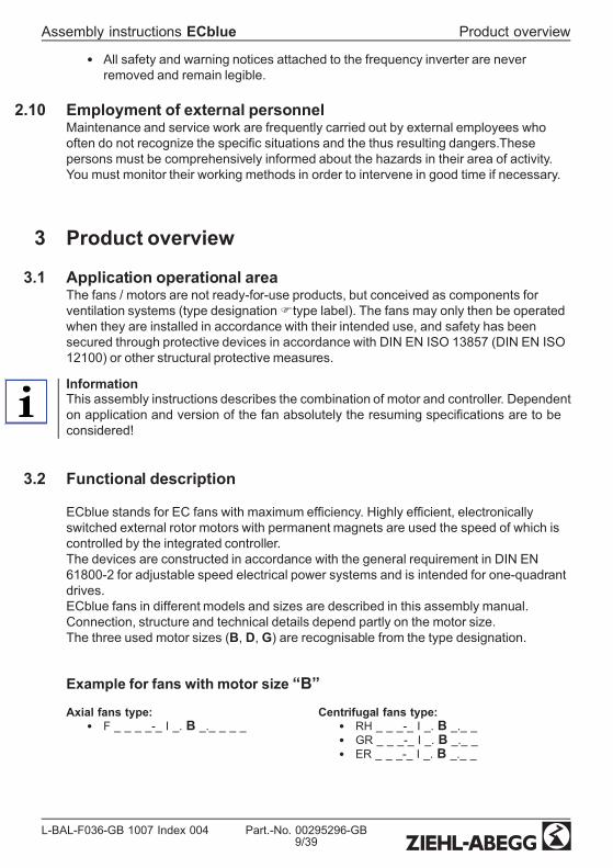
• All safety and warning notices attached to the frequency inverter are neverremoved and remain legible.
2.10 Employment of external personnelMaintenance and service work are frequently carried out by external employees whooften do not recognize the specic situations and the thus resulting dangers.Thesepersons must be comprehensively informed about the hazards in their area of activity.You must monitor their working methods in order to intervene in good time if necessary.
3 Product overview
3.1 Application operational areaThe fans / motors are not ready-for-use products, but conceived as components forventilation systems (type designationFtype label). The fans may only then be operatedwhen they are installed in accordance with their intended use, and safety has beensecured through protective devices in accordance with DIN EN ISO 13857 (DIN EN ISO12100) or other structural protective measures.
InformationThis assembly instructions describes the combination of motor and controller. Dependenton application and version of the fan absolutely the resuming specications are to beconsidered!
3.2 Functional description
ECblue stands for EC fans with maximum efciency. Highly efcient, electronicallyswitched external rotor motors with permanent magnets are used the speed of which iscontrolled by the integrated controller.The devices are constructed in accordance with the general requirement in DIN EN61800-2 for adjustable speed electrical power systems and is intended for one-quadrantdrives.ECblue fans in different models and sizes are described in this assembly manual.Connection, structure and technical details depend partly on the motor size.The three used motor sizes (B, D, G) are recognisable from the type designation.
Example for fans with motor size “B”Axial fans type:
• F _ _ _ _-_ I _. B _._ _ _ _Centrifugal fans type:
• RH _ _ _-_ I _. B _._ _• GR _ _ _-_ I _. B _._ _• ER _ _ _-_ I _. B _._ _
Assembly instructions ECblue Product overview
L-BAL-F036-GB 1007 Index 004 Part.-No. 00295296-GB9/39
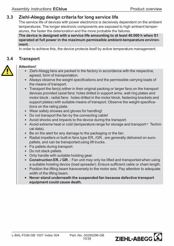
3.3 Ziehl-Abegg design criteria for long service lifeThe service life of devices with power electronics is decisively dependent on the ambienttemperatures. The longer electronic components are exposed to high ambient temper-atures, the faster the deterioration and the more probable the failures.The device is designed with a service life amounting to at least 40.000 h when S1operated at full power in the maximum permissible ambient-temperature environ-ment.In order to achieve this, the device protects itself by active temperature management.
3.4 TransportAttention!
• Ziehl-Abegg fans are packed in the factory in accordance with the respective,agreed, form of transportation.
• Always observe the weight specications and the permissible carrying loads ofthe means of transport.
• Transport the fan(s) either in their original packing or larger fans on the transportdevices provided (axial fans: holes drilled in support arms, wall ring plates andmotor block ; radial fans: holes drilled in the motor block, fastening brackets andsupport plates) with suitable means of transport. Observe the weight specica-tions on the rating plate.
• Wear safety showes and gloves for handling!• Do not transport the fan by the connecting cable!• Avoid shocks and impacts to the device during the transport.• Avoid extreme heat or cold (temperature range for storage and transportF Techni-cal data).
• Be on the alert for any damage to the packaging or the fan.• Radial impellers or built-in fans type ER../GR.. are generally delivered on euro-pallets, and can be transported using lift trucks.
• Fix pallets during transport.• Do not stack pallets.• Only handle with suitable hoisting gear.• ConstructionER../ GR..: Fan unit may only be lifted and transported when usinga suitable hoisting device (load spreader). Ensure sufcient cable or chain length.
• Position the lifting beam transversely to the motor axis. Pay attention to adequatewidth of the lifting beam.
• Never stand underneath the suspended fan because defective transportequipment could cause death.
Assembly instructions ECblue Product overview
L-BAL-F036-GB 1007 Index 004 Part.-No. 00295296-GB10/39
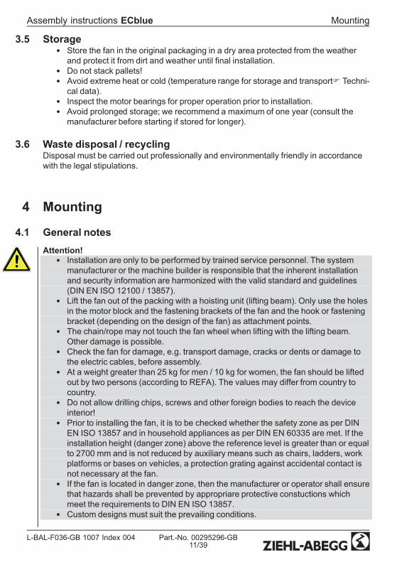
3.5 Storage• Store the fan in the original packaging in a dry area protected from the weatherand protect it from dirt and weather until nal installation.
• Do not stack pallets!• Avoid extreme heat or cold (temperature range for storage and transportF Techni-cal data).
• Inspect the motor bearings for proper operation prior to installation.• Avoid prolonged storage; we recommend a maximum of one year (consult themanufacturer before starting if stored for longer).
3.6 Waste disposal / recyclingDisposal must be carried out professionally and environmentally friendly in accordancewith the legal stipulations.
4 Mounting
4.1 General notesAttention!
• Installation are only to be performed by trained service personnel. The systemmanufacturer or the machine builder is responsible that the inherent installationand security information are harmonized with the valid standard and guidelines(DIN EN ISO 12100 / 13857).
• Lift the fan out of the packing with a hoisting unit (lifting beam). Only use the holesin the motor block and the fastening brackets of the fan and the hook or fasteningbracket (depending on the design of the fan) as attachment points.
• The chain/rope may not touch the fan wheel when lifting with the lifting beam.Other damage is possible.
• Check the fan for damage, e.g. transport damage, cracks or dents or damage tothe electric cables, before assembly.
• At a weight greater than 25 kg for men / 10 kg for women, the fan should be liftedout by two persons (according to REFA). The values may differ from country tocountry.
• Do not allow drilling chips, screws and other foreign bodies to reach the deviceinterior!
• Prior to installing the fan, it is to be checked whether the safety zone as per DINEN ISO 13857 and in household appliances as per DIN EN 60335 are met. If theinstallation height (danger zone) above the reference level is greater than or equalto 2700 mm and is not reduced by auxiliary means such as chairs, ladders, workplatforms or bases on vehicles, a protection grating against accidental contact isnot necessary at the fan.
• If the fan is located in danger zone, then the manufacturer or operator shall ensurethat hazards shall be prevented by appropriare protective constuctions whichmeet the requirements to DIN EN ISO 13857.
• Custom designs must suit the prevailing conditions.
Assembly instructions ECblue Mounting
L-BAL-F036-GB 1007 Index 004 Part.-No. 00295296-GB11/39

• Tighten the fastenings with the specied torques.• Any use below -10 °C is dependent on not being subjected to unusual, sudden ormechanical loads or stresses on the material (min. ambient temperatureF Tech-nical data).
4.2 Connection lead & terminal boxInformationIn demanding environments (wet areas, open air installation) all connections mustincorporate water drainage curves. To ensure that water cannot penetrate through to thecontroller housing from the connections install a terminal box lower than ventilator.
Assembly instructions ECblue Mounting
L-BAL-F036-GB 1007 Index 004 Part.-No. 00295296-GB12/39

4.3 Installation of axial fans
4.3.1 Fan designs A, D, K, S and W (without nozzles)For attachment to xed motor ange use screws with property class 8.8 or A2-70(stainless steel) to DIN EN ISO 4014 and provide with suitable screw locking.
Permissible tightening torques MAMotor size B D D G
Thread size M6M6
(Special applicationwith 5-pitch)
M8 M10
Property class 8.8, friction coefcientµges = 0.12
9 Nm 9,5 Nm 23 Nm 40 Nm
Stainless steel A2-70, friction coef-cient µges = 0.12 7 Nm 7 Nm 17 Nm 33 Nm
Screw penetration ≥ 1,07 x d ≥ 1,5 x d ≥ 1,5 x d ≥ 1,5 x d
When using screws with different friction values or strength classes, different tighteningtorques may be necessary.
Information• Pay attention to a sufcient screw-in length in the motor ange.• Motor size B: Excess screw length of max. 3 mm is permissible.• Motor size “D” + “G”: Excess screw length not permissible and it may result in therotor being brushed against or blocked.
• Do not install without adequate support. Mounting surface must be even.• In the case of a vertical motor axis, the respective lower condensation drain holemust be open.
• Fasten the fan connecting cable using cable ties to the guard grille or motorbraces.
A minimum head gap “A” of 2 mm in all installationpositions but especially in installation position H (hor-izontal motor shaft) is necessary. Distortion due touneven surface may lead to fan failure due to brush-ing against the fan wheel.
Assembly instructions ECblue Mounting
L-BAL-F036-GB 1007 Index 004 Part.-No. 00295296-GB13/39

4.3.2 Installation in an exhaust air stack, design T
gure 1
Mark the mounting bracket (4) in accordance with g. 1in the chimney (3) using a 4x90° template, drill holecenter distance “a” in accordance with the mountingbracket (4).
Fan sizeAdjustable diameter areamin. max.
F_063 640 660F_071 725 745F_080 815 835F_091 915 935
Tighten the mounting bracket (4) and the support bracket (5) g. 2 with screws (6) onlyso far that the mounting bracket and support bracket do not dig into the chimney wall (3).Self-locking nuts (7) are used for securing the screws. The enclosed protective caps (8)are to be pushed onto the ends of the fan supports (1), g. 2.
1819/104
57
6
3ai_kl_1905_1
gure 2
gure 3
Assembly instructions ECblue Mounting
L-BAL-F036-GB 1007 Index 004 Part.-No. 00295296-GB14/39

Feed the fan (1) into the chimney in accordance with g. 3, and center it in the mountingbracket (4). In addition, the support is to be secured in accordance with g. 2 by usingbolts (9/10).The four support clamps (5) are used as support eyelets for additional xings (e.g. bystanding ropes) in order to relieve the chimney of the weight of greater fans.
Installation set (Part.-No. 00291545)
Pos. Naming Each1 Axial fan -3 Chimney -4 Mounting bracket 45 Support bracket 46 M8x70 screws DIN EN ISO 4014 87 M8 nuts DIN EN ISO 10511 self-locking 87a 8.4 washer DIN EN ISO 7089 88 Protective cap 49 M8x30 screws DIN EN ISO 4017 410 M8 nuts DIN EN ISO 10 511 self-locking 410a 8.4 washer DIN EN ISO 7089 4
All fastening elements made of stainless steel
Assembly instructions ECblue Mounting
L-BAL-F036-GB 1007 Index 004 Part.-No. 00295296-GB15/39

4.4 Installation of centrifugal fans
4.4.1 Assembly of centrifugal fans, RH designFor attachment to xed motor ange use screws with property class 8.8 to DIN EN ISO4014 and provide with suitable screw locking.
Permissible tightening torques MAMotor size B D D G
Thread size M6M6
(Special applicationwith 5-pitch)
M8 M10
Property class 8.8, friction coefcientµges = 0.12
9 Nm 9,5 Nm 23 Nm 40 Nm
Screw penetration ≥ 1,07 x d ≥ 1,5 x d ≥ 1,5 x d ≥ 1,5 x d
When using screws with different friction values or strength classes, different tighteningtorques may be necessary.
Information• Pay attention to a sufcient screw-in length in the motor ange.• Motor size B: Excess screw length of max. 3 mm is permissible.• Motor size “D” + “G”: Excess screw length not permissible and it may result in therotor being brushed against or blocked.
• Do not install without adequat support. Flange and mounting bracket must bexed at on a level surface.
• In the case of a vertical motor axis, the respective lower condensation drain holemust be open.
• The fan must be securely mounted, with vibration dampers if necessary.
Ensure that the clearance (gap) “a” see g. be-tween the fan impeller and the stationary housingsection is constant. Distortion due to uneven sur-face may lead to fan failure.
Assembly instructions ECblue Mounting
L-BAL-F036-GB 1007 Index 004 Part.-No. 00295296-GB16/39

4.4.2 Erecting the equipment: Design ER...-..N... / ER...-..K... / GR...• To avoid the transference of disruptive vibrations, we recommend de-coupling theentire plug fan to avoid sounds transmitted through solids. (Spring and/or attenu-ation units are not a constituent part of the standard scope of delivery). Look atour catalogue for positioning the decoupling elements or request a dimensionssheet stating the type designation and Part.-No.
• Caution: All contact points must be xed securely. If the xing is inadequatethere is a risk of the fan overturning.
• Erect in the open air only if this is expressly mentioned and conrmed in theordering information. There is a risk of damage to the bearings if the fan remainsstopped in a moist environment. Avoid corrosion by suitable protective measures.Roong is required.
• Making your own alterations/conversions on the fan module is unacceptable -safety risk.
• In the case of a vertical motor axis, the respective lower condensation drain holemust be open.
4.4.3 Optimal installation distances according to for RH.. / ER fans
• Distance on suction side: LA ≥ 0.5 x DSa*• Distance on the pressure side: LD ≥ 1 x DSa• Impeller blade external-diameter : Ø DSa• Housing wall distances: A = 1,8 x DSa (A = B)
* In the case of disturbance ow (per example curved pipe at the suction side, aps etc.)LA ≥ 1 x DSa
4.5 Outdoor fans in a humid atmosphereInformationIf a fan is stationary for long periods in a humid atmosphere, it should be switchedON for minimum of two hours every month to remove any moisture that may havecondensedwithin the motor.
Assembly instructions ECblue Mounting
L-BAL-F036-GB 1007 Index 004 Part.-No. 00295296-GB17/39

4.6 MotorheatingTo prevent a stationary ventilator in a cold environment from jamming or freezing, theMotorheating becomes automatically active at a controller interior temperature of -19 °C.
5 Electrical installation
5.1 Safety precautionsDanger owing to electric current
• Work on electric componentsmay only be carried out by trained electriciansor by persons instructed in electricity under the supervision of an electricianin accordance with electrical engineering regulations.
• The 5 electrical safety rules must be observed!• It is forbidden to carry out work on electrically live parts. Even after discon-nection, the dc-link is still live. Always wait at least 3 minutes.
• A second person must always be present when working on energized partsor lines who disconnects in case of emergency.
• Connect fan only to electrical circuits that can be disconnected with an all-pole isolating switch.
• The device owner is responsible for the EMC of the entire plant according tothe locally applicable standards.
• Inspect electrical equipment periodically: retighten loose connections –immediately replace damaged lines and cables.
5.2 ConnectionInformationThe respective connections are represented in the enclosure of this assemblyinstructions (F Connection diagram)!
Assembly instructions ECblue Electrical installation
L-BAL-F036-GB 1007 Index 004 Part.-No. 00295296-GB18/39

5.2.1 Motor size “B”
Fans with cable connection (type: _ _ _ _ _-_ I _. B _._ _ _ _)
GN
YE
= PE
BU
= N
BN
= L1
WH
= 11
WH
= 141
2
0.6 m
RD
= 10 V D
C O
ut
GN
= D1 D
igital In
BU
= GN
D
GY
= A2 Status O
ut OC
YE
= E1 A
nalog In
WH
= A1 Tacho O
ut OC
0.6 m
3
17.11.2009v_anschl_ecblue_096.vsd
1 Connection line and relay: light plastic-sheathed cable 18 AWG (length ca. 0.6 m)2 Connection control: light plastic-sheathed cable 22 AWG (length ca 0.6 m)3 Connection cover
InformationAn exchange of the motor / fan should always take place with the connection leads!The connection cover may not be opened!
• The leads in this illustration are assigned to terminal designations with referenceto their function. Some of these are used in the following chapters.
• Extension through separate connecting box for each connecting line only.• Connecting boxes and connectors are not included in the package contents.
Assembly instructions ECblue Electrical installation
L-BAL-F036-GB 1007 Index 004 Part.-No. 00295296-GB19/39

5.2.2 Motor size “D” and “G”
Fans with connection box (type: _ _ _ _ _-_ I _. D _._ _ _ _), (type: F _ _ _ _-_ I _. G _.__ _ _)
1
2
4 5 6
7
3
11 14
P E
P E
26 . 11 . 2009 v _ anchluss _ ecblue . vsd
L 1 L 2 L 3 L 1 N
1 3 6 0 - 3 6 0 V o r N ä s s e u n d S c h m u t z s c h ü t z e n K e e p d r y a n d p r o t e c t f r o m d i r t
3 ~ N a c h E N 5 0 1 7 8 i s t b e i V e r w e n d u n g e i n e s F I - S c h u t z s c h a l t e r s e i n a l l s t r o m s e n s i t i v e r z w i n g e n d v o r g e s c h r i e b e n 3 ~ f o r a n i n s t a l l a t i o n o f r . c . d p r o t e c t i o n i t s h a l l b e o b s e r v e d t h a t t h i s m u s t b e o f u n i v e r s a l - c o r r e n t s e n s i t i v i t y i n a c c o r d a n c e w i t h E N 5 0 1 7 8
2 4 V 1 0 V G N D D 1 E 1 1 1 1 4
K 1
L 1
L 1
L 2 L 3
N
D C
O u t
( I m
a x 7 0
m A )
D C
O u t
( I m
a x 1 0
m A )
A n a l
o g I n
( 0
. . . 1 0 V
/ P W
M )
D i g
i t a l I n
K o n t a k t b e l a s t u n g C o n t a c t r a t i n g
m a x . A C 2 5 0 V 2 A
N e t z s p a n n u n g L e i s t u n g s s c h i l d L i n e v o l t a g e R a t i n g - p l a t e
3 ~ T y p n i c h t f ü r I T - N e t z g e e i g n e t
3 ~ t y p e n o t s u i t a b l e f o r I T n e t w o r k
P E P E P E L 1 L 2 L 3 / N
+ 2 4
V
+ 1 0 V
G
N D
D
1 E
1
1 Cover of controller housing2 3 cable glands
(3 x M16 motor size “D”, 3 x M20 motor size “G”) included3 Cable entry points with plastic fastener4 Mains connection5 Connection alarm relay6 Connection contols7 Slot for add-on module
Procedure:1. Remove the cover from the controller housing for the connection.2. All 3 cable entry points are in a sealed condition at delivery. Remove plasticfastener if necessary, and insert cable gland, entry points that are not used mustremain sealed!
3. Insert and connect lines correctly.4. Attach cover of controller housing again carefully in correct position before start-up.
Attention!• Temperatures up to 85 °C can be present on the controller housing.• To connect, always use heat resistant wires or, as an alternative, silicon tubes.• Self-tapping screws are used for the “PE” conductor connection. These cannot beloosened and sufceintly retightened innitely.
• Remants from installation und foreign object may not remain on the inside!
Assembly instructions ECblue Electrical installation
L-BAL-F036-GB 1007 Index 004 Part.-No. 00295296-GB20/39

Permissible tightening torques MA
Thread size Tightening tor-que MA
Remark
Cable gland M16 2.5 Nm Sealing area for cable diameter 4…10 mmCable gland M20 4 Nm Sealing area for cable diameter 6…12 mmLocking screw M16 + M20 1.25 Nm Phillips screwdriverLocking screw M16 + M20 2.5 Nm Flat screwdriverCover of controllerhousing M4 2.3 Nm
Protective groundconnection M4 2.5 Nm
Add-on module M4 1.3 Nm
Max. cross section of terminals
Mains connection: L1, N and/ or L1, L2, L3 max. 2.5 mm2 and/or AWG12Connection control: +24 V, +10 V, GND, D1, E1, K1 max. 1.5 mm2 and/or AWG16Add-on modules: 1.5 mm2 (0.75 mm2 with wire end sleeve)
and/or AWG16
5.3 EMC-compatible installation of control linesPay attention to sufcient distance from powerlines and motor wires to prevent interfer-ences. The control cable may not be longer than 30 m. Screened control cables must beused when the cable length is longer than 20 m. When using a shielded cable connectthe shielding to one side only, i.e. only to the device with the protective ground (keepcable short and with as little inductance as possible!).
5.4 Mains connection
5.4.1 Line voltage for 1~ typesMains connection: PE, L1, and N. Here, it must be strictly observed that the mainsvoltage lies within the allowable tolerance specications (F technical data).
Alternatively a supply of DC voltage is possible (F Technical data).The polarities on “L1” and “N” are irrelevant.
5.4.2 Line voltage for 3~ typesMains connection: PE, L1, L2 and L3. Here, it must be strictly observed that the mainsvoltage lies within the allowable tolerance specications (F technical data).
Alternatively a supply of DC voltage is possible (F Technical data).Connect to any two terminal clips for “L1”, “L2” and “L3”, the polarity is irrelevant.
Assembly instructions ECblue Electrical installation
L-BAL-F036-GB 1007 Index 004 Part.-No. 00295296-GB21/39
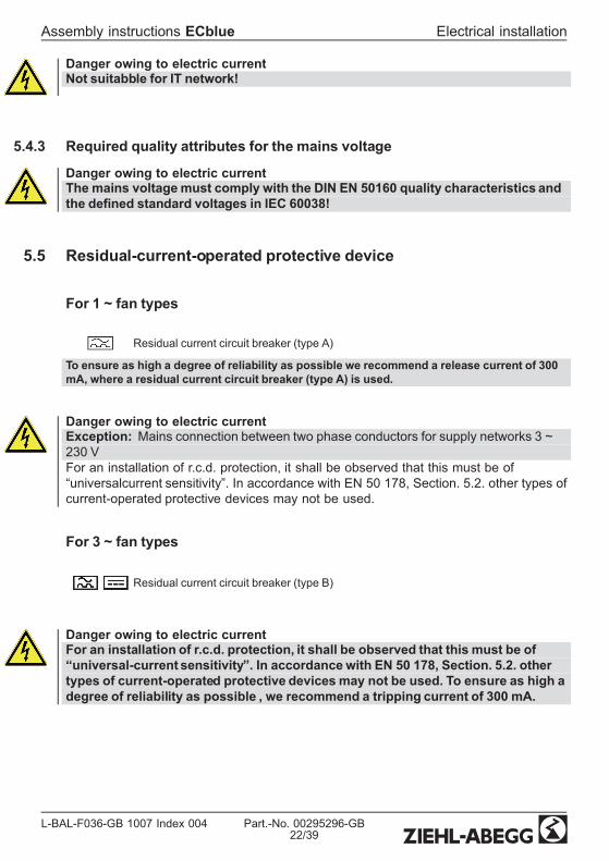
Danger owing to electric currentNot suitabble for IT network!
5.4.3 Required quality attributes for the mains voltage
Danger owing to electric currentThe mains voltagemust comply with the DIN EN 50160 quality characteristics andthe dened standard voltages in IEC 60038!
5.5 Residual-current-operated protective device
For 1 ~ fan types
Residual current circuit breaker (type A)
To ensure as high a degree of reliability as possible we recommend a release current of 300mA, where a residual current circuit breaker (type A) is used.
Danger owing to electric currentException: Mains connection between two phase conductors for supply networks 3 ~230 VFor an installation of r.c.d. protection, it shall be observed that this must be of“universalcurrent sensitivity”. In accordance with EN 50 178, Section. 5.2. other types ofcurrent-operated protective devices may not be used.
For 3 ~ fan types
Residual current circuit breaker (type B)
Danger owing to electric currentFor an installation of r.c.d. protection, it shall be observed that this must be of“universal-current sensitivity”. In accordance with EN 50 178, Section. 5.2. othertypes of current-operated protective devices may not be used. To ensure as high adegree of reliability as possible , we recommend a tripping current of 300 mA.
Assembly instructions ECblue Electrical installation
L-BAL-F036-GB 1007 Index 004 Part.-No. 00295296-GB22/39

5.6 Motor protectionIntegrated overload protection, preceding motor protection device unnecessary (max.prefusingFTechnical details).
5.7 Analog input (0...10 V) for setting fan speedThe unit has an analog input 0...10 V for setting fan speed.Connection “GW E1 Viive” / “GND” (Analog In 1).Alternatively speed setting with a PWM-signal is possible.
Attention!Ensure correct polarity!Never apply line voltage to analog inputs!
Possibilities for speed setting
0...10 V+
GND E1• Control via external setting signal 0...10 V• By external wiring with a resistor (499 Ω / 0,25 W) between theterminals “E1” and “GND” parallel to the input signal, activationwith a 0...20 mA signal is possible.
• The “AM-Modbus” communication module enables a invertedset-point signals to be programmed (10...0 V).
10V GND E1
10 kΩ
• Speed setting by 10 kΩ potentiometer at terminals “+10 V” and“GND” pick-off at terminals “E1”.
10V GND E124V
PWMf = 1...10 kHz
10 kΩ
10 V
GN
D E1
24 V E1
E1
GN
D
15...28 V
+-
• Control by external setting signal PWM (connection “24 V” onlyfor motor sizes “D” and “G” available).
Assembly instructions ECblue Electrical installation
L-BAL-F036-GB 1007 Index 004 Part.-No. 00295296-GB23/39

Diagram Setting signal and fan speed (Idealized principle diagram)nM
100 %
0 1 2 3 4 5 6 7 8 9 100 10 20 30 40 50 60 70 80 90 100
0 – 10 V0 – 100 % PWM
20.04.2009v_nmotor@0_10v_pwm.vsd
Si
nM Fan speedSi Speed setting signal 0...10 V / 0...100 % PWM
5.8 Output voltage +10 VVoltage supply e.g. for speed setting by external potentiometer.Connection: “DC Out” - “GND” (Imax 10 mA).It is not permissible to connect outputs of several devices to each other!
5.9 Voltage supply for external devices, only motor sizes “D”, “G”(+24 V, GND)Integrated voltage supply for external devices. Terminals “+ 24 V”(FTechnical data).It is not permissible to connect outputs of several devices to each other!During an overload or short-circuit (24 V - GND), the control voltage (and thus the device)is disconnected . Automatic start after elimination of the cause of error.
5.10 Enable, device ON / OFF (Digital In 1 = D1)Electronic disconnection and Reset after fault via oating contact at terminals“D1” - “+24V” / “+10V”
• Device “ON” for closed contact.• Controller “OFF” with opened contact.• Relais “K1” remains energized, connections 11 - 14 bridged.For motor size “D”,“G” the signal lamp ashes in code |1| (FDiagnostics / Faults).
Attention!• No disconnection (isolation)when turned off by remote, in accordance withVBG4 §6)!
• Never apply line voltage to the digital input!• It is not permissible to connect inputs of several devices to each other!
Assembly instructions ECblue Electrical installation
L-BAL-F036-GB 1007 Index 004 Part.-No. 00295296-GB24/39

5.11 Relay outputs (K1)An external fault indicator is available over the potential-free contact of the built-in relay(max. contact ratingFTechnical data and connection diagram).For operation the relay is energized, connections “11” and “14” are bridged. For fault therelay is de-energized (FDiagnostics / faults).When switching off via enable (D1 = Digital In 1), the relay remains energized.
5.12 Tacho outIn motor size “B” a frequency signal can be output at output “A1 Tacho Out OC”. Thissignal serves to evaluate the current speed of the fan.(Functional description obtainable from the Ziehl-Abegg Support DepartmentF Servicenote)
In engine size “D” and “G” the tachometer output is on the additional module “AM-MODBUS”.
5.13 Output Status Out OC (motor size “B”)Via the output “A2 Status Out OC” an additional operating message is possible inmotor size “B”.The OC (Open-Collector) output is on GND potential during operation. Whenusing the output voltage “+10 V” a LED can be controlled by a pull-up resistor (>4.7 kΩ).
01.03.2010v_ecblue_096_status_out_led.vsd
Pull Up
10V
DC
Out
A2
Stat
us
Out
OC
5.14 Potential at control voltage connectionsThe control voltage connections (< 50 V) relate to the joint GND potential (Exception:Relay contacts are potential free). There is a potential separation between the controlvoltage connections and the earthed conductor. It must be ensured that the maximumexternal voltage at the control voltage connections cannot exceed 50V (between “GND”terminals and “PE” earthed conductor). If necessary, a connection to the earthed con-ductor potential can be established, install bridge between “GND” terminal and the “PE”connection (terminal for screening).
5.15 Add-onmodulesThe assembly instructions available here describe the “basic version”.If required, an auxiliary module can be retrotted to the designated slot for motor size“D”, “G”. The auxiliary module is installed automatically. Manual installation or parameter-isation is not required!For fans of motor size “B” separate versions with integrated add-on modules areavailable.The extended scope of function is specied in the documentation for the auxiliarymodule.
Assembly instructions ECblue Electrical installation
L-BAL-F036-GB 1007 Index 004 Part.-No. 00295296-GB25/39

The range of additional modules is constantly being extended and adapted to marketrequirements. The currently available additional modules can be requested from Ziehl-Abegg.
Examples for currently available additional modules
Type Part.-No. FunctionAM-MODBUS(for motor size “D”and “G”)
349045 Communication moduleOver the “AM-MODBUS”module can be communicated withthe controller of the fan. The module can be put in temporarilyfor programming of desired functions during start-up or fordiagnostics. The connection to the control terminal is made bya connecting cable or wirelessly by means of radio.The module is left in the slot if it is to be integrated into amodule bus system or networked to several devices. Theaddressing of ECblue fans takes place automatically, i.e. it isnot necessary to manually enter individual network addressesfor each fan.
AM-PREMIUM(for motor size “D”and “G”)
349046 Premium ModuleWhen the “AM-PREMIUM” is plugged in the controller in thefan is extended to become a full-grade multipurpose controller.The “Premium module” provides not only an integrated modulebus interface, it also enables sensors to be connected straightto the fan.The module also comes with two analogue inputs and oneanalogue output.
6 Start-up
6.1 Prerequisites for commissioningDuring commissioning, unexpected and hazardous conditions can arise in the entireinstallation due to defective adjustments, defective components or incorrect electricalconnections. Remove all persons and objects from the hazardous area.
Attention!• Before rst-time start-up, check the following:1. Installation and electrical connection have been properly completed?2. Has any leftover installation material and other foreign material been removedfrom the fan area?
3. That safety devices -if necessary- are mounted (EN ISO 13857)?4. The impeller is out of reach?5. Installation position and the arrangement of condensation water drainscorrespond to each other?
6. Connection data complies with the specications on the type plate?
Assembly instructions ECblue Start-up
L-BAL-F036-GB 1007 Index 004 Part.-No. 00295296-GB26/39

• Commissioningmay only take place if all safety instructions have beenchecked and danger can be excluded.– Check the direction of rotation (F rotation direction arrow on the fan blade,impeller base plate or on the fan housing).
– Check for quiet, low vibration operation. Strong vibrations due to erraticoperation (unbalanced), e.g. caused by transportation damage or improper use,can lead to failure.
– A-rated sound power levels of over 80 dB(A) are possible, see productcatalogue.
– Check for mechanical vibrations after installation into the system. If thetolerances according to DIN Iso 10816-1 are exceeded, it is possible to excludecertain speed ranges (F Motor Setup or add-on module).
7 Diagnostics / Faults
7.1 Trouble shooting
Type of error Possible cause Remedial measuresFan does not run(anymore)
Failure line voltageFailure of one phaseUnder - or overvoltage
check line voltage
Shortcut Earth Check motor connection and line voltageShort circuit winding Replace fanThermal motor protectionhas triggered (motor isoverheated)
Check for free air passages; remove foreign bodies ifnecessaryF "Impeller blocked or dirty"Check temperature of supply airchec voltage
Impeller blocked or dirty - Switch off power to the motor and secure againstswitching back on- heck safe isolation from supply- Remove safety grille- Remove foreign bodies or soiling- Remount the safety grille- Further procedure as in the chapter “Start-up”
fan will not start Temperature too low forbearing grease
Insert bearing with cold greasing
Air stream wrong direction(Motor turns in wrong direc-tion at high speed)
Check air stream
F "Fan does not run"Fan turns too slowly Impeller / blade scrapes /
brushesClear foreign bodies/dirt from the fan
Assembly instructions ECblue Diagnostics / Faults
L-BAL-F036-GB 1007 Index 004 Part.-No. 00295296-GB27/39

Type of error Possible cause Remedial measuresActive temperature man-agement effective(Motor or electronics over-heated)
Check for free air passages; remove foreign bodies ifnecessaryF "Impeller blocked or dirty"Check temperature of supply airCheck installation space (air speed over heat sink)
Air ow to low Fan turns too slowly F
Airways blocked Check for free air passages (supply/exhaust air vents,lters)F "Impeller blocked or dirty"
Pressure loss different toplanned
Check fan selection
Vibrations Imbalance Check blades for damage, soiling or iceF "Impellerblocked or dirty"
No or wrong vibrationdampers (only in radial)
Install correct vibration dampers
Unusual noises Bearing damaged / worn Change bearingsImpeller / blade scrapes /brushes
Clear foreign bodies / dirt from the fanF "Impellerblocked or dirty"
Operation beyond stallpoint(for axial fans)
Check for free air passages (supply/exhaust air vents,lters)
Wrong overlap on nozzle(for centrifugal fans)
Observe the installation instructions
Assembly instructions ECblue Diagnostics / Faults
L-BAL-F036-GB 1007 Index 004 Part.-No. 00295296-GB28/39

7.2 For motor size “D” and “G” Status LED with ash code
23.04.2009v_led_status_ecblue.vsd
11.02.2009v_flash_explain.VSD
3 x
2 x
ON
OFF
4 x
5 x
6 x
1 x
7 x
8 x
9 x
LED Code(only D, G)
Relays K1(for function fac-tory setting)
CauseExplanation
Reaction of ControllerAdjustment
OFF de-energized, 11- 14 interrupted no line voltage
Line voltage available?Unit switches OFF and automaticallyON when the voltage has been re-stored
ON energized, 11 - 14bridged Normal operation without fault
1 x energized, 11 - 14bridged
no enable = OFF
Terminals “D1” - “24 V / 10 V” (DigitalIn 1) not bridged.
Switch OFF by external contact (Fdigital input).
2 x energized, 11 - 14bridged
Active temperature managementThe device has an active tempera-ture managementto protect it fromdamage due to too high inside tem-peratures. In case of a temperaturerise above the xed limits, the modu-lation is reduced linearly. To preventthe complete system being switchedoff externally (in this operation per-missible for the controller) in case ofreduced operation due to too high aninternal temperature, no fault mes-sage is sent via the relay.
At sinking temperature the modula-tion rises again llinear.Check cooling of the controller
3 x de-energized, 11- 14 interrupted
HALL-ICIncorrect signal from the Hall-ICs,error in the commutation.
Controller turns the motor off. Auto-matic restart if no more fault is recon-gized.
Assembly instructions ECblue Diagnostics / Faults
L-BAL-F036-GB 1007 Index 004 Part.-No. 00295296-GB29/39

LED Code(only D, G)
Relays K1(for function fac-tory setting)
CauseExplanation
Reaction of ControllerAdjustment
4 x de-energized, 11- 14 interrupted
Line failure (only for 3 ~ types)The device is provided with a built-inphase-monitoring function for themains supply. In the event of a mainsinterruption (failure of a fuse ormains phase) the unit switches offafter a delay (approx. 200 ms).Function only when load for the con-troller is high enough.
Following a shutoff, a startup attemptis made after approximately 15 sec-onds, if the voltage supply is highenough. This keeps occurring untilall 3 supply phases are availableagain.Checking power supply
5 x de-energized, 11- 14 interrupted
Motor blockedIf after 8 seconds cummutation nospeed is measured > 0, the fault“Motor blocked” is released.
EC-Controller switches off, renewedattempt to start after about 2.5 sec.Final shutoff, when fourth startingtest fails. It is then necessary to havean enabling reset or to disconnectthe power supply.Check if motor is freely rotatable.
6 x de-energized, 11- 14 interrupted
IGBT FaultShortcut earth or shortcut of motorwinding.
EC-Controller switches off, renewedattempt to start after about 60 sec.FCode 9Final shutoff, if - following a secondstarting test – a second fault detec-tion is detected within a period of 60seconds.It is then necessary to have an ena-bling reset or to disconnect thepower supply.
7 x de-energized, 11- 14 interrupted
DC undervoltageIf the intermediate circuit voltagedrops below a specied limit, the de-vice is shutoff.
If the intermediate circuit voltagerises again within 75 seconds abovethe limit, an automatic starting test isrun.If the intermediate circuit voltage re-mains below the limit for more than75 seconds, the device is shutoffwith a fault message.
8 x de-energized, 11- 14 interrupted
DC overvoltageIf the intermediate circuit voltage in-creases above the specied limit themotor is switched off.Reason for excessively high inputvoltage or alternator motor operation.
If the intermediate circuit voltagedrops again within 75 seconds belowthe limit, an automatic starting test isrun.If the intermediate circuit voltage re-mains above the limit for more than75 seconds, the device is shutoffwith a fault message.
9 x energized, 11 - 14bridged
IGBTcooling down periodIGBT cooling down period for approx.60 sec.Final shutoff after 2 cooling-off inter-valsF Code 6
Assembly instructions ECblue Diagnostics / Faults
L-BAL-F036-GB 1007 Index 004 Part.-No. 00295296-GB30/39

8 Service work
8.1 Repairs / maintenanceAttention!
• Allowmaintenancework to be carried out by trained specialists only.• Please observe the safety regulations and the worker´s protection rules byall maintenance and service work (DIN EN 50 110, IEC 364).
• Before working on the fan, this must be disconnected from the power supplyand secured against switching back on!
• Keep the airways of the fan free - danger because of objects dropping out!• No maintenance work at running fan!• Watch out for vibration free motion!• Depending on the application and the transfer medium the impeller has anatural wear. Deposits on the impeller can lead to imbalance and thus todamages (danger of endurance fracture). The impeller can disintegrate!
• Maintenance interval in accordance with the degree of contamination of theimpeller!
• In case of imbalance: Rebalancing the impeller.• Check the impeller, in particular the weld-seams, for possible cracks.• Repair, e.g. by welding is prohibited!• The fan or motor is maintenance free through the usage of ball bearings with “life-time lubrication”. After the end of the grease service-life (ca. 30-40,000 h duringstandard usage), an exchange of the bearing is necessary. For this as well as forall other defects (e.g. on the winding or in the electronics), please contact ourservice department.
• Bolted-on wheels and/or wings may only be replaced by authorised Ziehl-AbeggAG staff. The manufacturer shall not be liable for damage caused throughimproper repair work.
• Regular inspection, and cleaning is necessary to prevent imbalance due to ingressof dirt.
Assembly instructions ECblue Service work
L-BAL-F036-GB 1007 Index 004 Part.-No. 00295296-GB31/39

8.2 CleaningDanger owing to electric currentVoltage supply for motor must be interrupted and secured against restoration!
Attention!• Do not use any aggressive, paint solvent cleaning agents when cleaning.• Cleaning with a water jet:
– Make sure that no water gets into the inside of the motor, note protection class(IP).
– Do not hold the jet spray directly on the motor openings and seals.– During cleaning work using a jet spray, no guarantee is assumed regardingcorrosion formation / paint adhesion for unpainted / painted fans.
– After the cleaning process, the fan must be operated for 30 minutes at 80 to100 % of maximum speed for drying purposes!
9 Enclosure
9.1 Technical data
Line voltage*(F Rating-plate)
AC: 1 ~ 200...277 V (+/- 10 % ),50/60 Hz
DC: 280...400 V (+/- 10 % )
AC: 3 ~ 200...240 V (+/- 10 % ),50/60 Hz
DC: 280...340 V (+/- 10 % )
AC: 3 ~ 380...480 V (+/- 10 % ),50/60 Hz
DC: 500...680 V (+/- 10 % )
DC supply not UL® approved!Maximal line fuse 16 A for all types 1 ~ and 3 ~Max. cut-in current 126 AMax. load limit integral of cut-incurrent
1.22 A2s
Clock frequency 16 kHzInput resistance for signal set forthe rotational speed
Ri > 100 kΩ
Specication speed setting sig-nal PWM
Voltage: 15...28 VDCSwitching Frequency: 1...10 kHzOn-off ratio: 0...100 %
Voltage supply for external devi-ces
+ 10 V, I max 10 mA (short-circuit-proof)+24 V ±20 %, Imax 70 mA (only for motor size “D”, “G”)
Assembly instructions ECblue Enclosure
L-BAL-F036-GB 1007 Index 004 Part.-No. 00295296-GB32/39

Permissible minimal and maxi-mal ambient temperature for op-eration
-25 °C...60 °C (up to 70 °C **)Please see the technical documentation of the product for the minimumand maximum ambient temperature valid for the respective fan; Thesemay deviate from the specied permissible ambient temperatures.To avoid condensation, the drive must be connected permanently to themains.
Max. permissible installationheight
height 1000 m amsl without derating
Permissible rel. humidity 85 % no condensationPermissible temperature rangefor storage and transport
-30...+80 °C
Electromagnetic compatibility forthe standard voltage 230 / 400V according to DIN IEC 60038
Interference emission EN 61000-6-3 (domestic household applications)Interference immunity EN 61000-6-2 (industrial applications)
Harmonics current according For 1 ~ typesActive power factor adjustment for sinusoidal input current (PFC = Power- Factor - controller), harmonic current in accordance with EN 61000-3-2are guaranteed.For 3 ~ typesEN 61000-3-2 for a “professional unit”.Please ask Ziehl-Abegg for the individual harmonic oscillation levels ofthe current as a percentage of the fundamental oscillation of the ratedcurrent.
Contact rating of the internalrelay
AC 250 V 2 A
Max. leakage current accordingto the dened networks of DINEN 60990
< 3.5 mA
dB(A) values F product catalogProtection class of motor ac-cording DIN EN 60529
IP 54
* Regarding the mains connection, the devices are to be classied as category “C2” devicesaccording to the relevant DIN EN 61800-2 The increased requirements placed on electricalinterference for category “C1” devices are complied with in addition.
** In case of a temperature increase above the predetermined threshold values modulation islinearly reduced by active temperature management.
Assembly instructions ECblue Enclosure
L-BAL-F036-GB 1007 Index 004 Part.-No. 00295296-GB33/39

9.2 Connection diagramMotor size “B” (type: _ _ _ _ _-_ I _. B _._ _ _ _)
ECblue (_ _ _ _ _-_I_.B_._ _ _ _)
N L1PENetzLine
1 ~ 200...277 V50/60 Hz
10 kΩ
+
KT00044A11.03.2010
PE N L1
1Externe Drehzahlvorgabe
External speed setting
3
10 V
DC
Out
(Im
ax =
10
mA
)
D1
Dig
ital I
n 1
GN
D
A2
Sta
tus
Out
OC
GN
YE
BU
BN
RD
BU
GY
11 14
WH
WH
KontaktbelastungContact rating
max. AC 250 V 2 A
5
E1
Ana
log
In 1
A ID B GN
D
A ID B GN
D
YE
WH
GN
11 14
10 kΩ
10 V
GN
D E1
E1
GN
D
PWMf = 1...10 kHz
4
EingangInput
0...10 V
K1
15...28 V
+-
2
SignalanschlussSignal connection
A1
Tac
ho/E
rror
Out
OC
1 Line voltage 1 ~ 200...277 V, 50/50 Hz2 Signal connection3 Input 0...10 V4 PWM input, f = 1...10 kHz5 Contact rating max. AC 250 V 2 A
Assembly instructions ECblue Enclosure
L-BAL-F036-GB 1007 Index 004 Part.-No. 00295296-GB34/39

Motor size “D” and “G” (type: _ _ _ _ _-_ I _. D _._ _ _ _), (type: _ _ _ _ _-_ I _. G _._ _ _ _)
24V 10V GND D1 E1 11 14
DC
Out
(I max
= 7
0 m
A)D
C O
ut(I m
ax =
10
mA)
Dig
ital I
n 1
Ana
log
In 1
L3/NL2L1PE
L1
L2 L3
PE
L1
N
ECblue (_ _ _ _ _-_I_.D_._ _ _ _), (_ _ _ _ _-_I_.G_._ _ _ _)
MOEA03K011.03.2010
K1
KontaktbelastungContact rating
max. AC 250 V 2 A
Netzspannung LeistungsschildLine voltage Rating-plate
3 ~ Typ nicht für IT-Netz geeignet3 ~ type not suitable for IT network
EingangInput
0...10 V
+
PWMf = 1...10 kHz
Externe DrehzahlvorgabeExternal speed setting
5
3
4
1
2
10 kΩ
10 kΩ
10 V
GN
D E1
24 V E1
E1
GN
D
15...28 V
+-
1 Line voltage F Rating-plate (3 ~ type not suitable for IT network)2 Contact rating max. AC 250 V 2 A3 External speed setting4 Input 0...10 V5 PWM input, f = 1...10 kHz
Assembly instructions ECblue Enclosure
L-BAL-F036-GB 1007 Index 004 Part.-No. 00295296-GB35/39

9.3 EC Declaration of Incorporation ZA87-GB-12/09 Index 00000296702-GB
as dened by the EC Machinery Directive 2006/42/EC,Annex II B
The design of the incomplete machine:• Axial fan FA.., FB.., FC.., FE.., FS.., FT.., FH.., FL.., FN.., VR.., VN..• Centrifugal fan RA.., RD.., RE.., RF.., RG.., RH.., RK.., RM.., RR.., RZ.., GR..,ER..
• Cross ow fan QK.., QR.., QT.., QD.., QG..
Motor type:• Induction internal or external rotor motor (also with integrated frequency inverter)• Electronically commutated internal or external rotor motor (also with integrated ECcontroller)
complies with the requirements in Appendix I, Articles 1.1.2, 1.1.5, 1.4.1, 1.5.1 inEC Machinery Directive 2006/42/EC.
The manufacturer is theZiehl-Abegg AGHeinz-Ziehl-StraßeD-74653 Künzelsau
The following standards are applied:EN 60204-1:2006 Safety of machinery; electrical equipment of machines; Part 1: Gen-
eral requirementsEN ISO12100:2003
Safety of machinery; basic concepts, general principles for design
EN ISO13857:2008
Safety of machinery; safety distances to prevent danger zones beingreached by the upper limbs
Note: The maintenance of the EN ISO 13857:2008 relates only to theinstalled accidental contact protection, provided that it is part of thescope of delivery.
The specic technical documentation in accordance with Appendix VII B has beenwritten and is available in its entirety.
The person authorised for compiling the specic technical documentation is: Dr. O. Sadi,address see above.The specic documentation will be transmitted to the ofcial authorities on justiedrequest. The transmission can be electronic, on data carriers or on paper. All industrialproperty rights remain with the above-mentionedmanufacturer.
Assembly instructions ECblue EC Declaration of Incorporation
L-BAL-F036-GB 1007 Index 004 Part.-No. 00295296-GB36/39

It is prohibited to commission this incomplete machine until it has been securedthat the machine into which it was incorporated complies with the stipulations ofthe EC Machinery Directive.
Künzelsau, 29-Dec-2009Dr. O. Sadi - Technical Manager VentilationTechnology
i.V.
Assembly instructions ECblue EC Declaration of Incorporation
L-BAL-F036-GB 1007 Index 004 Part.-No. 00295296-GB37/39

Assembly instructions ECblue
L-BAL-F036-GB 1007 Index 004 Part.-No. 00295296-GB38/39
9.4 Index
BBearing 28, 31
CChimney 15cleaning 32Clock frequency 32condensation drain hole 13, 16control cable 21current-operated protectivedevices 22
DDC voltage 21
EEnable 24
IImbalance 28Input resistance 32
Lleakage current 33
Mmotor size 9Motorheating 18
Oone-quadrant 9Outdoor fans 17
PPWM-signal 23
Rrelay 25Relay outputs 25Reset 24Residual current circuitbreaker 22
SSetting signal 24
TTechnical data 2, 32temperature management 29
9.5 Manufacturer referenceOur products are manufactured in accordance with the relevant international regulations.If you have any questions concerning the use of our products or plan special uses,please contact:
Ziehl-Abegg AGHeinz-Ziehl-Straße74653 KünzelsauTelephone: +49 (0) 7940 16-0Telefax: +49 (0) 7940 [email protected]://www.ziehl-abegg.de
9.6 Service informationIf you have any technical questions while commissioning or regarding malfunctions,please contact our V-STE support department for control systems - ventilation technol-ogy.Our worldwide contacts are available in our subsidiaries for deliveries outside of Ger-many.F www.ziehl-abegg.com.If you make returns for inspections or repairs we need certain information in order tofacilitate focused trouble shooting and fast repair. Please use our repair tickets for this. Itis provided to you after you have consulted our support department.In addition, you can download it from our homepage. Download - Ventilation Technology- Topic: Control Engineering - Document type: General documents.
Assembly instructions ECblue Index
L-BAL-F036-GB 1007 Index 004 Part.-No. 00295296-GB39/39

1
INSTALLATION INSTRUCTIONS And Maintenance Manual
Heat Module SERIES FURNACE MODULE
ANSI Z83.8 (2006) – Gas-Fired Duct Furnace
HM Series Modules are a Recognized Furnace Component
Design Certified by Intertek Testing Services ( ETL) For Indoor or Outdoor Installation and
Installation Downstream from Refrigeration Systems
This Product is intended for installation by Original Equipment Manufacturers Of Listed Heating Equipment in Duct or Cabinet mounted Applications
The furnace modules covered by these instructions become a component of a “Listed” product, Subject to the guidelines of application provided in these instructions and as designated by the Certifying Agency in the Manufacturer’s Listing Procedure
Beckett Gas Inc
38000 Beckett Parkway North Ridgeville, Oh. 44039
14094 Rev. 0

2
This product MUST BE INSTALLED IN A NON-COMBUSTIBLE duct and is not designed to have any portion of the heat exchanger exposed outside the duct or cabinet in which this furnace module is housed.
A Nameplate is attached to the burner assembly to identify the model and serial number of this product. This plate must be left attached when the module is installed in the product for identification purposes. A Rating Plate is attached to the manifold assembly, and contains information including gas type, maximum and minimum input rating, manifold pressure, maximum and minimum inlet gas pressure, maximum and minimum airflow requirements, output capacity and electrical ratings for this module. This plate may be detached at assembly, provided that all the information contained on this plate is contained on a plate affixed by the original equipment manufacturer within the vestibule area where it is readily visible when the access panel is opened for installation or service.
This product must be applied in accordance with the requirements of its recognition, according to Tables 1 to 3. Consider maximum input ratings, duct and cabinet clearances to heat transfer surfaces (tubes), maximum and minimum temperature rise and maximum and minimum airflow. In addition to these specifications the Original Equipment Manufacturer of the “Listed” equipment shall
provide the following in accordance with its product listing:
Openings for combustion air must be provided in a panel or door (except separated combustion systems) with direct access to the vestibule area where the burners and draft inducer are located. This air opening must be sized to provide a suitable supply of air for combustion to the burner compartment and have a minimum free area as follows:
o 1 sq. in. (625mm
2) per 4,000 Btuh (2,345 W) of rated input for total input
The minimum dimension of any air opening should not be less than 3 inches. Heating appliance must be installed so that air
access to inlet openings is unobstructed. A vent discharge duct of minimum cross-sectional area equal to outlet area of the draft inducer.
A non –adjustable High Limit Switch to provide shut-off of the gas supply to the main burners when the outlet air reaches a
temperature not in excess of 250 oF (121
oC)
Adequate airflow within the duct or cabinet, sufficiently well distributed to limit the maximum temperature above inlet air
temperature on heat exchanger surfaces as follows:
Aluminized Steel ……………. 1030 oF (572
oC)
409 Stainless Steel …………. 1080 oF (600
oC)
439 Stainless Steel …………. 1330 oF (739
oC)
304 Stainless Steel …………. 1430 oF (794
oC)
Clearances to combustibles as appropriate for the design, but in no case less than the following unless determined by test as
part of the manufacturer’s listing:
Sides and back ………………………. 6 in. (152mm) Bottom ………………………………… 2 in. (51mm) Top ……………………………………. 6 in. (152mm) Front …………………………………… 36 in. (914mm) Vent pipe to any combustible surface 6 in. (152mm)
Modules may be installed in series provided that the discharge Air Temperature does not exceed an average of 160
oF (89
oC)
above Room Temperature.
The final determination of the safety and suitability of this product for the specific application shall be the responsibility of the manufacturer of the “Listed” equipment and the listing Agency.
General Information to include in Installation and Operating Instructions The “Listed” equipment manufacturer’s Installation and Operating Instructions shall provide all necessary information as required by ANSI Z83.8 – CSA 2.6M and or ANSI Z21.47- CSA 2.3-2003 for the application, including but not limited to the following; Installation Codes, Hazard Warnings, gas piping, electrical connection, Lighting Instructions, Sequence of Operation, Manual reset switches, Wiring Diagrams, Clearance to Combustibles, Airflow and Rise ranges, Venting and troubleshooting, Minimum input rate adjustment, and for checking the gas tightness of the safety shut-off valve(s) on at least an annual basis, as identified in the sections of the referenced standards identified in “Instructions” and “Marking”.

3
Reference to the following information must be included in the instructions that the OEM provides with the finished product in which
the furnace module is installed.
o All unit installations must be in accordance with the National Fuel Gas Code ANSI Z223.1 (NFPA 54) in the US and Can/CGA-B149 Installation Code in Canada and all applicable local codes and ordinances. Requirements
o A WARNING that the furnace is not certified or suitable for use in drying or process applications. Use in such applications
voids any warranty and manufacturer disclaims any responsibility for the duct furnace and/or application
o A WARNING that the Gas-fired furnaces are not designed for use in hazardous atmospheres containing, flammable vapors or combustible dust, in atmospheres containing chlorinated or halogenated hydrocarbons, or in applications with airborne substances containing silicone.
o A WARNING that the presence of chlorine vapors in the combustion air supply to gas fired heaters presents a substantial
corrosion hazard.
o A WARNING: The use and storage of gasoline or other flammable vapors and liquids in the vicinity of this appliance is
hazardous. o WARNING labels attached to exterior of cabinet as required by Z83.8-CSA 2.6M Sections 1.32.4 and 1.32.5 and Z21.47-
CSA 2.3 Sections 1.24, 1.25, 1.26 and 1.27.
o Safety, lighting, operating and shutdown instructions o All electrical equipment must be grounded and wired be in accordance with the National Electric Code (ANSI/NFPA 70) in
the US and the Canadian Electric Code (CSA C22.1) in Canada. o A statement to cover replacement wiring “ If any original wire as supplied with the appliance must be replaced, it
must be replaced with wiring material having a temperature rating of at least 90 oC (194 oF).”
Installation and Handling of Furnace Module
- WARNING – Do not use heat exchanger tubes or manifold pipe as load bearing supports during handling or furnace module Installation in cabinet. Severe damage may result to tubes, tube joints or burner assembly that can cause unsafe
operation, severe personal Injury, death or significant property damage.
Provide proper support or rigging using vest panel and tube support brackets to support module during installation into cabinet.
1. A vent duct must be provided to exhaust the flue gases to the outside of the unit. This duct must be at least the same size (or cross-section) as the draft inducer outlet. Avoid sharp 90
o bends, especially with rectangular ducts. Use 45
o angles to
provide smoother transition. For round vent ducts, radius of the 90o should be as generous as possible. Discharge should
be located to minimize possibility of flue gas recirculation into combustion air supply. 2. Verify that electrical supply matches the voltage rating of the heat module. Refer to Rating Plate attached to assembly. 3. Carefully support and lift module into position and slide into cabinet. Fasten to cabinet. 4. Install High Limit Switch if not supplied, with proper temperature set point per Certifying Agency procedure. 5. The furnace module control system requires both line voltage and low voltage circuits with correct polarity, and clean
neutral and ground. Line voltage readings between L1 and Neutral as well as L1 and Ground should be within +/- 3 volts. 6. Complete electrical connections from module to limit switch and 24 VAC supply to ignition control. 7. Provide necessary support for wiring in vestibule. Wiring should not contact metal surfaces with may be hot during module
operation. 8. A condensate drain fitting is provided in the flue box. If module is located downstream of the cooling system, a condensate
collection trough should be provided at base of the vest panel. Attach condensate drain tube to each fitting. 9. Connect supply piping to gas valve using a pipe sealant resistant to LP gases on pipe threads. Properly support gas valve
during supply installation to prevent valve from turning or damage to burner assembly. 10. Perform electrical, operation and leak checks on assembled unit according to Certifying Agency procedures and
appropriate ANSI standards.
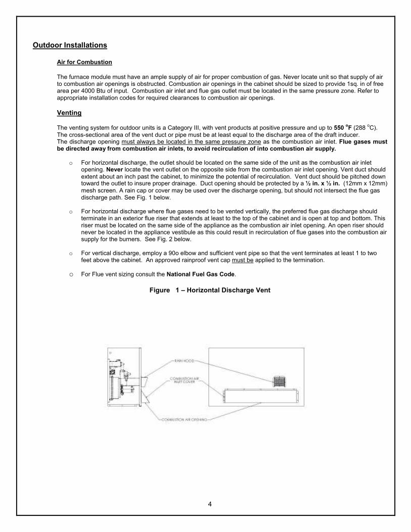
4
Outdoor Installations
Air for Combustion
The furnace module must have an ample supply of air for proper combustion of gas. Never locate unit so that supply of air to combustion air openings is obstructed. Combustion air openings in the cabinet should be sized to provide 1sq. in of free area per 4000 Btu of input. Combustion air inlet and flue gas outlet must be located in the same pressure zone. Refer to appropriate installation codes for required clearances to combustion air openings.
Venting
The venting system for outdoor units is a Category III, with vent products at positive pressure and up to 550 oF (288
oC).
The cross-sectional area of the vent duct or pipe must be at least equal to the discharge area of the draft inducer. The discharge opening must always be located in the same pressure zone as the combustion air inlet. Flue gases must be directed away from combustion air inlets, to avoid recirculation of into combustion air supply.
o For horizontal discharge, the outlet should be located on the same side of the unit as the combustion air inlet
opening. Never locate the vent outlet on the opposite side from the combustion air inlet opening. Vent duct should extent about an inch past the cabinet, to minimize the potential of recirculation. Vent duct should be pitched down toward the outlet to insure proper drainage. Duct opening should be protected by a ½ in. x ½ in. (12mm x 12mm) mesh screen. A rain cap or cover may be used over the discharge opening, but should not intersect the flue gas discharge path. See Fig. 1 below.
o For horizontal discharge where flue gases need to be vented vertically, the preferred flue gas discharge should
terminate in an exterior flue riser that extends at least to the top of the cabinet and is open at top and bottom. This riser must be located on the same side of the appliance as the combustion air inlet opening. An open riser should never be located in the appliance vestibule as this could result in recirculation of flue gases into the combustion air supply for the burners. See Fig. 2 below.
o For vertical discharge, employ a 90o elbow and sufficient vent pipe so that the vent terminates at least 1 to two
feet above the cabinet. An approved rainproof vent cap must be applied to the termination.
o For Flue vent sizing consult the National Fuel Gas Code.
Figure 1 – Horizontal Discharge Vent

5
Figure 2 – Vertical Venting- Exterior Flue Riser
Indoor Installations Air for Combustion
The furnace must be installed in a location with adequate clearances to provide for an adequate combustion air space, service and inspection, and proper clearances from combustible construction. The furnace shall be located in such a manner that it does not interfere with the circulation of air in the heated space. All fuel burning equipment must be supplied with air that enters into the combustion process and is then vented outdoors. Sufficient air must enter the appliance location to replace the air exhausted through the vent system. Do not install appliance in a confined space without providing wall openings to and from this space, if building construction is such that the normal infiltration does not provide sufficient air for combustion and venting, outside air must be introduced. Install air openings that provides a total free area in accordance with the following: 1. Air from inside the building – Opening of 1 sq. in. (645mm
2) per 1,000 Btuh (293 W) of input, but never less than 100
sq. in. (.06 m2)
2. Air from outside (ducted) – Opening of 1 sq. in. (645mm
2) Per 2,000 Btuh (586 W)
3. Air from outside (direct opening) – Opening of 1 sq. in. (645mm
2) per 4,000 Btuh (1172W)
Venting All furnace modules must be vented outside of the heated space. The furnace must be connected to a factory built chimney or vent complying with a recognized standard or a masonry or concrete chimney lined with a lining material acceptable to the authority having jurisdiction. The furnace modules will be classified in accordance with ANSI standards as follows:
o Category 1 – Non-condensing appliance with negative vent pressure
4 ft. (1.2m) Min
6 in. (152mm) diameter Min.
Open at base of tube or riser
Cabinet Draft Inducer
Relief opening and combustion air opening into vestibule must be at least 1ft.
above snow line Vent Duct

6
o Category 3 – Non-condensing appliance with positive vent pressure
Vertically Vented Furnaces – Category I (See Figure 3)
1. Use single wall or double wall (Type B) vent pipe of diameters listed in the following table for the appropriate models.
2. Maximize the height of the vertical run of vent pipe. A minimum of five (5) feet (1.5m) of vertical pipe is required. The top of the vent pipe must extend at least two (2) feet (0.61m) above the highest point on the roof. (Use Listed Type B
vent for external runs). An approved weatherproof vent cap must be installed to the vent termination.
3. Horizontal runs must not exceed 75% of the vertical height of the vent pipe, up to a maximum of ten (10) feet (3m). Horizontal runs should be pitched upward ¼” per foot (21mm/m) and should be supported at 3 foot (1m) maximum intervals.
4. Design vent pipe runs to minimize the use of elbows. Each 90o elbow is equivalent to 5 feet (1.5m) of straight vent
pipe run.
5. Vent pipe should not be run through unheated spaces. If such runs cannot be avoided, insulate vent pipe to prevent condensation inside vent pipe. Insulation should be a minimum of ½” (12.7mm) thick foil faced fiberglass, minimum 1½
# density.
6. Dampers must not be used in vent piping runs. Spillage of flue gases into the occupied space could result.
7. Vent connectors serving Category 1 heaters must not be connected into any portion of a mechanical draft system operating under positive pressure.
National Fuel Gas Code Venting Pipe requirement 75,000-149,999 Use 5-inch pipe
15,000-400,000 Use 6 Inch pipe
Figure 3
Vertical Venting – Category I
Heating Appliance
Approved Vent Cap
Type B Vent Pipe
Thimble Roof
5 Ft. Min. (1.52m)
2 Ft. Min. (0.61m)
10 Ft. Min.(3.05m)
¼ in. (6mm)
6” (152mm) Min. from pipe to ceiling
1 Ft. (305mm)
6 Ft. Min. (1.8m)
Adjacent Building
Clearance specified on Vent Pipe 10” Max. (245mm)

7
Horizontally Vented Furnaces -Category III (See Figure 4)
Pressures in Category III venting systems are positive and therefore care must be taken to avoid flue products from entering the heated space. Use only vent materials and components that are UL listed and approved for Category III venting systems. WARNING: Do not use Type B vent within a building on horizontally vented units.
All vent pipe joints must be sealed to prevent leakage into the heated space. Follow instruction provided with approved venting materials used. The proper vent pipe diameter must be used, to insure proper venting of combustion products, as follows:
• Input ratings of 150,000 Btuh (43,960 W) to 400,000 Btuh (117228 W) - 6 in. diameter (152mm)
• Input ratings of 75,000 Btuh (21,980 W) to 149,999 Btuh (43,958 W) – 5 in. diameter (126mm)
The total equivalent length of vent pipe must not exceed 50 ft. (15.25m). Equivalent length is the total length of straight sections, plus 5 ft. (1.52m) for each 90o elbow and 2.5 ft (0.76m) for each 45o elbow. The vent system must also be installed to prevent collection of condensate. Pitch horizontal pipe runs downward ¼ in. per foot (21mm per meter) toward the outlet to permit condensate drainage. Insulate vent pipe exposed to cold air or routed through unheated areas. Insulate vent pipe runs longer than 10 ft. (3m). Insulation should be a minimum of ½ in. (12mm) thick foil faced fiberglass, 1 ½ lb density. Maintain 6in. (152mm) clearance between vent pipe and combustible materials. An approved Breidert Type L, Field Starkap or equivalent vent cap must be provided. Vent cap inlet diameter must be same as the required vent pipe diameter. The vent terminal must be at least 12 in. (305mm) from the exterior wall that it passes through to prevent degradation of building material by flue gases. The vent terminal must be located at least 1 ft. (305mm) above grade, or in snow areas, at least 3 ft. (1m) above snow line to prevent blockage. Additionally, the vent terminal must be installed with a minimum horizontal clearance of 4 ft. (1.2m) from electric meters, gas meters, regulators or relief equipment.
Through the wall vents shall not terminate over public walkways, or over an area where condensate or vapor could create a nuisance or hazard. Provide Vent termination clearances to building or structure features as follows:
Structure Minimum Clearance Door, Window or gravity inlet 4 ft. (1.2 m) below 4 ft. (1.2 m) horizontally 1 ft. (305 mm) above Forced air inlet within 10 ft. (3m) 3 ft. (.91 m) above Adjoining building or parapet 6 ft. (1.8 m) Adjacent public walkways 7 ft. (2.1 m) above grade
EACH APPLIANCE MUST HAVE IT’S OWN INDIVIDUAL VENT PIPE AND TERMINAL. Do not connect vent system from horizontally vented units to other vent systems or a chimney.

8
Figure 4
Horizontal Venting – Category III
Separated Combustion Systems
HM duct furnace modules may be applied to appliances for operation in separated combustion systems. The module must be mounted with the burner section in a reasonably airtight vestibule compartment, as these systems provide combustion air from outside the heated space and vent the products of combustion outdoors. No air openings are to be provided in the vestibule access door or panel and sealing grommets or gaskets should be provided for gas and electrical entry points into the vestibule to provide a reasonably airtight seal.
1.) A suitable airtight gasket on the vestibule door or access panel. 2.) An observation window in the door to permit observation of ignition and main burner flame during operation and
servicing. 3.) A door or panel interlock switch to insure that door or panel is closed or in place during operation. 4.) Openings into the vestibule space for attachment of inlet air supply pipe and vent pipe, sized for the Btuh (W) input
rating. 5.) Approved vent terminals on both the supply air inlet and flue gas exhaust. NOTE: The inlet and outlet terminals
must be located in the same pressure zone to provide for safe appliance operation. 6.) Instructions covering installation and operation for the separated combustion system must be included in the appliance
manufacturer’s Installation and Operation Manual.
Proper installation of air inlet and flue gas exhaust piping are essential to proper operation of the appliance. Inlet air pipe must be same size as vent pipe based on input ratings. See Figures 5 and 6 for recommended installation.
5 ft. (1.52m) Min. 50 ft. (15.25 m) Max. Equivalent Length
Condensate Drain With trap – if required By local codes
1ft. (305mm) Min.
Approved Vent Terminal
3 ft. (.91m) Min. above highest snowfall
2” (51mm) clearance Thimble with
Fiberglass insulation (2”)
Heating Appliance

9
Figure 6 Separated Combustion-Horizontal Venting
Exhaust
Combustion Air Inlet
18 in. (0.46m) Min. * (See Note)
Exhaust Vent
Approved Vent Caps
18 in. (0.46m) Min.
Tee with Drip Leg and Cleanout Cap
12 in. (0.3m) Min.
2.5 ft. (0.75m) Min.
6 ft. (1.8m) Min. to Wall or Adjoining
Building
Heating Appliance
* Provide sufficient height to exceed expected snow depth
5 ft. (1.5m) Min. 25 ft. (15.2m) Max. Equivalent Length
Pitch pipes down ¼ in./ ft. (21mm / m) Toward terminal caps to allow for
Condensate drainage
12 in. (0.3m)
Building Overhang
3 ft. (0.9m) Min.
6ft. (1.8m) Min.
24 in. (0.6m)
Adjacent Building
3 ft. (0.9m) Min. Above Grade
Size by expected Snow depth
Figure 5 Separated Combustion -Vertical Venting

10
Gas Piping
1. All gas piping shall conform with local codes and ordinances, or in the absences of local codes with the National Fuel Gas Code or ANSI Z223.1. In Canada, installation must be in accordance with CAN/CGA- B149.1 for Natural gas and B149.2 for Propane Gas.
2. A manual gas shut-off valve must be installed immediately adjacent to the point where the gas supply enters the cabinet. The appliance must be isolated for the gas supply system be closing its individual manual shut-off valve during any pressure testing of the gas supply piping system at test pressures equal to or less than ½ psi. Always use clean scale free pipe and malleable iron fittings, remove all cutting and threading debris prior to connecting pipes. Firmly support the gas piping so that it cannot be dislodged from its installed position.
3. Gas piping must be sized for the total BTU input of the appliance. Refer to the unit rating plate for total input. 4. Regulators used must be sized for the total BTU input of the unit. 5. For the unit to operate properly, the inlet gas pressure must be maintained at 5.0” wc for Natural gas and
11.0” wc for propane. Maximum inlet pressure must not exceed 13.0” wc to prevent damage to the gas valve. 6. A 1/8” NPT tap is provided on the of the gas valve to the heater. A fitting suitable of connection to the
pressure gauge capable of measuring gas pressure should be connected to each heater. Check pressures when with all the units are operating at the same time.
7. A drip leg shall be provided at any point in the line of pipe where condensate and sediment could collect.
Operating and Safety instruction
1. When operating this unit for the first time, it is important to leak test all gas piping and fix any leaks before turning the unit on.
2. Do not attempt to operate unit, if there is indication that any part or control has been under water. Any control or component that has been under water must be replaced prior to start up.
Start-up
1. Turn thermostat or temperature controller to the lowest setting 2. Turn off gas supply at the manual shut-off valve 3. Turn off electrical power at the disconnect switch 4. Turn gas valve to off position at the control Knob. 5. Install a manometer or a gauge in the manifold tapped fitting. 6. Turn the gas valve control knob to On position 7. Turn gas supply to on position. 8. Turn electrical power on 9. Set thermostat to call for heat at the highest setting 10. LED light at the ignition will light 11. Induced draft blower will run for 30 second pre-purge period 12. At the end of the pre-purge period the spark igniter and the gas valve will be energized. 13. Burners should ignite. 14. If the unit fails to ignite, see trouble shooting guide inside this instructions,

11
Manifold Pressure Adjustment
• The manifold pressure for high fire second stage should be at 3.5”wc, if it needs adjustment adjust the HI Regulator on the two stage gas valve. (See Figure A).
• The manifold pressure for Low Fire First Stage should be set at 1.2”wc, if it needs adjustment adjust the LO Regulator on the two stage gas valve. (See Figure A).
Figure A – Honeywell two Stage Gas Valve
Maintenance It is recommended that an annual inspection of the heater by a qualified service personal. The condition of the burners, heat exchanger, induced draft blower, venting system and wirings. Check for any signs of deterioration, vent blockage, any signs of flame rollout or water damage. Any sign of damaged or deteriorated parts should be replaced before the unit is put back into service.
1. Turn off all electrical power before inspection and servicing 2. Check Heat Exchanger for Cracks and blockage. 3. Check and clean burners and carryover from dirt, rust and blockage by wasp nests. 4. Check venting system for blockage by animals and wasps. 5. Check the piping for any possible leaks.
Hi Pressure Adjustment
LOW Pressure Adjustment
Inlet Gas Pressure Tap
OFF/ON turn Knob

12
Utec 1016-xxx Direct Spark Ignition Control
Sequence of Operation
1. Thermostat closes on call for heat providing 24 VAC to Ignition Control 2. Draft Inducer is energized (@ line voltage) 3. Air Switch closes initiating 30 second pre-purge. 4. At end of pre-purge period, Spark and Gas Valve are energized for up to a 5 second ignition trial. 5. Burners ignite and carryover. 6. Flame is detected by flame sensor, and control operates in steady state heating condition. 7. Unit continues in operation until the thermostat is satisfied. 8. Thermostat opens interrupting power to control and shutting off unit. 9. If ignition is not achieved within 5 seconds, the gas valve is shut off; the inducer keeps running for an inter-
purge period. Additional ignition trials follow the specified sequence. If all trials (3) for ignition have occurred without proper ignition and flame detection, the control locks out.
10. Control may be brought out of lockout by cycling the thermostat or power off for a minimum of 5 seconds. 11. If ignition is not achieved within 5 seconds, the gas valve is shut off, and the inducer keeps running for an
inter-purge period. Additional ignition trials follow the specified sequence. If all trials (3) for ignition have occurred without proper ignition and flame detection, the control locks out. (To restart refer to Item 10)
12. If flame is lost once it has been established, the control will shut off the gas supply within 0.8 second and enter the inter-purge period. Control will initiate up to 3 additional trials per normal operation sequence. (To restart refer to Item 10)
13. If flame sensor indicates presence of flame during purge period, when no flame should be present, the inducer will remain energized but the gas valve off until the cause of the “false flame is removed.
14. If the air pressure switch is closed when the inducer is energized, or does not close after the inducer is energized, the control will wait one minute for the sir switch to open or close and then lock out. (To restart refer to Item 10)
15. If the control detects power to the gas valve when it should be off, or not powered when it should be on, the control will go into lockout with all outputs off. (To restart refer to 10)
NOTE: Refer to control “ Flash Code Key” if control is provided with LED indicator light.
LED Flash Code Key
On – Steady Control operation normal 1 Flash Open Pressure switch, limit switch or flame rollout switch 2 Flashes Pressure switch stuck closed 3 Flashes Ignition / flame sense failure 4 Flashes Repeated flame losses 5 Flashes Internal control fault

13
Trouble shooting guide for UTEC 1016-xxx Ignition Board
LED Code System Description Actions
Steady On Normal LED is Lit 24VAC is applied to the control
1.) Check 120V is supplied to unit and transformer
LED off Lockout LED is OFF
2.) Check to see if 24V is coming out of secondary side of transformer, if not change transformer
1.) Check pressure hose connection between the draft inducer and pressure switch.
2.) Check rollout switch manual reset to see if tripped
3.) Check for open high limit
1 Flash Lockout Open Pressure switch with induced draft blower energized
4.) Replace pressure switch
1.) Check wiring between PS1 & PS2 on the ignition controls for proper connection
2.) Check pressure switch contacts operations
3.) If pressure switch are closed shut replace pressure switch.
2 Flashes Lockout Pressure switch closed when induced draft blower is off.
1.) Verify gas supply available
2.) Verify the Gas valve is working properly and manifold pressure is adequate
3.) Check the spark igniter is cracked or dirty
4.) Check to see flame sensor wiring is good
3 Flashes Lockout Ignition Lockout from too many trials
5.) Check to see if the flame sensor is grounded to the panels
1.) Check Pressure switch hose for leaks or poor connection
2.) Check pressure switch hose for condensate in line
3.) Check pressure tap in the combustion blower for dirt blockage
4 Flashes Lockout Ignition Lockout form to many flame losses within a single call for heat
3.) Check the induced draft blower
5 Flashes Lockout Control hardware fault detected 1.) Change ignition Control board.

14
Sequence of Operation for 1171-63 Utec two-stage board When the control is in stand by mode the diagnostic red LED will be flashing a heartbeat and is continually monitoring the thermostat input and safety circuit. Call for heat:
1- On a call for first stage heat “W1” and “R” closes allowing 24vac to flow to W1 circuit. The control board than checks to see if the pressure switches are open. If either pressure switch is closed, the control flashes “3” on the LED and waits indefinitely for it to open. When the pressure switch is sensed as open, the control begins pressure switch proving period.
2- The Induced Draft blower is energized on High speed and control waits for the pressure switch to close. 3- When the pressure switch closes, a 30 second pre-purge period begins. 4- At the end of the pre-purge period, the spark igniter is energized and then the 2
nd stage gas valve high fire is
energized. 5- Once the flame is established and detected by the flame sensor, the spark igniter is de-energized and all the
burners should be light. 6- The unit should stay on second stage fire for 120 seconds warm up period regardless what the thermostat is
call for. 7- After this warm up period, the unit will re-act to what thermostat is call for. If the thermostat is calling for first
stage low fire stage, than high stage on the gas valve and on inducer is de-energized and low stage on valve and inducer energized.
8- When the thermostat is satisfied the gas valve is immediately de-energized and a 30 second post purge period starts.
LED Faults and operation failures:
Heartbeat All conditions are normal 2 Flashes Pressure Switch open with inducer on 3 Flashes Pressure Switch closed with inducer off 4 Flashes Lockout from too many failed ignition tries 5 Flashes Lockout from too many flame losses 6 Flashes High temperature switch open 7 Flashes Rollout Switch open 8 Flashes Flame present with gas off 9 Flashes Exceeded max limit trips in one call for heat (5)
1. If the flame is lost during a call for heat the control de-energizes the gas valve and counts the flame loss. If the
burner fails to light or prove flame a total of three times the control will go into a one hour Lockout period. 2. At any time the high temperature limit switch opens the control will run the inducer on high speed, de-energize
the gas valve and Flash “6” on the LED. When the high limit switch closes, the control will restart the ignition sequence again.
3. If the flame is sensed for longer than 2.0 seconds during when the gas valve should be closed, the control will enter lockout. The control will turn on the inducer blower, while the flame is present.
4. If the rollout switch opens during normal operation, the control will run the inducer on high speed for the post-purge period, immediately de-energizes the gas valve and flash “7” on the LED.
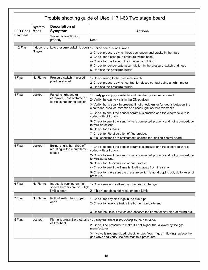
15
Trouble shooting guide of Utec 1171-63 Two stage board
LED Code System Mode
Description of Symptom Actions
Heartbeat
System is functioning properly None
1- Failed combustion Blower
2- Check pressure switch hose connection and cracks in the hose
3- Check for blockage in pressure switch hose
4- Check for blockage in the inducer barb fitting
5- Check for condensate accumulation in the pressure switch and hose
2 Flash Inducer on, No gas
Low pressure switch is open
6- Replace the pressure switch.
1- Check wiring to the pressure switch
2- Check pressure switch contact for closed contact using an ohm meter
3 Flash No Flame Pressure switch In closed position at start
3- Replace the pressure switch.
1. Verify gas supply available and manifold pressure is correct
2- Verify the gas valve is in the ON position
3- Verify that a spark in present, if not check igniter for debris between the electrodes, cracked ceramic and check ignition wire for cracks.
4- Check to see if the sensor ceramic is cracked or if the electrode wire is coded with dirt or oils.
5- Check to see if the senor wire is connected properly and not grounded, do to wire abrasions.
6- Check for air leaks
7- Check for Re-circulation of flue product
4 Flash Lockout Failed to light and or carryover, Loss of flame or flame signal during ignition.
8- If all conditions are satisfactory, change the ignition control board.
1- Check to see if the sensor ceramic is cracked or if the electrode wire is coded with dirt or oils.
2- Check to see if the senor wire is connected properly and not grounded, do to wire abrasions.
3- Check for Re-circulation of flue product
4- Check to see if the flame is floating away from the senor
5 Flash Lockout Burners light than drop off resulting in too many flame losses
5- Check to make sure the pressure switch is not dropping out, do to loses of pressure.
1- Check rise and airflow over the heat exchanger 6 Flash No Flame Inducer is running on high speed, burners ore off. High limit is open 2- If high limit does not reset, change Limit.
1- Check for any blockage in the flue pipe
2- Check for leakage inside the burner compartment
7 Flash No Flame Rollout switch has tripped open
3- Reset the Rollout switch and observe the flame for any sign of rolling out.
1- Verify that there is no voltage to the gas valve
2- Check line pressure to make it's not higher that allowed by the gas manufacturer
8 Flash Lockout Flame is present without any call for heat
3- If valve is not energized, check for gas flow. If gas in flowing replace the gas valve and verify line and manifold pressures.

16
MD - Sequence of Operation –Full Modulation
UT 1016-427 Direct Ignition Control, TR1 Timer and SC30 Modulating Control
16. Thermostat closes on call for heat. 17. 24 VAC to is supplied to Ignition Control terminal “W” through the thermostat. 18. The ignition control will verify the pressure switch is open and limits are in closed positions before energizing the
combustion blower. 19. Draft Inducer is than energized at high speed. 20. The pressure switch closes, and a 30 second pre-purge period begins. 21. At end of pre-purge period, the spark igniter is energized and the Gas Valve is powered at high fire for a 5-second
ignition trial. 22. At the end of the Ignition trial period, TR1 control is powered (SR LED Lit) and begins a 90 second warm-up period
while maintaining the combustion blower at high speed (FR LED lit). The SC30 will than power the modulating valve at high fire for the duration of the warm-up period.
23. Burners ignite and cross over, once Flame is detected by flame sensor, the spark igniter is shut-off, gas valve and combustion blower stay energized.
24. When the warm–up period expires, TR1 defaults the gas valve to low fire and the combustion blower to low speed and returns control of the operating mode to the building temperature controller. The SR LED turns off and the MR LED is lit.
25. If the building controller is providing an analog signal between 1.0 and 5.3 VDC to the SC30 control, the system will continue to operate at low fire and low speed combustion blower. The modulating valve will be powered proportional to the input voltage signal from the controller, and will open or close changing the gas manifold pressure. Manifold pressure will vary from .40 to 1.2” w.c. .
26. If the signal increases above 5.3 VDC, the combustion blower switches to high speed (FR LED lit) and high fire 2nd
stage gas valves is energized (CR LED lit). The manifold pressure will vary from 1.4 to 3.5”wc. 27. Operation will continue in High fire mode until the signal from the building management controller drops to below
4.7VDC. At this point the SC30 de-energizes the 2nd stage gas valve and the combustion blower switches to low
speed. 28. When the building thermostat is satisfied and the demand for heat ends, the gas valve is de-energized immediately the
combustion blower is energized on high speed for 30-second post-purge period. 29. The Ignition control is capable of three retrials for ignitions if the above sequence is interrupted at any point.
Operational failures during a call for heat result in “lockout” of the ignition control. The control will reset itself one hour after a lockout occurs and initiate a new trial for ignition sequence. The control may be also be reset manually by cycling the thermostat or power off for a minimum of 5 seconds. 30. If air pressure switch does not close after the inducer is energized or if limit or rollout switch (es) are open, the control
will wait one minute for the switch to close and then lock out. (1 Flash) 31. If air pressure switch is closed when the inducer is energized, the control will wait one minute for the switch to open
and then close or lock out will occur. (2 Flashes) 32. If flame sensor indicates presence of flame during purge period, when no flame should be present, the inducer will
remain energized but the gas valve off until the cause of the “false flame” is removed. (5 flashes) 33. If ignition is not achieved within 5 seconds, the gas valve is shut off; the inducer keeps running for an inter-purge
period of 60 seconds. Additional ignition trials follow the specified sequence. If all trials (3) for ignition have occurred without proper ignition and flame detection, the control will lockout. (3 Flashes)
34. If flame is lost once it has been established, the control will shut off the gas supply within 0.8 second and enter the inter-purge period. Control will initiate up to 3 ignition trials per normal operation sequence. (4 Flashes)
35. If the control detects power to the gas valve when it should be off, or not powered when it should be on, the control will go into lockout with all outputs off. (5 flashes)
LED Flash Code Key (UT1016-400 Series)
On – Steady Control operation normal 1 Flash Open Pressure switch, limit switch or flame rollout switch 2 Flashes Pressure switch stuck closed 3 Flashes Ignition / flame sense failure 4 Flashes Repeated flame losses 5 Flashes Internal control fault

17
Table 1 - HMA, HMB Series Ratings
Input Rate Tube Depth
Min. Duct Opening
Min. Duct Area
Min. Clearances to duct from tube. Output Temp Rise
Air Flow @ Min.
Duct Opening
Min. Max. Min.
Depth Height / Width Top Bottom Rear Min. Max. Min. Max.
Btuh in. in. in. in. ft. 2 in. in. in.
Btuh
oF
oF cfm cfm
Model No.
W mm mm mm mm m2 mm mm mm W
oC
oC m
3/s m
3/s
HMA Series - Cross flow-Hoizontal or Vertical
400,000 31 9.9 320,000 3292 14815
HMA-400 117,228 787 0.92 93782 1.55 6.99
350,000 31 9.9 280,000 2881 12963
HMA350 102,575 787 0.92 82060 1.36 6.12
350,000 27.75 8.86 280,000 2881 12963
HMA350 102,575 705 0.82 82060 1.36 6.12
300,000 24.5 7.83 240,000 2469 11111
HMA300 87,921
42 48 46
622 0.73
1.75 2.75 2
70337
20 90
1.16 5.24
250,000 24.5 7.83 200,000 2058 9259
HMA250 73,268 622 0.73 58614 0.97 4.37
250,000 21.25 6.79 200,000 2058 9259
HMA250 73,268 540 0.63 58614 0.97 4.37
200,000 18 5.75 160,000 1646 7407
HMA200 58,614 457 0.53 46891 0.78 3.5
150,000 18 5.75 120,000 1235 5556
HMA150 43,961
1067 1321 1168
457 0.53
44 70 51
35168
11 50
0.58 2.62
HMB Series - Crossflow- Horizontal or Vertical
400,000 33.5 18.03 320,000 3292 14815
HMB400 117,228 851 1.67 93782 1.55 6.99
375,000 33.5 17.45 300,000 3086 13889
HMB375 109,901 851 1.62 87921 1.46 6.55
350,000 30.25 16.28 280,000 2881 12963
HMB350 102,575 768 1.51 82060 1.36 6.11
325,000 30.25 14.49 260,000 2675 12037
HMB-325 95,248 768 1.35 76198 1.22 5.5
300,000 27 12.94 240,000 2469 11111
HMB-300 87,921
75.5 75.5 77.5
686 1.2
1.75 2.75 2
70337
20 90
1.16 5.24
275,000 27 12.94 224,000 2305 10370
HMB-275 82,060 686 1.2 65648 1.09 4.89
250,000 23.75 11.38 200,000 2058 9259
HMB-250 73,268 603 1.06 58614 0.97 4.37
225,000 23.75 11.38 180,000 1852 8333
HMB-225 65,941 603 1.06 52753 0.87 3.93
200,000 20.5 9.82 160,000 1646 7407
HMA200 58,614 521 0.91 46891 0.78 3.49
175,000 20.5 9.82 140,000 1440 6481
HMB175 51,287
1918 1918 1969
521 0.91
44 70 51
41,030
11 50
0.7 3.14

18
Table 2 – HMG and HMH Series Ratings
Input Rate Tube Depth Min. Duct Opening
Duct Area Min. Clearances to duct from tube.
Output Temp Rise Air Flow @ Min. Duct Opening
Min. Max. Min. Depth
Width Min. Top Bottom Rear Min. Max. Min. Max.
Btuh in. in. in. in. ft. 2 in. in. in.
Btuh
oF
oF cfm cfm
Model No. / (No. Tubes)
W mm mm mm mm m2 mm mm mm W
oC
oC m
3/s m
3/s
HMG Series - Crossflow Horizontal and Vertical
400,000 26 34 31 49 10.55 320,000 3704 14815 HMG400 (15)
117,228 635 864 787 1245 0.98 93782 1.75 6.99
375,000 49 9.53 300,000 3472 13889 HMG375 (15)
109,901 1245 0.89 87921 1.64 6.55
350,000 46.25 8.99 280,000 3241 12963 HMG350 (14)
102,575 1175 0.84 82060 1.53 6.11
325,000 46.25 8.99 260,000 3009 12037 HMG325 (14)
95,248
26 34 28
1175 0.84
1 1 2
76198
20 80
1.42 5.68
300,000 40.75 8.77 240,000 2778 11111 HMG300 (12)
87,921 1035 0.81 70337 1.31 5.24
275,000 40.75 8.77 220,000 2546 10185 HMG275 (12)
80,594 1035 0.81 64475 1.2 4.8
250,000 35.25 7.59 200,000 2315 9259 HMG250 (10)
73,268 895 0.7 58614 1.09 4.37
225,000 35.25 7.59 180,000 2083 8333 HMG225 (10)
65,941
660 864 711
895 0.7
25 25 51
52753
11 44
0.98 3.93
200,000 29.75 5.78 160,000 1852 7407 HMG200 (8)
58,614 756 0.54 46891 0.87 3.49
175,000 27 5.25 140,000 1620 6481 HMG175 (7)
51,287 686 0.49 41030 0.76 3.06
150,000 24.25 4.72 120,000 1389 5556 HMG150 (6)
43,961
26 34 28
616 0.44
1 1 2
35168
20 80
0.66 2.62
125,000 21.5 4.18 100,000 1157 4630 HMG125 (5)
36,634 546 0.39 29307 0.55 2.18
100,000 18.75 3.65 80,000 926 3704 HMG100 (4)
29,307 476 0.34 23446 0.44 1.75
75,000 16 3.11 60,000 694 2778 HMG075 (3)
21,980
660 864 711
406 0.29
25 25 51
17584
11 44
0.33 1.31
HMH Series - Crossflow Horizontal and Vertical
240,000 23.25 7.59 192,000 1975 8889 HMH 240 (8)
70,337 591 0.7 56269 1.4 4.19
210,000 20.25 6.61 168,000 1728 7778 HMH210 (7)
61,545 514 0.61 49236 1.22 3.67
180,000
45 56 47
17.25 5.63
1.75 2.75 2
144,000
20 90
1481 6667 HMH180 (6)
52,753 438 0.52 42202 1.05 3.14
150,000 14.25 4.65 120,000 1235 5556 HMH150 (5)
43,961 362 0.43 35168 0.87 2.62
120,000 11.25 3.67 96,000 988 4444 HMH120 (4)
35,168
1143 1321 1194
286 0.34
44 70 51
28135
11 33
0.7 2.1

19
Table 3 – HMC, HMD, HME and HMF Ratings
Tube Depth Min. Duct Opening
Min. Duct Area
Min. Clearances to duct from tube. Temp Rise
Air Flow @ Min. Duct Opening Input
Rate
Min. Max. Min. Depth Height / Width Top Bottom Rear Min. Max. Min. Max.
Btuh in. in. in. in. ft. 2 in. in. in.
Output BTUH
oF
oF cfm cfm
Model No.
W mm mm mm mm m2 mm mm mm W
oC
oC m
3/s m
3/s
HMC Series - Parallel Flow
300,000 31 8.61 240,000 2469 11111
HMC300 87,921 787 0.8 70337 1.16 5.24
265,000 28 7.78 212,000 2181 9815
HMC265 77,664
38 40 40
711 0.72
1.5 2.5 2
62131
20 90
1.03 4.63
230,000 25 6.94 184,000 1893 8519
HMC230 67,406 635 0.65 53925 0.89 4.02
200,000 22 6.11 160,000 1646 7407
HMC200 58,614
965 1016 1016
559 0.57
38 64 51
46891
11 50
0.78 3.49
HMD Series - Parallel Flow
200,000 28 5.98 160,000 1646 7407
HMD200 58,614 711 0.56 46891 0.78 3.49
175,000 25 5.34 140,000 1440 6481
HMD175 51,287 635 0.5 41030 0.68 3.06
150,000 22 4.7 120,000 1235 5556
HMD150 43,961
28.75 36 30.75
559 0.44
1.75 2.75 2
35168
20 90
0.58 2.62
125,000 19 4.06 100,000 1029 4630
HMD125 36,634 483 0.38 29307 0.49 2.18
100,000 16 3.42 80,000 823 3704
HMD100 29,307 406 0.32 23446 0.39 1.75
75,000 13 2.78 60,000 617 2778
HMD075 21,980
730 914 781
330 0.26
44 70 51
17584
11 50
0.29 1.31
HME Series - Parallel Flow
150,000 19.5 4.06 120,000 1235 5556
HME150 43,961 495 0.38 35168 0.58 2.62
125,000
28 36 30
16.75 3.49
1.5 2 2
100,000
20 90
1029 4630
HME125 36,634 425 0.32 29307 0.49 2.18
100,000 14 2.92 80,000 823 3704
HME100 29,307
711 914 762
356 0.27
38 51 51
23446
11 50
0.39 1.75
HMF Series - Parallel Flow
120,000 19.5 3.45 96,000 988 4444
HMF125 35,168 495 0.32 28135 0.47 2.1
100,000
23.5 28 25.5
16.75 2.97
1.5 2 2
80,000
20 90
823 3704
HMF100 29,307 425 0.28 23446 0.39 1.75
80,000 14 2.48 64,000 658 2963
HMF080 23,446
597 711 648
356 0.23
38 51 51
18756
11 50
0.31 1.4
Notes
It is recommended that applications using 50% or more outside air must use stainless steel heat exchanger do to possible condensate

20

J3E 1Z9
NO.
2121, Rue NobelSainte Julie Québec
Tel : (438) 338-1101Fax : (450) 649-8756
DATE : FILE. :
WIRING DIAGRAM
01 01/Folio no. :
TA350SM + 3X TA350S1
1A
2011-08-24 31453-16670FP
31453-16670_PO 10826 TAG 11071804
PO 10826 TAG 11071804BY
DESIGNED BY: APPROVED BY:
PROJECT:
MODEL:
UNIT:
TITLE:
DRAWING:
DATE
REVISIONS
DESCRIPTION
2011-08-24
A B C D E
01
02
03
04
05
06
07
08
09
10
11
12
13
14
15
16
17
18
19
20
21
22
23
24
25
26
27
28
29
30
31
32
33
34
35
36
37
38
39
40
41
42
TO PREVENT INDUCTION (BY OTHERS)
GROUNDED AT ONE END ONLY
REQUIRES SHIELDED WIRE
THE SHIELDED WIRE MUST BE
FIELD WIRING
FACTORY WIRING
UNIT TERMINAL
REMOTE CONTROL PANEL TERMINAL
BLANC /WHITE =WTNOIR/BLACK =BKROUGE/RED =RDBLEU/BLUE =BLVIOLET/PURPLE =VTORANGE/ORANGE =ORBRUN/BROWN =BNVERT/GREEN =GNJAUNE/YELLOW =YL
WIRES COLOURS CHART
ELECTRIC VOLTAGE / ELECTROCUTION RISKA BAD INSTALLATION CAN CAUSE MATERIEL DAMAGE,
WOUND OR EVEN DEATH.ONLY QUALIFIED PEOPLE SHOULD MAKE THE INSTALLATION AND MAINTENANCE
! DANGER:
ANY ELECTRICAL MODIFICATION MADE TO
APPROVAL CANCELS THE WARRANTY
! ATTENTION:ANY ELECTRICAL MODIFICATION MADE TO
THE APPARATUS WITHOUT NAGAS INNOVATIONAPPROVAL CANCELS THE WARRANTY
! ATTENTION:
!! NOTE :
A CONDUCTOR MUST BE USED FOR GROUNDINGAND NOT THE STEEL CONDUCT
FOR THIS TYPE OF UNIT
UNIT WIRINGS ARE COPPER ONLYFOR CONTROL DIAGRAM THE GAGE USED IS 16AWG
!! NOTE :
120 / 1 / 60
MCA : 13A
MOP : 16A
TO BECKET HM-1 (MODULATING) TO BECKET HM-2 ( 1 STAGE)
LEGEND
F1 CONTROL FUSE
PB1 POWER BLOCK
PLC1 PLC UNIT
R4 HMA 1 RUN PROOF RELAY
TO BECKET HM-3 ( 1 STAGE)TO BECKET HM-4 ( 1 STAGE)
L0
53
RD
R4
(01-21-B)
RD/BK
C
54
(BY OTHERS)55
HEATING MODULATION SIGNAL (0-10V)
56
50
51
YL
YL
BN
BL
START / STOPHEATING
DRY CONTACT 24 VAC, MAX
(BY OTHERS)
START / STOPUNIT
DRY CONTACT 120 VAC, MAX
(BY OTHERS)
HEATING ON
(DRY CONTACT)
R4
(01-34-A)
+
BL
55
-
WT
/BK
56
W
GN
57
1
3
6
7
R
OR
58
JUMPER
BY OTHERS
FIRE ALARM
(DRY CONTACT 120VAC)
L2
RD
RD
BN
BL
RD
BN
2
WT
L+
I8
Q1/1
Q1/2
Q2/1
Q2/2
Q3/1
Q3/2
Q4/1
Q4/2
M
I1
I2
I3
I4
I5
I6
I7
++
--
L1
NPLC1
BK
N
PB1
L1
L1
3
GND
11BK
BK
F115A
81
R
RD
BK
GN
RD
OR
GN
WT
82
W
GN
GN
GN
RD
RD
BK
WT
L2
2
BK
3
L1
GND
RD
71
R W
72
GN
WT
2
L2
BK
3
L1 R
RD
61
WT
W
GN
62
L2
WT
2
2
3
2
BK
L1
3

J3E 1Z9
NO.
2121, Rue NobelSainte Julie Québec
Tel : (438) 338-1101Fax : (450) 649-8756
DATE : FILE. :
WIRING DIAGRAM
01 01/Folio no. :
TA350SM + 3X TA350S1
2A
2011-08-24 31454-16670FP
31454-16670_PO 10826 TAG 11071805
PO 10826 TAG 11071805BY
DESIGNED BY: APPROVED BY:
PROJECT:
MODEL:
UNIT:
TITLE:
DRAWING:
DATE
REVISIONS
DESCRIPTION
2011-08-24
A B C D E
01
02
03
04
05
06
07
08
09
10
11
12
13
14
15
16
17
18
19
20
21
22
23
24
25
26
27
28
29
30
31
32
33
34
35
36
37
38
39
40
41
42
TO PREVENT INDUCTION (BY OTHERS)
GROUNDED AT ONE END ONLY
REQUIRES SHIELDED WIRE
THE SHIELDED WIRE MUST BE
FIELD WIRING
FACTORY WIRING
UNIT TERMINAL
REMOTE CONTROL PANEL TERMINAL
BLANC /WHITE =WTNOIR/BLACK =BKROUGE/RED =RDBLEU/BLUE =BLVIOLET/PURPLE =VTORANGE/ORANGE =ORBRUN/BROWN =BNVERT/GREEN =GNJAUNE/YELLOW =YL
WIRES COLOURS CHART
ELECTRIC VOLTAGE / ELECTROCUTION RISKA BAD INSTALLATION CAN CAUSE MATERIEL DAMAGE,
WOUND OR EVEN DEATH.ONLY QUALIFIED PEOPLE SHOULD MAKE THE INSTALLATION AND MAINTENANCE
! DANGER:
ANY ELECTRICAL MODIFICATION MADE TO
APPROVAL CANCELS THE WARRANTY
! ATTENTION:ANY ELECTRICAL MODIFICATION MADE TO
THE APPARATUS WITHOUT NAGAS INNOVATIONAPPROVAL CANCELS THE WARRANTY
! ATTENTION:
!! NOTE :
A CONDUCTOR MUST BE USED FOR GROUNDINGAND NOT THE STEEL CONDUCT
FOR THIS TYPE OF UNIT
UNIT WIRINGS ARE COPPER ONLYFOR CONTROL DIAGRAM THE GAGE USED IS 16AWG
!! NOTE :
120 / 1 / 60
MCA : 13A
MOP : 16A
TO BECKET HM-1 (MODULATING) TO BECKET HM-2 ( 1 STAGE)
LEGEND
F1 CONTROL FUSE
PB1 POWER BLOCK
PLC1 PLC UNIT
R4 HMA 1 RUN PROOF RELAY
TO BECKET HM-3 ( 1 STAGE)TO BECKET HM-4 ( 1 STAGE)
L0
53
RD
R4
(01-21-B)
RD/BK
C
54
(BY OTHERS)55
HEATING MODULATION SIGNAL (0-10V)
56
50
51
YL
YL
BN
BL
START / STOPHEATING
DRY CONTACT 24 VAC, MAX
(BY OTHERS)
START / STOPUNIT
DRY CONTACT 120 VAC, MAX
(BY OTHERS)
HEATING ON
(DRY CONTACT)
R4
(01-34-A)
+
BL
55
-
WT
/BK
56
W
GN
57
1
3
6
7
R
OR
58
JUMPER
BY OTHERS
FIRE ALARM
(DRY CONTACT 120VAC)
L2
RD
RD
BN
BL
RD
BN
2
WT
L+
I8
Q1/1
Q1/2
Q2/1
Q2/2
Q3/1
Q3/2
Q4/1
Q4/2
M
I1
I2
I3
I4
I5
I6
I7
++
--
L1
NPLC1
BK
N
PB1
L1
L1
3
GND
11BK
BK
F115A
81
R
RD
BK
GN
RD
OR
GN
WT
82
W
GN
GN
GN
RD
RD
BK
WT
L2
2
BK
3
L1
GND
RD
71
R W
72
GN
WT
2
L2
BK
3
L1 R
RD
61
WT
W
GN
62
L2
WT
2
2
3
2
BK
L1
3

Multiple unit controller
Heaters configuration
The heating system is made of one modulating heater (SM) with a 4 to 1 turndown ratio coupled
with one or more 1-stage heaters (S1). A single PLC controls all heaters independently with the
modulating heater firing at up to 4 stages and the 1-stage heaters firing at full fire.
When the call for heat increases, the PLC turns ON the modulating heater. If the needed heat
output is higher than the capacity of the heater, one single-stage heater will be turned on and
the modulating heater will be fired at 0% capacity, 50% capacity or 100% capacity. As more heat
is needed (and if more heaters are available in the system) another single-stage heater is turned
ON and the modulating heater is fired at 0%, 50% or 100% capacity.
To prevent unneeded cycling of stages and heaters, a timer is in function between stages up or
down in capacity.
The following schematic shows the number of stages and the total output depending on the
heat available.
Systems with 4 heaters (based on 400MBH heaters)
Air
Heater A1
(S1)
Heater B1
(S1)
Heater A2
(SM)
Heater B2
(S1)
Stage Input
voltage
(Vdc)
Percentage of
modulating
heater (A2)
Percentage of single-stage heaters Input
heat
(MBH)
Output
heat
(MBH)
A1 B1 B2
1 1.00 25% 0% 0% 0% 100 80
2 2.00 50% 0% 0% 0% 200 160
3 3.00 75% 0% 0% 0% 300 240
4 4.00 100% 0% 0% 0% 400 320
5 5.00 50% 100% 0% 0% 600 480
6 6.00 100% 100% 0% 0% 800 640
7 7.00 50% 100% 100% 0% 1000 800
8 8.00 100% 100% 100% 0% 1200 960
9 9.00 50% 100% 100% 100% 1400 1120
10 10.00 100% 100% 100% 100% 1600 1280

Systems with 6 heaters (based on 300MBH heaters)
Air
Heater A1
(S1)
Heater B1
(S1)
Heater A2
(SM)
Heater B2
(S1)
Heater A3
(S1)
Heater B3
(S1)
Stage Input
voltage
(Vdc)
Percentage
of
modulating
heater (A2)
Percentage of single-stage heaters Input heat
(MBH)
Output
heat (MBH)A1 A3 B1 B2 B3
1 0.71 25% 0% 0% 0% 0% 0% 75 60
2 1.43 50% 0% 0% 0% 0% 0% 150 120
3 2.14 75% 0% 0% 0% 0% 0% 225 180
4 2.86 100% 0% 0% 0% 0% 0% 300 240
5 3.57 50% 100% 0% 0% 0% 0% 450 360
6 4.29 100% 100% 0% 0% 0% 0% 600 480
7 5 50% 100% 100% 0% 0% 0% 750 600
8 5.71 100% 100% 100% 0% 0% 0% 900 720
9 6.43 50% 100% 100% 100% 0% 0% 1050 840
10 7.14 100% 100% 100% 100% 0% 0% 1200 960
11 7.86 50% 100% 100% 100% 100% 0% 1350 1080
12 8.57 100% 100% 100% 100% 100% 0% 1500 1200
13 9.29 50% 100% 100% 100% 100% 100% 1650 1320
14 10.00 100% 100% 100% 100% 100% 100% 1800 1440

PLC display and run mode
The PLC has a display that shows its status.

To start the program, the PLC has to be in "RUN" mode. To activate the run mode, do the
following:

________________________________________________
Issue Date : 2011-10-06
www.serescodehumidifiers.com Supersedes : 2011-09-20
Seresco Technologies Inc. has a policy of continuous product and product data improvement and reserves the right to change
design and specifications at any time without prior notification. Only qualified technicians working within their area of
competence should perform the installation and maintenance of equipment referred to in this literature.