Embed Size (px)
Citation preview
High Inlet Air Temperature
Air Dryers
Installation & Operation
Maintenance Manual
Model
CHI 20 CHI 25 CHI 40 CHI 55 CHI 75 CHI 110
CHIIOM 01-02 Rev. REL
Model Number: Serial Number: FILL IN COMPLETELY AT INSTALLATION
Coaire Technologies Corporation 12226 Coast Drive, Whittier, CA 90601 ◊ TEL.(562)463-3935 ◊ (562)463-4928
website: www.coaire.com ■ e-mail: [email protected]/[email protected]
Printed in U.S.A. FORM CM-AD01
FEB. 2002
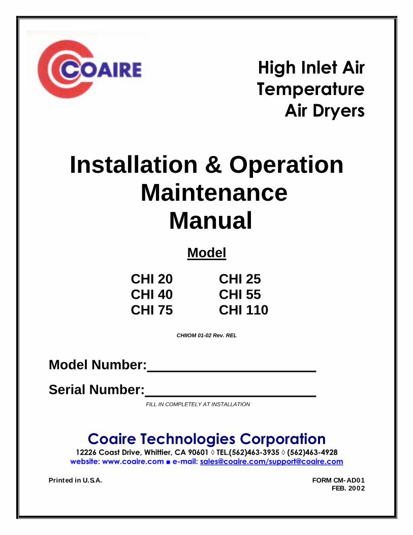
STATEMENT OF WARRANTY TERMS & CONDITIONS COAIRE’s refrigerated air dryers are warranted to be free of defects in materials and workmanship under proper use, installation, and application. This warranty shall be for a period of 15 months from date of shipment from our factory or other stocking facilities or 12 months from date of installation. Proof of installation date will be required. All dryers outside the U.S. and Canada carry a parts only warranty. ALL FREIGHT DAMAGE CLAIMS ARE NOT THE RESPONSIBILITY OF THE MANUFACTURER AND ARE NOT COVERED UNDER WARRANTY AS ALL PRODUCTS ARE SHIPPED F.O.B. SHIPPER.
PLEASE DIRECT ALL FREIGHT CLAIMS TO THE SHIPPER IN QUESTION.
MAINTENANCE AND ADJUSTMENTS
ADJUSTMENTS TO THE HOT GAS AND MAINTENANCE OF FLOAT AND AUTOMATIC DRAINS AND CONDENSER COILS ARE CONSIDERED TO BE ROUTINE MAINTENANCE AND THEREFORE NON-WARRANTABLE ITEMS AND ARE THE SOLE RESPONSIBILITY OF THE END USER. CONSULT THE INSTALLATION, OPERATION AND MAINTENANCE MANUAL FOR THE ADJUSTMENT AND MAINTENANCE PROCEDURES.
This warranty does not apply to any unit damaged by accident, modification, misuse, negligence, or misapplication. Damage to heat exchangers by exposure to ammonia, any other corrosive substance or sub-freezing environment will be considered misuse.
Any refrigerated dryer part or material found defective will be repaired, replaced or refunded, at the sellers option free of charge, provided that COAIRE is notified within the above stated warranty period. All returns of allegedly defective equipment must have prior written authorization. Said authorization may be obtained through our refrigerated dryer service department. All refrigerated dryers, parts, materials must be returned freight prepaid to the Manufacturer’s factory within 30 days of return authorization date. Any shipment returned to the factory collect will be refused.
If an item is found to be warrantable, the repaired item or replacement will be returned normal ground freight prepaid within the continental United States and Canada. Expedited shipment costs are the responsibility of the requestor.
Any replacement part or material is warranted only to the extent of the remaining warranty period of the dryer or to the extent as provided by the supplier, whichever is longer.
Identification Plate
The identification plate is located on the back of the dryer and shows all the primary data of the machine. Upon installation, fill in the table on the previous page with all the data shown on the identification plate. This data should always be referred to when calling the manufacturer or distributor.
The removal or alteration of the identification plate will void the warranty rights. DISCLAIMER
The warranty does not cover any responsibility or liability for direct or indirect damages to persons, or equipment caused by improper usage or maintenance, and is limited to manufacturing defects only. Refer to COAIRE Warranty policy manual for travel, mileage and special charge considerations. The warranty will be immediately voided if there are changes or alterations to the dryer.
WHO TO CONTACT IF YOU HAVE A WARRANTY CLAIM: COAIRE Technologies, Corporation Phone (562) 463-3935
Fax (562) 463-4928
All freight damage claims should be filed within 15 working days and should be directed to the carrier.
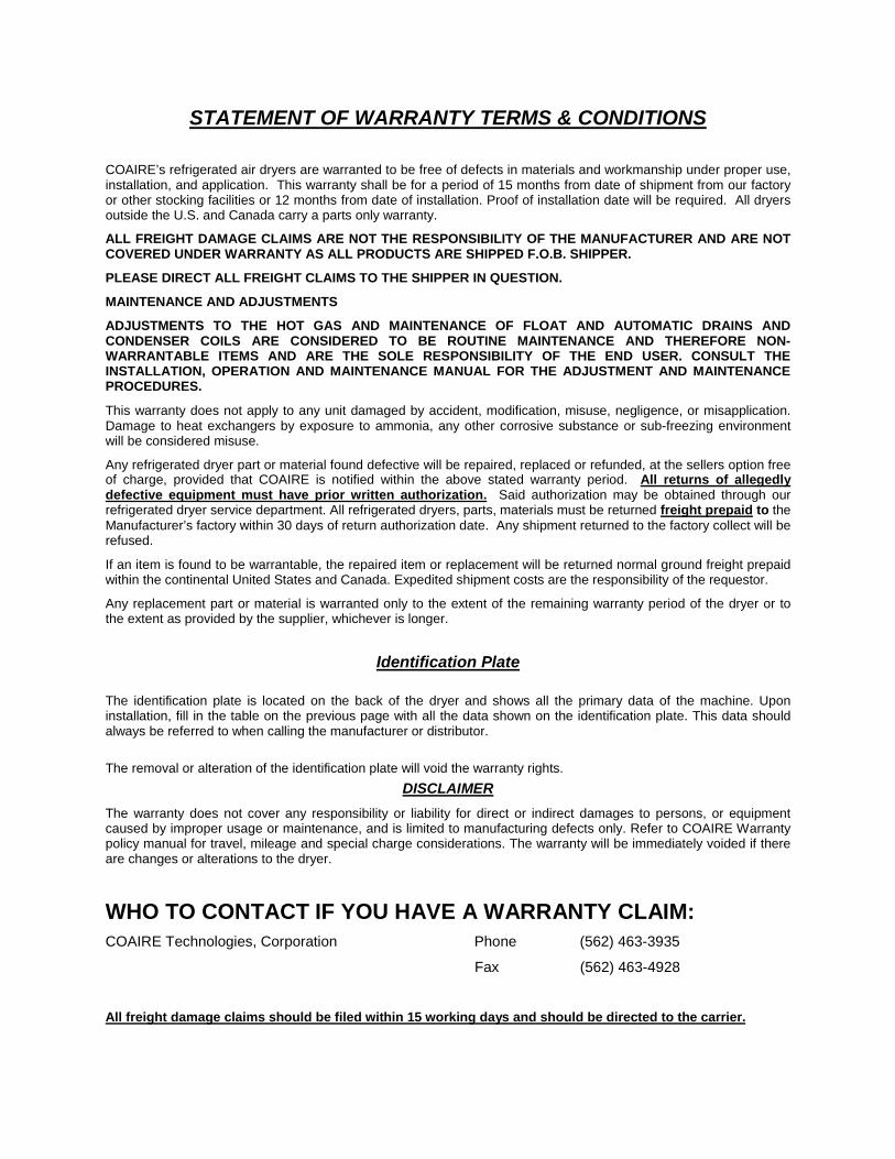
TABLE OF CONTENTS
1. SAFETY RULES 1.1 Explanation of Convention Symbols Used in This Manual 1.2 Warnings 1.3 Proper Use of the Dryer
2. INSTALLATION 2.1 Transporting the unit 2.2 Installation site 2.3 Installation layout & Correction factors 2.4 Connection to the Compressed Air System 2.5 Connection to the Main Power 2.6 Condensate Drain
3. START-UP 3.1 Preliminary Operations 3.2 Initial Start Up 3.3 Operation and Shut-down
4. TECHNICAL INFORMATION 4.1 Technical Specifications-CHI20 -CHI25 4.2 Technical Specifications-CHI40- CHI55 4.3 Technical Specifications-CHI75- CHI110
5. TECHNICAL DESCRIPTION 5.1 Control Panel 5.2 Operation 5.3 Flow diagram-CHI20 -CHI 55 5.4 Flow diagram-CHI 75 5.5 Flow diagram-CHI110 5.6 Refrigeration Compressor 5.7 Condenser unit 5.8 Filter Drier 5.9 Capillary Tube 5.10 Evaporator 5.11 Liquid separator (CHI 75-CHI110) 5.12 Hot Gas By-pass Solenoid Valve 5.13 5 micron Filter 5.14 Aftercooler 5.15 Air -Air Exchanger 5.16 Condensate Separator 5.17 Fan Pressure switch PV (CHI 110) 5.18 DMC 11 Controller 5.19 Electrical Schematic-CHI20-CHI25 5.20 Electrical Schematic-CHI40-CHI75 5.21 Electrical Schematic-CHI 110
6. MAINTENANCE, REPLACEMENT PARTS 6.1 Maintenance Schedule 6.2 Replacement Parts
7. TROUBLESHOOTING 7.1 Troubleshooting
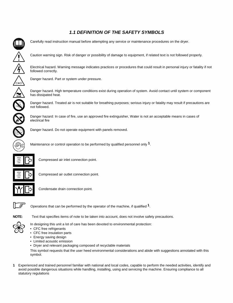
1.1 DEFINITION OF THE SAFETY SYMBOLS
Carefully read instruction manual before attempting any service or maintenance procedures on the dryer.
Caution warning sign. Risk of danger or possibility of damage to equipment, if related text is not followed properly.
Electrical hazard. Warning message indicates practices or procedures that could result in personal injury or fatality if not followed correctly.
Danger hazard. Part or system under pressure.
Danger hazard. High temperature conditions exist during operation of system. Avoid contact until system or component has dissipated heat.
Danger hazard. Treated air is not suitable for breathing purposes; serious injury or fatality may result if precautions are not followed.
Danger hazard: In case of fire, use an approved fire extinguisher, Water is not an acceptable means in cases of electrical fire
Danger hazard. Do not operate equipment with panels removed.
Maintenance or control operation to be performed by qualified personnel only 1.
ARIAAIR
LUFTAIR
Compressed air inlet connection point.
ARIAAIR
LUFTAIR
Compressed air outlet connection point.
Condensate drain connection point.
Operations that can be performed by the operator of the machine, if qualified 1.
NOTE: Text that specifies items of note to be taken into account, does not involve safety precautions.
In designing this unit a lot of care has been devoted to environmental protection: • CFC free refrigerants • CFC free insulation parts • Energy saving design • Limited acoustic emission • Dryer and relevant packaging composed of recyclable materials This symbol requests that the user heed environmental considerations and abide with suggestions annotated with this symbol.
1 Experienced and trained personnel familiar with national and local codes, capable to perform the needed activities, identify and avoid possible dangerous situations while handling, installing, using and servicing the machine. Ensuring compliance to all statutory regulations
1.2 WARNINGS
Compressed air is a highly hazardous energy source. Never work on the dryer with pressure in the system. Never point the compressed air or the condensate drain outlet hoses towards anybody. The user is responsible for the proper installation of the dryer. Failure to follow instructions given in the “Installation” chapter will void the warranty. Improper installation can create dangerous situations for personnel and/or damages to the machine could occur.
Only qualified personnel are authorized to service electrically powered devices. Before attempting maintenance, the following conditions must be satisfied : Ensure that main power is off, machine is locked out, tagged for service and power cannot be restored during service operations. Ensure that valves are shut and the air circuit is at atmospheric pressure. De-pressurize the dryer.
Warranty does not apply to any unit damaged by accident, modification, misuse, negligence or misapplication. Unauthorized alterations will immediately void the warranty.
1.3 PROPER USE OF THE DRYER
This dryer has been designed, manufactured and tested for the purpose of separating the humidity normally contained in compressed air. Any other use has to be considered improper.
The Manufacturer will not be responsible for any problem arising from improper use; the user will responsible for any resulting damage.
• Moreover, the correct use requires the adherence to the installation instructions, specifically: Voltage and frequency of the main power. • Pressure, temperature and flow-rate of the inlet air. • Ambient temperature.
This dryer is supplied tested and fully assembled. The only operation left to the user is the piping connections to the compressed air system in compliance with the instructions given in the following chapters.
The purpose of the machine is the removal of water and residual oil vapor present in compressed air. The dried air cannot be used for respiration purposes or for operations leading to direct contact with food products. This dryer is nor suitable for the treatment of dirty air or of air containing solid particles.
2.1 TRANSPORTING THE UNIT Check for visible loss or damage, if no visible damage is found place the unit near to the installation point and unpack the contents.
• Always keep the dryer in the upright vertical position. Damage to components could result if unit is laid on its side or if placed upside down.
• Store machine in a clean, dry environment, do not expose to severe weather environments.
The packaging materials are recyclable. Dispose of material in compliance with the rules and regulations in force in the destination country.
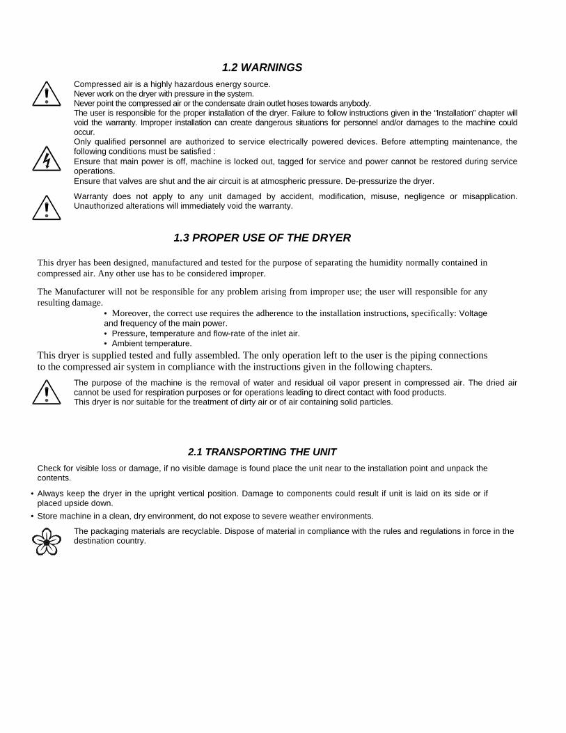
2.2 INSTALLATION SITE
Failure to install dryer in the proper ambient conditions will affect the dryer’s ability to condense refrigerant gas. This can cause higher loads on the compressor, loss of dryer efficiency and performance, overheated condenser fan motors, electrical component failure and dryer failure due to the following: compressor loss, fan motor failure and electrical component failure. Failures of this type will affect warranty considerations. Do not install dryer in an environment of corrosive chemicals, explosive gasses, poisonous gasses; steam heat, areas of high ambient conditions or extreme dust and dirt.
In case of fire, use an approved fire extinguisher, Water is not an acceptable means in cases of electrical fire.
Minimal installation requirements:
• Select a clean dry room, free from dust, and protected from atmospheric disturbances. • The supporting plate must be smooth, horizontal and able to hold the weight of the dryer. • Minimum ambient temperatures 34°F see the data plate for maximum temperature. • Allow at least 40 inches of clearance on each side of the dryer for proper ventilation and to facilitate maintenance
operations. The dryer doesn't require to be fixed to the supporting surface. Locks will be required for special installations (on brackets, hanging, etc.).
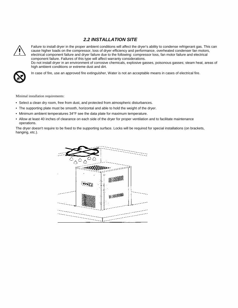
2.3 INSTALLATION LAYOUT
Type A installation is suequals the compressor Type B installation is suflow rate of the compresconditions (peak air con Correction factor for iInlet air pressure psigFactor
Correction factor for aAmbient TemperatureFactor
Correction factor for inAir Temperature °F Factor
ggested when the compressor operates at reduced intermittence and the total consumption flow rate.
ggested when the air consumption can consistently change with peak values highly exceeding the sors. The capacity of the tank must be sized in order to compensate for more demanding sumption).
nlet air pressure changes: 80 100 150 200 230
1.25 1.00 .87 .83 .80
mbient temperature changes (Air cooled only): °F 85 100 105 110
.91 1.00 1.10 1.22
let air temperature changes: 125 150 180 200 .85 .91 1.00 1.11
1 AIR COMPRESSOR 5 DRYER 2 PRE-FILTER 6 BY-PASS 3 COMPRESSED AIR TANK 7 CONDENSATE DRAIN 4 AFTERFILTER
2
7 7 7
3
4
5
6 1
2
1
7 5
6
3
7 7
4
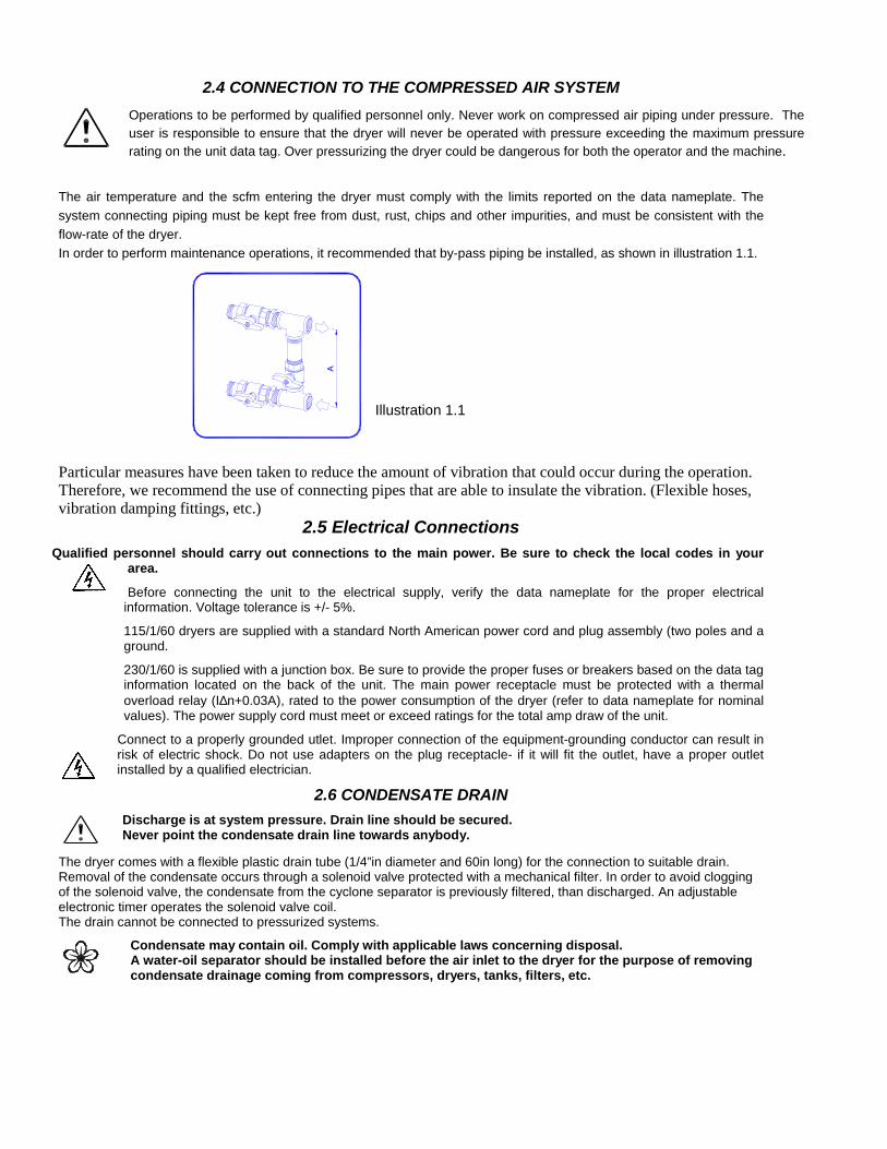
2.4 CONNECTION TO THE COMPRESSED AIR SYSTEM
Operations to be performed by qualified personnel only. Never work on compressed air piping under pressure. The user is responsible to ensure that the dryer will never be operated with pressure exceeding the maximum pressure rating on the unit data tag. Over pressurizing the dryer could be dangerous for both the operator and the machine.
The air temperature and the scfm entering the dryer must comply with the limits reported on the data nameplate. The system connecting piping must be kept free from dust, rust, chips and other impurities, and must be consistent with the flow-rate of the dryer. In order to perform maintenance operations, it recommended that by-pass piping be installed, as shown in illustration 1.1.
Illustration 1.1
Particular measures have been taken to reduce the amount of vibration that could occur during the operation. Therefore, we recommend the use of connecting pipes that are able to insulate the vibration. (Flexible hoses, vibration damping fittings, etc.)
2.5 Electrical Connections Qualified personnel should carry out connections to the main power. Be sure to check the local codes in your
area.
Before connecting the unit to the electrical supply, verify the data nameplate for the proper electrical information. Voltage tolerance is +/- 5%.
115/1/60 dryers are supplied with a standard North American power cord and plug assembly (two poles and a ground.
230/1/60 is supplied with a junction box. Be sure to provide the proper fuses or breakers based on the data tag information located on the back of the unit. The main power receptacle must be protected with a thermal overload relay (I∆n+0.03A), rated to the power consumption of the dryer (refer to data nameplate for nominal values). The power supply cord must meet or exceed ratings for the total amp draw of the unit.
Connect to a properly grounded utlet. Improper connection of the equipment-grounding conductor can result in risk of electric shock. Do not use adapters on the plug receptacle- if it will fit the outlet, have a proper outlet installed by a qualified electrician.
2.6 CONDENSATE DRAIN
Discharge is at system pressure. Drain line should be secured. Never point the condensate drain line towards anybody.
The dryer comes with a flexible plastic drain tube (1/4”in diameter and 60in long) for the connection to suitable drain. Removal of the condensate occurs through a solenoid valve protected with a mechanical filter. In order to avoid clogging of the solenoid valve, the condensate from the cyclone separator is previously filtered, than discharged. An adjustable electronic timer operates the solenoid valve coil. The drain cannot be connected to pressurized systems.
Condensate may contain oil. Comply with applicable laws concerning disposal. A water-oil separator should be installed before the air inlet to the dryer for the purpose of removing condensate drainage coming from compressors, dryers, tanks, filters, etc.
3.1 PRELIMINARY OPERATION
Verify that the operating parameters match with the nominal values reported on the data nameplate of the dryer (voltage, frequency, air pressure, air temperature, ambient temperature, etc.).
This dryer has been thoroughly tested, packaged and inspected prior to shipment. Nevertheless, the unit could be damaged during transportation, check the integrity of the dryer during initial start-up and monitor operation during the first hours of operation.
Qualified personnel must perform the initial start-up. When installing and operating this equipment, comply with all National Electrical Code and any applicable federal, state and local codes.
3.2 INITIAL START-UP
This procedure should be followed on initial start-up, after periods of extended shutdown or following maintenance procedures. Qualified personnel must perform the start-up.
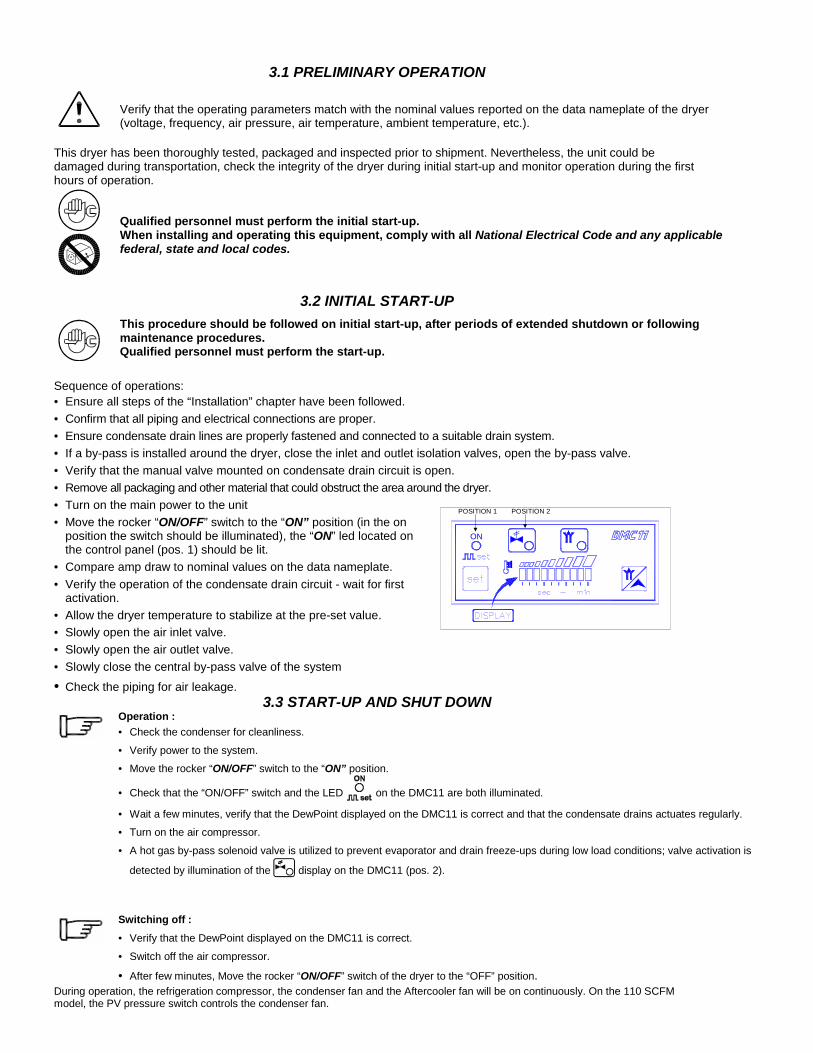
Sequence of operations: • Ensure all steps of the “Installation” chapter have been followed. • Confirm that all piping and electrical connections are proper. • Ensure condensate drain lines are properly fastened and connected to a suitable drain system. • If a by-pass is installed around the dryer, close the inlet and outlet isolation valves, open the by-pass valve. • Verify that the manual valve mounted on condensate drain circuit is open. • Remove all packaging and other material that could obstruct the area around the dryer. • Turn on the main power to the unit • Move the rocker “ON/OFF” switch to the “ON” position (in the on
position the switch should be illuminated), the “ON” led located on the control panel (pos. 1) should be lit.
• Compare amp draw to nominal values on the data nameplate. • Verify the operation of the condensate drain circuit - wait for first
activation. • Allow the dryer temperature to stabilize at the pre-set value. • Slowly open the air inlet valve. • Slowly open the air outlet valve. • Slowly close the central by-pass valve of the system • Check the piping for air leakage.
3.3 START-UP AND SHUT DOWN
Operation : • Check the condenser for cleanliness.
• Verify power to the system. • Move the rocker “ON/OFF” switch to the “ON” position.
• Check that the “ON/OFF” switch and the LED on the DMC11 are both illuminated.
• Wait a few minutes, verify that the DewPoint displayed on the DMC11 is correct and that the condensate drains actuates regularly. • Turn on the air compressor.
• A hot gas by-pass solenoid valve is utilized to prevent evaporator and drain freeze-ups during low load conditions; valve activation is
detected by illumination of the display on the DMC11 (pos. 2).
Switching off : • Verify that the DewPoint displayed on the DMC11 is correct.
• Switch off the air compressor.
• After few minutes, Move the rocker “ON/OFF” switch of the dryer to the “OFF” position. During operation, the refrigeration compressor, the condenser fan and the Aftercooler fan will be on continuously. On the 110 SCFM model, the PV pressure switch controls the condenser fan.
POSITION 1 POSITION 2
ON
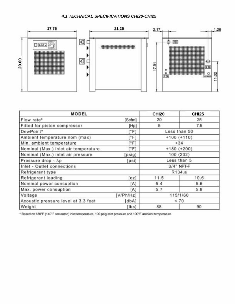
4.1 TECHNICAL SPECIFICATIONS CHI20-CHI25
C 00 CC 55
22 00.. 00
00
1
CHHII22
HHII227.75
21.25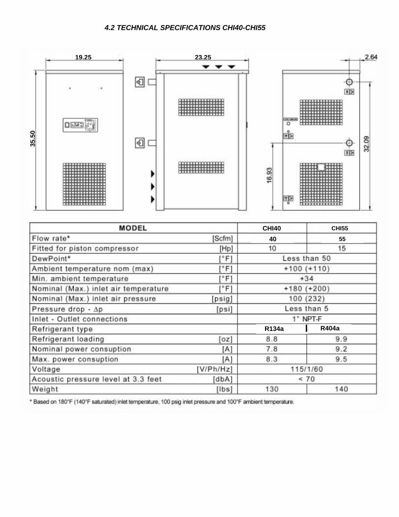
4.2 TECHNICAL SPECIFICATIONS CHI40-CHI55
CHI55 0
2
35.5
0
CHI4
3.25
19.2555
R
40
134a ❘❘❘❘ R
404a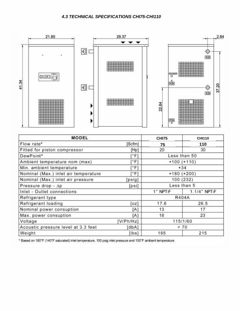
4.3 TECHNICAL SPECIFICATIONS CHI75-CHI110
CHI110 5
CHI7 1105 7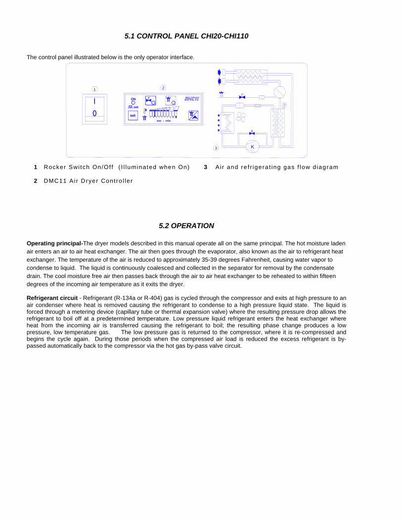
5.1 CONTROL PANEL CHI20-CHI110
The control panel illustrated below is the only operator interface.
0
1 ON
set
set
3 K
1 2
1 Rocker Swi tch On/Of f ( I l luminated when On) 3 Air and ref r igera t ing gas f low d iagram
2 DMC11 Ai r Dryer Contro l ler
5.2 OPERATION
Operating principal-The dryer models described in this manual operate all on the same principal. The hot moisture laden air enters an air to air heat exchanger. The air then goes through the evaporator, also known as the air to refrigerant heat exchanger. The temperature of the air is reduced to approximately 35-39 degrees Fahrenheit, causing water vapor to condense to liquid. The liquid is continuously coalesced and collected in the separator for removal by the condensate drain. The cool moisture free air then passes back through the air to air heat exchanger to be reheated to within fifteen degrees of the incoming air temperature as it exits the dryer. Refrigerant circuit - Refrigerant (R-134a or R-404) gas is cycled through the compressor and exits at high pressure to an air condenser where heat is removed causing the refrigerant to condense to a high pressure liquid state. The liquid is forced through a metering device (capillary tube or thermal expansion valve) where the resulting pressure drop allows the refrigerant to boil off at a predetermined temperature. Low pressure liquid refrigerant enters the heat exchanger where heat from the incoming air is transferred causing the refrigerant to boil; the resulting phase change produces a low pressure, low temperature gas. The low pressure gas is returned to the compressor, where it is re-compressed and begins the cycle again. During those periods when the compressed air load is reduced the excess refrigerant is by-passed automatically back to the compressor via the hot gas by-pass valve circuit.
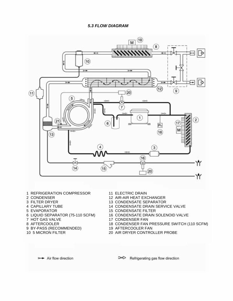
5.3 FLOW DIAGRAM
5.4 Flow Diagram for Model Series CNC20-CNC55
1 REFRIGERATION COMPRESSOR 11 ELECTRIC DRAIN 2 CONDENSER 12 AIR-AIR HEAT EXCHANGER 3 FILTER DRYER 13 CONDENSATE SEPARATOR 4 CAPILLARY TUBE 14 CONDENSATE DRAIN SERVICE VALVE 5 EVAPORATOR 15 CONDENSATE FILTER 6 LIQUID SEPARATOR (75-110 SCFM) 16 CONDENSATE DRAIN SOLENOID VALVE 7 HOT GAS VALVE 17 CONDENSER FAN 8 AFTERCOOLER 18 CONDENSER FAN PRESSURE SWITCH (110 SCFM)9 BY-PASS (RECOMMENDED) 19 AFTERCOOLER FAN 10 5 MICRON FILTER 20 AIR DRYER CONTROLLER PROBE

5.4 REFRIGERATION COMPRESSOR The refrigeration compressor is the pump of the system where the gas coming from the evaporator (low pressure side) is compressed up to the condensation pressure (high pressure side). The compressors utilized are manufactured by primary companies and are designed for applications where high compression ratios and wide temperature changes are present. The fully sealed construction is perfectly gas tight, so ensuring high-energy efficiency and long useful life. Dumping springs supports the pumping unit, in order to consistently reduce the acoustic emission and the vibration diffusion. The electric motor is cooled by the aspirated refrigerating gas, which goes through the coils before reaching the compression cylinders. The thermal protection protects the compressor from over heating and over currents. The protection is automatically restored as soon as the nominal temperature conditions are reached.
5.5 CONDENSER UNIT The condenser is the element in which the gas coming from the compressor is cooled down and condensed becoming a liquid. Mechanically, a copper tubing circuit (with the gas flowing inside) forms it immersed in an aluminum fin package. The cooling operation occurs via a high efficiency fan, which, in applying pressure on the air contained within the dryer, forces it into the fin package. It’s mandatory that the temperature of the ambient air will not exceed the nominal values. It is also important TO KEEP THE UNIT FREE FORM DUST AND OTHER IMPURITIES.
5.6 FILTER DRIER Traces of humidity and slag can accumulate inside the refrigeration circuit, or long periods of use can produce sludge, could limit the lubrication of the compressor and clog the expansion valve or capillary tube. The function of the filter drier, located before the capillary tubing, is to stop the impurities, avoiding their circulation within the system.
5.7 CAPILLARY TUBING It consists of a piece of reduced cross section copper tubing located between the condenser and the evaporator and acts as a metering device to reduce the pressure of the refrigerant. Reduction of pressure is a function of the temperature to be reached within the evaporator: the smaller the capillary tube outlet pressure, the lower the evaporation temperature. The length and interior diameter of the capillary tubing is accurately sized with the performance to be reached by the dryer; no maintenance or adjustment is necessary.
5.8 EVAPORATOR Also called an air-refrigerant exchanger. The liquid refrigerant formed in the condenser is evaporated in this part of the circuit. In the evaporation phase the refrigerant side of the evaporator tends to absorb heat from the compressed air present in the other side of the exchanger. The evaporator is immersed in the cabinet base of the dryer and insulated with non-CFC expanded insulating foam. The part is entirely constructed in copper and the cooler goes in the opposite direction to the air, thus contributing to limited pressure loss and to provide efficient thermal exchange.
5.9 LIQUID SEPARATOR (CHI75 & CHI110 only) It prevents the return of liquid refrigerant to the compressor separating droplets not evaporated from the gas flow.
5.10 HOT GAS BY-PASS SOLENOID VALVE This valve is located between the pressure side of the compressor and the terminal side of the evaporator. Its purpose is to avoid conditions of low thermal charge in the dryer (low air flow or relatively cold air) The temperature inside the evaporators will drop below 32ºF. Temperature below 32ºF would eventually allow the formation of ice inside the evaporator, with the consequent blockage of air flow and, in the worst of the cases, the rupture of the evaporator itself. The DMC11 Controller activates the coil of the solenoid valve.
5.11 5-MICRON FILTER Positioned at the outlet of the Aftercooler, the 5-micron filter ensures a good degree of purification of the treated air. The filter unit is embodied in the container so as to ensure rapid and easy replacement.
5.12 AFTERCOOLER
The air Aftercooler is the component where the hot air entering the dryer undergoes preliminary cooling down. It consists of a circuit of copper tubing, supporting the circulation of compressed air, immersed in an aluminum body provided with cooling fins. A high efficiency axial fan moving ambient air onto these blades provides the necessary cooling down of the system. It is mandatory that the ambient temperature will not exceed the nominal value for the dryer. It is equally important to KEEP THIS SYSTEM FREE FROM DUST AND FOREIGN MATERIALS eventually introduced by the fan.
5.13 AIR/AIR EXCHANGER The purpose of this exchanger is the transmission of the heat of the incoming air to the exiting cold air. The benefits of this solution are basically twofold: the incoming air is partially cooled down. Therefore the chilling system can be sized for a lower thermal drop, thus allowing a 40-50% energy saving; moreover, cool air will never reach the compressed air circuit and condensate will not form on the external surface of the piping.
5.14 CONDENSATE SEPARATOR The cold air exiting the evaporator goes through the "demister" type condensate separator featuring a stainless steel net. As the condensate transported by the air gets in contact with the metallic net of the "demister" it is separated and expelled by means of the draining device. The resulting cold and dry air is then conveyed into the air/air exchanger. The "demister" type separator offers the benefit of being highly efficient, even with variable flow rates and does not require special maintenance.
5.15 COOLING FLUID PRESSURE SWITCH PV (CHI110 only) To safeguard a safety operation and the integrity of the dryer, a pressure controller has been installed on the refrigerating gas circuit. PV: Condenser fan control switch located on the inlet side on the compressor keeps the condensation temperature/pressure constant within preset limits. Setting pressure: R 404A Stop 232 psi/104ºF - Restart 290 psi/115ºF
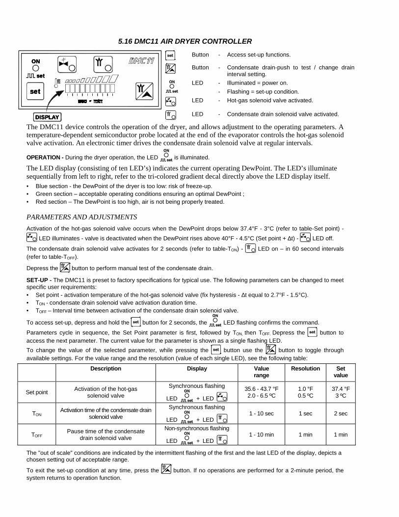
5.16 DMC11 AIR DRYER CONTROLLER
Button - Access set-up functions.
Button - Condensate drain-push to test / change drain
interval setting.
LED -
- Illuminated = power on. Flashing = set-up condition.
LED - Hot-gas solenoid valve activated.
OOOONNNN
sssseeeetttt
sssseeeetttt
DDDDIIIISSSSPPPPLLLLAAAAYYYY LED - Condensate drain solenoid valve activated.
The DMC11 device controls the operation of the dryer, and allows adjustment to the operating parameters. A temperature-dependent semiconductor probe located at the end of the evaporator controls the hot-gas solenoid valve activation. An electronic timer drives the condensate drain solenoid valve at regular intervals.
OPERATION - During the dryer operation, the LED is illuminated.
The LED display (consisting of ten LED’s) indicates the current operating DewPoint. The LED’s illuminate sequentially from left to right, refer to the tri-colored gradient decal directly above the LED display itself. • Blue section - the DewPoint of the dryer is too low: risk of freeze-up. • Green section – acceptable operating conditions ensuring an optimal DewPoint ; • Red section – The DewPoint is too high, air is not being properly treated.
PARAMETERS AND ADJUSTMENTS Activation of the hot-gas solenoid valve occurs when the DewPoint drops below 37.4°F - 3°C (refer to table-Set point) -
LED illuminates - valve is deactivated when the DewPoint rises above 40°F - 4.5°C (Set point + ∆t) - LED off.
The condensate drain solenoid valve activates for 2 seconds (refer to table-TON) - LED on – in 60 second intervals (refer to table-TOFF).
Depress the button to perform manual test of the condensate drain.
SET-UP - The DMC11 is preset to factory specifications for typical use. The following parameters can be changed to meet specific user requirements: • Set point - activation temperature of the hot-gas solenoid valve (fix hysteresis - ∆t equal to 2.7°F - 1.5°C). • TON - condensate drain solenoid valve activation duration time. • TOFF – Interval time between activation of the condensate drain solenoid valve.
To access set-up, depress and hold the button for 2 seconds, the LED flashing confirms the command.
Parameters cycle in sequence, the Set Point parameter is first, followed by TON, then TOFF. Depress the button to access the next parameter. The current value for the parameter is shown as a single flashing LED. To change the value of the selected parameter, while pressing the button use the button to toggle through available settings. For the value range and the resolution (value of each single LED), see the following table:
Description Display Value range
Resolution Set value
Set point Activation of the hot-gas solenoid valve
Synchronous flashing
LED + LED 35.6 - 43.7 °F 2.0 - 6.5 ºC
1.0 °F 0.5 ºC
37.4 °F 3 ºC
TON Activation time of the condensate drain solenoid valve
Synchronous flashing
LED + LED 1 - 10 sec 1 sec 2 sec
TOFF Pause time of the condensate drain solenoid valve
Non-synchronous flashing
LED + LED 1 - 10 min 1 min 1 min
The "out of scale" conditions are indicated by the intermittent flashing of the first and the last LED of the display, depicts a chosen setting out of acceptable range.
To exit the set-up condition at any time, press the button. If no operations are performed for a 2-minute period, the system returns to operation function.
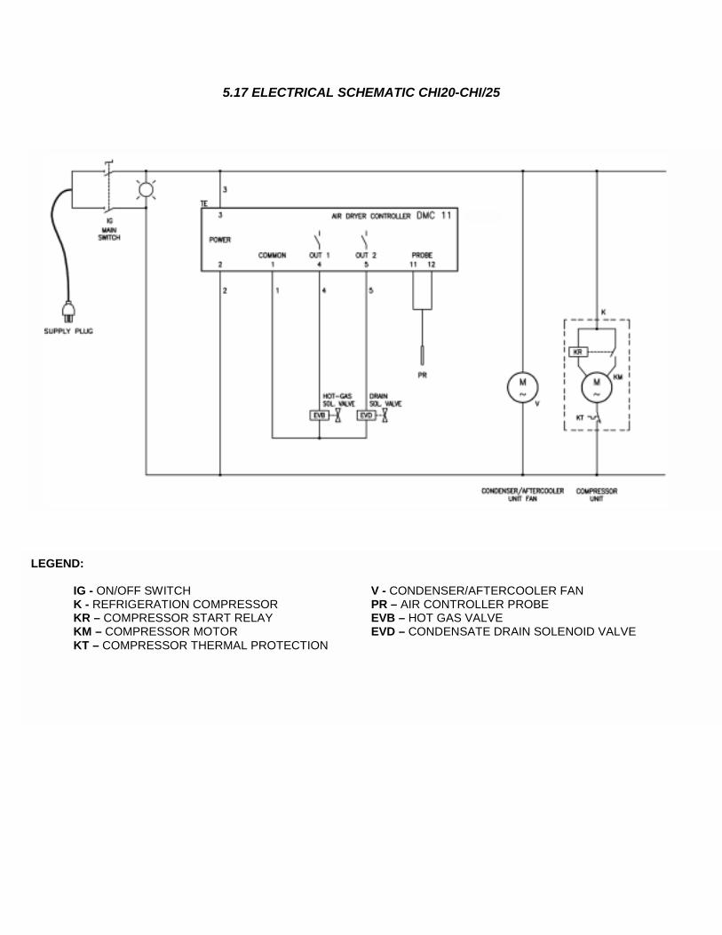
5.17 ELECTRICAL SCHEMATIC CHI20-CHI/25
LEGEND: IG - ON/OFF SWITCH V - CONDENSER/ K - REFRIGERATION COMPRESSOR PR – AIR CONTR KR – COMPRESSOR START RELAY EVB – HOT GAS V KM – COMPRESSOR MOTOR EVD – CONDENS KT – COMPRESSOR THERMAL PROTECTION
AFTERCOOLER FAN OLLER PROBE
ALVE ATE DRAIN SOLENOID VALVE

5.18 ELECTRICAL SCHEMATIC CHI40-CHI75
LEGEND: IG - ON/OFF SWITCH VC - CONDEN K - REFRIGERATION COMPRESSOR VA - AFTERCO KR – COMPRESSOR START RELAY PR – AIR CON KM – COMPRESSOR MOTOR EVB – HOT GA KT – COMPRESSOR THERMAL PROTECTION EVD – CONDE
SER FAN OLER FAN TROLLER PROBE S VALVE NSATE DRAIN SOLENOID VALVE
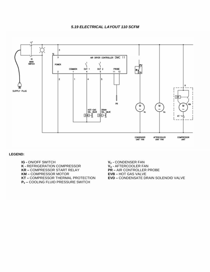
5.19 ELECTRICAL LAYOUT 110 SCFM
LEGEND: IG - ON/OFF SWITCH VC - CONDENS K - REFRIGERATION COMPRESSOR VA - AFTERCO KR – COMPRESSOR START RELAY PR – AIR CON KM – COMPRESSOR MOTOR EVB – HOT GA KT – COMPRESSOR THERMAL PROTECTION EVD – CONDE PV – COOLING FLUID PRESSURE SWITCH
ER FAN OLER FAN TROLLER PROBE S VALVE NSATE DRAIN SOLENOID VALVE
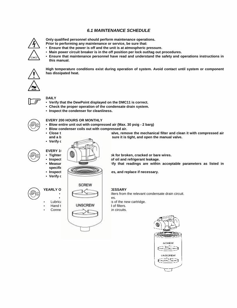
6.1 MAINTENANCE SCHEDULE
Only qualified personnel should perform maintenance operations. Prior to performing any maintenance or service, be sure that: • Ensure that the power is off and the unit is at atmospheric pressure. • Main power circuit breaker is in the off position per lock out/tag out procedures. • Ensure that maintenance personnel have read and understand the safety and operations instructions in
this manual.
High temperature conditions exist during operation of system. Avoid contact until system or component has dissipated heat.
DAILY • Verify that the DewPoint displayed on the DMC11 is correct. • Check the proper operation of the condensate drain system. • Inspect the condenser for cleanliness.
EVERY 200 HOURS OR MONTHLY • Blow entire unit out with compressed air (Max. 30 psig - 2 barg) • Blow condenser coils out with compressed air. • Close the manual condensate drain valve, remove the mechanical filter and clean it with compressed air
and a brush. Reinstall the filter, make sure it is tight, and open the manual valve. • Verify operation of the machine.
EVERY 1000 HOURS OR YEARLY • Tighten all electrical connections. Look for broken, cracked or bare wires. • Inspect refrigeration circuit for signs of oil and refrigerant leakage. • Measure and record amperage. Verify that readings are within acceptable parameters as listed in
specification table. • Inspect condensate drain flexible hoses, and replace if necessary. • Verify operation of the machine.
YEARLY OR MORE FREQUENTLY IF NECESSARY • Disconnect the 5-micron filters from the relevant condensate drain circuit. • Unscrew the clogged cartridges.
• Lubricate with silicon grease the gaskets of the new cartridge. • Hand tighten the cartridges on the head of filters. • Connect the respective condensate drain circuits.

6.2 SPARE PARTS
Model CHI20 CHI25 CHI40 CHI55 CHI75 CHI110Part Description Qty Part Numbers Part Numbers Part Numbers Part Numbers Part Numbers Part Numbers
Condenser 1 5821005005 5821005005 5810010005 5810010005 5810020005 5810030005Fan Motor 1 5210135015 5210135015 52100135015 52100135015 5210135020 5210135020Fan Blade 1 5215000022 5215000022 5215000022 5215000022 5215000025 5215000025Aftercooler Condenser 1 * * 5820010005 5820010005 5820020005 5820030005Aftercooler Fan Motor 1 * * 5210135015 5210135015 5210135020 5210135020Aftercooler Fan Blade 1 * * 5215000022 5215000022 5215000025 5215000025Compressor 1 5015135005 5015135007 5015135010 5025135003 5025135005 5025135015Filter Drier 1 6650SSS005 6650SSS005 6650SSS005 6650SSS005 6650SSS005 6650SSS005By-Pass Solenoid Valve 1 64120SS005 64120SS005 64120SS005 64120SS005 64120SS005 64120SS005(+) By-pass Solenoid Coil 1 64N22MM055 64N22MM055 64N22MM055 64N22MM055 64N22MM055 64N22MM055DMC11 Controller 1 5620130100 5620130100 5620130100 5620130100 5620130100 5620130100DMC11 Probe 1 5625NNN020 5625NNN020 5625NNN035 5625NNN035 5625NNN035 5625NNN035Green Indicator Switch 1 5450SZN010 5450SZN010 5450SZN010 5450SZN010 5450SZN010 5450SZN010Shut Off Ball Valve 3/8" 1 64130MF150 64130MF150 64130MF150 64130MF150 64130MF150 64130MF150Y- Strainer 3/8" 1 64355FF011 64355FF011 64355FF011 64355FF011 64355FF011 64355FF011Auto Drain Trap ATD02 1 2230ATD002 2230ATD002 2230ATD002 2230ATD002 2230ATD002 2230ATD002Condensate Solenoid Valve 1/4" 1 64320FF005 64320FF005 64320FF005 64320FF005 64320FF005 64320FF005(+) Condensate Solenoid Coil 1 64N22MM035 64N22MM035 64N22MM035 64N22MM035 64N22MM035 64N22MM035(+) Replacement Spin on Filter 5 Micron 1 1500LFP006 1500LFP012 1500LFP012 1500LFP018 1500LFP023 1500LPF045Front Panel 1 680TH005ANDF 680TH005ANDF 680TH010ANDF 680TH010ANDF 680TH020ANDF 680TH020ANDFBack Panel 1 680TH005PSTF 680TH005PSTF 680TH010PSTF 680TH010PSTF 680TH020PSTF 680TH020PSTFSide Panels (Right & Left) 1 680TH005LTRF 680TH005LTRF 680TH010LTRF 680TH010LTRF 680TH020LTRF 680TH020LTRFTop 1 680DF003CPRF 680DF003CPRF 680TH010CPRF 680TH010CPRF 680TH020CPRF 680TH020CPRF
* Parts not required on model.(+) Recommended Spare Parts
Spare Parts List

7.1 TROUBLESHOOTING
The troubleshooting and the eventual checks have to be worked out by qualified personnel. Pay particular attention in entering the refrigerating circuit. The refrigerant if under pressure, while expanding could cause burns and serious damage to the eyes, should it gets in contact with them.SYMPTOM POSSIBLE CAUSE - SUGGESTED ACTION The machine doesn't start. Check for power failure. Verify the electric wiring. The compressor doesn’t work. Activation of the internal protection - wait for 30 minutes, then retry. Verify the electric wiring. Replace the internal protection. If present, replace the start-up relay.
If present, replace the start-up capacitor. If present, replace the run capacitor.
If the compressor still doesn’t work, replace. The fan of the condenser doesn’t work. Verify the electric wiring.
The PV pressure switch is faulty (25 SCFM) -contact refrigeration engineer to replace it. If the fan still doesn’t work, replace.
The fan of the final refrigerant Verify the electric wiring. Doesn’t work. If the fan still doesn’t work, replace. The dryer doesn’t drain the Verify the electric wiring. condensate. The condensate drain mechanical filter is clogged- remove and clean. The drain solenoid valve is jammed - remove and clean. The coil of the condensate drain solenoid valve burned out - replace. Air Dry Controller doesn’t work - replace. The DewPoint is too low - the condensate is frost - see the specific section. The dryer continuously drains The drain solenoid valve is jammed - remove and clean. condensate. Air Dryer Controller doesn’t work - replace. Water within the line. The dryer is off - switch it on.
Untreated air flows through the by-pass unit (if installed) - close the by-pass. The dryer doesn’t drain condensate - see the specific section. DewPoint too high - see the specific section. DewPoint too high. The dryer is off - switch it on. The refrigerating compressor doesn’t work - see the specific section. The fan of the condenser doesn’t work - see the specific section. The fan of the Aftercooler doesn’t work - see the specific section. The inlet air is too hot - restore the nominal conditions.
The inlet airflow rate is higher than the rate of the dryer - reduce the flow rate - restore the normal conditions. The ambient temperature is too high or the room ventilation is insufficient - provide proper ventilation.
The condenser is dirty - clean. The Aftercooler is dirty - clean.
Th dryer doesn’t drain the condensate - see the specific section. LE of the Air Dry Controller is always on - see specific paragraph.
ThCoThen
e D
e set point of the Air Dry Controller is very high - see SET-UP of the Air Dry ntroller. ere is a leak in the refrigerating circuit - contact a refrigerating systems gineer.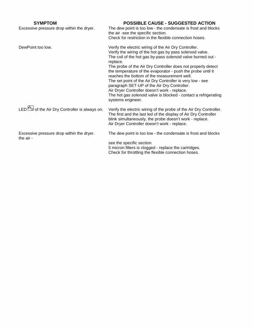
SYMPTOM POSSIBLE CAUSE - SUGGESTED ACTION Excessive pressure drop within the dryer. The dew point is too low - the condensate is frost and blocks
the air -see the specific section. Check for restriction in the flexible connection hoses. DewPoint too low. Verify the electric wiring of the Air Dry Controller. Verify the wiring of the hot gas by pass solenoid valve.
The coil of the hot gas by-pass solenoid valve burned out - replace. The probe of the Air Dry Controller does not properly detect the temperature of the evaporator - push the probe until it reaches the bottom of the measurement well. The set point of the Air Dry Controller is very low - see paragraph SET-UP of the Air Dry Controller. Air Dryer Controller doesn’t work - replace. The hot gas solenoid valve is blocked - contact a refrigerating systems engineer.
LED of the Air Dry Controller is always on. Verify the electric wiring of the probe of the Air Dry Controller.
The first and the last led of the display of Air Dry Controller blink simultaneously, the probe doesn’t work - replace.
Air Dryer Controller doesn’t work - replace. Excessive pressure drop within the dryer. The dew point is too low - the condensate is frost and blocks the air -
see the specific section. 5 micron filters is clogged - replace the cartridges. Check for throttling the flexible connection hoses.
For complete line of additional product information, please contact your local COAIRE distributor.
DISTRIBUTED BY
COAIRE Technologies reverse the right to make changes, at any time without notice as a result of our commitment to continuous improvement.
Coaire Technologies, Corporation 12226 Coast Drive, Whittier, CA 90601 ◊ TEL.(562)463-3935 ◊ (562)463-4928
website: www.coaire.com ■ e-mail: [email protected]/[email protected]