Embed Size (px)
Citation preview

INSTALLATION, OPERATION
& MAINTENANCE MANUAL
BERG TEMPERATURE CONTROL UNIT
BERG CHILLING SYSTEMS INC. Operation & Maintenance Manual
BERG SERIES TEMPERATURE CONTROL UNIT Page 2
TABLE OF CONTENTS
Description Page # Introduction 3 Customer Support 3 Model Number Nomenclature 4 Control Panel 5 Display Panel Menu Navigation 6 Controller Home Page 7
Controller Display 8 Alarm Events and Controller Parameters 9 Set Up Procedure 9
Water Hook Up 10 Electrical Hook Up 11 Basic Start Up Procedures 12 Shut Down Procedures 13 Disassembly and Reassembly Procedures 14 Scott Pump 15 Troubleshooting 17
Plumbing Diagram 18 Electrical Diagrams 19

BERG CHILLING SYSTEMS INC. Operation & Maintenance Manual
BERG SERIES TEMPERATURE CONTROL UNIT Page 3
INTRODUCTION On behalf of everyone at Berg Chilling Systems, thank you for purchasing this equipment. With over 35 years experience in developing and implementing customized Process Cooling solutions for customers around the world, we firmly believe that our equipment is second to none and that the solution provided for you in this equipment has been engineered and manufactured using only the highest quality, state of the art components, to give trouble free service with a minimum of maintenance. It is in everyone’s best interest if you read this manual thoroughly and where applicable, familiarize yourself with the checklists and tips contained here, and adhere to the safety and maintenance schedules outlined. Proper care and attention to maintenance and operating procedures will ensure an extended service life and minimum downtime of your equipment. Berg will not be liable for errors contained in this manual or any damages in connection with the use of this manual. CUSTOMER SUPPORT If you have any questions in regards to this manual or if you have any problems with your unit, consult the factory at 416-755-2221. For 24 hour service inquiries, Please call (416) 755 - 2226 Head Office: Berg Chilling Systems Inc. 51 Nantucket Blvd., Toronto, Ontario, Canada M1P 2N5 Tel : (416) 755-2221. Fax : (416) 755-3874. Email:[email protected] Internet : www.berg-group.com
BERG CHILLING SYSTEMS INC. Operation & Maintenance Manual
BERG SERIES TEMPERATURE CONTROL UNIT Page 4
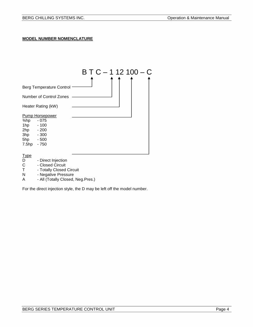
MODEL NUMBER NOMENCLATURE B T C – 1 12 100 – C Berg Temperature Control Number of Control Zones Heater Rating (kW) Pump Horsepower ¾hp - 075 1hp - 100 2hp - 200 3hp - 300 5hp - 500 7.5hp - 750 Type D - Direct Injection C - Closed Circuit T - Totally Closed Circuit N - Negative Pressure A - All (Totally Closed, Neg.Pres.) For the direct injection style, the D may be left off the model number.
BERG CHILLING SYSTEMS INC. Operation & Maintenance Manual
BERG SERIES TEMPERATURE CONTROL UNIT Page 5
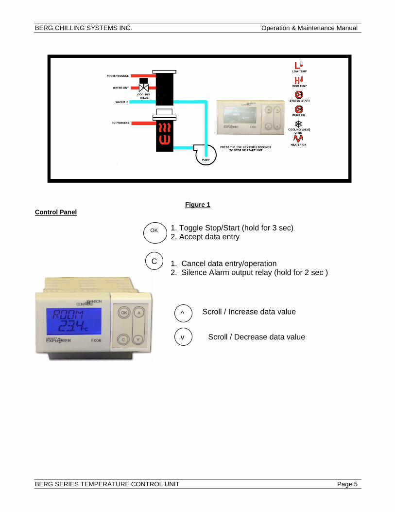
Figure 1 Control Panel 1. Toggle Stop/Start (hold for 3 sec) 2. Accept data entry 1. Cancel data entry/operation 2. Silence Alarm output relay (hold for 2 sec )
C
^
v
Scroll / Increase data value
Scroll / Decrease data value
OK

BERG CHILLING SYSTEMS INC. Operation & Maintenance Manual
BERG SERIES TEMPERATURE CONTROL UNIT Page 6
Menu Navigation Using “C” and scroll keys Menu Pages To/From Sensor Page Active alarm events are displayed until any key is pressed.
Home Page
Sensors C
C
Events Page
Password Page
System Page
C
C
C
Events are archived until repaired

BERG CHILLING SYSTEMS INC. Operation & Maintenance Manual
BERG SERIES TEMPERATURE CONTROL UNIT Page 7
Controller Home Page TEMP TEMP SETPOINT OC/OF WATER PRESSURE PSI SUPPLY OC/OF RETURN OC/OF PUMP ON/OFF HI TEMP ALAR LO TEMP ALAR UNITS OF MEASURE PRI ( OC) SECO ( OF) ALARM ON/OFF Sensors Page PROCESS OK/BAD RETURN OK.BAD PRESSURE OK/BAD System Page LCD CONTRAST BACKLIGHT DEFAULT COLOR Blue (Red) ALARM COLOR Red/Blue Address 255 HOUR MINUTES DAY OF WEEK DAY MONTH YEAR

BERG CHILLING SYSTEMS INC. Operation & Maintenance Manual
BERG SERIES TEMPERATURE CONTROL UNIT Page 8
Controller Display
PRESS “OK” FOR 2 SECONDS TO STOP OR START THE UNIT
SYSTEM START
LOW TEMP ALARM
HIGH TEMP ALARM
PUMP STATUS
HEATER STATUS COOLING/VENT STATUS
DISPLAY ICON LEGEND

BERG CHILLING SYSTEMS INC. Operation & Maintenance Manual
BERG SERIES TEMPERATURE CONTROL UNIT Page 9
Events System Error High Temp Low Temp Pump Fail Low Press Process Sensor Fail Supply Sensor Fail Pressure Sensor Fail Parameters (Password protected page) Return Sensor Offset Process Sensor Offset Hi Temp Alarm Shift Lo Temp Alarm Shift Heater Differential Heater Setpoint Offset Vent Time Period Percent Open Prop Band Integral Heater Control sensor selection SV Control sensor selection Pressure sensor offset Pressure sensor Upper Range Value Pressure sensor Lower Range Value Lo Pressure Trip Setpoint DAT Output PT Filter Weight SET UP PROCECURE Location The Berg Temperature Controller Unit should be located as close to the process machine as possible. A minimum footprint of 16-1/4” wide and 28” deep is required on a level surface. Rear clearance is only required to make the necessary water line hookups.
Air Temperature and Humidity The Temperature Controller should be in a clean, well ventilated area with a maximum room temperature of 120°F with 95% relative humidity, non-condensing and a minimum air temperature of 32°F.

BERG CHILLING SYSTEMS INC. Operation & Maintenance Manual
BERG SERIES TEMPERATURE CONTROL UNIT Page 10
WATER HOOK-UP
(SEE FIGURE 3)
Pressure Requirements The Berg Temperature Control Units require a minimum of 25 PSI on the cooling water input and accommodate a maximum of 85 PSI. Note: 30 PSI to 50 PSI provides the optimum operation of the unit.
To and From Process The to process and from process hookups should be connected in the back of the unit with 1¼” NPT piping. Both hookups are clearly marked on the back of the unit.
Cooling Water In and Out The cooling water in and cooling water out hookups should be connected in the back of the unit with ¾” NPT piping. Both hookups are clearly marked on the back of the unit.
Cooling Water
Cooling Water

BERG CHILLING SYSTEMS INC. Operation & Maintenance Manual
BERG SERIES TEMPERATURE CONTROL UNIT Page 11
Figure 5
Groun
L3 L2 L1
ELECTRICAL HOOK-UP
Always maintain a safe ground and always disconnect incoming power before you open the unit or perform any nonstandard operating procedures, such as routine maintenance. Improper power supply could result in damage to the unit as well as serious injury to the operator!
1. Before power is initiated to the unit, make sure the specifications stated on the nameplate are met. See Figure 4 for the location of the nameplate. The electrical hookup should be identical with a maximum of ±10% variance in voltage. The electrical hookup should also run through a fused disconnect, sized in accordance with the nameplate amperage and conforming to Article 250 of the National Electrical Code.
2. Connect the power feed to the right side of the unit. Bring the four wires through the hole on the right side of the electrical enclosure. See Figure 4.
3. Connect the three hot wires to L1, L2 and L3 on the terminal block in the upper right hand corner of the electrical enclosure. See Figure 5.
4. Connect the ground wire to the copper grounding mount to the left of the terminal block. See Figure 5.
BERG CHILLING SYSTEMS INC. Operation & Maintenance Manual
BERG SERIES TEMPERATURE CONTROL UNIT Page 12
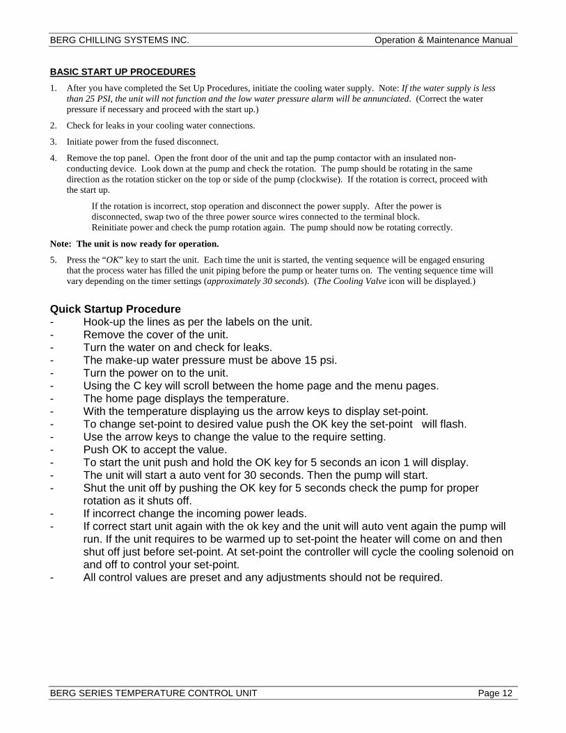
BASIC START UP PROCEDURES
1. After you have completed the Set Up Procedures, initiate the cooling water supply. Note: If the water supply is less than 25 PSI, the unit will not function and the low water pressure alarm will be annunciated. (Correct the water pressure if necessary and proceed with the start up.)
2. Check for leaks in your cooling water connections.
3. Initiate power from the fused disconnect.
4. Remove the top panel. Open the front door of the unit and tap the pump contactor with an insulated non-conducting device. Look down at the pump and check the rotation. The pump should be rotating in the same direction as the rotation sticker on the top or side of the pump (clockwise). If the rotation is correct, proceed with the start up.
If the rotation is incorrect, stop operation and disconnect the power supply. After the power is disconnected, swap two of the three power source wires connected to the terminal block. Reinitiate power and check the pump rotation again. The pump should now be rotating correctly.
Note: The unit is now ready for operation.
5. Press the “OK” key to start the unit. Each time the unit is started, the venting sequence will be engaged ensuring that the process water has filled the unit piping before the pump or heater turns on. The venting sequence time will vary depending on the timer settings (approximately 30 seconds). (The Cooling Valve icon will be displayed.)
Quick Startup Procedure - Hook-up the lines as per the labels on the unit. - Remove the cover of the unit. - Turn the water on and check for leaks. - The make-up water pressure must be above 15 psi. - Turn the power on to the unit. - Using the C key will scroll between the home page and the menu pages. - The home page displays the temperature. - With the temperature displaying us the arrow keys to display set-point. - To change set-point to desired value push the OK key the set-point will flash. - Use the arrow keys to change the value to the require setting. - Push OK to accept the value. - To start the unit push and hold the OK key for 5 seconds an icon 1 will display. - The unit will start a auto vent for 30 seconds. Then the pump will start. - Shut the unit off by pushing the OK key for 5 seconds check the pump for proper
rotation as it shuts off. - If incorrect change the incoming power leads. - If correct start unit again with the ok key and the unit will auto vent again the pump will
run. If the unit requires to be warmed up to set-point the heater will come on and then shut off just before set-point. At set-point the controller will cycle the cooling solenoid on and off to control your set-point.
- All control values are preset and any adjustments should not be required.

BERG CHILLING SYSTEMS INC. Operation & Maintenance Manual
BERG SERIES TEMPERATURE CONTROL UNIT Page 13
1/4” Plug 1/4” Plug
Figure 8 Bottom of Mixing Tube 1/4” Plug (2 Places)
Pump Volute Compression Fitting
Side View of Pump Figure 9
SHUT DOWN PROCEDURES Shut Down to Change Water Line Hook-Up Allow the process temperature to cool to at least 120°F. Press the stop button to stop operation of the unit. Close the cooling process water input. Press the start button or open the relief valve on the back of the unit to relieve pressure. Drain the water from the unit using both 1/4” plugs on the lower back of the unit. See Figure 8. Once the unit is cooled to at least 120° and the water is drained, the water hook-ups can be removed. Shut Down for Mold Purge (Option) To prepare for mold purge, just press the stop button to stop operation of the unit and close the cooling process water input. Connect the compressed air (80 to 100 PSI recommended) and hit the mold purge button. The mold purge will continue until timer 2 is timed out. Shut Down for Relocation When relocating the unit within the same general area, press the stop button. The water feeds may or may not need to be disconnected depending on the new location. Shut Down for Storage or Shipment Shut down the unit as you would for changing the water line hook-up. Then loosen the compression fitting at the pump volute. See Figure 9. Take extra care to make sure all trapped water is drained from the bottom of the mixing/heater tubes and the pump volute. This trapped water will freeze at 32° or below. The expansion of this freezing water can/will damage the equipment. Note: The Temperature Controller Unit can withstand temperatures as low as -40°F when shipping and storing the completely drained unit.

BERG CHILLING SYSTEMS INC. Operation & Maintenance Manual
BERG SERIES TEMPERATURE CONTROL UNIT Page 14
Red
Solenoid with 1/2” NPT
Spring
Core Spring
Body
Nameplate/Retain
Solenoid Base Sub-
0.9375-26 UNS-2A
Core Assembly
Valve Body 1/4” NPT Brass
See Step 4
Grounding Wire Green or Green with Yellow
DISASSEMBLY AND REASSEMBLY PROCEDURES Cooling Solenoid
1. Disconnect the water connections and drain the unit completely.
2. Remove the red cap.
3. Push the solenoid down.
4. With a flathead screwdriver, remove the nameplate/retainer by prying under and pushing the nameplate/retainer.
5. For reassembly, make sure to put the wide end of the core spring into the core first. The closed end protrudes from the top of the core.
BERG CHILLING SYSTEMS INC. Operation & Maintenance Manual
BERG SERIES TEMPERATURE CONTROL UNIT Page 15
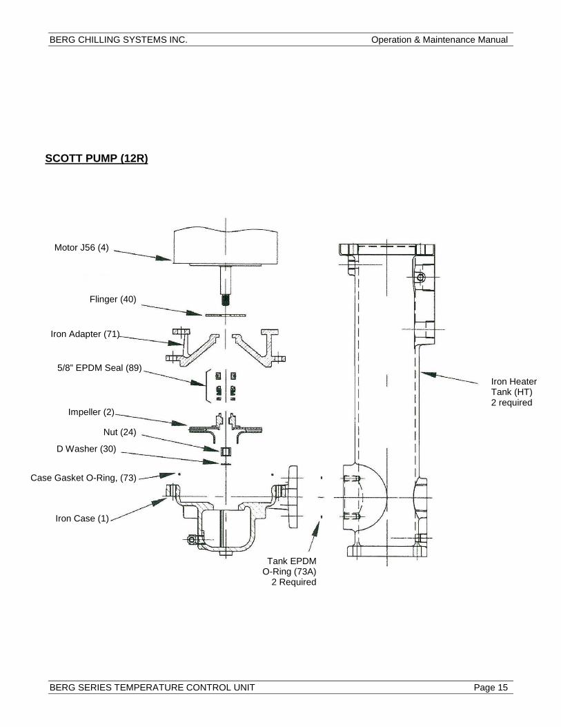
Motor J56 (4)
Flinger (40)
5/8” EPDM Seal (89)
Impeller (2)
Nut (24)
D Washer (30)
Case Gasket O-Ring, (73)
Iron Case (1)
Iron Adapter (71)
Iron Heater Tank (HT) 2 required
Tank EPDM O-Ring (73A)
2 Required
SCOTT PUMP (12R)

BERG CHILLING SYSTEMS INC. Operation & Maintenance Manual
BERG SERIES TEMPERATURE CONTROL UNIT Page 16
Motor JM 140/180
Flinger
Iron Adapter (71)
Seal Retainer (89A)
Case Gasket (73)
Impeller (2)
Key (32)
Impeller Retainer (26)
Bronze Shaft Sleeve (14)
Shaft BUNA O-Ring
1-1/2” EPDM Seal (89)
Bronze Wear Ring (25)
Iron Case
EPDM O-Ring (73A) 2 Required
Iron Heater Tank (HT) 2 Required
SCOTT PUMP (50R)

BERG CHILLING SYSTEMS INC. Operation & Maintenance Manual
BERG SERIES TEMPERATURE CONTROL UNIT Page 17
Troubleshooting When an error occurs, the display1 will alternate back and forth from the error code and current display readout. This section will describe the error codes and any actions you need to take to correct the problem.
Problem Possible Cause Solution Nothing happens, Display does not light up
Power feed is not connected correctly
Re-wire power feed
Power disconnect is off Turn on power disconnect Power fuses or breakers are open
Check fuse/breaker status
Control transformer fuses are blown
Check fuse continuity
Pump does not engage after vent sequence
Improperly set time delay ITD
Reset the ITD to 30 seconds
Defective time delay ITD Replace the ITD Pump overload tripped Reset overload if tripped Pump starter defective Replace the pump starter Pump motor defective Replace the pump motor
The power is on but the unit does not start or vent
Insufficient cooling water pressure
Water pressure must be 25 to 80 PSI
Defective water pressure switch
Replace the water pressure switch
Unit will not heat to set point
Cooling solenoid is leaking Clean seat or replace Heater or heater contactor failure
Check the amperage (each leg should be equal). Replace as required.
Optional high temp safety tripped
Preset 260°F cutout. Replace if required.