Embed Size (px)
Citation preview
1
Flow Control Division
Kammer Control Valves
Installation, Operation, Maintenance Instructions
Pneumatic andElectropneumatic ActuatorsSeries 4, Types 37, 38, 39, 3D and 47, 48, 49, 4D
1 USING KÄMMER VALVES AND ACTUATORSCORRECTLY
1.1 GeneralThe following instructions are designed to assist inunpacking, installing and performing maintenance asrequired on Kämmer products. Product users andmaintenance personnel should thoroughly review thisbulletin prior to installing, operating or performingany maintenance.DANGER: In most cases Kämmer valves and actuatorsare designed for specific applications (e.g. with regardto medium, pressure, temperature). For this reasonthey should not be used in other applications withoutfirst contacting the manufacturer.
1.2 Terms concerning safetyThe safety terms DANGER, WARNING, CAUTION andNOTE are used in these instructions to highlightparticular dangers and/or to provide additionalinformation on aspects that may not be readilyapparent.DANGER: indicates that death, severe personal injuryand/or substantial property damage will occur ifproper precautions are not taken.WARNING: indicates that death, severe personal injuryand/or substantial property damage can occur ifproper precautions are not taken.CAUTION: indicates that minor personal injury and/
Index1 Using Kämmer valves and actuators correctly.2 Unpacking3 Installation4 Quick check / Maintenance5 Methode of operation6 Remove and install actuator7 Disassemble and assemble actuator8 Calibration / Technical data
or property damage can occur if proper precautionsare not taken.NOTE: indicates and provides additional technicalinformation, which may not be very obvious even toqualified personnel.Compliance with other, not particularly emphasisednotes, with regard to transport, assembly, operationand maintenance and with regard to technicaldocumentation (e.g. in the operating instruction,product documentation or on the product itself) isessential, in order to avoid faults, which in themselvesmight directly or indirectly cause severe personalinjury or property damage.
1.3 Protective clothingKämmer products are often used in problematicapplications (e.g. extremely high pressures, dang-erous, toxic or corrosive mediums). In particularvalves with bellows seals point to such applications.When performing service, inspection or repairoperations always ensure, that the valve and actuatorare depressurised and that the valve has been cleanedand is free from harmful substances. In such casespay particular attention to personal protection(protective clothing, gloves, glasses etc.).
1.4 Qualified personnelQualified personnel are people who, on account oftheir training, experience and instruction and theirknowledge of relevant standards, specifications,accident prevention regulations and operatingconditions, have been authorised by those responsiblefor the safety of the plant to perform the necessarywork and who can recognise and avoid possibledangers.
1.5 InstallationDANGER: Before installation check the order-no,serial-no. and/or the tag-no. to ensure that the valve/actuator is correct for the intended application.Do not insulate extensions that are provided for hotor cold services.Pipelines must be correctly aligned to ensure that thevalve is not fitted under tension.
STOP!
KMEIM0006-00 - 08.03
2
Flow Control Division
Kammer Control Valves
2 UNPACKING2.1 Each delivery includes a packing slip. When unpack-
ing, check all delivered valves and accessories usingthis packing slip.
2.2 Larger valves can be lifted using slings on the yokerods or, if present, on the lugs provided for thispurpose. If slings are used, attach them so that theouter tubing or attaching parts are not damaged.
WARNING: If slings are used, be aware that the cen-tre of gravity of the valve may be above the liftingpoint. In this case, secure or support the valve againstrotating, to prevent damage or personnel injury.
2.3 Report transport damage to the carrier immediately.2.4 In case of discrepancies, contact your nearest
FLOWSERVE sales office.3 INSTALLATION3.1 Clean tubing prior to installing.3.2 If possible, install the valve in an upright position
(actuator on top), to ease maintenance. An uprightinstallation position is important with low-tempera-ture applications, in order to keep the distance be-tween the packing material and the medium as largeas possible. The packing material then retains theambient temperature as much as possible.
NOTE: Do not insulate extension bonnets that are pro-vided for hot or cold services
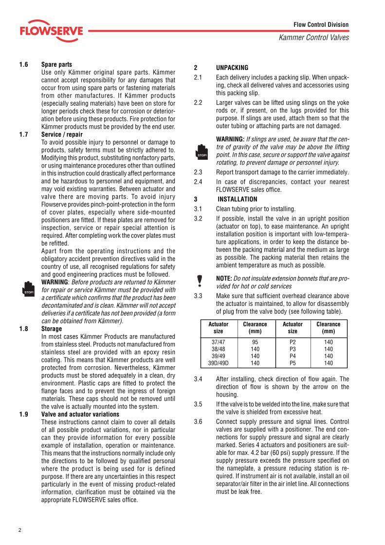
3.3 Make sure that sufficient overhead clearance abovethe actuator is maintained, to allow for disassemblyof plug from the valve body (see following table).
3.4 After installing, check direction of flow again. Thedirection of flow is shown by the arrow on thehousing.
3.5 If the valve is to be welded into the line, make sure thatthe valve is shielded from excessive heat.
3.6 Connect supply pressure and signal lines. Controlvalves are supplied with a positioner. The end con-nections for supply pressure and signal are clearlymarked. Series 4 actuators and positioners are suit-able for max. 4.2 bar (60 psi) supply pressure. If thesupply pressure exceeds the pressure specified onthe nameplate, a pressure reducing station is re-quired. If instrument air is not available, install an oilseparator/air filter in the air inlet line. All connectionsmust be leak free.
Actuator Clearance Actuator Clearancesize (mm) size (mm)
37/47 95 P2 14038/48 140 P3 14039/49 140 P4 140
39D/49D 140 P5 140
1.6 Spare partsUse only Kämmer original spare parts. Kämmercannot accept responsibility for any damages thatoccur from using spare parts or fastening materialsfrom other manufactures. If Kämmer products(especially sealing materials) have been on store forlonger periods check these for corrosion or deterior-ation before using these products. Fire protection forKämmer products must be provided by the end user.
1.7 Service / repairTo avoid possible injury to personnel or damage toproducts, safety terms must be strictly adhered to.Modifying this product, substituting nonfactory parts,or using maintenance procedures other than outlinedin this instruction could drastically affect performanceand be hazardous to personnel and equipment, andmay void existing warranties. Between actuator andvalve there are moving parts. To avoid injuryFlowserve provides pinch-point-protection in the formof cover plates, especially where side-mountedpositioners are fitted. If these plates are removed forinspection, service or repair special attention isrequired. After completing work the cover plates mustbe refitted.Apart from the operating instructions and theobligatory accident prevention directives valid in thecountry of use, all recognised regulations for safetyand good engineering practices must be followed.WARNING: Before products are returned to Kämmerfor repair or service Kämmer must be provided witha certificate which confirms that the product has beendecontaminated and is clean. Kämmer will not acceptdeliveries if a certificate has not been provided (a formcan be obtained from Kämmer).
1.8 StorageIn most cases Kämmer Products are manufacturedfrom stainless steel. Products not manufactured fromstainless steel are provided with an epoxy resincoating. This means that Kämmer products are wellprotected from corrosion. Nevertheless, Kämmerproducts must be stored adequately in a clean, dryenvironment. Plastic caps are fitted to protect theflange faces and to prevent the ingress of foreignmaterials. These caps should not be removed untilthe valve is actually mounted into the system.
1.9 Valve and actuator variationsThese instructions cannot claim to cover all detailsof all possible product variations, nor in particularcan they provide information for every possibleexample of installation, operation or maintenance.This means that the instructions normally include onlythe directions to be followed by qualified personalwhere the product is being used for is definedpurpose. If there are any uncertainties in this respectparticularly in the event of missing product-relatedinformation, clarification must be obtained via theappropriate FLOWSERVE sales office.
STOP!
STOP!
3
Flow Control Division
Kammer Control Valves
4 QUICK CHECK / MAINTENANCE
4.1 QUICK CHECK
Before operating, check the valve as follows:4.1.1 Open and close the valve, and observe the movement
of the actuator stem. The movement must be smoothand linear.
4.1.2 Check for maximum stroke through change of signal(for pneumatic positioners, 0.2 - 1.0 bar or corre-sponding split-range values; for IP positioners, 4-20or 0-20 mA).
4.1.3 Check all air connections for leaks.4.1.4 Tighten packing nut (see table 1).
NOTE: An excessively tightened gland nut can causeexcessive packing wear and can hinder the free move-ment of the plug stem.
4.1.5 Check fail-safe position. To do this, close supplypressure and observe whether the valve opens orcloses as defined.
4.1.6 After use at fluctuating temperatures, re-tighten allbolt connections and check for leaks.
4.2 Maintenance
Check valves for correct functioning at regular inter-vals (at least once every 6 months) as follows. Thischeck can be made when installed and in manycases without interrupting production. If internal de-fects are suspected, see section „Disassembly andAssembly of Valve“.
4.2.1 Examine gaskets for leaks and if necessary re-tightenbolts (see Fig. 1).
4.2.2 Check bellows gasket and test connection - if present- for external leaks.
4.2.3 Check valve for damage caused by corrosive residuesor corrosive vapours.
4.2.4 Clean valves and repaint as necessary.Warning: To prevent a buildup of electrostatic chargeclean the actuator/valve with a damp cloth only.
4.2.5 Check gland nut for correct torque (see table 1).
NOTE: An excessively tightened gland nut can causeexcessive packing wear and can hinder the free move-ment of the plug stem.
4.2.6 If possible, open and close valve and check formaximum stroke and smooth movement of the plugstem. Irregular movement of the plug stem mayindicate internal defects.NOTE: With graphite packing, irregular movement ofthe plug stem is normal.
WARNING: Keep hands, hair, clothing, etc. away fromall moving parts. Failure to do so can lead to seriousinjury.
4.2.7 Check all accessories for firm seating.4.2.8 If possible, close supply pressure and check the fail-
safe position.4.2.9 Check stem boot for wear.4.2.10 Check actuator for leaks. To do this, spray housing,
air connections and plug stem guide with leak sprayand check for any bubble formation.
4.2.11 Clean plug stem.4.2.12 Check air filter, if present, and if necessary replace
insert.Note:For further information regarding service andmaintenance please contact your nearest FLOWSERVEoffice.DANGER: On actuators with aluminium cases theactuator springs must be renewed with original spareparts every 10 years or after 50.000 operating hourswhich ever occurs first.
TorqueThread PTFE GrafoilM20 x 1,5 1 3M30 x 1,5 6 15M38 x 1,5 15 35M45 x 1,5 17 40
Table 1
STOP!
STOP!
4
Flow Control Division
Kammer Control Valves
5 Method of operation (actuators with integral Kämmer positioner)
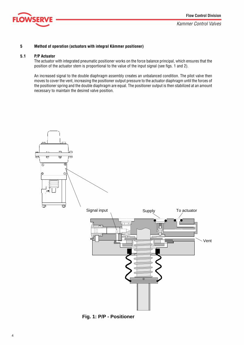
5.1 P/P ActuatorThe actuator with integrated pneumatic positioner works on the force balance principal, which ensures that theposition of the actuator stem is proportional to the value of the input signal (see figs. 1 and 2).
An increased signal to the double diaphragm assembly creates an unbalanced condition. The pilot valve thenmoves to cover the vent, increasing the positioner output pressure to the actuator diaphragm until the forces ofthe positioner spring and the double diaphragm are equal. The positioner output is then stabilized at an amountnecessary to maintain the desired valve position.
Signal input Supply To actuator
Vent
Fig. 1: P/P - Positioner
5
Flow Control Division
Kammer Control Valves
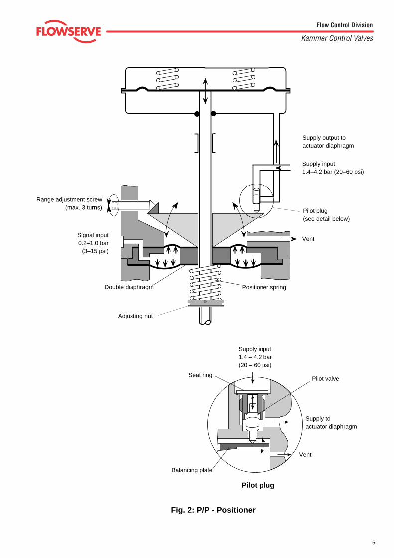
Pilot valve
Supply toactuator diaphragm
Vent
Pilot plug
Balancing plate
Seat ring
Supply input1.4 – 4.2 bar(20 – 60 psi)
Double diaphragm
Pilot plug(see detail below)
Supply output toactuator diaphragm
Supply input1.4–4.2 bar (20–60 psi)
Vent
Positioner spring
Range adjustment screw(max. 3 turns)
Signal input0.2–1.0 bar
(3–15 psi)
Fig. 2: P/P - Positioner
Adjusting nut
6
Flow Control Division
Kammer Control Valves
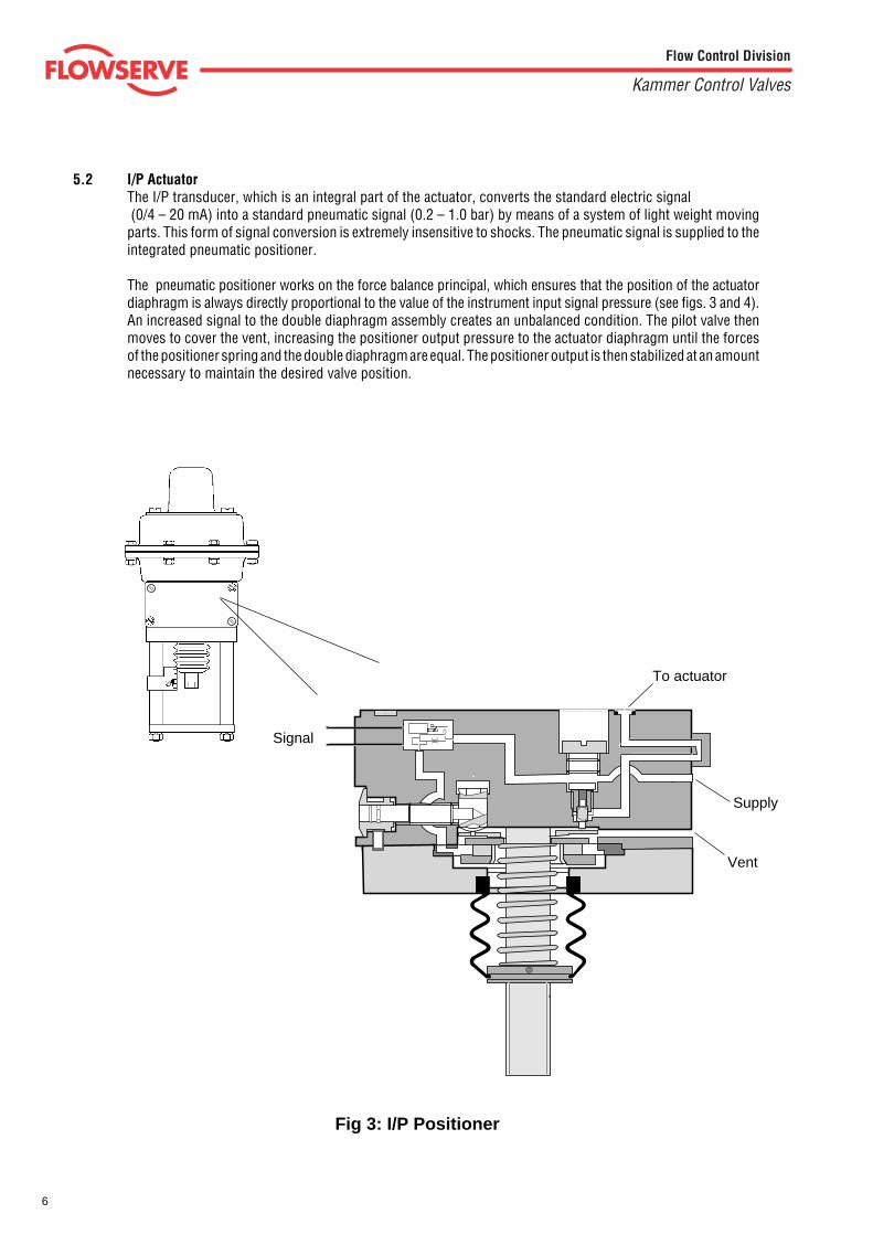
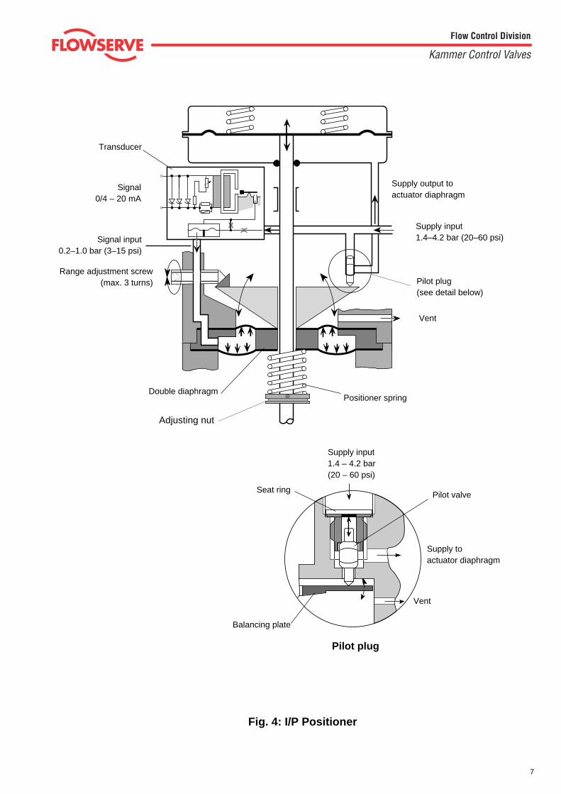
5.2 I/P ActuatorThe I/P transducer, which is an integral part of the actuator, converts the standard electric signal (0/4 – 20 mA) into a standard pneumatic signal (0.2 – 1.0 bar) by means of a system of light weight movingparts. This form of signal conversion is extremely insensitive to shocks. The pneumatic signal is supplied to theintegrated pneumatic positioner.
The pneumatic positioner works on the force balance principal, which ensures that the position of the actuatordiaphragm is always directly proportional to the value of the instrument input signal pressure (see figs. 3 and 4).An increased signal to the double diaphragm assembly creates an unbalanced condition. The pilot valve thenmoves to cover the vent, increasing the positioner output pressure to the actuator diaphragm until the forcesof the positioner spring and the double diaphragm are equal. The positioner output is then stabilized at an amountnecessary to maintain the desired valve position.
Signal
Fig 3: I/P Positioner
Vent
To actuator
Supply
7
Flow Control Division
Kammer Control Valves
Positioner spring
Pilot valve
Supply toactuator diaphragm
Vent
Pilot plug
Double diaphragm
Balancing plate
Seat ring
Supply input1.4 – 4.2 bar(20 – 60 psi)
Signal0/4 – 20 mA
Range adjustment screw(max. 3 turns)
Signal input0.2–1.0 bar (3–15 psi)
Vent
Pilot plug(see detail below)
Supply input1.4–4.2 bar (20–60 psi)
Supply output toactuator diaphragm
Transducer
Fig. 4: I/P Positioner
Adjusting nut
8
Flow Control Division
Kammer Control Valves
Series 47 / 48 / 49(without positioner)
1
2
2
4
1
3
Series 37 / 38 / 39(with positioner)
Fig. 5
9
Flow Control Division
Kammer Control Valves
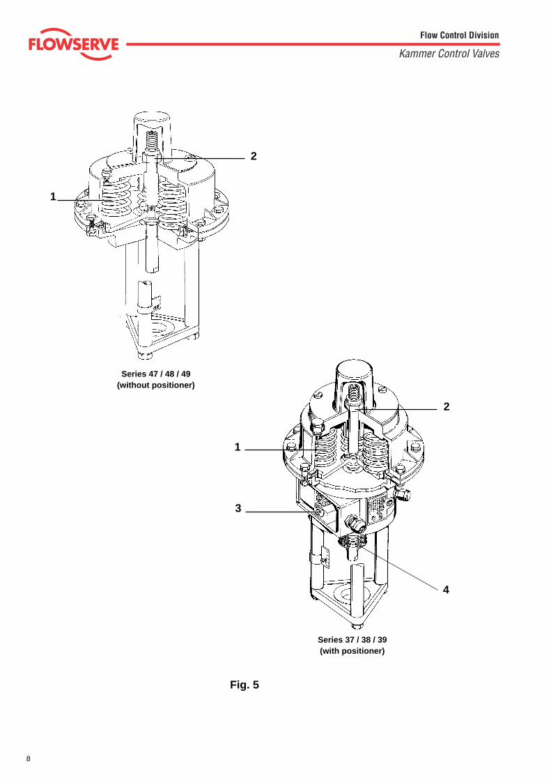
5.3 Actuator Springs - (fig. 5 pos. 1)Different actuator spring sets are available depending on the actuator thrust requirements and the failposition of the actuator. The appropriate spring set can be chosen from the spare parts list.
5.4 Zero Adjustment Locknut - (fig. 5 pos. 2)The zero adjustment locknut is used as a mechanical stop so that the actuator just begins to travel whenthe desired signal is applied to the positioner.
5.5 Range Adjustment - (fig. 5 pos.3)(Actuator with positioner only)The actuator travel is adjusted by means of the range adjustment screw. Turn the range adjustment screwso that the actuator stem travels the required distance in response to the positioner input signal.
5.6 Positioner Spring - (fig. 5 pos. 4)(Actuator with positioner only)To change the signal range from full to split range the positioner spring must be changed.
Examples: from 3-15 psi to 3-9 psi or 9-15 psi from 4-20 mA to 4-12 mA or 12-20 mA
Notice that split ranging on electro-pneumatic actuator is also done by means of the positioner spring.
After removal of the spring boot and retaining ring on older actuators or by removing the boot, positionerspring adjustment nut on newer actuators, the spring can be replaced.
10
Flow Control Division
Kammer Control Valves
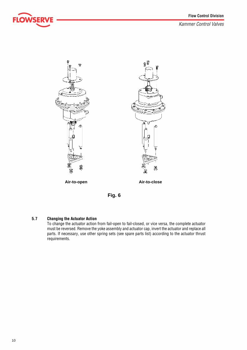
Air-to-open Air-to-close
Fig. 6
5.7 Changing the Actuator ActionTo change the actuator action from fail-open to fail-closed, or vice versa, the complete actuatormust be reversed. Remove the yoke assembly and actuator cap, invert the actuator and replace allparts. If necessary, use other spring sets (see spare parts list) according to the actuator thrustrequirements.

11
Flow Control Division
Kammer Control Valves
Fig. 7a
Fig. 7b
Connection "EXT"
O - RingGasket
Connection "EXT"
For positioner without "EXT" coveron the reverse side exchangeposition of gasket and O-ring.
"EXT" cover
O - Ring
Special O - Ring
For positioner with "EXT" cover on thereverse side exchange position ofO - ring and special O-ring.
5.8 External PipingWhen using solenoid valves (not NAMUR), lock-up valves, volume boosters, etc.; external piping is possiblewithout the need of additional parts. Solenoid valves to NAMUR-standard (modified) can be bolted directly ontothe positioner body.
Positioner without "EXT" cover on the reverse side:Exchange position of gasket and O - ring (Fig. 7a).Remove the plugs marked "EXT" from the positioner body and diaphragm case.Accessories can now be piped between the positioner and diaphragm case.
Positioner with "EXT" cover on the reverse side:Exchange the position of the O - ring and special O - ring in the "EXT" cover. (Fig. 7b)Remove the plugs marked "EXT" from the positioner body and diaphragm case.Accessories can now be piped between the positioner and diaphragm case.
12
Flow Control Division
Kammer Control Valves
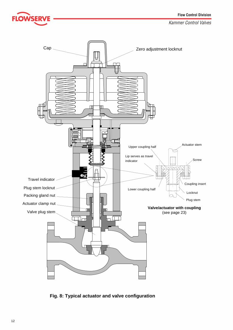
Valve plug stem
Actuator clamp nut
Packing gland nut
Plug stem locknut
Zero adjustment locknutCap
Lower coupling half
Actuator stem
Screw
Upper coupling half
Lip serves as travel
indicator
Valve/actuator with coupling(see page 23)
Plug stem
Coupling insert
Locknut
Travel indicator
Fig. 8: Typical actuator and valve configuration
13
Flow Control Division
Kammer Control Valves
6 GENERAL SERVICE INFORMATIONService to the actuator is best performed when the actuator is removed from the valve body.For the purpose of these instructions, consider the actuator as a separate subassembly with the proceduresdescribed in these instructions being performed on a bench. However, many service repairs and adjustmentscan be accomplished in the field while the actuator and valve body are still connected to each other.
6.2.1 Valve/actuator without coupling
6.2.1.1 Place the actuator assembly onto the valve bodysubassembly. At the same time, install the clamping nut,packing gland nut, plug stem locknuts, and the travel indi-cator disc.
6.2.1.2 "Air-to-open/fail-to-close" actuators only:
Rotate the actuator assembly clockwise, threading the ac-tuator stem onto the plug stem until the yoke plate justmakes contact with the bonnet flange, and the actuator isproperly aligned for installation.
NOTE: Ensure that the plug assembly is not rotated with theplug seated. This may cause irreparable damage to theseating faces.
"Air-to-close/fail-to-open" actuators only:
Lift the plug stem to the actuator stem. Thread the plug steminto the actuator stem so that the distance "plug in seat", to"plug raised", is approximately the distance of the specifiedstroke.
6.2.1.3 Tighten the clamping nut and the packing gland nut (seevalve service instructions for torque values).
6.2.1.4 Adjust the valve plug for seat off by threading the plug stemfurther into or out of the actuator stem.
NOTE: rotate the plug stem while the valve is in the closedposition. Open the valve first, make the adjustment while thevalve is open, and then close the valve to check for seat-off.
6.2.1.5 After final adjustments are made, lock the two stem nutsagainst the actuator stem and set the position of the travelindicator on the yoke rod.
6.2.2 Valve/actuator with coupling
6.2.2.1 Place actuator onto valve.
6.2.2.2 Screw on and tighten yoke rod nuts.
6.2.2.3 Fit the coupling screws finger tight.
6.2.2.4 Adjust the valve plug for seat off by threading the plug stemfurther into or out of the coupling insert.
NOTE: rotate the plug stem while the valve is in the closedposition. Open the valve first, make the adjustment while thevalve is open, and then close the valve to check for seat-off
6.2.2.5 After final adjustment tighten the coupling screws and setthe position of the travel indicator on the yoke rod.
6.1 REMOVING ACTUATOR FROM VALVE BODY
DANGER: Depressurise the line to atmospheric pressureand drain all fluids from the valve before working on theactuator. Failure to do so can cause serious injury.
For air-to-open actuators start with 6.1.1
For air-to-close actuators start with 6.1.2.1
6.1.1 Remove the valve cap and nameplate. Turn the zero adjust-ment locknut until it just makes contact with the actuatorspring case (this removes the spring force from the valveplug).
6.1.2 Valve/actuator without coupling
6.1.2.1 With a wrench, hold the actuator stem to prevent it fromrotating while using a second wrench to loosen the plugstem locknuts.
NOTE: If the actuator stem is rotated the diaphragm will betwisted and this may cause irreparable damage.
6.1.2.2 Loosen the packing gland nut and the actuator clamp nut.
6.1.2.3 Being sure not to turn the plug stem, rotate the actuatorassembly counterclockwise to disengage the actuator stemfrom the valve plug stem.
NOTE: Ensure that the plug assembly is not rotated with theplug seated. This may cause irreparable damage to theseating faces.
6.1.2.4 Lift the actuator assembly from the valve body subassembly.At the same time, remove the plug stem locknuts, the travelindicator disc, packing gland nut, and clamping nut.
6.1.3 Valve/actuator with coupling
6.1.3.1 With a wrench, hold the actuator stem to prevent it fromrotating while using a second wrench to loosen and removecoupling screws.
6.1.3.2 Remove the yoke rod nuts and lift actuator a s s e m b l yfrom the valve.
6.2 CONNECTING ACTUATOR TO VALVE BODY
General Notes:
• The actuator must be calibrated before connecting it to thevalve body. See section 3 "Calibration" of these instructions.
• All worn or damaged parts must be replaced. All parts to bereused should be cleaned for ease of reassembly.
14
Flow Control Division
Kammer Control Valves
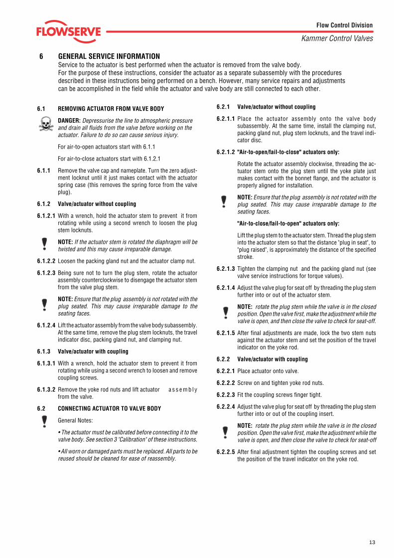
Fig. 9
12
15
14
17
16
13
1
3
72
456
8
910
11
Series 37 / 38 / 39(with positioner)
Series 47 / 48 / 49(without positioner)
1
2
15
Flow Control Division
Kammer Control Valves
7 ACTUATOR DISASSEMBLY and ASSEMBLY
7.1 ACTUATOR DISASSEMBLY
(refer to figs. 9 and 11)
NOTE: To help reassembly note or mark the rela-tionship between the parts to be disassembled.
7.1.1 Remove yoke plate (1) and yoke rods (2).
For actuators without positioner continue with7.1.5.
7.1.2 Actuators without adjustable positioner spring(see Fig. 9)
Remove the positioner spring boot (3), retainingring (4), seating washer (5), and positioner spring(6).
Actuators with adjustable positioner spring(see Fig. 15)
Loosen the set screw in the positioner springadjusting nut and remove the nut. Remove bootand positioner spring.
7.1.3 Loosen and remove the positioner cover screws(7), positioner cover (8), double diaphgram (9)and balancing plate (10).
7.1.4 Remove the positioner (11). All inner positionerparts are now accessible for replacement or main-tenance (for positioner details see figs. 10 and11).
7.1.5 Loosen and remove all case screws (12).
DANGER: Actuators with high thrust spring setsand/or actuators with 40 mm (1.5") stroke must beheld in a press to prevent possible injury whenremoving the case screws.
7.1.6 Unscrew the zero adjustment lock nut (13).
7.1.7 The spring case and diaphragm case can now beseparated, and the springs removed.
7.1.8 Holding the actuator stem, unscrew and removethe clamping nut (14) to service the actuatordiaphragm and diaphragm plate.
7.2 ACTUATOR ASSEMBLY
(refer to figs. 9 to 13)
7.2.1 Install the diaphragm and diaphragm plate on theactuator stem. Use Loctite® #242 on the threadedportion of the actuator stem where the clampingnut (14) is to be installed. Install and tighten theclamping nut, being sure not to kink the dia-phragm.
7.2.2 Place the spring set into the spring case so thatthey sit in the recessed area of the case (15).Smaller diameter springs are placed inside oflarger diameter springs.
7.2.3 Insert the actuator stem through the hole in thespring case (15).
7.2.4 Install the zero adjustment locknut (13) on theactuator stem and tighten it down fully to com-pressing the springs.
DANGER: A press must be used to compress thesprings when high thrust spring sets are installedor when actuator stroke is 40 mm.
7.2.5 Before inserting a new O-ring (16) in the dia-phragm case, pack the O-ring groove with a multi-temperature assembly paste
7.2.6 Replace the diaphragm gasket (17) and install thediaphragm case onto the spring case assembly.
7.2.7 Install and tighten all case screws (12), washersand nuts using a crisscross pattern.
Continued....

16
Flow Control Division
Kammer Control Valves
Double diaphragmFig. 13
Balancing plate assemblyFig. 12
Range adjustment pin
Balancing plate
Signal orifice
19
18
10
9
PositionerFig. 11
17
Flow Control Division
Kammer Control Valves
(7.4 Actuator assembly continued)
7.4.8 to 7.4.11 for actuator with positioner only.
7.2.8 Assemble the positioner using new O-rings, gas-kets and filters and install the positioner body (seefigs. 11).
7.2.9 Install the balancing plate (10) so that the smallhole fits over the plastic range adjustment pin (seefig.12), and the bevelled side faces the doublediaphragm (flat side to positioner).
7.2.10 Install the double diaphragm assembly (9) align-ing the small hole in the diaphragm with the holein the diaphragm ring and the signal orifice in thepositioner body (see fig. 13).
7.2.11 Actuator without adjustable positioner spring(see Fig 9)
Install the positioner cover (8), positioner coverscrews (7), positioner spring (6), seating ring (5),retaining ring (4), and positioner spring boot (3).
Actuator with adjustable positioner spring(see Fig 15)
Install the positioner cover, positioner coverscrews, positioner spring and positioner springboot. Thread adjusting nut onto actuator stem andadjust roughly using the gauge (lower edge ofadjusting nut the underside of positioner cover).
7.2.12 Refit yoke rods (2) and yoke plate (1).
The actuator is now ready to be calibrated.
7.3 POSITIONER SERVICE
The KÄMMER integral positioner is designed to be amaintenance free unit. However; moisture, oil and dirtentering the positioner can dampen its performance,which will cause the need for maintenance and repair.When this happens, remove all internal parts and cleanthem thoroughly. Replace all O-rings, filters and dam-aged parts, and reassemble the positioner body ac-cording to fig. 11.
Positioners with integral I/P transducers are moresensitive to contaminants than those without. There-fore, it is very important that all parts to be reused areextremely clean and dry.
I/P transducerTo remove the I/P transducer, disconnect the wiresfrom the terminal block and loosen the set screw (19)on the side of the positioner housing. The I/P trans-ducer can then be pulled from the front of the posi-tioner housing. The main cause of transducer mal-function is a polluted air supply. Filters are situated inthe input and output orifices of the transducer and arereadily accessible after removing the O-rings. Apartfrom the O-rings and filters the transducer contains nouser serviceable parts. The transducer is factory ad-justed to exactly 4 – 20 mA or 0 – 20 mA (documentedby a sticker on the transducer cover) and an attempt tofield calibrate is not recommended. For repair and/orcalibration the transducer assembly should be re-turned to Kämmer.
18
Flow Control Division
Kammer Control Valves
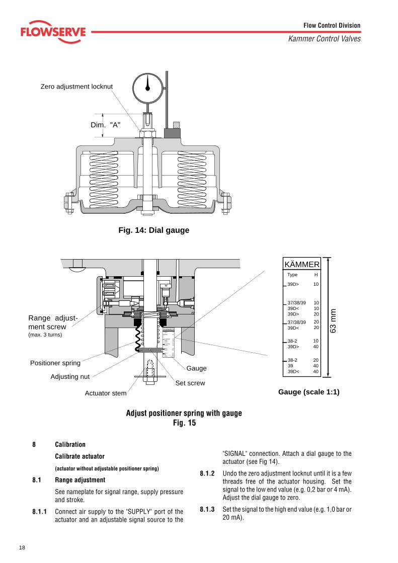
Fig. 14: Dial gauge
Adjust positioner spring with gaugeFig. 15
KÄMMER
39D>
37/38/3939D<39D>
37/38/3939D<
38-239D>
38-23939D<
10
101020
2020
1040
204040
Type H
Positioner spring
Adjusting nut
Actuator stem
Range adjust-ment screw(max. 3 turns)
Gauge
Set screwGauge (scale 1:1)
Dim. "A"
8 Calibration
Calibrate actuator
(actuator without adjustable positioner spring)
8.1 Range adjustment
See nameplate for signal range, supply pressureand stroke.
8.1.1 Connect air supply to the "SUPPLY" port of theactuator and an adjustable signal source to the
"SIGNAL" connection. Attach a dial gauge to theactuator (see Fig 14).
8.1.2 Undo the zero adjustment locknut until it is a fewthreads free of the actuator housing. Set thesignal to the low end value (e.g. 0,2 bar or 4 mA).Adjust the dial gauge to zero.
8.1.3 Set the signal to the high end value (e.g. 1,0 bar or20 mA).
Zero adjustment locknut
KÄMMER
39D>
37/38/3939D<39D>
37/38/3939D<
38-239D>
38-23939D<
10
101020
2020
1040
204040
Type H
63 m
m
19
Flow Control Division
Kammer Control Valves
8.1.4 Using the range adjusting screw set the actuator to fullstroke + 1.5 mm (e.g. stroke 20 + 1.5 mm = 21.5 mm).
8.1.5 Make adjustment with the range adjusting screw asrequired until desired stroke is obtained
8.2 Zero adjustment
3.2.1 The zero adjustment can only be set after the finalrange adjustment has been made.
8.2.2 Maintain the low end signal (e.g. 0.2 bar or 4 mA) andturn the zero adjustment locknut until it just makescontact with the actuator housing.
8.3 Calibrate actuator
(actuator with adjustable positioner spring)
See nameplate for signal range, supply pressure andstroke.
8.3.1 Connect air supply to the "SUPPLY" port of the actua-tor and an adjustable signal source to the "SIGNAL"connection. Attach a dial gauge to the actuator (see Fig14).
8.3.2 Undo the zero adjustment locknut until it is a fewthreads free of the actuator housing.
Loosen the set screw and thread the adjusting nut onthe actuator stem until it's lower face is in alignmentwith the appropriate type designation on the gauge.
8.3.3 Set the signal to the low end value (e.g. 0.2 bar or 4mA). Adjust the dial gauge to zero.
8.3.4 Set the signal to the high end value (e.g. 1.0 bar or 20mA).
8.3.5 Using the range adjusting screw set the actuator to fullstroke + 1.5 mm (e.g. stroke 20 + 1.5 mm = 21.5 mm).
8.3.6 Set signal and dial gauge to zero.
8.3.7 Set the signal to the low end value. Adjust the posi-tioner spring adjusting nut to compress/decompressthe positioner spring until the actuator stem rises 1.5mm.
8.3.8 Set the signal to the high end value (e.g. 1.0 bar or 20mA). Using the range adjusting screw set the actuatorto full stroke + 1.5 mm (e.g. stroke 20 + 1.5 mm = 21.5mm).
8.3.9 Repeat adjustments 8.3.3 to 8.3.8 until both adjust-ments are correct.
8.3.10 Set signal to zero and tighten the set screw in theadjusting nut. Set the signal to the low end value. Setthe dial gauge to zero and tighten zero adjustmentlocknut, until the dial gauge pointer just moves (nutcontacts the actuator housing) and then a further 1/4turn ( around 3/10 mm pretension).
8.3.11 Check all adjustments for correctness.
8.4 Calibrate actuator/valve
8.4.1 Connect air supply to the "SUPPLY" port of the actua-tor and an adjustable signal source to the "SIGNAL"connection. Undo the zero adjustment locknut until itis a few threads free of the actuator housing. Attach adial gauge to the actuator and set it to zero.
8.4.2 Determine the instrument signal at which the plugshould begin moving off the seat and apply that signalto the valve. If the plug stem does not begin to moveat the predetermined signal, adjust the signal tomidrange until the plug is off the seat, loosen the plugstem locknut and turn the plug stem in or out of theactuator stem.
For example, if the plug begins to move at a lowersignal than the predetermined one, turn the plug stemout of the actuator stem. If the plug begins to move ata higher signal than the predetermined one, turn theplug into the actuator stem. Repeat this process untilthe actuator is calibrated as required and re-tightenthe plug stem locknut. Adjust the zero adjustmentlocknut until it is 2 mm off the actuator and replace theactuator cap.
NOTE: Do not turn the plug stem when the plug isseated; otherwise, the plug and seat ring may bedamaged.
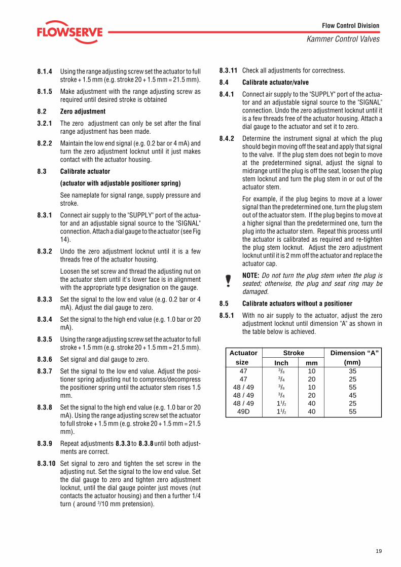
8.5 Calibrate actuators without a positioner
8.5.1 With no air supply to the actuator, adjust the zeroadjustment locknut until dimension "A" as shown inthe table below is achieved.
Actuator Stroke Dimension “A”
Inch mm47 3/8 10 3547 3/4 20 25
48 / 49 3/8 10 5548 / 49 3/4 20 4548 / 49 11/2 40 25
49D 11/2 40 55
size (mm)
20
Flow Control Division
Kammer Control Valves
47 48 49 49D 37 38 39 39D IP-37 IP-38 IP-39 IP-39D
Diaphragm area cm2 80 200 500 2 x 500 80 200 500 2 x 500 80 200 500 2 x 500
Thrust max. kg 160 400 1000 2000 160 400 1000 2000 160 400 1000 2000
Stroke mm 10/20 10/20 10/20/40 10/20/40 10/20 10/20 10/20/40 10/20/40 10/20 10/20 10/20/40 10/20/40
Time at stroke10 mm s* 0.1 0.25 0.5 1 0.5 1 2.5 5 0.5 1 2.5 5
20 mm s* 0.2 0.5 1 2 1 2 5 10 1 2 5 10
40 mm s* – – 2 4 – – 10 20 – – 10 20
Signal range 3 – 15 psi 3 – 15 / 3 – 9 / 9 – 15 psi 0/4 – 20, 4 – 12, 12 – 20 mA or rev.
0.2 – 1.0 bar 0.2 – 1.0 / 0.2 – 0.6 / 0.6 – 1.0 bar –
20 – 60 kPa 20 – 100 / 20 – 60 / 60 – 100 kPa –
Input resistance – – 260/170 Ohm**
Inductivity / Capacitance – – negligible (≈0)
Spring range see appropriate spare parts list see appropriate spare parts list see appropriate spare parts list
Supply pressure 20 – 60 psi 20 – 60 psi 20 – 60 psi
1.4 – 4.2 bar 1.4 – 4.2 bar 1.4 – 4.2 bar
140 – 420 kPa 140 – 420 kPa 140 – 420 kPa
Accuracy – ±1% = 1%
Hysteresis – < 1% = 1%
Operating sensitivity – – = 0.1%
Amplification factor – 50 50
Supply pressure influence – 0.4% / 0.1 bar 0.4% / 0.1 bar
Air consumption at 1,4 bar – 0.6 Nm3 / h 0.6 Nm3 / h
Electrical protection – – EEx ia C T6, PTB No. Ex-93.C. 2104X
Suitable for connection to intrinsical
safe circuits with I max.
= 60 mA (T6) thru 150 mA (T4)
Housing protection – – IP 54
Allowable ambient temp. – 30 to + 80 °C (-22 to +176° F)
Actuator action air-to-open / air-to-close, reversible
Installation position optional
Air supply dry and oil-free (instrument air)
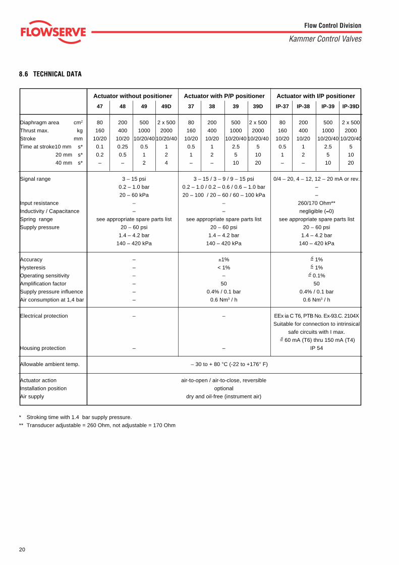
8.6 TECHNICAL DATA
Actuator without positioner Actuator with P/P positioner Actuator with I/P positioner
<
<
<
<
* Stroking time with 1.4 bar supply pressure.
** Transducer adjustable = 260 Ohm, not adjustable = 170 Ohm
21
Flow Control Division
Kammer Control Valves
---
14,0 / 2,2 x 56,7-
14,0 / 2,2 x 56,714,0 / 2,2 x 56,714,0 / 2,2 x 56,7
-19,7 / 2,2 x 60,0
-19,7 / 2,2 x 60,019,7 / 2,2 x 60,019,7 / 2,2 x 60,0
---
26,5 / 4,0 x 76,7-
26,5 / 4,0 x 76,726,5 / 4,0 x 76,726,5 / 4,0 x 76,7
---
26,5 / 3,6 x 80-
26,5 / 3,6 x 8026,5 / 3,6 x 8026,5 / 3,6 x 80
--
43 / 6,3 x 133,3-
43 / 6,3 x 133,343 / 6,3 x 133,343 / 6,3 x 133,3
--
45,7 / 5,25 x 148-
45,7 / 5,25 x 14845,7 / 5,25 x 14845,7 / 5,25 x 148
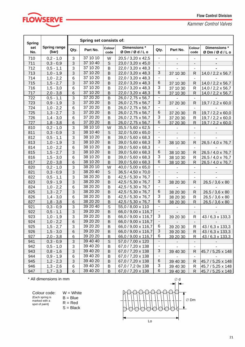
Colour code: W = WhiteB = BlueR = RedS = Black
(Each spring ismarked with aspot of paint)
710711712713714715716717722723724725726727810811812813814815816817820821822823824825826827921922923924925926927941942943944945946947
Spring set consists of:
Dimensions *Ø Dm / Ø d / L o
---R-RRR-R-RRR---R-RRR---R-RRR--R-RRR--R-RRR
Qty.
---3-636-3-636---3-636---3-636--3-636--3-636
20,5 / 3,20 x 42,523,0 / 3,20 x 45,022,0 / 3,20 x 48,322,0 / 3,20 x 48,322,0 / 3,20 x 48,322,0 / 3,20 x 48,322,0 / 3,20 x 48,322,0 / 3,20 x 48,326,0 / 2,75 x 56,726,0 / 2,75 x 56,726,0 / 2,75 x 56,726,0 / 2,75 x 56,726,0 / 2,75 x 56,726,0 / 2,75 x 56,735,5 / 5,60 x 62,532,0 / 5,00 x 65,039,0 / 5,60 x 68,339,0 / 5,60 x 68,339,0 / 5,60 x 68,339,0 / 5,60 x 68,339,0 / 5,60 x 68,339,0 / 5,60 x 68,340,0 / 5,00 x 65,036,5 / 4,50 x 70,042,5 / 5,30 x 76,742,5 / 5,30 x 76,742,5 / 5,30 x 76,742,5 / 5,30 x 76,742,5 / 5,30 x 76,742,5 / 5,30 x 76,755,0 / 8,00 x 11066,0 / 9,00 x 116,766,0 / 9,00 x 116,766,0 / 9,00 x 116,766,0 / 9,00 x 116,766,0 / 9,00 x 116,766,0 / 9,00 x 116,757,0 / 7,00 x 12067,0 / 7,20 x 13867,0 / 7,20 x 13867,0 / 7,20 x 13867,0 / 7,20 x 13867,0 / 7,2 0x 13867,0 / 7,20 x 138
Dimensions *Ø Dm / Ø d / L o
WSBBBBBBBBBBBBWSBBBBBBWSBBBBBBSBBBBBBSBBBBBB
37 10 1037 10 4037 10 2037 10 2037 10 2037 10 2037 10 2037 10 2037 20 2037 20 2037 20 2037 20 2037 20 2037 20 2038 10 1038 10 4038 10 2038 10 2038 10 2038 10 2038 10 2038 10 2038 20 1038 20 4038 20 2038 20 2038 20 2038 20 2038 20 2038 20 2039 20 4039 20 2039 20 2039 20 2039 20 2039 20 2039 20 2039 40 4039 40 2039 40 2039 40 2039 40 2039 40 2039 40 20
Qty.
33336366336366333363663333636633363663336366
Spring set No.
Part No.
---
37 10 30-
37 10 3037 10 3037 10 30
-37 20 30
-37 20 3037 20 3037 20 30
---
38 10 30-
38 10 3038 10 3038 10 30
---
38 20 30-
38 20 3038 20 3038 20 30
--
39 20 30-
39 20 3039 20 3039 20 30
--
39 40 30-
39 40 3039 40 3039 40 30
Colourcode
Colourcode
Spring range(bar) Part No.
0,2 - 1,00,3 - 0,90,5 - 1,11,0 - 1,91,0 - 2,21,5 - 2,71,5 - 3,02,0 - 3,80,5 - 1,10,9 - 1,91,0 - 2,21,3 - 2,71,4 - 3,01,8 - 3,80,2 - 1,00,3 - 0,90,5 - 1,11,0 - 1,91,0 - 2,21,5 - 2,71,5 - 3,02,0 - 3,80,2 - 1,00,3 - 0,90,5 - 1,10,9 - 1,91,0 - 2,21,3 - 2,71,4 - 3,01,8 - 3,80,3 - 0,90,5 - 1,11,0 - 1,91,0 - 2,21,5 - 2,71,5 - 3,02,0 - 3,80,3 - 0,90,5 - 1,00,8 - 1,60,9 - 1,91,2 - 2,31,3 - 2,61,7 - 3,3
* All dimensions in mm
Lo
∅ Dm
∅ d

22
Flow Control Division
Kammer Control Valves
Part - No. Spring range Spring range Stroke Lo ø Dm ød
[bar] [mA] [mm] [mm] [mm] [mm]
0 36 00 10 00 0.2 - 1.0 0/4 - 20 10 39.75 20.0 2.0
0 36 00 20 00 0.2 - 0.6 0/4 - 10/12 10 42.5 20.0 1.6
0 36 00 30 00 0.2- 1.0 0.6 - 1.0 0/4 - 20 10/12 - 20 20 10 55.5 19.5 1.7
0 36 00 40 00 0.2 - 0.6 0/4 - 10/12 20 60.0 22.5 1.5
0 36 00 50 00 0.2- 1.0 0.6 - 1.0 0/4 - 20 10/12 - 20 40 20 85.0 20.5 1.6
0 36 00 60 00 0.2 - 0.6 0/4 - 10/12 40 100 21.0 1.4
0 36 00 70 00 0.6 - 1.0 10/12 - 20 40 140.0 18.7 1.4
Lo
∅ Dm
∅ d
Positioner spring
23
Flow Control Division
Kammer Control Valves
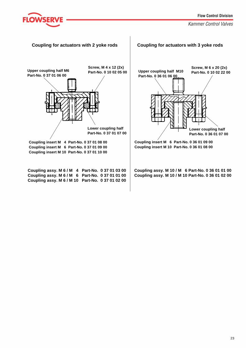
Lower coupling halfPart-No. 0 37 01 07 00
Lower coupling halfPart-No. 0 36 01 07 00
Coupling insert M 4 Part-No. 0 37 01 08 00Coupling insert M 6 Part-No. 0 37 01 09 00Coupling insert M 10 Part-No. 0 37 01 10 00
Coupling assy. M 10 / M 6 Part-No. 0 36 01 01 00Coupling assy. M 10 / M 10 Part-No. 0 36 01 02 00
Screw, M 6 x 20 (2x)Part-No. 0 10 02 22 00
Screw, M 4 x 12 (2x)Part-No. 0 10 02 05 00
Coupling for actuators with 2 yoke rods Coupling for actuators with 3 yoke rods
Coupling insert M 6 Part-No. 0 36 01 09 00Coupling insert M 10 Part-No. 0 36 01 08 00
Upper coupling half M10Part-No. 0 36 01 06 00
Upper coupling half M6Part-No. 0 37 01 06 00
Coupling assy. M 6 / M 4 Part-No. 0 37 01 03 00Coupling assy. M 6 / M 6 Part-No. 0 37 01 01 00Coupling assy. M 6 / M 10 Part-No. 0 37 01 02 00
24
Flow Control Division
Kammer Control Valves
All data subject to change without notice©03.2002 Flowserve Corporation. Flowserve and Kämmer are trademarks of Flowserve Corporation
Regional Headquarters
Flowserve Flowserve FlowserveManderscheidtstr. 19 1350 N. Mt. Springs Prkwy. 12 Tuas Avenue 2045141 Essen Springville, UT 84663Germany USA Singapore 638824Telephone: +49 (0) 201 8919 5 Telephone: +1 801 489 8611 Telephone: +65 862 3332Facsimile: +49 (0) 201 8919 662 Facsimile: +1 801 489 3719 Facsimile: +65 862 4940
Main Sales Offices (Europa, Middle east, Africa)
Flowserve Flowserve Flowserve Flowservevon-Braun-Straße 19a 12, av. du Québec Station Road Allee du Quartz 148681 Ahaus 91965, Courtaboeuf Cedex Pershore, Worcestershire CH-2300 La-Chaux-de FondsGermany France England WR102BZ SwitzerlandTelephone: +49 (0) 2561 6860 Telephone: +33 (0) 1 60 923 251 Telephone: +44 (0) 1386 55 45 51 Telephone: +41 (0) 32 925 9700Facsimile: +49 (0) 2561 68648 Facsimile: +33 (0) 1 60 923 299 Facsimile: +44 (0) 1386 55 49 68 Facsimile: +41 (0) 32 926 5422
Flowserve FlowserveCnr. Bismit and Granier Str. C/O Saleh & Abdulaziz AbahsainJet Park Ext 3 P.O. Box 209Boksburg1459 Gauteng Al Khobar 31952South Africa Saudi ArabiaTelephone: +27 397-3150 Telephone: 9663 857 3442Facsimile: +27 397-5300/01/02 Facsimile: 9663 859 5284