Embed Size (px)
Citation preview

Floor-mounted Induction unitsacb 30/35
installation, operation & Maintenance manual

www.dadanco.com
built on innovationacb 30 & 35
Active Chilled Beam Models ACB30 & ACB35 are designed for installation in the ceiling space with down air discharge through separate ceiling-mounted grilles. The induced room air is drawn from the return air
ceiling plenum.
unit constructionEach concealed ceiling plenum-mounted active chilled beam unit consists of:
• Primary air plenum with primary air nozzles• Round or Oval primary air inlet connection (1) (See Handings Configuration Key for available sizes)• Supply air discharge slot (2)• Condensate tray (3)• Secondary water coil (4)• 2 mounting brackets with 2 mounting holes each (5)• Mixing chamber• 2 or 4-pipe secondary water coil connection (6) (Connection can be configured as supply or re-
turn based on on-site pipework)• An identification label and commissioning chart
NOTE: The separate supply and return air grille is normally provided by others.NOTE: The location of the air and coil connections on each beam is determined by on-site personnel using the Handings Configuration Key on pages 7 & 8 and returning a filled out Unit Configuration schedule provided in the submittal package.
The installer is to provide the following:• Required secondary water piping and valves including
isolation valves, balancing valves, flow control zone valves and other valves/controls as specified.
• Primary air volume control balancing damper.• Low resistance supply and return air grilles.• Condensate drainage from the unit drain pan if specified.
(Unit supplied with removable capped drain connection)• All mounting hardware (threaded rods, nuts, etc.) and
primary air flexible ducting.• If the supply air slot is more than 1/4” away from the grille, an in-fill piece between the
unit and the supply air grille’s frame is required to provide a seal between the unit and the grille. If the units drain pan is to be piped to drain, the in-fill piece will raise the unit above the grille frame to allow a fall in the drain line to provide gravity draining.
• Any other items necessary to complete the installation.NOTE: Dadanco provides several accessories to complement your installation. Please reference the Accessories brochure or contact Dadanco for available accessories.
pre-installation

1
If units are not being installed immediately store in a well protected, dry, temperate location until they are ready for installation. Reference the beams drawing for the weight at each designed length. Please follow your on-site safety standards when lifting units and utilize caution when inserting the beams into the ceiling. When possible please use a cart to transport the beams.
Remember to wear proper personal protection equipment.
unit construction
acb35
acb30
SCHW
HHW
HHW
SCHW
1
3
4
2
5
6
SCHW
HHW
HHW
SCHW
5
1
2
3
4
6

www.dadanco.com
installation• Check the unit labeling to ensure that the proper unit
is being installed at each location (pictured).• Determine the orientation of the air and water
connections in relation to the site plan.• Check to ensure adequate clearance for the piping
and duct connections. • Check that the available ceiling space for the installation
of the unit is free of other services and structural members.
• Determine the position of the unit in the ceiling grid.• NOTE: The unit can be positioned with the water
coil facing toward the perimeter or interior of the conditioned space. When access is restricted near the perimeter, the unit should be installed with the coil facing the interior for improved service access.
• NOTE: Beams are designed to have (1) mounting bracket on each end of the unit with (2) mounting holes each. Ensure that each mounting bracket and mounting hole are utilized during installation.
Various wire hanging kits are available in the market with different fasteners and end fixings. The below instructions apply to the hanging kits available from Dadanco. If other kits are used, please refer to the manufacturer’s installation instructions.
Attach a trapeze fastener to each mounting bracket on the ACB unit with the plastic clips provided in each kit.
Secure each end fixing (stud or hanging loop) to the building structure.
Pass each cable through the trapeze fasteners, and adjust to the height to at least 2-3” above the grille position.
Once the ceiling grille is installed per manufacturers installation instructions, the chilled beam can be lowered into position by adjusting the cable lengths to as close to the top of the supply grille as possible. If the gap between the unit and the grille is 1/4” or less, no physical connection is needed between the discharge slot and the grille. If the gap is greater than 1/4”, a sheet metal connection piece must be fabricated.
Note: If drain pans are to be piped, connection pieces are typically needed to raise the unit high enough above the ceiling to allow for gravity draining.
wire hanging kit

2
ACB45
ACB45 ACB55
• Determine the position of the first under-slab ‘Unistrut’ 2 foot channel bracket in the slab above or a ceiling structural member. The first ‘Unistrut’ channel bracket should be positioned approximately the distance from the mounting brackets to the end of the unit and centered in relation to the width of the unit and its opening in the ceiling grid. Drill and secure the ‘Unistrut’ channel bracket to the slab above or ceiling member with 3/8” bolts.
• Install the second ‘Unistrut’ channel bracket length at a position parallel to and at the correct distance from the first channel bracket along the length of the unit, according to the distance between brackets of the unit. Drill and secure the ‘Unistrut’ channel bracket to the slab above or ceiling member with 3/8” bolts.
• Determine required length of 3/8” threaded rod between the ‘Unistrut’ channel brackets and unit mounting brackets. Rod length should be approximately the distance from the suspended T-Bar ceiling tile frame lip to the underside of the slab above, or ceiling members, less the height of the brackets from the bottom of the unit. This provides sufficient rod length to permit the unit to be raised and lowered without removing the hanging rods.
• Install (1) 3/8” flat washer, hex nut and ‘Unistrut’ fixture nut to the top end of each 3/8” threaded rod.
• Install (1) 3/8” hex nut and flat washer to the other end of the threaded rod.• Raise the unit into position above the ceiling grid frame, aligned to the ceiling grid opening. Install
3/8” flat washer and hex nut to the treaded rod at the underside of the unit mounting bracket to hold the rod loosely on the bracket. Do not fully tighten nuts at this time.
• Raise the position of the unit by tightening the lower hex nuts until the bottom lip of the unit is approximately 2-3” clear of the top of the suspended ceiling grid T-Bar frame.
• Once the T-bar grid has been installed, lower the unit into the T-Bar frame by turning the bottom hex nuts. Unit supply/return air grille must fit completely into the T-Bar frame as if it were a ceiling tile.
NOTE: Unit can be moved front to back in the slots of the mounting brackets and left to right along the ‘Unistrut’ channel bracket lengths to achieve proper alignment prior to tightening the fasteners. The unit must be supported from the ceiling slab/structural member. The unit weight should not be supported by the T-bar grid.
• Assure the unit is level and properly aligned in the T-Bar frame before tightening the mounting hardware.
• Tighten all 3/8” hex nuts once the unit is properly positioned and aligned in the T-Bar gridNOTE: The unit must be supported from the ceiling slab/structural member. The unit weight should not be supported by a T-bar grid or drywall ceilling.
• Tighten all 3/8” hex nuts once the unit is properly positioned and aligned.
Threaded rod method

www.dadanco.com
All Dadanco chilled beams come with 1/2” OD connections regardless of the water flow rates; therefore 1/2” flexible or piping hoses should be used to connect to the beams. Otherwise, reducers are required
• Once the beam has been successfully installed in the correct ceiling position, install all isolation, control and balancing valves according to the design drawings
• NOTE: Install all valves and make all connections per industry approved plumbing practices and local codes.
• Connect the secondary water coil inlet (s) and outlet (s) to the correct secondary water pipes. Refer to submittal drawings and/or labeling on the units to determine which coil connections are supply and return for chilled water and/or hot water.
NOTE: For 4-pipe coils, ensure that the chilled water connections are made to the chilled water circuit and the hot water connections are made to the hot water circuit. It is recommended that the unit be connected with readily removable pipe lengths and unions or flexible hoses to permit disconnection and removal of the unit should this be required.
• In preparing to make the secondary water (SCHW) piping connections to the coil, ensure that the piping is aligned with the coil connections. If threaded NPT coil connections are provided, use the correct tools to grip the flare nut and union and apply only sufficient force to make the joint. The use of excessive force could result in fracturing of the water pipes or their solder connections.
NOTE: Take care during this jointing process to ensure that the coil-piping alignment is maintained.• Insulate flexible hoses or pipe connections as per project specifications. It is strongly
recommended to insulate chilled water piping and hoses, especially on the supply-side, to prevent formation of condensate
water connections
primary air duct connection• Connect the air with either flexible or rigid duct to the primary air inlet connection and seal
airtight.• Primary air inter-connecting flexible duct should be a minimum of 3 feet straight or gradual
radius between the primary air duct and the primary air connection of the unit.NOTE: Avoid sharp bends in the primary air duct connection.NOTE: Install all ductwork and make all connections per industry approved practices and local codes.
• A primary air volume control balancing damper for adjusting the primary air flow during commissioning must be installed at the take-off from the main primary air duct.
NOTE: Do not install the primary air volume control balancing damper directly to the unit primary air inlet connection. There should be at least 3ft distance between the unit and the damper.
• Insulate the primary air inlet up to the primary air duct connection.• Check that all duct connections are properly sealed to ensure no air leakage.

3
• For secondary water flow commissioning, a suitable balancing valve should be installed in order to measure and adjust the secondary water flow to the designed/specified value. Adjust the balancing valve in order to achieve the specified water flow rate per unit, according to the unit schedule.
• For 2-Pipe Heating or Cooling systems, balance the water flow to the chilled water flow rate as specified.
NOTE: Coils are rated at 500PSI.
• To accurately commission the primary air flow to the unit, measure the static pressure in the primary air plenum through the commissioning sampling tube. To achieve this, remove the sealing plug from the commissioning sampling tube and connect the pressure-sensing instrument (Manometer) to the commissioning sampling tube.
NOTE: Do not attempt to measure the static pressure in the flexible duct connection. Measure only at the provided commissioning sampling tube for commissioning purposes.
• To obtain the designed primary air and total air flow rate, adjust the primary air volume balancing damper as necessary to obtain the primary air plenum pressure to achieve the specified/design primary air flow using the plenum pressure versus primary air flow curve supplied for each unit.
• Replace the plug to seal the primary air commissioning sampling tube on completion.NOTE: Do not attempt to confirm total supply air quantities using a balancing hood measurement method. The airflow from the unit is a low velocity, low pressure air stream that is often below the accuracy range of restriction imposing measurement hoods. Resistance imposing balancing hoods are not recommended for validating total air quantity.NOTE: Do not attempt to confirm the primary air flow quantity by conventional Pitot-traverse methods in the primary air ductwork. Low duct velocities and boundary layer measurement inaccuracies do not permit accurate measurements of duct velocities for primary air installations.
commissioningsecondary water commissioning
Primary air commissioning
maintenanceIn normal operating conditions the minimum required maintenance involves the secondary water coil, nozzles (and lint screen if provided), and consists of:
• Visual inspection of the secondary water coil, nozzles and lint screen (if provided). Vacuum as required.
• To remove dust wipe the unit grille with a dry cloth.• Clean or replace the lint screen as necessary.

Air Handing: A Coil Handing: A
Spigot Options: 4” Oval
Air Handing: A Coil Handing: B
Spigot Options: 4” Oval
Air Handing: B Coil Handing: A
Spigot Options: 4” Oval
Air Handing: B Coil Handing: B
Spigot Options: 4” Oval
Air Handing: E Coil Handing: B
Spigot Options: 4”,6”
Air Handing: E Coil Handing: A
Spigot Options: 4”,6”
Air Handing: D Coil Handing: B
Spigot Options: 4”,6”,8” Oval
Air Handing: D Coil Handing: A
Spigot Options: 4”,6”,8” Oval
www.dadanco.com
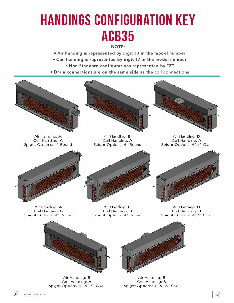
NOTE:
• Air handing is represented by digit 13 in the model number
• Coil handing is represented by digit 17 in the model number
• Non-Standard configurations represented by “Z”
• Drain connections are on the same side as the coil connections
handings configuration key acb30
Air Handing: A Coil Handing: A
Spigot Options: 4” Round
Air Handing: A Coil Handing: B
Spigot Options: 4” Round
Air Handing: B Coil Handing: A
Spigot Options: 4” Round
Air Handing: B Coil Handing: B
Spigot Options: 4” Round
Air Handing: E Coil Handing: B
Spigot Options: 4”,6”,8” Oval
Air Handing: E Coil Handing: A
Spigot Options: 4”,6”,8” Oval
Air Handing: D Coil Handing: B
Spigot Options: 4”,6” Oval
Air Handing: D Coil Handing: A
Spigot Options: 4”,6” Oval
www.dadanco.com
NOTE:
• Air handing is represented by digit 13 in the model number
• Coil handing is represented by digit 17 in the model number
• Non-Standard configurations represented by “Z”
• Drain connections are on the same side as the coil connections
handings configuration key acb35

www.dadanco.com 5
Seller warrants to the original Buyer only that the Products manufactured by Seller shall be free from defects in material or workmanship for a period of twelve (12) months measured from the date of ship-ment. The foregoing warranty will become void, and Seller will have no obligation whatsoever under this warranty, with respect to any of the following: (i) Products that are not used or maintained in a normal and proper manner, in accordance with any manuals and instructions that might be provided by Seller; (ii) Products that are modified, altered or repaired without the prior written approval of Sell-er; (iii) Buyer fails to make any payments when due under Section 3 or otherwise in the order or (iv) Products that are assigned, sold or transferred to an entity other than the Buyer. Seller will repair or replace at its option Products which upon Seller’s inspection it finds to be defective, based on claims made in writing to Seller by Buyer within a reasonable time after discovery and within the warranty period. Products alleged to be defective must be returned to Seller for repair or replacement, freight prepaid, within thirty (30) days of Buyer’s receipt of the return authorization number, obtained from Seller, which must be clearly marked on the outside of the return container Replacement compo-nents shall be shipped from Seller upon Buyer request and receipt of a valid purchase order number so the validity of the Warranty can be determined. Unless other-wise specified, replacement Products shall be Delivered to Buyer “Ex Works Seller’s factory” (Incoterms 2000). Any labor or equipment rental costs incurred in the dismantling and reassembly of the equipment into which the Products are installed shall be at Buyer’s sole expense. This warranty excludes Products furnished by the Seller but manufactured by another party. Such Products shall bear no warranties other than the warranties extended by and enforceable against the manufacturer thereof at the time of Delivery to Buyer (which
warranties Seller will furnish on Buyer’s written request), for the period stated in that warranty.
Notwithstanding the foregoing, to the extent that a Product or a component within a Product is deemed by Seller or, in the case of a component, the manufacturer of the component, to be obsolete,
such Product or component shall bear no warranty.
THE WARRANTY STATED HEREIN IS PERSONAL TO BUYER AND SELLER MAKES NO OTHER WAR-RANTIES OR REPRESENTATIONS WITH RESPECT TO THE PRODUCTS FURNISHED HEREUNDER AND DISCLAIMS ALL OTHER WARRANTIES, EXPRESS OR IMPLIED, INCLUDING WARRANTIES OF MERCHANTABILITY AND FITNESS FOR A PARTICULAR PURPOSE. THE ABOVE WARRANTY SHALL CONSTITUTE BUYER’S EXCLUSIVE REMEDY WITH RESPECT TO THE PRODUCTS FURNISHED
HEREUNDER.
If Buyer removes or permits anyone to remove any safety equipment or warning signs or fails to ob-serve any condition in this Section 14, or if any injury or damage is caused, in whole or in Product, by the end-user’s failure to comply with applicable federal, state or local safety requirements or Seller’s instructions as provided in Section 11 above, Seller shall have no obligation to Buyer, and Buyer shall indemnify and hold Seller harmless against any claims, loss or expense for injury or damage arising from the improper use of the Products or the equipment into which the Products are installed. Seller specifically disclaims any and all liability arising out of the operating of the equipment other than the
warranty liabilities to the original Buyer.
dadanco warranty

11
Made in USA • Made in USA •
The Luxton-Reed Center47 Westfield Industrial Park RoadWestfield, Massachusetts 01085
(413) 564-5657 [email protected]
Dadanco
Dadanco
DadancoHVAC
WWW.DADANCO.COM