Embed Size (px)
Citation preview
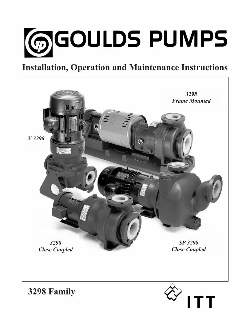
3298 Family
Installation, Operation and Maintenance Instructions
3298
Frame Mounted
3298
Close Coupled
V 3298
SP 3298
Close Coupled

FOREWORDThis manual provides instructions for the Installation, Operation, and Maintenance of the Goulds Model
3298 family of Magnetic Drive Process Pumps. This manual must be read and understood before
installation and start-up.
The design, materials, and workmanship incorporated in the construction of Goulds pumps makes them
capable of giving trouble-free service. The life and satisfactory service of any mechanical unit, however,
is enhanced and extended by correct application, proper installation, periodic inspection, condition
monitoring and careful maintenance. This instruction manual was prepared to assist operators in
understanding the construction and the correct methods of installing, operating, and maintaining these
pumps.
ITT - Goulds shall not be liable for physical injury, damage or delays caused by a failure to observe the
instructions for Installation, Operation, and Maintenance contained in this manual.
Warranty is valid only when genuine ITT - Goulds Pumps parts are used.
Use of the equipment on a service other than stated in the order could nullify the warranty, unless
written approval is obtained in advance from ITT - Goulds Pumps.
Supervision by an authorized ITT - Goulds representative is recommended to assure proper installation.
Additional manuals can be obtained by contacting your local ITT - Goulds representative, by calling
1-800-446-8537, or visiting our website at www.gouldspumps.com.
THIS MANUAL EXPLAINS
� Proper Installation
� Start-Up Procedures
� Operation Procedures
� Routine Maintenance
� Pump Overhaul
� Troubleshooting
� Ordering Spare or Repair Parts
4 3298 Family Rev. 5/08
3298 Family Rev. 5/08 5
2
4
7
5
6
8
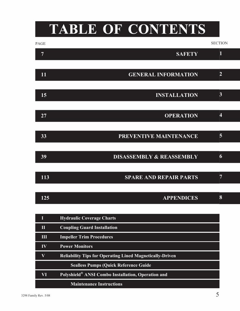
TABLE OF CONTENTSPAGE
7 SAFETY
11 GENERAL INFORMATION
15 INSTALLATION
27 OPERATION
33 PREVENTIVE MAINTENANCE
39 DISASSEMBLY & REASSEMBLY
113 SPARE AND REPAIR PARTS
125 APPENDICES
I Hydraulic Coverage Charts
II Coupling Guard Installation
III Impeller Trim Procedures
IV Power Monitors
V Reliability Tips for Operating Lined Magnetically-Driven
Sealless Pumps (Quick Reference Guide
VI Polyshield®
ANSI Combo Installation, Operation and
Maintenance Instructions
SECTION
1
3

6 3298 Family Rev. 5/08

S-1
IMPORTANT SAFETY NOTICE
To: Our Valued Customers
User safety is a major focus in the design of our products. Following the precautions outlined in this manual will minimize your risk of injury.
ITT Goulds pumps will provide safe, trouble-free service when properly installed, maintained, and operated.
Safe installation, operation, and maintenance of ITT Goulds Pumps equipment are an essential end user responsibility. This Pump Safety Manual identifies specific safety risks that must be considered at all times during product life. Understanding and adhering to these safety warnings is mandatory to ensure personnel, property, and/or the environment will not be harmed. Adherence to these warnings alone, however, is not sufficient — it is anticipated that the end user will also comply with industry and corporate safety standards. Identifying and eliminating unsafe installation, operating and maintenance practices is the responsibility of all individuals involved in the installation, operation, and maintenance of industrial equipment.
Please take the time to review and understand the safe installation, operation, and maintenance guidelines outlined in this Pump Safety Manual and the Instruction, Operation, and Maintenance (IOM) manual. Current manuals are available at www.gouldspumps.com/literature_ioms.html or by contacting your nearest Goulds Pumps sales representative.
These manuals must be read and understood before installation and start-up.
For additional information, contact your nearest Goulds Pumps sales representative or visit our Web site at www.gouldspumps.com.
S-2
SAFETY WARNINGS
Specific to pumping equipment, significant risks bear reinforcement above and beyond normal safety precautions.
WARNING
A pump is a pressure vessel with rotating parts that can be hazardous. Any pressure vessel can explode, rupture, or discharge its contents if sufficiently over pressurized causing death, personal injury, property damage, and/or damage to the environment. All necessary measures must be taken to ensure over pressurization does not occur.
WARNING
Operation of any pumping system with a blocked suction and discharge must be avoided in all cases. Operation, even for a brief period under these conditions, can cause superheating of enclosed pumpage and result in a violent explosion. All necessary measures must be taken by the end user to ensure this condition is avoided.
WARNING
The pump may handle hazardous and/or toxic fluids. Care must be taken to identify the contents of the pump and eliminate the possibility of exposure, particularly if hazardous and/or toxic. Potential hazards include, but are not limited to, high temperature, flammable, acidic, caustic, explosive, and other risks.
WARNING
Pumping equipment Instruction, Operation, and Maintenance manuals clearly identify accepted methods for disassembling pumping units. These methods must be adhered to. Specifically, applying heat to impellers and/or impeller retaining devices to aid in their removal is strictly forbidden. Trapped liquid can rapidly expand and result in a violent explosion and injury.
ITT Goulds Pumps will not accept responsibility for physical injury, damage, or delays caused by a failure to observe the instructions for installation, operation, and maintenance contained in this Pump Safety Manual or the current IOM available at www.gouldspumps.com/literature.
S-3
SAFETY DEFINITIONS Throughout this manual the words WARNING, CAUTION, ELECTRICAL, and ATEX are used to indicate where special operator attention is required.
Observe all Cautions and Warnings highlighted in this Pump Safety Manual and the IOM provided with your equipment.
WARNING Indicates a hazardous situation which, if not avoided, could result in death or serious injury.
Example: Pump shall never be operated without coupling guard installed correctly.
CAUTION Indicates a hazardous situation which, if not avoided, could result in minor or moderate injury.
Example: Throttling flow from the suction side may cause cavitation and pump damage.
ELECTRICAL HAZARD Indicates the possibility of electrical risks if directions are not followed.
Example: Lock out driver power to prevent electric shock, accidental start-up, and physical injury.
When installed in potentially explosive atmospheres, the instructions that follow the Ex symbol must be followed. Personal injury and/or equipment damage may occur if these instructions are not followed. If there is any question regarding these requirements or if the equipment is to be modified, please contact an ITT Goulds Pumps representative before proceeding.
Example: Improper impeller adjustment could cause contact between the rotating and stationary parts, resulting in a spark and heat generation.

S-4
GENERAL PRECAUTIONS
WARNING
A pump is a pressure vessel with rotating parts that can be hazardous. Hazardous fluids may be contained by the pump including high temperature, flammable, acidic, caustic, explosive, and other risks. Operators and maintenance personnel must realize this and follow safety measures. Personal injuries will result if procedures outlined in this manual are not followed. ITT Goulds Pumps will not accept responsibility for physical injury, damage or delays caused by a failure to observe the instructions in this manual and the IOM provided with your equipment.
General Precautions
WARNING NEVER APPLY HEAT TO REMOVE IMPELLER. It may explode due to trapped liquid.
WARNING NEVER use heat to disassemble pump due to risk of explosion from tapped liquid.
WARNING NEVER operate pump without coupling guard correctly installed.
WARNING NEVER run pump below recommended minimum flow when dry, or without prime.
WARNING ALWAYS lock out power to the driver before performing pump maintenance.
WARNING NEVER operate pump without safety devices installed.
WARNING NEVER operate pump with discharge valve closed.
WARNING NEVER operate pump with suction valve closed.
WARNING DO NOT change service application without approval of an authorized ITT Goulds Pumps representative.
WARNING
Safety Apparel: Insulated work gloves when handling hot bearings or using bearing heater Heavy work gloves when handling parts with sharp edges, especially impellers
Safety glasses (with side shields) for eye protection Steel-toed shoes for foot protection when handling parts, heavy tools, etc. Other personal protective equipment to protect against hazardous/toxic fluids
WARNING
Receiving: Assembled pumping units and their components are heavy. Failure to properly lift and support equipment can result in serious physical injury and/or equipment damage. Lift equipment only at specifically identified lifting points or as instructed in the current IOM. Current manuals are available at www.gouldspumps.com/literature_ioms.html or from your local ITT Goulds Pumps sales representative. Note: Lifting devices (eyebolts, slings, spreaders, etc.) must be rated, selected, and used for the entire load being lifted.
WARNING
Alignment: Shaft alignment procedures must be followed to prevent catastrophic failure of drive components or unintended contact of rotating parts. Follow coupling manufacturer’s coupling installation and operation procedures.
S-5
General Precautions
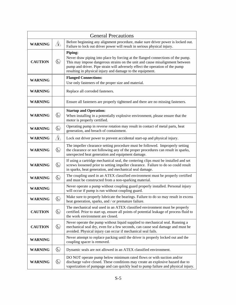
WARNING Before beginning any alignment procedure, make sure driver power is locked out. Failure to lock out driver power will result in serious physical injury.
CAUTION
Piping: Never draw piping into place by forcing at the flanged connections of the pump. This may impose dangerous strains on the unit and cause misalignment between pump and driver. Pipe strain will adversely effect the operation of the pump resulting in physical injury and damage to the equipment.
WARNING Flanged Connections: Use only fasteners of the proper size and material.
WARNING Replace all corroded fasteners.
WARNING Ensure all fasteners are properly tightened and there are no missing fasteners.
WARNING Startup and Operation: When installing in a potentially explosive environment, please ensure that the motor is properly certified.
WARNING Operating pump in reverse rotation may result in contact of metal parts, heat generation, and breach of containment.
WARNING Lock out driver power to prevent accidental start-up and physical injury.
WARNING The impeller clearance setting procedure must be followed. Improperly setting the clearance or not following any of the proper procedures can result in sparks, unexpected heat generation and equipment damage.
WARNING If using a cartridge mechanical seal, the centering clips must be installed and set screws loosened prior to setting impeller clearance. Failure to do so could result in sparks, heat generation, and mechanical seal damage.
WARNING The coupling used in an ATEX classified environment must be properly certified and must be constructed from a non-sparking material.
WARNING Never operate a pump without coupling guard properly installed. Personal injury will occur if pump is run without coupling guard.
WARNING Make sure to properly lubricate the bearings. Failure to do so may result in excess heat generation, sparks, and / or premature failure.
CAUTION The mechanical seal used in an ATEX classified environment must be properly certified. Prior to start up, ensure all points of potential leakage of process fluid to the work environment are closed.
CAUTION Never operate the pump without liquid supplied to mechanical seal. Running a mechanical seal dry, even for a few seconds, can cause seal damage and must be avoided. Physical injury can occur if mechanical seal fails.
WARNING Never attempt to replace packing until the driver is properly locked out and the coupling spacer is removed.
WARNING Dynamic seals are not allowed in an ATEX classified environment.
WARNING DO NOT operate pump below minimum rated flows or with suction and/or discharge valve closed. These conditions may create an explosive hazard due to vaporization of pumpage and can quickly lead to pump failure and physical injury.
S-6
General Precautions
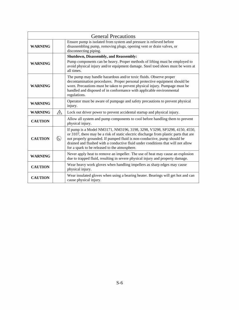
WARNING Ensure pump is isolated from system and pressure is relieved before disassembling pump, removing plugs, opening vent or drain valves, or disconnecting piping.
WARNING
Shutdown, Disassembly, and Reassembly: Pump components can be heavy. Proper methods of lifting must be employed to avoid physical injury and/or equipment damage. Steel toed shoes must be worn at all times.
WARNING
The pump may handle hazardous and/or toxic fluids. Observe proper decontamination procedures. Proper personal protective equipment should be worn. Precautions must be taken to prevent physical injury. Pumpage must be handled and disposed of in conformance with applicable environmental regulations.
WARNING Operator must be aware of pumpage and safety precautions to prevent physical injury.
WARNING Lock out driver power to prevent accidental startup and physical injury.
CAUTION Allow all system and pump components to cool before handling them to prevent physical injury.
CAUTION
If pump is a Model NM3171, NM3196, 3198, 3298, V3298, SP3298, 4150, 4550, or 3107, there may be a risk of static electric discharge from plastic parts that are not properly grounded. If pumped fluid is non-conductive, pump should be drained and flushed with a conductive fluid under conditions that will not allow for a spark to be released to the atmosphere.
WARNING Never apply heat to remove an impeller. The use of heat may cause an explosion due to trapped fluid, resulting in severe physical injury and property damage.
CAUTION Wear heavy work gloves when handling impellers as sharp edges may cause physical injury.
CAUTION Wear insulated gloves when using a bearing heater. Bearings will get hot and can cause physical injury.
S-7
ATEX CONSIDERATIONS and INTENDED USE Special care must be taken in potentially explosive environments to ensure that the equipment is properly maintained. This includes but is not limited to:
1. Monitoring the pump frame and liquid end temperature. 2. Maintaining proper bearing lubrication. 3. Ensuring that the pump is operated in the intended hydraulic range.
The ATEX conformance is only applicable when the pump unit is operated within its intended use. Operating, installing or maintaining the pump unit in any way that is not covered in the Instruction, Operation, and Maintenance manual (IOM) can cause serious personal injury or damage to the equipment. This includes any modification to the equipment or use of parts not provided by ITT Goulds Pumps. If there is any question regarding the intended use of the equipment, please contact an ITT Goulds representative before proceeding. Current IOMs are available at www.gouldspumps.com/literature_ioms.html or from your local ITT Goulds Pumps Sales representative.
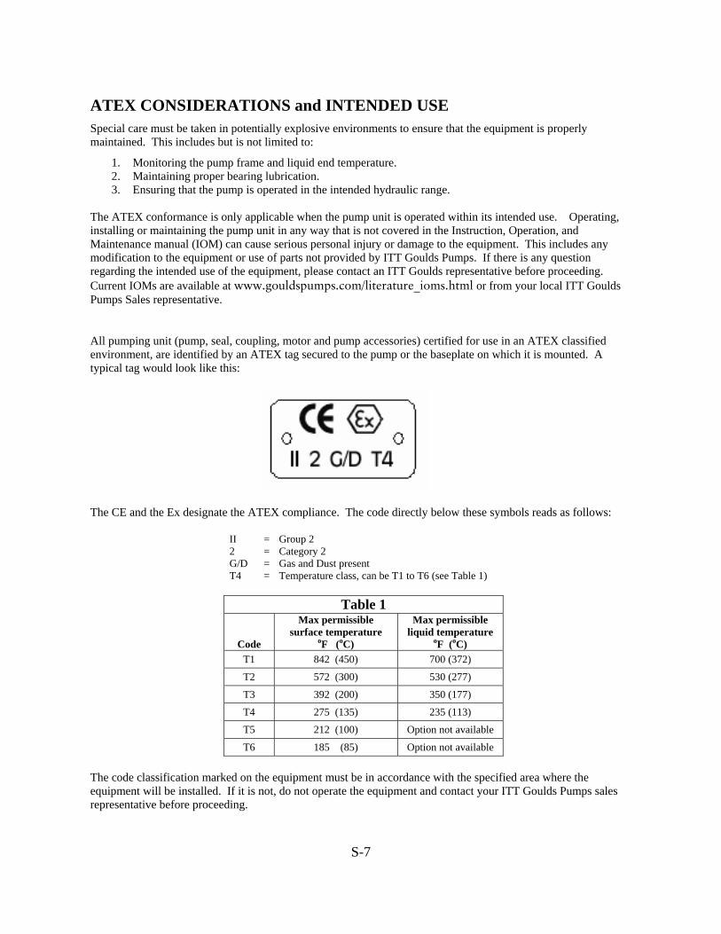
All pumping unit (pump, seal, coupling, motor and pump accessories) certified for use in an ATEX classified environment, are identified by an ATEX tag secured to the pump or the baseplate on which it is mounted. A typical tag would look like this:
The CE and the Ex designate the ATEX compliance. The code directly below these symbols reads as follows:
II = Group 2 2 = Category 2 G/D = Gas and Dust present T4 = Temperature class, can be T1 to T6 (see Table 1)
Table 1
Code
Max permissible surface temperature
oF (oC)
Max permissible liquid temperature
oF (oC) T1 842 (450) 700 (372)
T2 572 (300) 530 (277)
T3 392 (200) 350 (177)
T4 275 (135) 235 (113)
T5 212 (100) Option not available
T6 185 (85) Option not available
The code classification marked on the equipment must be in accordance with the specified area where the equipment will be installed. If it is not, do not operate the equipment and contact your ITT Goulds Pumps sales representative before proceeding.
S-8
PARTS
The use of genuine Goulds parts will provide the safest and most reliable operation of your pump. ITT Goulds Pumps ISO certification and quality control procedures ensure the parts are manufactured to the highest quality and safety levels. Please contact your local Goulds representative for details on genuine Goulds parts.
GENERAL INFORMATION
PUMP DESCRIPTION . . . . . . . . . . . . . . . . . . . . . . . . . . . 11
NAMEPLATE INFORMATION . . . . . . . . . . . . . . . . . . . . . 12
RECEIVING THE PUMP . . . . . . . . . . . . . . . . . . . . . . . . . 13
Storage Requirements . . . . . . . . . . . . . . . . . . . . . . . . . . 13
Handling . . . . . . . . . . . . . . . . . . . . . . . . . . . . . . . . . 13
PUMP DESCRIPTION
The Model 3298 is a sealless close coupled or framemounted centrifugal pump with an enclosed impeller that isdriven by a synchronous magnetic coupling and meetsdimensional standards of ANSI B73.1. (The 1x11
2-5 is notANSI dimensional.)
The SP 3298 is a self-priming sealless close coupled orframe mounted centrifugal pump with an enclosed impellerthat is driven by a synchronous magnetic coupling. Thepump and frame / adapter feet locations meet ANSI B73.1dimensional standards.
The V 3298 is a vertical in-line sealless close coupledcentrifugal pump with an enclosed impeller that is drivenby a synchronous magnetic coupling and meets thedimensional standards of ANSI B73.2.
Casing - The casings are one piece cast ductile iron linedwith 1/8" TEFZEL®1 and have ANSI class 150 flanges witha TEFZEL® raised face. The 3298 and SP 3298 are endsuction, top centerline discharge and are self-venting. TheV 3298 is side suction, side discharge and is alsoself-venting.
Impeller Magnet Assembly - The 3298 family utilizes aone or two piece impeller magnet assembly. The magnetring is balanced to ISO 1940 G6.3 levels and is sealedwithin the solid enclosed TEFZEL® impeller magnetassembly.
Stationary Shaft - The impeller magnet assembly rotatesabout a solid stationary silicon carbide shaft. The shaft issupported at one end by the containment shell and the otherend by the TEFZEL® bearing spider.
Bearing Spider - The bearing spider constructed fromsolid TEFZEL® houses one of the key silicon carbide thrustbearings in the pump and supports the stationary shaft atone end.
Rear Impeller Wear Ring - is standard on M and L groupsize pumps and is not required on S group sizes. The wearring is pressed into the rear of the impeller assembly. Thewear ring reduces axial thrust in the M and L group sizepumps.
Magnetic Coupling - is a coaxial synchronous type usingrare earth magnets. This concept results in a compactdesign and allows the impeller to turn at the same speed asthe motor, (i.e. there is no slip between the drive and drivenmagnets.)
Magnets - Neodymium Iron (NdFe).
Containment Shell - isolates the pumped liquid from theatmosphere. The containment shell construction is backedwith vinylester FRP.
Radial Bearings and Thrust Bearings - Goulds standardbearing material is carbon with optional Pure SinteredAlpha Grade Silicon Carbide or DryGuard™ Pure SinteredAlpha Grade Silicon Carbide.
Standard Close Coupled Mounting - The drive magnetassembly is keyed, set screwed and mounted directly to themotor shaft. This arrangement eliminates the need toperform pump/motor alignment.
Optional Power End3
- The standard configuration is castiron with flood oil lubricated ball bearings. Pure oil mistsystems are available as an option. For protection andreliability of the bearings and the lubricant, a labyrinth sealis provided. On the inboard side a lip seal is used to preventleakage of oil into the magnetic drive assembly.
3298 Family Rev. 5/08 11
2
1 TEFLON® and TEFZEL®: Registered trademarks for fluoropolymer resins, films and fibers made by DuPont.2 The 1x1 1
2-5 is tangential discharge.3 Frame mounted power end not available on the V 3298.
NAMEPLATE INFORMATION
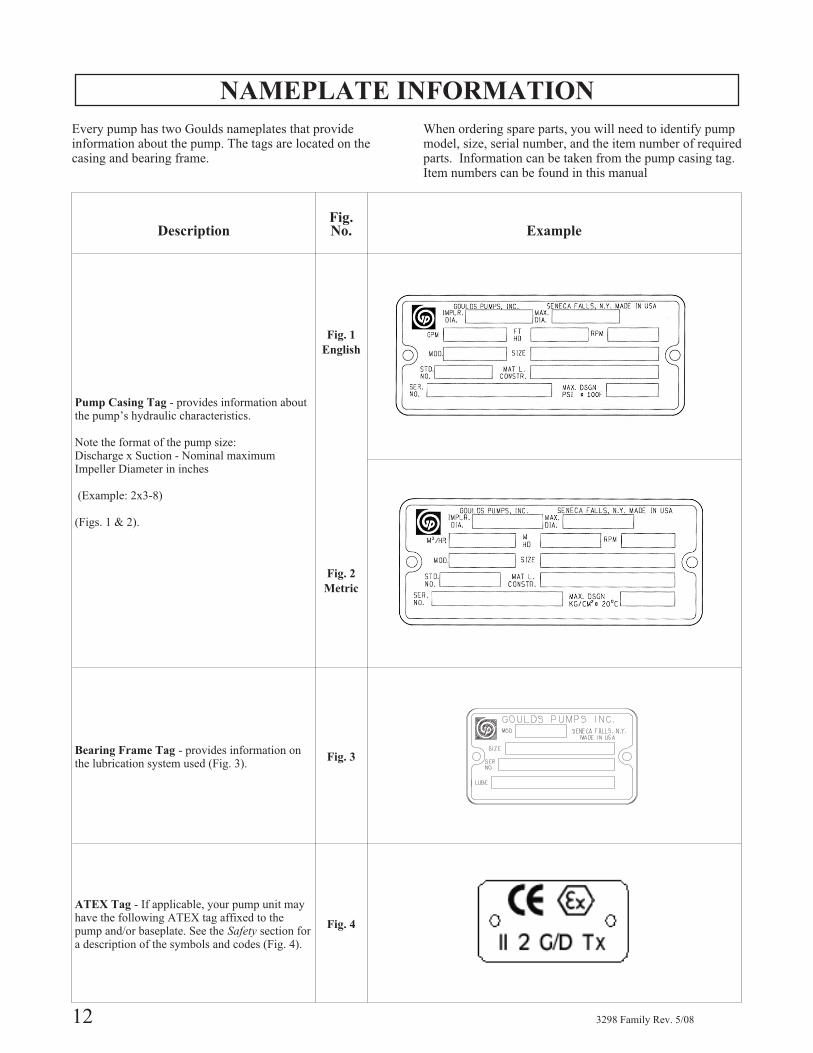
Every pump has two Goulds nameplates that provideinformation about the pump. The tags are located on thecasing and bearing frame.
When ordering spare parts, you will need to identify pumpmodel, size, serial number, and the item number of requiredparts. Information can be taken from the pump casing tag.Item numbers can be found in this manual
12 3298 Family Rev. 5/08
DescriptionFig.No. Example
Pump Casing Tag - provides information aboutthe pump’s hydraulic characteristics.
Note the format of the pump size:Discharge x Suction - Nominal maximumImpeller Diameter in inches
(Example: 2x3-8)
(Figs. 1 & 2).
Fig. 1
English
Fig. 2
Metric
Bearing Frame Tag - provides information onthe lubrication system used (Fig. 3).
Fig. 3
ATEX Tag - If applicable, your pump unit mayhave the following ATEX tag affixed to thepump and/or baseplate. See the Safety section fora description of the symbols and codes (Fig. 4).
Fig. 4

RECEIVING THE PUMP
Inspect the pump as soon as it is received. Make notes ofdamaged or missing items on the receipt and freight bill.File any claims with the transportation companyimmediately.
STORAGE REQUIREMENTSShort Term - (Less than 3 months) Goulds normalpackaging procedure is designed to protect the pumpduring shipping. Upon receipt store in a covered and drylocation.
Long Term - (More than 6 months) Preservative treatmentof bearings and machined surfaces will be required. Rotateshaft several times every 3 months. Refer to driver andcoupling manuals for their long term storage procedures.Store in a dry covered location.
HANDLING
▲! WARNINGFailure to properly lift and support equipment couldresult in serious injury or damage to pumps.
Use care when moving pumps. Lifting equipment must beable to adequately support the entire assembly. Hoist barepumps, using a sling under the suction flange and bearinghousing. (Fig. 5)
▲! WARNINGThese pumps use ceramic silicon carbide components.Do not drop pump or subject to shock loads, this maydamage internal ceramic components.
Baseplate mounted units are moved with slings under thepump and driver. (Figs. 5 & 7)
3298 Family Rev. 5/08 13
2
Fig. 5
Fig. 6
Fig. 7
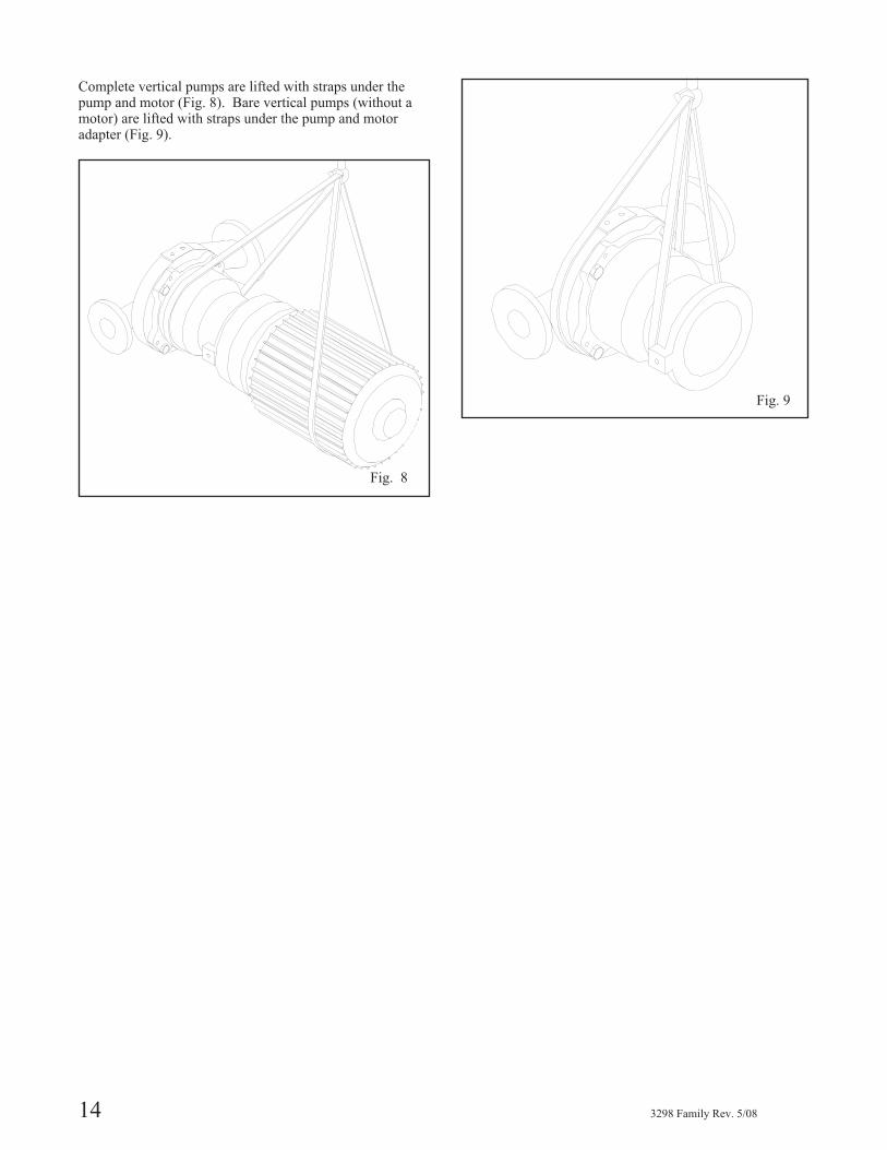
Complete vertical pumps are lifted with straps under thepump and motor (Fig. 8). Bare vertical pumps (without amotor) are lifted with straps under the pump and motoradapter (Fig. 9).
14 3298 Family Rev. 5/08
Fig. 8
Fig. 9
INSTALLATION
BASEPLATE INSPECTION. . . . . . . . . . . . . . . . . . . . . . . . 15
SITE/FOUNDATION. . . . . . . . . . . . . . . . . . . . . . . . . . . . 15
LEVEL BASEPLATE . . . . . . . . . . . . . . . . . . . . . . . . . . . 16
Cast Iron/Fabricated Steel . . . . . . . . . . . . . . . . . . . . . . . . 16
Feature Fabricated Steel/API Style. . . . . . . . . . . . . . . . . . . . 17
Baseplate Leveling Worksheet . . . . . . . . . . . . . . . . . . . . . . 18
ALIGNMENT AND ALIGNMENT PROCEDURE . . . . . . . . . . . 19
Alignment Checks . . . . . . . . . . . . . . . . . . . . . . . . . . . . 19
Alignment Criteria . . . . . . . . . . . . . . . . . . . . . . . . . . . . 19
Set Up. . . . . . . . . . . . . . . . . . . . . . . . . . . . . . . . . . . 20
Measurement . . . . . . . . . . . . . . . . . . . . . . . . . . . . . . . 20
Angular Alignment . . . . . . . . . . . . . . . . . . . . . . . . . . . . 20
Parallel Alignment . . . . . . . . . . . . . . . . . . . . . . . . . . . . 21
Complete Alignment . . . . . . . . . . . . . . . . . . . . . . . . . . . 21
Alignment Troubleshooting . . . . . . . . . . . . . . . . . . . . . . . 22
GROUT BASEPLATE . . . . . . . . . . . . . . . . . . . . . . . . . . . 22
PIPING. . . . . . . . . . . . . . . . . . . . . . . . . . . . . . . . . . . . 23
General . . . . . . . . . . . . . . . . . . . . . . . . . . . . . . . . . . 23
Suction Piping . . . . . . . . . . . . . . . . . . . . . . . . . . . . . . 23
Discharge Piping . . . . . . . . . . . . . . . . . . . . . . . . . . . . . 25
Final Piping Check . . . . . . . . . . . . . . . . . . . . . . . . . . . . 25
� Equipment that is to be installed in a potentially explosive environment must be done so in accordance with thefollowing installation instructions.
BASEPLATE INSPECTION
1. Remove all equipment.
2. Completely clean the underside of baseplate. It is
sometimes necessary to coat the underside of the
baseplate with an epoxy. This may have been
purchased as an option.
3. Remove the rust preventative solution from the
machined pads with an appropriate solution.
SITE / FOUNDATION
A pump should be located near the supply of liquid andhave adequate space for operation, maintenance, andinspection.
Baseplate mounted pumps are normally grouted to aconcrete foundation, which has been poured on a solidfooting. The foundation must be able to
absorb any vibration and to form a permanent, rigidsupport for the pumping unit.
The location and size of the foundation bolts are shown onthe outline assembly drawing, provided with the pump datapackage.
3298 Family Rev. 5/08 15
3
� All equipment being installed must be properlygrounded to prevent unexpected static electricdischarge. This includes ensuring that the PFAlined pumps are pumping fluids that are conductive.If not, a static electric discharge may occur when thepump is drained and disassembled for maintenancepurposes.
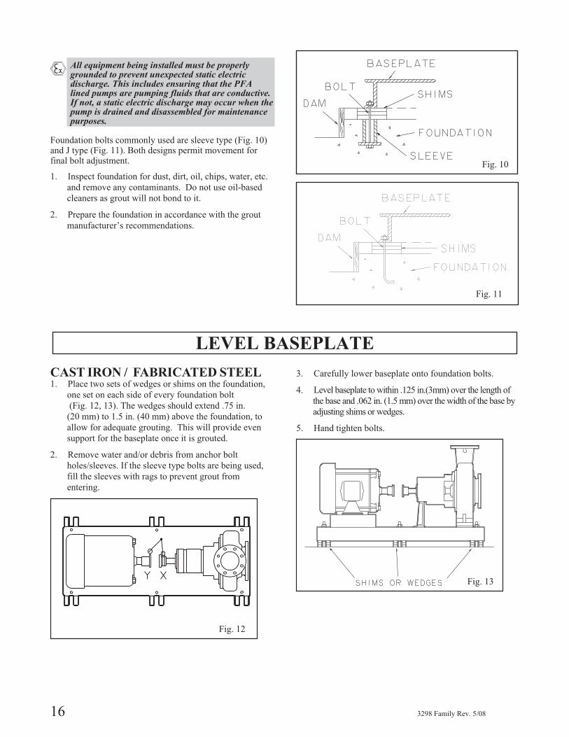
Foundation bolts commonly used are sleeve type (Fig. 10)and J type (Fig. 11). Both designs permit movement forfinal bolt adjustment.
1. Inspect foundation for dust, dirt, oil, chips, water, etc.
and remove any contaminants. Do not use oil-based
cleaners as grout will not bond to it.
2. Prepare the foundation in accordance with the grout
manufacturer’s recommendations.
LEVEL BASEPLATE
CAST IRON / FABRICATED STEEL1. Place two sets of wedges or shims on the foundation,
one set on each side of every foundation bolt
(Fig. 12, 13). The wedges should extend .75 in.
(20 mm) to 1.5 in. (40 mm) above the foundation, to
allow for adequate grouting. This will provide even
support for the baseplate once it is grouted.
2. Remove water and/or debris from anchor bolt
holes/sleeves. If the sleeve type bolts are being used,
fill the sleeves with rags to prevent grout from
entering.
3. Carefully lower baseplate onto foundation bolts.
4. Level baseplate to within .125 in.(3mm) over the length of
the base and .062 in. (1.5 mm) over the width of the base by
adjusting shims or wedges.
5. Hand tighten bolts.
16 3298 Family Rev. 5/08
Fig. 10
Fig. 11
Fig. 12
Fig. 13
FEATURE FABRICATED STEEL/API STYLE
(BASEPLATES PROVIDED WITH VERTICALLEVELING ADJUSTORS)
1. Coat the jack screws with an anti-seizing compound to
allow for easy removal after the grout has been cured.
2. Cut round circular plates from bar stock to set the jack
screws on. The edges of the plates should be
chamfered to reduce stress concentrations.
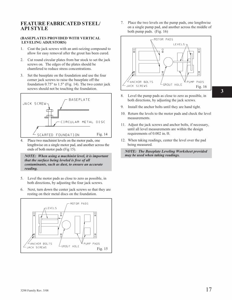
3. Set the baseplate on the foundation and use the four
corner jack screws to raise the baseplate off the
foundation 0.75" to 1.5" (Fig. 14). The two center jack
screws should not be touching the foundation.
4. Place two machinist levels on the motor pads, one
lengthwise on a single motor pad, and another across the
ends of both motor pads (Fig 15).
NOTE: When using a machinist level, it is importantthat the surface being leveled is free of allcontaminants, such as dust, to ensure an accuratereading.
5. Level the motor pads as close to zero as possible, in
both directions, by adjusting the four jack screws.
6. Next, turn down the center jack screws so that they are
resting on their metal discs on the foundation.
7. Place the two levels on the pump pads, one lengthwise
on a single pump pad, and another across the middle of
both pump pads. (Fig. 16)
8. Level the pump pads as close to zero as possible, in
both directions, by adjusting the jack screws.
9. Install the anchor bolts until they are hand tight.
10. Return the levels to the motor pads and check the level
measurements.
11. Adjust the jack screws and anchor bolts, if necessary,
until all level measurements are within the design
requirements of 0.002 in./ft.
12. When taking readings, center the level over the pad
being measured.
NOTE: The Baseplate Leveling Worksheet providedmay be used when taking readings.
3298 Family Rev. 5/08 17
3
Fig. 14
Fig. 15
Fig. 16
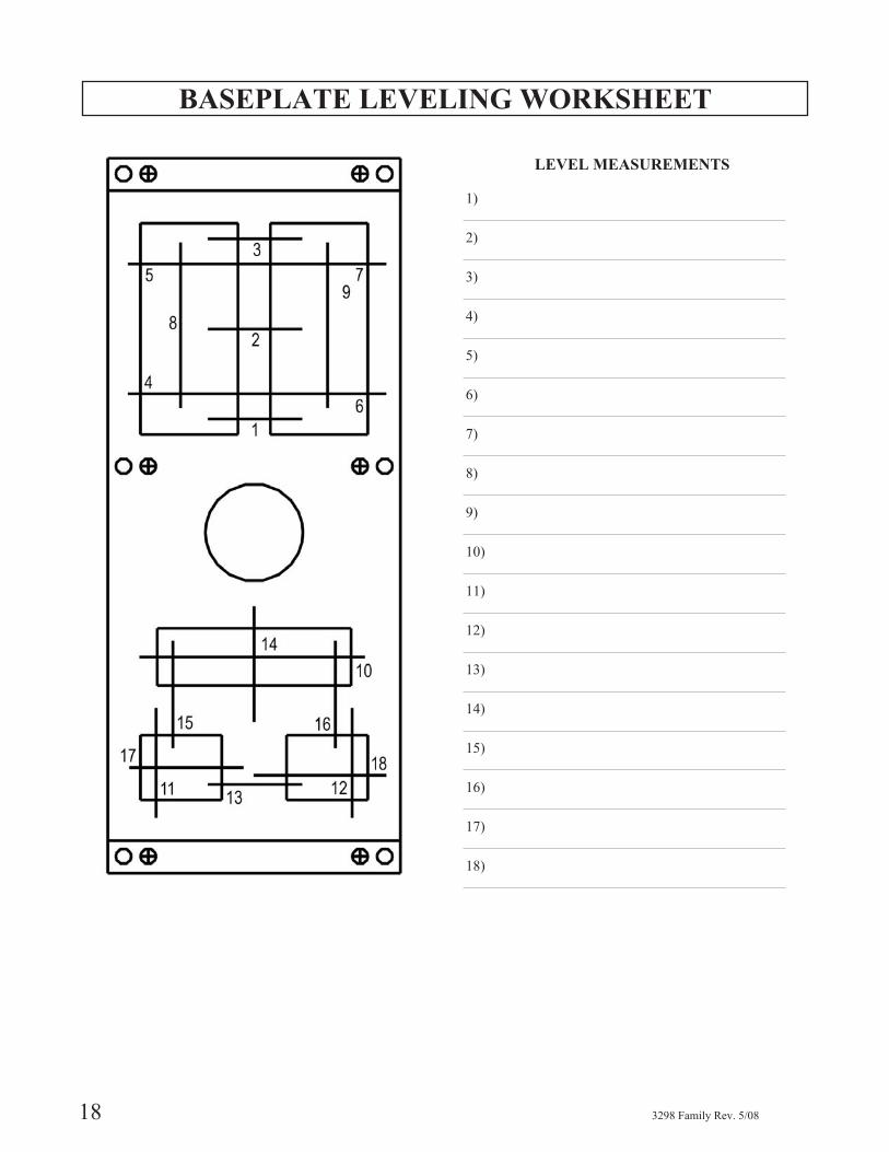
BASEPLATE LEVELING WORKSHEET
LEVEL MEASUREMENTS
1)
2)
3)
4)
5)
6)
7)
8)
9)
10)
11)
12)
13)
14)
15)
16)
17)
18)
18 3298 Family Rev. 5/08

ALIGNMENT AND ALIGNMENT PROCEDURE
▲! WARNINGBefore beginning any alignment procedure, make suredriver power is locked out. Failure to lock out driverpower can result in serious personal injury.
� Alignment procedures must be followed to preventunintended contact of rotating parts. Followcoupling manufacturer's coupling installation andoperation procedures.
To remove guard, refer to coupling guard assembly/disassembly instructions.
The points at which alignment is checked and adjusted are:
� Initial Alignment is done prior to operation when
the pump and the driver are at ambient temperature.
� Final Alignment is done after operation when the
pump and driver are at operating temperature.
Alignment is achieved by adding or removing shims fromunder the feet of the driver and shifting equipmenthorizontally as needed.
NOTE: Proper alignment is the responsibility of theinstaller of the unit.
Accurate alignment of the equipment must be attained.Trouble-free operation can be accomplished by followingthese procedures:
ALIGNMENT CHECKS
Initial Alignment (Cold Alignment)
� Before Grouting Baseplate - To ensure alignment can be
obtained.
� After Grouting Baseplate - To ensure no changes to
alignment have occurred during grouting process.
� After Connecting Piping - To ensure that pipe strains
haven’t altered alignment. If changes have occurred,
alter piping to remove pipe strains on pump flanges.
Final Alignment (Hot Alignment)
� After First Run - To obtain correct alignment when both
pump and driver are at operating temperature.
Thereafter, alignment should be checked periodically in
accordance with plant operating and maintenance
procedures.
NOTE: Alignment check must be made if processtemperature changes, piping changes, and/or pumpservice is performed.
ALIGNMENT CRITERIAGood alignment is achieved when the dial indicatorreadings as specified in the alignment procedure are .002in. (.05 mm) Total Indicated Reading (T.I.R.) or less whenthe pump and driver are at operating temperature (FinalAlignment).
During the installation phase, however, it is necessary toset the parallel alignment in the vertical direction to adifferent criteria due to differences in expansion rates ofthe pump and driver. Table 2 below shows recommendedcold settings for electric motor driven pumps based ondifferent pumpage temperatures. Driver manufacturersshould be consulted for recommended cold settings forother types of drivers (steam turbines, engines, etc.).
Table 2Cold Settings of Parallel
Vertical Alignment
PumpageTemperature Set Driver Shaft
50°F (10°C) .002in. (.05mm) LOW
150°F (65°C) .001in. (.03mm) HIGH
250°F (120°C) .005in. (.12mm) HIGH
3298 Family Rev. 5/08 19
3
B
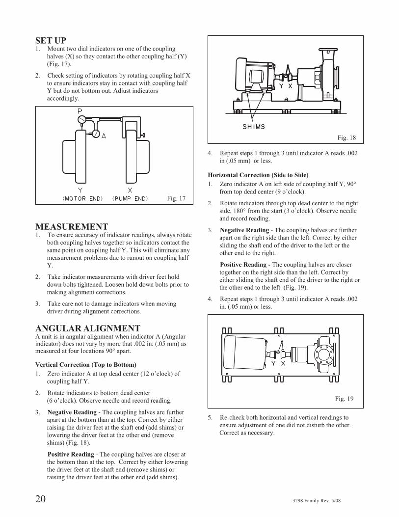
SET UP1. Mount two dial indicators on one of the coupling
halves (X) so they contact the other coupling half (Y)
(Fig. 17).
2. Check setting of indicators by rotating coupling half X
to ensure indicators stay in contact with coupling half
Y but do not bottom out. Adjust indicators
accordingly.
MEASUREMENT1. To ensure accuracy of indicator readings, always rotate
both coupling halves together so indicators contact the
same point on coupling half Y. This will eliminate any
measurement problems due to runout on coupling half
Y.
2. Take indicator measurements with driver feet hold
down bolts tightened. Loosen hold down bolts prior to
making alignment corrections.
3. Take care not to damage indicators when moving
driver during alignment corrections.
ANGULAR ALIGNMENTA unit is in angular alignment when indicator A (Angularindicator) does not vary by more that .002 in. (.05 mm) asmeasured at four locations 90° apart.
Vertical Correction (Top to Bottom)
1. Zero indicator A at top dead center (12 o’clock) of
coupling half Y.
2. Rotate indicators to bottom dead center
(6 o’clock). Observe needle and record reading.
3. Negative Reading - The coupling halves are further
apart at the bottom than at the top. Correct by either
raising the driver feet at the shaft end (add shims) or
lowering the driver feet at the other end (remove
shims) (Fig. 18).
Positive Reading - The coupling halves are closer at
the bottom than at the top. Correct by either lowering
the driver feet at the shaft end (remove shims) or
raising the driver feet at the other end (add shims).
4. Repeat steps 1 through 3 until indicator A reads .002
in (.05 mm) or less.
Horizontal Correction (Side to Side)
1. Zero indicator A on left side of coupling half Y, 90°
from top dead center (9 o’clock).
2. Rotate indicators through top dead center to the right
side, 180° from the start (3 o’clock). Observe needle
and record reading.
3. Negative Reading - The coupling halves are further
apart on the right side than the left. Correct by either
sliding the shaft end of the driver to the left or the
other end to the right.
Positive Reading - The coupling halves are closer
together on the right side than the left. Correct by
either sliding the shaft end of the driver to the right or
the other end to the left (Fig. 19).
4. Repeat steps 1 through 3 until indicator A reads .002
in. (.05 mm) or less.
5. Re-check both horizontal and vertical readings to
ensure adjustment of one did not disturb the other.
Correct as necessary.
20 3298 Family Rev. 5/08
Fig. 17
Fig. 18
Fig. 19
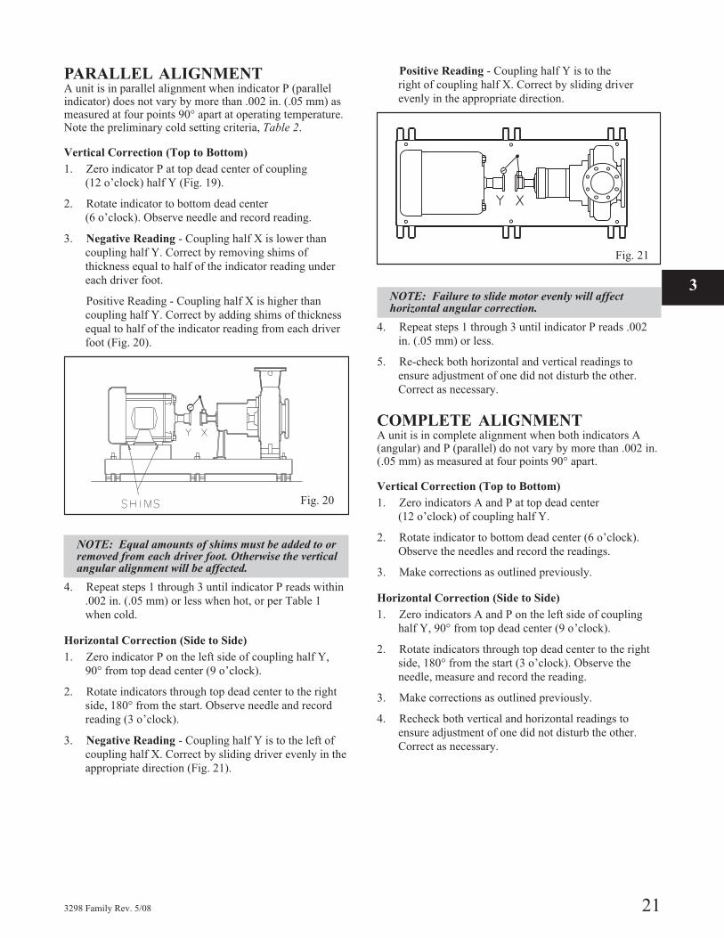
PARALLEL ALIGNMENTA unit is in parallel alignment when indicator P (parallelindicator) does not vary by more than .002 in. (.05 mm) asmeasured at four points 90° apart at operating temperature.Note the preliminary cold setting criteria, Table 2.
Vertical Correction (Top to Bottom)
1. Zero indicator P at top dead center of coupling
(12 o’clock) half Y (Fig. 19).
2. Rotate indicator to bottom dead center
(6 o’clock). Observe needle and record reading.
3. Negative Reading - Coupling half X is lower than
coupling half Y. Correct by removing shims of
thickness equal to half of the indicator reading under
each driver foot.
Positive Reading - Coupling half X is higher than
coupling half Y. Correct by adding shims of thickness
equal to half of the indicator reading from each driver
foot (Fig. 20).
NOTE: Equal amounts of shims must be added to orremoved from each driver foot. Otherwise the verticalangular alignment will be affected.
4. Repeat steps 1 through 3 until indicator P reads within
.002 in. (.05 mm) or less when hot, or per Table 1
when cold.
Horizontal Correction (Side to Side)
1. Zero indicator P on the left side of coupling half Y,
90° from top dead center (9 o’clock).
2. Rotate indicators through top dead center to the right
side, 180° from the start. Observe needle and record
reading (3 o’clock).
3. Negative Reading - Coupling half Y is to the left of
coupling half X. Correct by sliding driver evenly in the
appropriate direction (Fig. 21).
Positive Reading - Coupling half Y is to the
right of coupling half X. Correct by sliding driver
evenly in the appropriate direction.
NOTE: Failure to slide motor evenly will affecthorizontal angular correction.
4. Repeat steps 1 through 3 until indicator P reads .002
in. (.05 mm) or less.
5. Re-check both horizontal and vertical readings to
ensure adjustment of one did not disturb the other.
Correct as necessary.
COMPLETE ALIGNMENTA unit is in complete alignment when both indicators A(angular) and P (parallel) do not vary by more than .002 in.(.05 mm) as measured at four points 90° apart.
Vertical Correction (Top to Bottom)
1. Zero indicators A and P at top dead center
(12 o’clock) of coupling half Y.
2. Rotate indicator to bottom dead center (6 o’clock).
Observe the needles and record the readings.
3. Make corrections as outlined previously.
Horizontal Correction (Side to Side)
1. Zero indicators A and P on the left side of coupling
half Y, 90° from top dead center (9 o’clock).
2. Rotate indicators through top dead center to the right
side, 180° from the start (3 o’clock). Observe the
needle, measure and record the reading.
3. Make corrections as outlined previously.
4. Recheck both vertical and horizontal readings to
ensure adjustment of one did not disturb the other.
Correct as necessary.
3298 Family Rev. 5/08 21
3
Fig. 21
Fig. 20
ALIGNMENT TROUBLESHOOTING
NOTE: With experience, the installer will understandthe interaction between angular and parallel and willmake corrections appropriately.
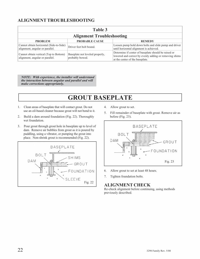
GROUT BASEPLATE
1. Clean areas of baseplate that will contact grout. Do not
use an oil-based cleaner because grout will not bond to it.
2. Build a dam around foundation (Fig. 22). Thoroughly
wet foundation.
3. Pour grout through grout hole in baseplate up to level of
dam. Remove air bubbles from grout as it is poured by
puddling, using a vibrator, or pumping the grout into
place. Non-shrink grout is recommended (Fig. 22).
4. Allow grout to set.
5. Fill remainder of baseplate with grout. Remove air as
before (Fig. 23).
6. Allow grout to set at least 48 hours.
7. Tighten foundation bolts.
ALIGNMENT CHECKRe-check alignment before continuing, using methodspreviously described.
22 3298 Family Rev. 5/08
Table 3
Alignment TroubleshootingPROBLEM PROBABLE CAUSE REMEDY
Cannot obtain horizontal (Side-to-Side)
alignment, angular or parallel.Driver feet bolt bound.
Loosen pump hold down bolts and slide pump and driver
until horizontal alignment is achieved.
Cannot obtain vertical (Top to Bottom)
alignment, angular or parallel.
Baseplate not leveled properly,
probably bowed.
Determine if center of baseplate should be raised or
lowered and correct by evenly adding or removing shims
at the center of the baseplate.
Fig. 22
Fig. 23
PIPING
Guidelines for piping are given in the Centrifugal Pumpsection of the “Hydraulic Institute Standards” and shouldbe reviewed prior to pump installation.
▲! WARNINGNever draw piping into place by forcing at the flangedconnections of the pump. This will impose dangerousstrains on the unit and cause misalignment betweenpump and driver. Pipe strain can adversely effect theoperation of the pump. That could result in seriouspersonal injury and damage to equipment.
� Flange loads from the piping system, includingthose from thermal expansion of the piping, mustnot exceed the limits of the pump. Casing deforma-tion can result in contact with rotating parts andresult in excess heat generation, sparks andpremature failure.
1. All piping must be supported independently and must
line up naturally with the pump flanges.
2. Piping runs shall be designed to minimize friction
losses.
3. DO NOT make final connection of piping to pump
until grout has hardened and pump and driver
hold-down bolts have been tightened.
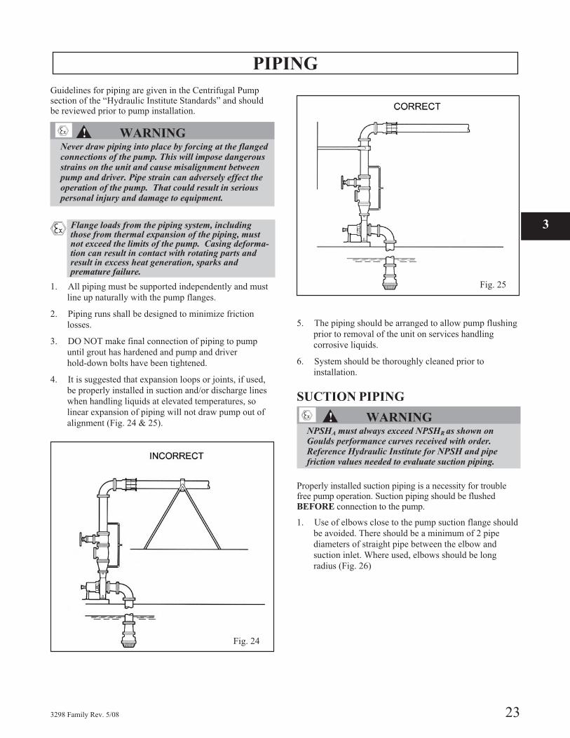
4. It is suggested that expansion loops or joints, if used,
be properly installed in suction and/or discharge lines
when handling liquids at elevated temperatures, so
linear expansion of piping will not draw pump out of
alignment (Fig. 24 & 25).
5. The piping should be arranged to allow pump flushing
prior to removal of the unit on services handling
corrosive liquids.
6. System should be thoroughly cleaned prior to
installation.
SUCTION PIPING
▲! WARNINGNPSHA must always exceed NPSHR as shown onGoulds performance curves received with order.Reference Hydraulic Institute for NPSH and pipefriction values needed to evaluate suction piping.
Properly installed suction piping is a necessity for troublefree pump operation. Suction piping should be flushedBEFORE connection to the pump.
1. Use of elbows close to the pump suction flange should
be avoided. There should be a minimum of 2 pipe
diameters of straight pipe between the elbow and
suction inlet. Where used, elbows should be long
radius (Fig. 26)
3298 Family Rev. 5/08 23
A
A
Fig. 24
Fig. 25
3
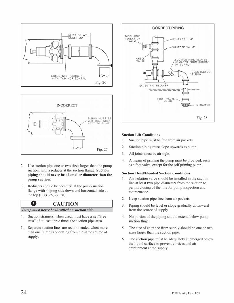
2. Use suction pipe one or two sizes larger than the pump
suction, with a reducer at the suction flange. Suction
piping should never be of smaller diameter than the
pump suction.
3. Reducers should be eccentric at the pump suction
flange with sloping side down and horizontal side at
the top (Figs. 26, 27, 28).
� CAUTIONPump must never be throttled on suction side.
4. Suction strainers, when used, must have a net “free
area” of at least three times the suction pipe area.
5. Separate suction lines are recommended when more
than one pump is operating from the same source of
supply.
Suction Lift Conditions
1. Suction pipe must be free from air pockets
2. Suction piping must slope upwards to pump.
3. All joints must be air tight.
4. A means of priming the pump must be provided, such
as a foot valve, except for the self priming pump.
Suction Head/Flooded Suction Conditions
1. An isolation valve should be installed in the suction
line at least two pipe diameters from the suction to
permit closing of the line for pump inspection and
maintenance.
2. Keep suction pipe free from air pockets.
3. Piping should be level or slope gradually downward
from the source of supply
4. No portion of the piping should extend below pump
suction flnge.
5. The size of entrance from supply should be one or two
sizes larger than the suction pipe.
6. The suction pipe must be adequately submerged below
the liquid surface to prevent vortices and air
entrainment at the supply.
24 3298 Family Rev. 5/08
CORRECT PIPING
Fig. 27
CORRECT
Fig. 26
Fig. 28
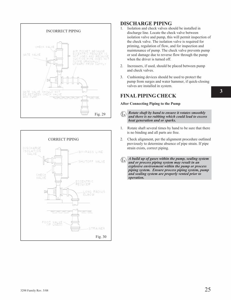
DISCHARGE PIPING1. Isolation and check valves should be installed in
discharge line. Locate the check valve between
isolation valve and pump, this will permit inspection of
the check valve. The isolation valve is required for
priming, regulation of flow, and for inspection and
maintenance of pump. The check valve prevents pump
or seal damage due to reverse flow through the pump
when the driver is turned off.
2. Increasers, if used, should be placed between pump
and check valves.
3. Cushioning devices should be used to protect the
pump from surges and water hammer, if quick-closing
valves are installed in system.
FINAL PIPING CHECK
After Connecting Piping to the Pump
� Rotate shaft by hand to ensure it rotates smoothlyand there is no rubbing which could lead to excessheat generation and or sparks.
1. Rotate shaft several times by hand to be sure that there
is no binding and all parts are free.
2. Check alignment, per the alignment procedure outlined
previously to determine absence of pipe strain. If pipe
strain exists, correct piping.
� A build up of gases within the pump, sealing systemand or process piping system may result in anexplosive environment within the pump or processpiping system. Ensure process piping system, pumpand sealing system are properly vented prior tooperation.
3298 Family Rev. 5/08 25
Fig. 29
INCORRECT PIPING
Fig. 30
CORRECT PIPING
3

26 3298 Family Rev. 5/08
OPERATION
PREPARATION FOR START-UP . . . . . . . . . . . . . . . . . . . . 27
Checking Rotation - Frame Mounted . . . . . . . . . . . . . . . . . . 27
Couple Pump and Driver . . . . . . . . . . . . . . . . . . . . . . . . . 27
Install Coupling Guard . . . . . . . . . . . . . . . . . . . . . . . . . . 27
Checking Rotation - Close Coupled . . . . . . . . . . . . . . . . . . . 28
Lubricating Bearings . . . . . . . . . . . . . . . . . . . . . . . . . . . 28
Connect Condition Monitoring Devices . . . . . . . . . . . . . . . . . 28
Priming Pump . . . . . . . . . . . . . . . . . . . . . . . . . . . . . . 28
STARTING PUMP . . . . . . . . . . . . . . . . . . . . . . . . . . . . . 28
OPERATION . . . . . . . . . . . . . . . . . . . . . . . . . . . . . . . . 29
General Considerations. . . . . . . . . . . . . . . . . . . . . . . . . . 29
Operating at Reduced Capacity . . . . . . . . . . . . . . . . . . . . . 29
Suction Valve Closed / Dry Run Operation . . . . . . . . . . . . . . . 29
Draining Tanks / Dry Run Operation . . . . . . . . . . . . . . . . . . 29
Discharge Valve Closed . . . . . . . . . . . . . . . . . . . . . . . . . 29
Operating Under Freezing Conditions . . . . . . . . . . . . . . . . . . 30
3298 MINIMUM CONTINUOUS RECOMMENDED FLOW . . . . . 30
SHUTDOWN . . . . . . . . . . . . . . . . . . . . . . . . . . . . . . . . 31
FINAL ALIGNMENT . . . . . . . . . . . . . . . . . . . . . . . . . . . 31
PREPARATION FOR START-UP
� When installing in a potentially explosive environ-ment, please ensure that the motor is properlycertified.
CHECKING ROTATION -FRAME MOUNTED
� CAUTION
Serious damage may result if pump is run in thewrong rotation.
1. Lock out power to driver.
▲! WARNINGLock out driver power to prevent accidental start-upthat could result in serious personal injury.
2. Make sure coupling spacer is removed and coupling
hubs are fastened tightly to the shafts and are not loose.
NOTE: Pump is shipped with coupling spacer removed.
3. Unlock driver power.
4. Make sure everyone is clear. Jog driver just long enough
to determine direction of rotation. Rotation must
correspond to arrow on bearing frame.
5. Lock out power to driver.
COUPLE PUMP AND DRIVER
▲! WARNINGLock out driver power to prevent accidental start-upthat could result in serious personal injury.
Lubricate coupling per manufacturer’s instructions andinstall coupling spacer.
INSTALL COUPLING GUARDInstall coupling guard as defined in the appendix.
▲! WARNINGNever operate a pump without a coupling guardproperly installed. Operating pump without a properlyinstalled coupling guard can result in serious personalinjury.
3298 Family Rev. 5/08 27
B
B
4
CHECKING ROTATION - CLOSECOUPLED
�! CAUTION
Serious damage may result if pump is runin the wrong rotation.
1. Unlock driver power.
2. Make sure everyone is clear. Jog driver just long
enough to determine direction of rotation. Rotation of
motor fan must correspond to arrow on close coupled
frame.
LUBRICATING BEARINGS
� Bearings must be lubricated properly in order toprevent excess heat generation, sparks, andpremature failure.
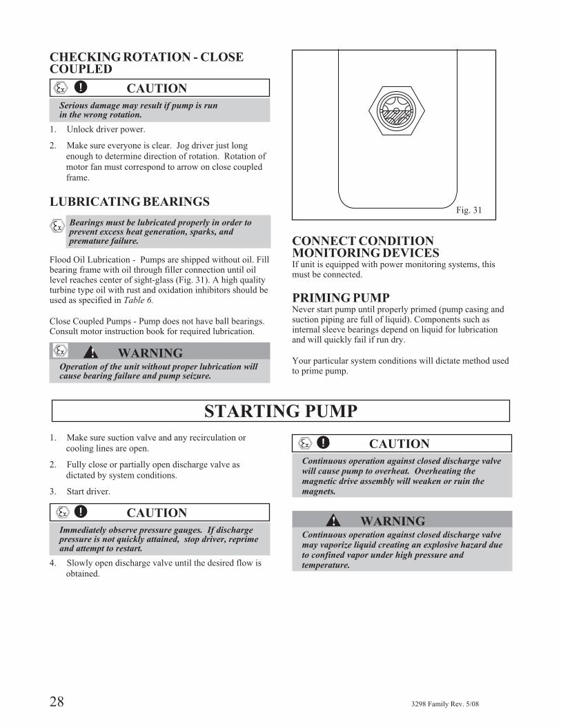
Flood Oil Lubrication - Pumps are shipped without oil. Fillbearing frame with oil through filler connection until oillevel reaches center of sight-glass (Fig. 31). A high qualityturbine type oil with rust and oxidation inhibitors should beused as specified in Table 6.
Close Coupled Pumps - Pump does not have ball bearings.Consult motor instruction book for required lubrication.
▲! WARNINGOperation of the unit without proper lubrication willcause bearing failure and pump seizure.
CONNECT CONDITIONMONITORING DEVICESIf unit is equipped with power monitoring systems, thismust be connected.
PRIMING PUMPNever start pump until properly primed (pump casing andsuction piping are full of liquid). Components such asinternal sleeve bearings depend on liquid for lubricationand will quickly fail if run dry.
Your particular system conditions will dictate method usedto prime pump.
STARTING PUMP
1. Make sure suction valve and any recirculation or
cooling lines are open.
2. Fully close or partially open discharge valve as
dictated by system conditions.
3. Start driver.
�! CAUTION
Immediately observe pressure gauges. If dischargepressure is not quickly attained, stop driver, reprimeand attempt to restart.
4. Slowly open discharge valve until the desired flow is
obtained.
�! CAUTION
Continuous operation against closed discharge valvewill cause pump to overheat. Overheating themagnetic drive assembly will weaken or ruin themagnets.
▲! WARNINGContinuous operation against closed discharge valvemay vaporize liquid creating an explosive hazard dueto confined vapor under high pressure andtemperature.
28 3298 Family Rev. 5/08
Fig. 31
OPERATION
GENERAL CONSIDERATIONSAlways vary capacity with valve in discharge line. NEVERthrottle flow from suction side.
Driver may overload or magnets de-couple if pumpagespecific gravity (density) is greater than originally assumed,or rated flow rate is exceeded.
Always operate the pump at or near the rated conditions toprevent damage resulting from cavitation or recirculation.
� CAUTION
Do not operate above rated temperature range ofmagnets as this will weaken or ruin the magnets.
� Service temperature in an ATEX classified environ-ment is limited by Table 1 in the Safety section.
Table 4Temperature Ratings
Group Size Rated Temperature
XS 1x1.5-5 250° F (121° C)
S All 250° F (121° C)
M All 250° F (121° C)
L All 250° F (121° C)
OPERATINGATREDUCED CAPACITY
▲! WARNINGDo NOT operate pump below minimum rated flows orwith discharge valve closed. These conditions mayvaporize liquid creating an explosive hazard due toconfined vapor under high pressure and temperature.
SUCTION VALVE CLOSED / DRYRUNOPERATION
▲! WARNINGDo not operate pump with suction valve closed.Operating pump after suction valve closed will causewear of thrust and radial bearings and pump failure.Operating pump with suction valve closed mayvaporize liquid creating an explosvie hazard due toconfined vapor under high pressure and temperature.
� CAUTION
Always vary capacity with regulating valve in thedischarge line. NEVER throttle flow from the suctionside.
� CAUTION
Driver may overload if the pumpage specific gravity(density) is greater than originally assumed, or therated flow rate is exceeded.
� CAUTION
Always operate the pump at or near the ratedconditions to prevent damage resulting from cavitationor recirculation.
� CAUTION
Damage occurs from:
1. Increased vibration levels - Affects bearings.2. Increased radial loads - Stresses on shaft and
bearings.3. Heat build up - Vaporization causing rotating parts
to score or seize.4. Cavitation - Damage to internal surfaces of pump.
Goulds recommends the use of a power monitor to preventpump damage from systems which have the potential fordry run operation. Refer to Appendix for information onpower monitors.
DRAINING TANKS / DRY RUNOPERATION
▲! WARNINGAfter pump has drained tank, it should be shut downimmediately. Operating pump after the tank has beendrained of liquid will cause wear of thrust and radialbearings and pump failure. Operating pump aftertank has been drained of liquid may vaporize liquidcreating an explosive hazard due to confined vaporunder high pressure and temperature.
Goulds recommends the use of a power monitor to preventpump damage from systems which have the potential fordry run operation.
DISCHARGE VALVE CLOSED
▲! WARNINGDo not operate pump with discharge valve closed.Operating pump with a closed discharge valve mayvaporize liquid creating an explosive hazard due toconfined vapor under high pressure and temperature.
Goulds recommends the use of a power monitor and/or aminimum flow by-pass line to prevent pump damage fromsystems which have the potential for closed discharge operation.
3298 Family Rev. 5/08 29
4
OPERATING UNDERFREEZING CONDITIONSExposure to freezing conditions, while pump is idle, couldcause liquid to freeze and damage the pump. Liquid insidepump should be drained. Liquid inside cooling coils, ifsupplied, should also be drained.
3298 Minimum Continuous Recommended Flow
30 3298 Family Rev. 5/08
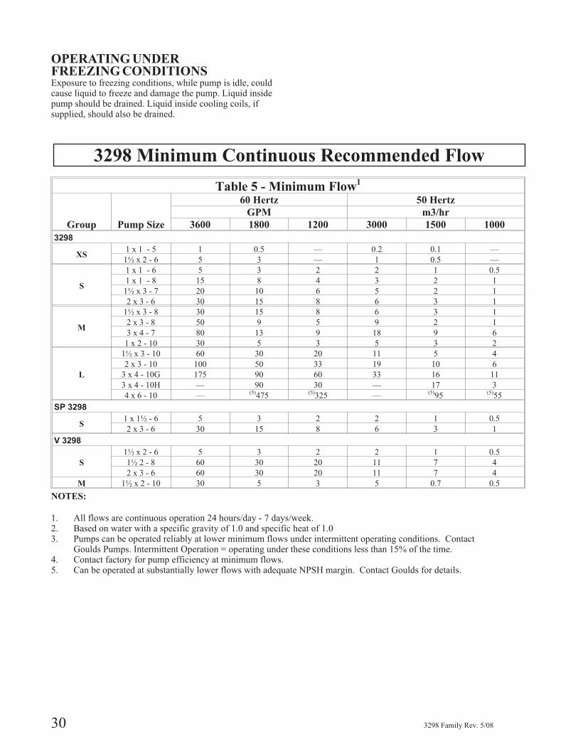
Table 5 - Minimum Flow1
Group Pump Size
60 Hertz 50 Hertz
GPM m3/hr
3600 1800 1200 3000 1500 1000
3298
XS1 x 1 - 5 1 0.5 — 0.2 0.1 —
1½ x 2 - 6 5 3 — 1 0.5 —
S
1 x 1 - 6 5 3 2 2 1 0.5
1 x 1 - 8 15 8 4 3 2 1
1½ x 3 - 7 20 10 6 5 2 1
2 x 3 - 6 30 15 8 6 3 1
M
1½ x 3 - 8 30 15 8 6 3 1
2 x 3 - 8 50 9 5 9 2 1
3 x 4 - 7 80 13 9 18 9 6
1 x 2 - 10 30 5 3 5 3 2
L
1½ x 3 - 10 60 30 20 11 5 4
2 x 3 - 10 100 50 33 19 10 6
3 x 4 - 10G 175 90 60 33 16 11
3 x 4 - 10H — 90 30 — 17 3
4 x 6 - 10 — (5)475 (5)325 — (5)95 (5)55
SP 3298
S1 x 1½ - 6 5 3 2 2 1 0.5
2 x 3 - 6 30 15 8 6 3 1
V 3298
S
1½ x 2 - 6 5 3 2 2 1 0.5
1½ 2 - 8 60 30 20 11 7 4
2 x 3 - 6 60 30 20 11 7 4
M 1½ x 2 - 10 30 5 3 5 0.7 0.5
NOTES:
1. All flows are continuous operation 24 hours/day - 7 days/week.2. Based on water with a specific gravity of 1.0 and specific heat of 1.03. Pumps can be operated reliably at lower minimum flows under intermittent operating conditions. Contact
Goulds Pumps. Intermittent Operation = operating under these conditions less than 15% of the time.4. Contact factory for pump efficiency at minimum flows.5. Can be operated at substantially lower flows with adequate NPSH margin. Contact Goulds for details.
SHUTDOWN
1. Slowly close discharge valve.
2. Shut down and lock out driver to prevent accidental
rotation.
▲! WARNINGWhen handling hazardous and/or toxic fluids, skin, eyeand respiratory protection are required. If pump isbeing drained, precautions must be taken to preventinjury or environmental contamination. Pumpagemust be handled and disposed of in conformance withapplicable environmental regulations.
FINAL ALIGNMENT
� Alignment procedures must be followed to preventunintended contact of rotating parts. Followcoupling manufacturer's coupling installation andoperation procedures.
1. Run the unit under actual operating conditions for a
sufficient length of time to bring the pump and driver
up to operating temperature.
2. Check and reset alignment per alignment procedure
outlined earlier.
3. Reinstall coupling guard per instruction in appendix.
3298 Family Rev. 5/08 31
4

32 3298 Family Rev. 5/08
PREVENTIVE MAINTENANCE
GENERAL COMMENTS . . . . . . . . . . . . . . . . . . . . . . . . . 33
MAINTENANCE SCHEDULE . . . . . . . . . . . . . . . . . . . . . . 33
MAINTENANCE OF BEARINGS — Frame Mounted . . . . . . . . . 34
TROUBLESHOOTING . . . . . . . . . . . . . . . . . . . . . . . . . . 35
GENERAL COMMENTS
A routine maintenance program can extend the life of your pump. Well maintained equip-
ment will last longer and require fewer repairs. It is recommended that maintenance re-
cords be kept to help pinpoint potential causes of problems.
� The preventive maintenance section must be adhered to in order to keep the applicable ATEX classification of theequipment. Failure to follow these procedures will void the ATEX classification for the equipment.
MAINTENANCE SCHEDULE
ROUTINE MAINTENANCE
� Bearing lubrication (frame mounted pumps)
� Vibration analysis
� Discharge pressure
ROUTINE INSPECTIONS
� Check level and condition of oil through sight glass
on bearing frame. (frame mounted Pumps)
� Check for unusual noise, vibration, and bearing tem-
peratures.
� Inspect pump and piping for leaks.
3 MONTH MAINTENANCE
� Check foundation hold down bolts of motor and
pump for tightness.
� Change oil per (frame mounted pumps) per guide-
lines on following page.
� Check alignment per section 3.
YEARLY INSPECTIONS
� Check pump capacity, pressure, and power. If the
pump performance does not satisfy your process re-
quirements, the pump should be disassembled and in-
spected. Worn parts should be replaced.
INSPECTION INTERVALSInspection intervals should be shortened appropriately ifthe pumpage is abrasive and/or corrosive,
� or if the environment is classified as potentiallyexplosive.
3298 Family Rev. 5/08 33
5
MAINTENANCE OF BEARINGS—FRAME MOUNTED
STANDARD CLOSE COUPLED PUMPMany 3298s, SP 3298s, and V 3298s are close coupledmounted as standard. Close coupled pumps do not havebearings which require lubrication.
� Throughout this section on bearing lubrication,different pumpage temperatures are listed. If theequipment is ATEX certified and the listedtemperature exceeds the applicable value shown inTable 1 under Safety, then that temperature is notvalid. When this situation occurs, please consultwith your ITT/Goulds representative.
OIL LUBRICATED BEARINGS
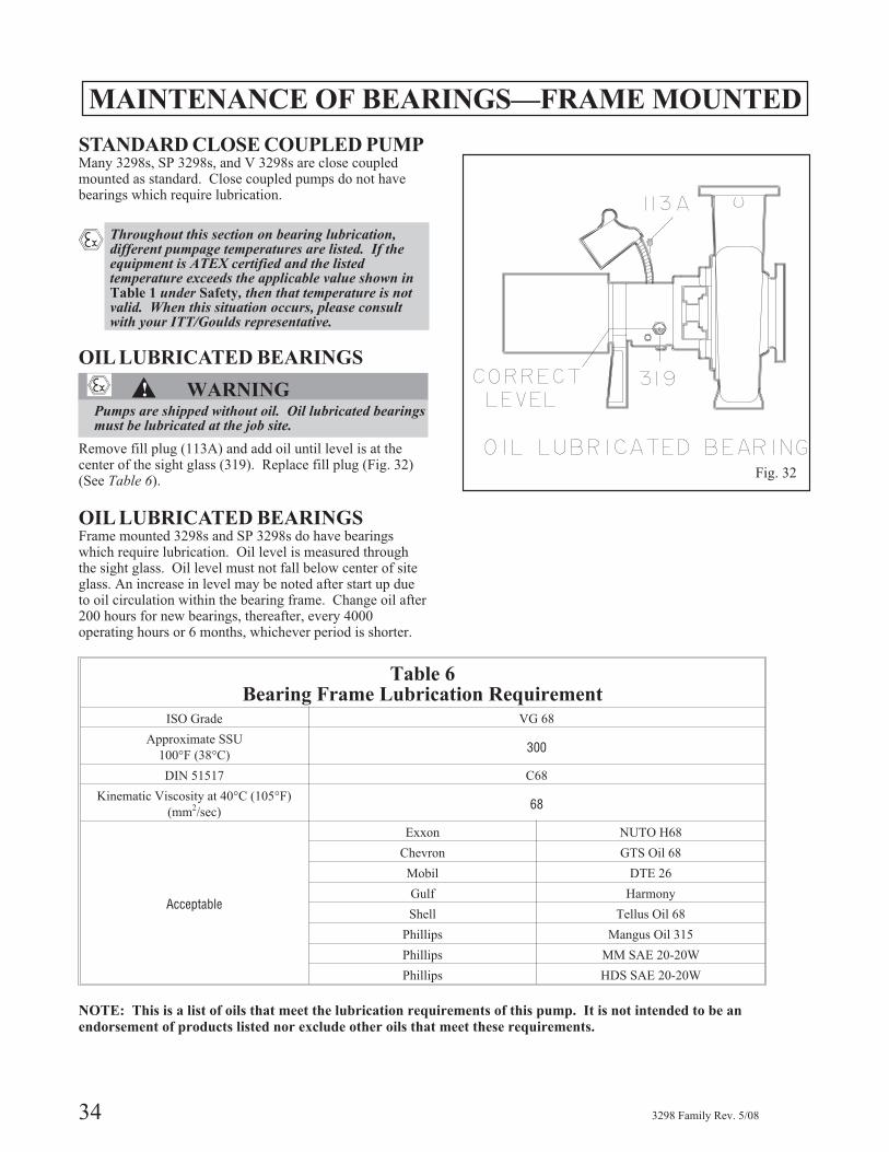
▲! WARNINGPumps are shipped without oil. Oil lubricated bearingsmust be lubricated at the job site.
Remove fill plug (113A) and add oil until level is at thecenter of the sight glass (319). Replace fill plug (Fig. 32)(See Table 6).
OIL LUBRICATED BEARINGSFrame mounted 3298s and SP 3298s do have bearingswhich require lubrication. Oil level is measured throughthe sight glass. Oil level must not fall below center of siteglass. An increase in level may be noted after start up dueto oil circulation within the bearing frame. Change oil after200 hours for new bearings, thereafter, every 4000operating hours or 6 months, whichever period is shorter.
34 3298 Family Rev. 5/08
Fig. 32
Table 6Bearing Frame Lubrication Requirement
ISO Grade VG 68
Approximate SSU
100°F (38°C)300
DIN 51517 C68
Kinematic Viscosity at 40°C (105°F)
(mm2/sec)68
Acceptable
Exxon NUTO H68
Chevron GTS Oil 68
Mobil DTE 26
Gulf Harmony
Shell Tellus Oil 68
Phillips Mangus Oil 315
Phillips MM SAE 20-20W
Phillips HDS SAE 20-20W
NOTE: This is a list of oils that meet the lubrication requirements of this pump. It is not intended to be an
endorsement of products listed nor exclude other oils that meet these requirements.

TROUBLESHOOTING
3298 Family Rev. 5/08 35
5
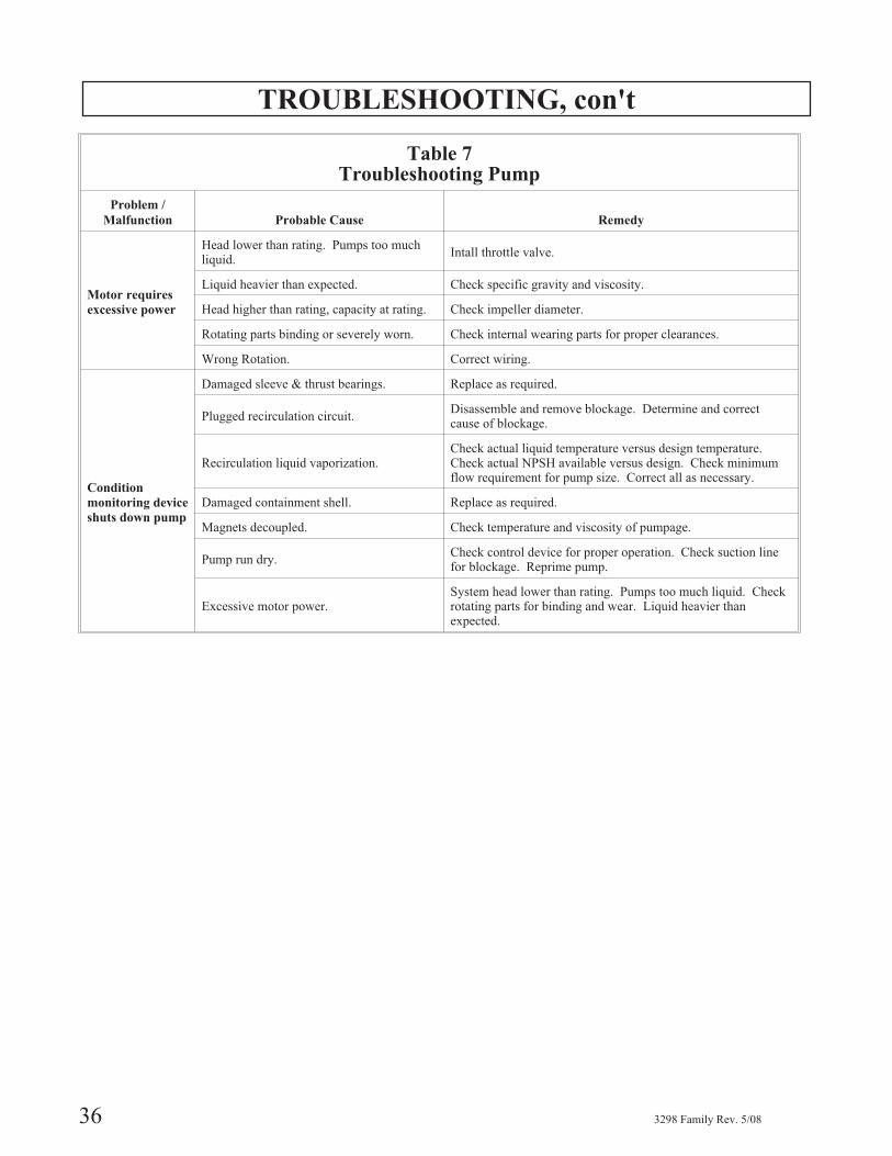
Table 7Troubleshooting Pump
Problem /
Malfunction Probable Cause Remedy
No liquid
delivered
Pump not primed.
3298-V 3298Reprime pump, check that pump and suctionline are full of liquid.
SP 3298
Add initial charge to casing.
Suction lift greater than maximum allowable- raise sump level.
Suction line clogged.Check suction line pressure. If low,locate and remove obstructions.
Impeller clogged with foreign material. Disassemble and remove blockage.
Magnet de-coupling.Shut down. Check temperature andviscosity of pumpage.
Pump not
producing rated
flow or head
Air leak in suction line. Check for leakage and correct.
Impeller partly clogged. Back flush pump to clean impeller.
Worn impeller rings. Replace defective part as required.
Insufficient suction head.Ensure that suction line shutoff valve isfully open and line is unobstructed.Check suction pressure.
Worn or broken impeller. Inspect and replace if necessary.
Wrong Rotation. Correct Wiring.
Pump starts then
stops pumping
Improperly primed pump. Reprime pump.
Air leak in suction line. Check for leakage and correct.
Magnet de-coupling.Shut down. Check temperature andviscosity of pumpage.
Air or vapor pockets in suction line.Rearrange piping as necessary, toeliminate air pockets.
Bearings run hot
Improper lubrication. Check lubricant for suitability and level.
Lube cooling. Check cooling system.
Improper alignment. Check pump alignment.
Pump is noisy or
vibrates
Improper pump / driver alignment. Align shafts.
Partly clogged impeller causing imbalance. Disassemble and remove blockage.
Broken or bent impeller or shaft. Replace as required.
Base not rigid enough.Tighten hold down bolts of pump and motor or adjust stilts.Check grout.
Suction or discharge piping not anchored orproperly supported.
Anchor per Hydraulic Institute Standards recommendations(Edition 14, centrigual pump section).
Pump is cavitating. Increase NPSH available.
TROUBLESHOOTING, con't
36 3298 Family Rev. 5/08
Table 7Troubleshooting Pump
Problem /
Malfunction Probable Cause Remedy
Motor requires
excessive power
Head lower than rating. Pumps too muchliquid.
Intall throttle valve.
Liquid heavier than expected. Check specific gravity and viscosity.
Head higher than rating, capacity at rating. Check impeller diameter.
Rotating parts binding or severely worn. Check internal wearing parts for proper clearances.
Wrong Rotation. Correct wiring.
Condition
monitoring device
shuts down pump
Damaged sleeve & thrust bearings. Replace as required.
Plugged recirculation circuit.Disassemble and remove blockage. Determine and correctcause of blockage.
Recirculation liquid vaporization.Check actual liquid temperature versus design temperature.Check actual NPSH available versus design. Check minimumflow requirement for pump size. Correct all as necessary.
Damaged containment shell. Replace as required.
Magnets decoupled. Check temperature and viscosity of pumpage.
Pump run dry.Check control device for proper operation. Check suction linefor blockage. Reprime pump.
Excessive motor power.System head lower than rating. Pumps too much liquid. Checkrotating parts for binding and wear. Liquid heavier thanexpected.
3298 Family Rev. 5/08 37
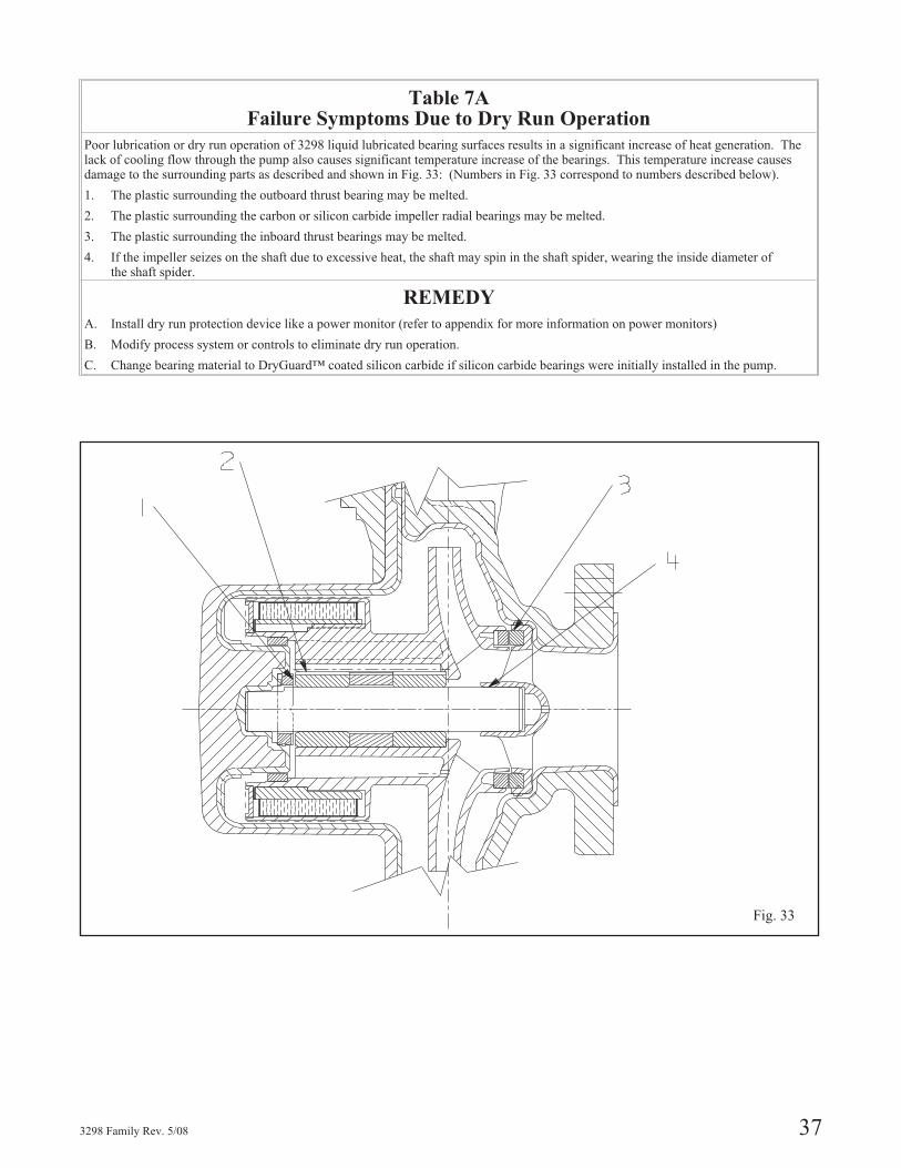
Fig. 33
Table 7AFailure Symptoms Due to Dry Run Operation
Poor lubrication or dry run operation of 3298 liquid lubricated bearing surfaces results in a significant increase of heat generation. Thelack of cooling flow through the pump also causes significant temperature increase of the bearings. This temperature increase causesdamage to the surrounding parts as described and shown in Fig. 33: (Numbers in Fig. 33 correspond to numbers described below).
1. The plastic surrounding the outboard thrust bearing may be melted.
2. The plastic surrounding the carbon or silicon carbide impeller radial bearings may be melted.
3. The plastic surrounding the inboard thrust bearings may be melted.
4. If the impeller seizes on the shaft due to excessive heat, the shaft may spin in the shaft spider, wearing the inside diameter ofthe shaft spider.
REMEDY
A. Install dry run protection device like a power monitor (refer to appendix for more information on power monitors)
B. Modify process system or controls to eliminate dry run operation.
C. Change bearing material to DryGuard™ coated silicon carbide if silicon carbide bearings were initially installed in the pump.

38 3298 Family Rev. 5/08
DISASSEMBLY& REASSEMBLY
REQUIRED TOOLS . . . . . . . . . . . . . . . . . . . . . . . . . . . . 39
PREPARATION FOR DISASSEMBLY . . . . . . . . . . . . . . . . . 47
DISASSEMBLY
3298 XS Group . . . . . . . . . . . . . . . . . . . . . . . . . . . . . . 48
3298 S Group . . . . . . . . . . . . . . . . . . . . . . . . . . . . . . . 50
3298 M Group . . . . . . . . . . . . . . . . . . . . . . . . . . . . . . 53
3298 L Group. . . . . . . . . . . . . . . . . . . . . . . . . . . . . . . 56
SP 3298 . . . . . . . . . . . . . . . . . . . . . . . . . . . . . . . . . . 59
V 3298 . . . . . . . . . . . . . . . . . . . . . . . . . . . . . . . . . . 62
INSPECTIONS . . . . . . . . . . . . . . . . . . . . . . . . . . . . . . . 64
REASSEMBLY
3298 XS Group . . . . . . . . . . . . . . . . . . . . . . . . . . . . . . 66
3298 S Group . . . . . . . . . . . . . . . . . . . . . . . . . . . . . . . 69
3298 M Group . . . . . . . . . . . . . . . . . . . . . . . . . . . . . . 73
3298 L Group. . . . . . . . . . . . . . . . . . . . . . . . . . . . . . . 78
SP 3298 . . . . . . . . . . . . . . . . . . . . . . . . . . . . . . . . . . 84
V 3298 . . . . . . . . . . . . . . . . . . . . . . . . . . . . . . . . . . 89
SECTIONALS, PARTS LIST,
MATERIALS OF CONSTRUCTION . . . . . . . . . . . . . . . . 92-112
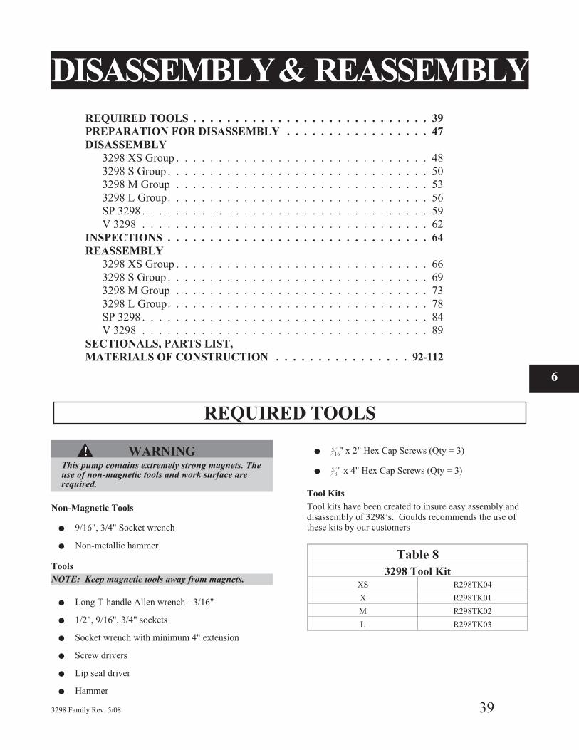
REQUIRED TOOLS
▲! WARNINGThis pump contains extremely strong magnets. Theuse of non-magnetic tools and work surface arerequired.
Non-Magnetic Tools
� 9/16", 3/4" Socket wrench
� Non-metallic hammer
Tools
NOTE: Keep magnetic tools away from magnets.
� Long T-handle Allen wrench - 3/16"
� 1/2", 9/16", 3/4" sockets
� Socket wrench with minimum 4" extension
� Screw drivers
� Lip seal driver
� Hammer
�5
16" x 2" Hex Cap Screws (Qty = 3)
�5
8" x 4" Hex Cap Screws (Qty = 3)
Tool Kits
Tool kits have been created to insure easy assembly anddisassembly of 3298’s. Goulds recommends the use ofthese kits by our customers
Table 8
3298 Tool KitXS R298TK04
X R298TK01
M R298TK02
L R298TK03
3298 Family Rev. 5/08 39
6
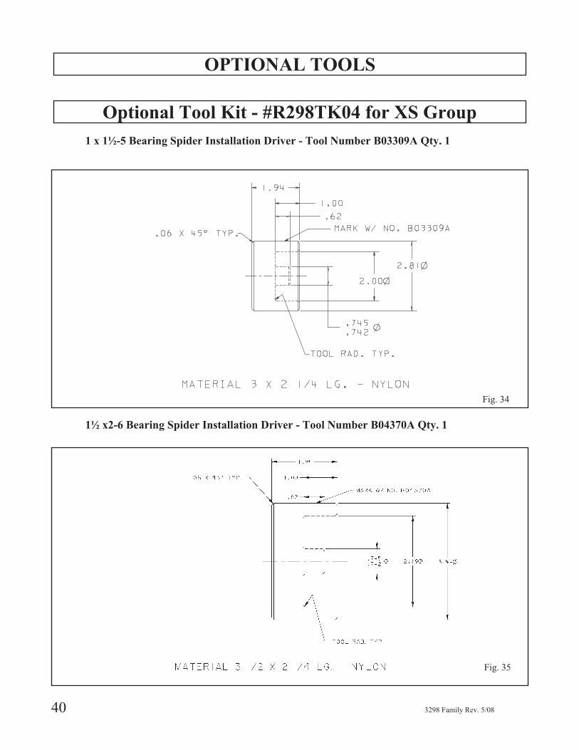
OPTIONAL TOOLS
Optional Tool Kit - #R298TK04 for XS Group
1 x 1½-5 Bearing Spider Installation Driver - Tool Number B03309A Qty. 1
1½ x2-6 Bearing Spider Installation Driver - Tool Number B04370A Qty. 1
40 3298 Family Rev. 5/08
Fig. 34
Fig. 35
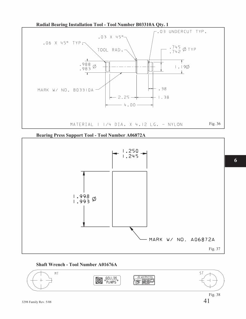
Radial Bearing Installation Tool - Tool Number B03310A Qty. 1
Bearing Press Support Tool - Tool Number A06872A
Shaft Wrench - Tool Number A01676A
3298 Family Rev. 5/08 41
6
Fig. 38
Fig. 36
Fig. 37
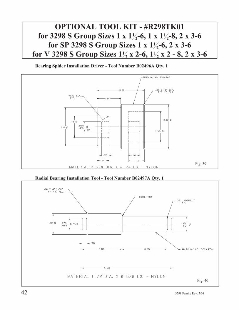
OPTIONAL TOOL KIT - #R298TK01
for 3298 S Group Sizes 1 x 112-6, 1 x 11
2-8, 2 x 3-6
for SP 3298 S Group Sizes 1 x 112-6, 2 x 3-6
for V 3298 S Group Sizes 112 x 2-6, 11
2 x 2 - 8, 2 x 3-6
Bearing Spider Installation Driver - Tool Number B02496A Qty. 1
Radial Bearing Installation Tool - Tool Number B02497A Qty. 1
42 3298 Family Rev. 5/08
Fig. 39
Fig. 40
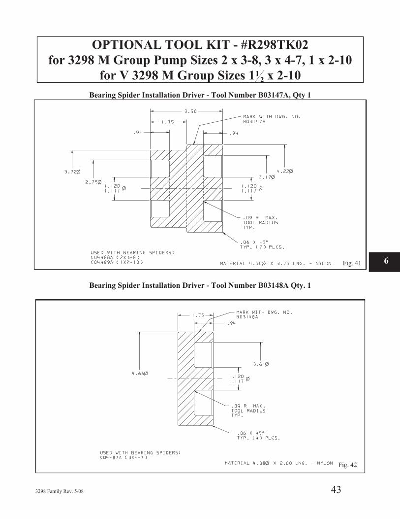
OPTIONAL TOOL KIT - #R298TK02
for 3298 M Group Pump Sizes 2 x 3-8, 3 x 4-7, 1 x 2-10
for V 3298 M Group Sizes 112 x 2-10
Bearing Spider Installation Driver - Tool Number B03147A, Qty 1
Bearing Spider Installation Driver - Tool Number B03148A Qty. 1
3298 Family Rev. 5/08 43
Fig. 41 6
Fig. 42
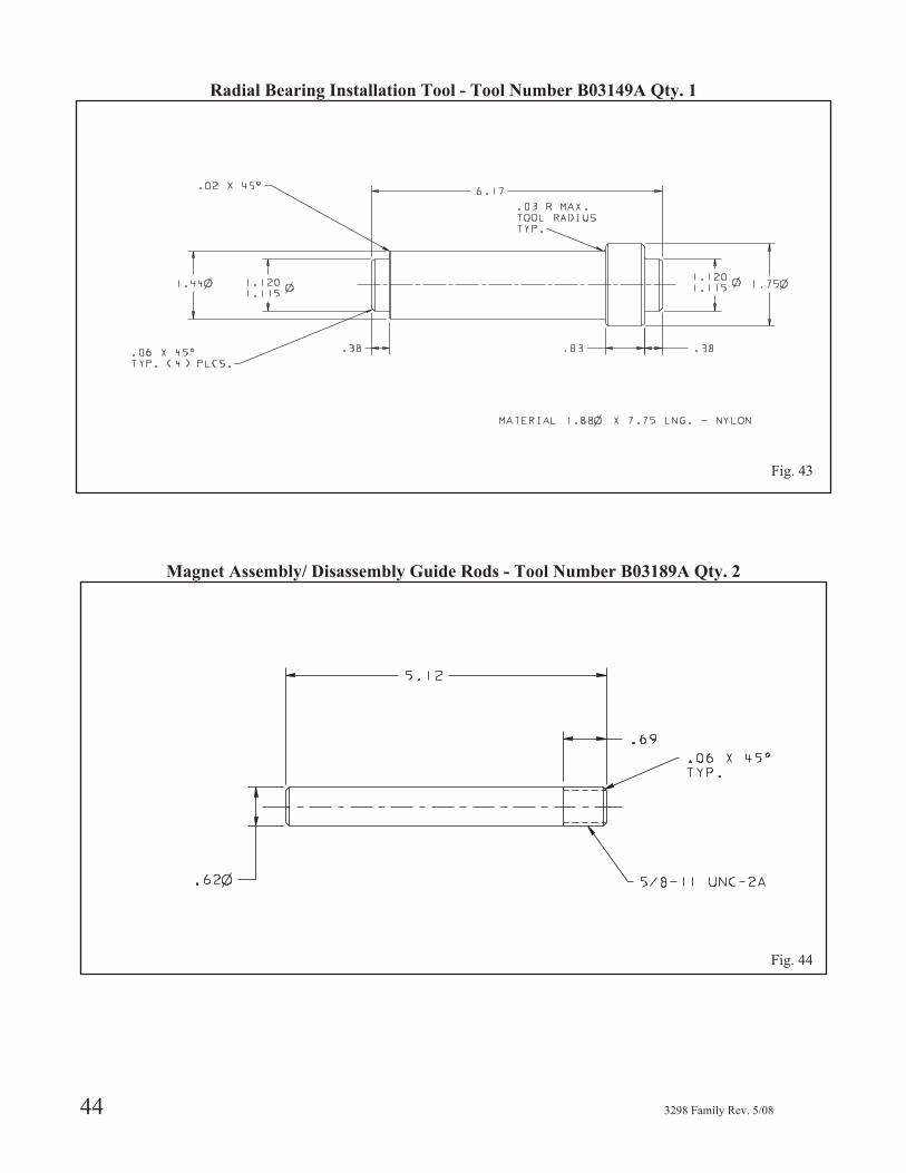
Radial Bearing Installation Tool - Tool Number B03149A Qty. 1
Magnet Assembly/ Disassembly Guide Rods - Tool Number B03189A Qty. 2
44 3298 Family Rev. 5/08
Fig. 43
Fig. 44

OPTIONAL TOOL KIT - #R298TK03
for L Group Pump Sizes 3 x 4-10, 4 x 6-10
Bearing Spider Installation Driver - Tool Number B03191A Qty. 1
Radial Bearing Installation Tool - Tool Number B03175A Qty. 1
3298 Family Rev. 5/08 45
6Fig. 45
Fig. 46
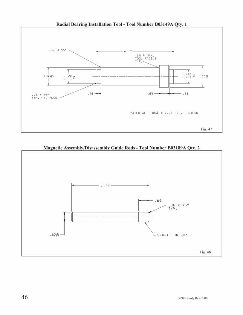
Radial Bearing Installation Tool - Tool Number B03149A Qty. 1
Magnetic Assembly/Disassembly Guide Rods - Tool Number B03189A Qty. 2
46 3298 Family Rev. 5/08
Fig. 47
Fig. 48
PREPARATION FOR DISASSEMBLY
� A build up of gases within the pump, sealingsystem and or process piping system may result inan explosive environment within the pump orprocess piping system. Ensure process pipingsystem, pump, and sealing system are properlyvented prior to operation.
▲! WARNINGThe 3298 family of pumps often handles hazardousand/or toxic fluids. Skin, eye and respiratoryprotection required. Precautions must be taken toprevent injury or environmental contamination.Drain and decontaminate pump in accordance withall federal, state, local, and company regulations.
� Leakage of process liquid may result in creating anexplosive atmosphere. Follow all pump and sealassembly procedures.
1. Lock out power to driver.
2. Shut off all valves controlling flow to and from pump.
3. The pump should be drained and flushed before it is
removed from the piping. After isolating the pump
from the system, flush the pump using a compatible
liquid.
▲! WARNINGFailure to properly lift and support equipment couldresult in serious injury or damage to pumps.
▲! WARNINGEnsure pump is isolated from system and pressure isrelieved before any plugs are removed or pipingdisconnected.
4. Disconnect all piping and auxiliary equipment.
5. Remove coupling guard (For frame mounted
version).
6. Remove coupling (For frame mounted version).
7. Remove casing foot and frame / C-face motor support
foot bolts.
8. Remove pump from baseplate.
9. Drain Oil from frame mounted pump.
DECONTAMINATION PROCEDURE10. Connect clean flush liquid supply to discharge
nozzle.
11. Devise a means of collecting flush liquid as it drains
out the drain connection.
12. Flush to remove residue.
3298 Family Rev. 5/08 47
6

DISASSEMBLY
3298 XS GROUP DISASSEMBLY
▲! WARNINGEach component must be individually decontami-nated using procedures in accordance with allfederal, state, local, and company environmentalregulations.
▲! WARNINGThe magnets contained in this unit are extremelypowerful. Keep magnetic drive components andmagnetic tools apart from each other by a minimumof three (3) feet [one (1) meter]. Serious injury tofingers and hands will result.
NOTE: When working on pump, use a bench with anon-magnetic work surface such as wood or brasssurface.
� CAUTION
The shop area must be clean and free of any sub-stances that would contaminate the magnets, ex.ferrous metals.
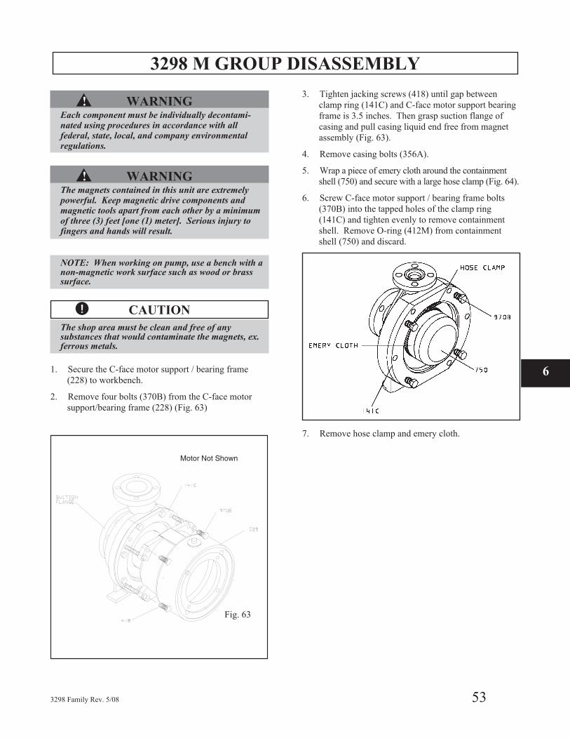
1. Secure the C-face motor support (228) to workbench.
2. Remove 4 bolts (370B) from the C-face motor
support (228) (Fig. 49).
3. Grasp suction flange of casing and pull casing liquid
end free from magnet assembly (Fig. 49).
4. Remove casing bolts (356A) (Fig. 49).
5. Wrap a piece of emery cloth around the containment
shell (750) and secure with a large hose clamp (Fig. 50).
6. Screw C-face motor support bolts (370B) into the
tapped holes of the clamp ring (141C) and tighten
evenly to remove containment shell. Remove O-ring
(412M) from containment shell (750) and discard.
7. Remove hose clamp and emery cloth.
48 3298 Family Rev. 5/08
Fig. 49
Fig. 50
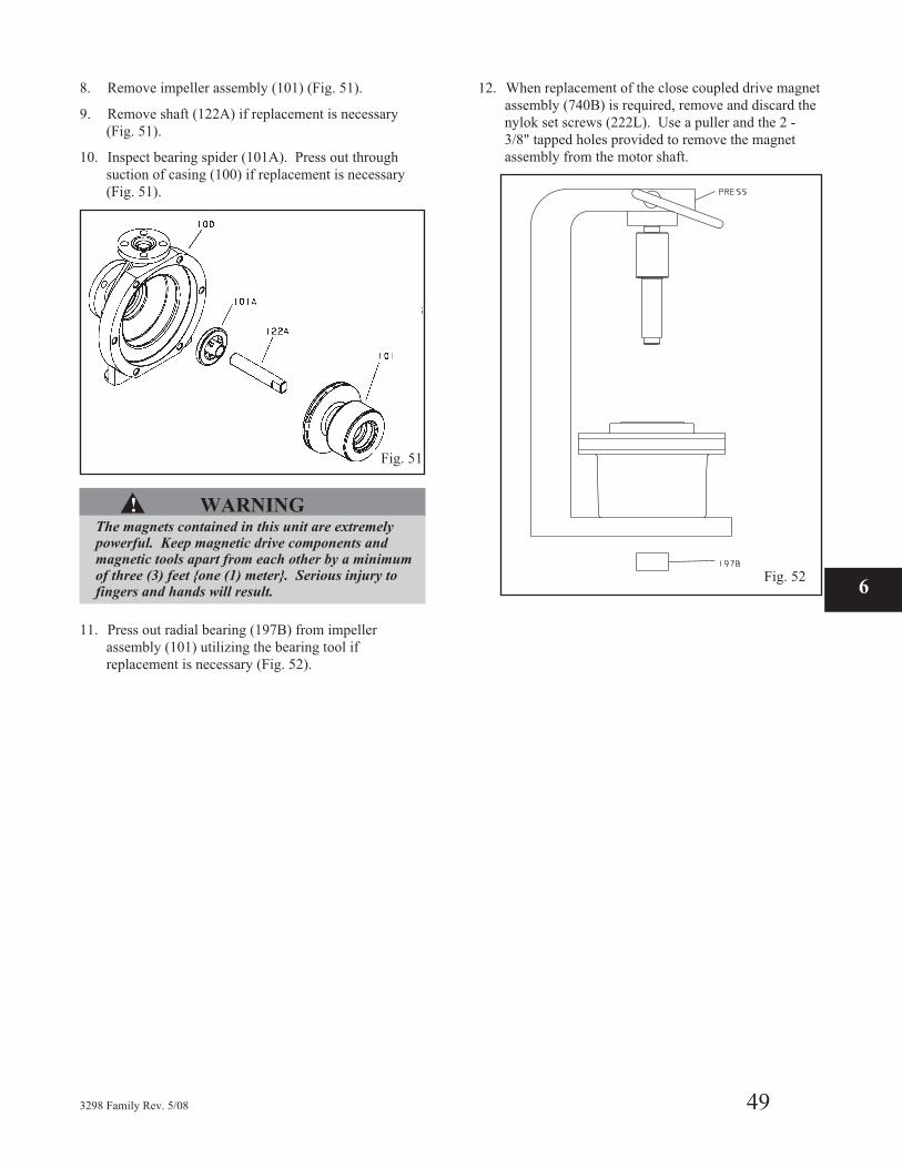
8. Remove impeller assembly (101) (Fig. 51).
9. Remove shaft (122A) if replacement is necessary
(Fig. 51).
10. Inspect bearing spider (101A). Press out through
suction of casing (100) if replacement is necessary
(Fig. 51).
▲! WARNINGThe magnets contained in this unit are extremelypowerful. Keep magnetic drive components andmagnetic tools apart from each other by a minimumof three (3) feet {one (1) meter}. Serious injury tofingers and hands will result.
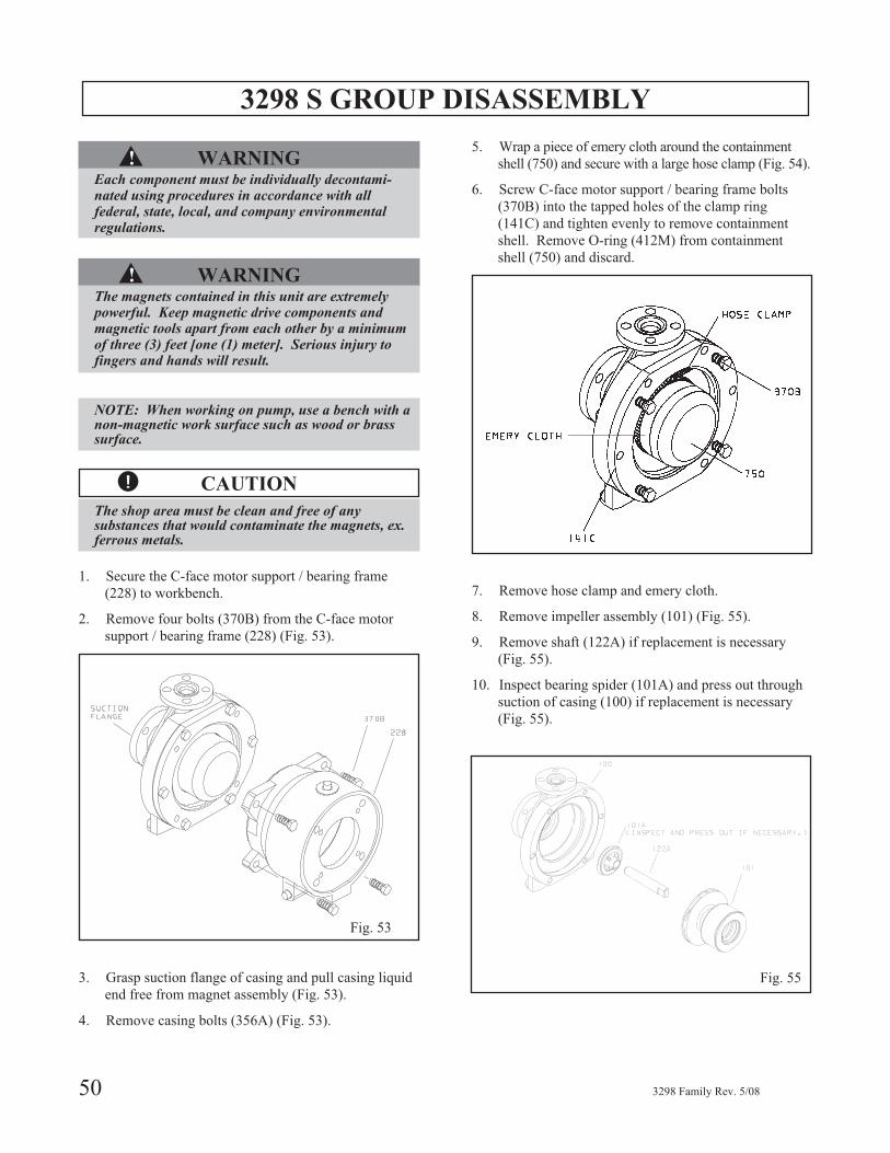
11. Press out radial bearing (197B) from impeller
assembly (101) utilizing the bearing tool if
replacement is necessary (Fig. 52).
12. When replacement of the close coupled drive magnet
assembly (740B) is required, remove and discard the
nylok set screws (222L). Use a puller and the 2 -
3/8" tapped holes provided to remove the magnet
assembly from the motor shaft.
3298 Family Rev. 5/08 49
6Fig. 52
Fig. 51
3298 S GROUP DISASSEMBLY
▲! WARNINGEach component must be individually decontami-nated using procedures in accordance with allfederal, state, local, and company environmentalregulations.
▲! WARNINGThe magnets contained in this unit are extremelypowerful. Keep magnetic drive components andmagnetic tools apart from each other by a minimumof three (3) feet [one (1) meter]. Serious injury tofingers and hands will result.
NOTE: When working on pump, use a bench with anon-magnetic work surface such as wood or brasssurface.
� CAUTION
The shop area must be clean and free of anysubstances that would contaminate the magnets, ex.ferrous metals.
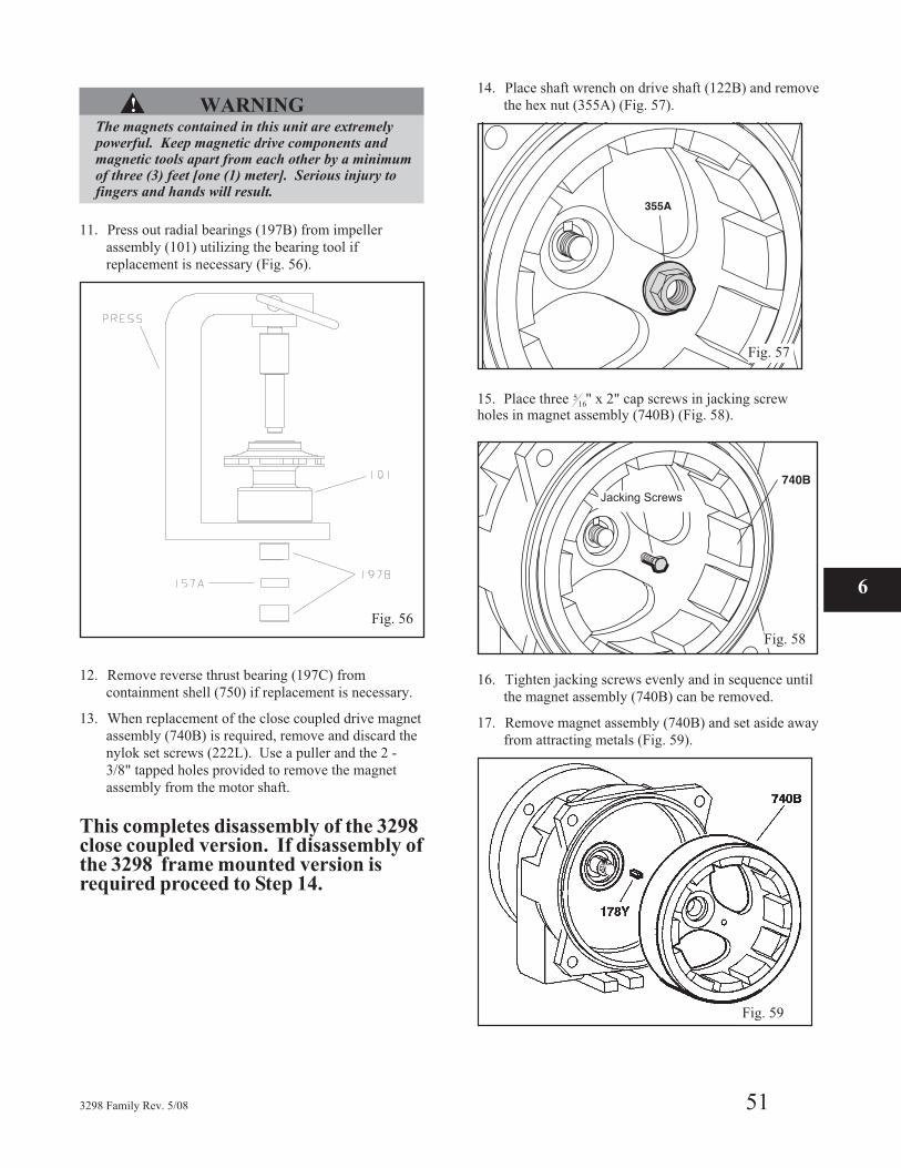
1. Secure the C-face motor support / bearing frame
(228) to workbench.
2. Remove four bolts (370B) from the C-face motor
support / bearing frame (228) (Fig. 53).
3. Grasp suction flange of casing and pull casing liquid
end free from magnet assembly (Fig. 53).
4. Remove casing bolts (356A) (Fig. 53).
5. Wrap a piece of emery cloth around the containment
shell (750) and secure with a large hose clamp (Fig. 54).
6. Screw C-face motor support / bearing frame bolts
(370B) into the tapped holes of the clamp ring
(141C) and tighten evenly to remove containment
shell. Remove O-ring (412M) from containment
shell (750) and discard.
7. Remove hose clamp and emery cloth.
8. Remove impeller assembly (101) (Fig. 55).
9. Remove shaft (122A) if replacement is necessary
(Fig. 55).
10. Inspect bearing spider (101A) and press out through
suction of casing (100) if replacement is necessary
(Fig. 55).
50 3298 Family Rev. 5/08
Fig. 53
Fig. 54
Fig. 55
▲! WARNINGThe magnets contained in this unit are extremelypowerful. Keep magnetic drive components andmagnetic tools apart from each other by a minimumof three (3) feet [one (1) meter]. Serious injury tofingers and hands will result.
11. Press out radial bearings (197B) from impeller
assembly (101) utilizing the bearing tool if
replacement is necessary (Fig. 56).
12. Remove reverse thrust bearing (197C) from
containment shell (750) if replacement is necessary.
13. When replacement of the close coupled drive magnet
assembly (740B) is required, remove and discard the
nylok set screws (222L). Use a puller and the 2 -
3/8" tapped holes provided to remove the magnet
assembly from the motor shaft.
This completes disassembly of the 3298close coupled version. If disassembly ofthe 3298 frame mounted version isrequired proceed to Step 14.
14. Place shaft wrench on drive shaft (122B) and remove
the hex nut (355A) (Fig. 57).
15. Place three 516" x 2" cap screws in jacking screw
holes in magnet assembly (740B) (Fig. 58).
16. Tighten jacking screws evenly and in sequence until
the magnet assembly (740B) can be removed.
17. Remove magnet assembly (740B) and set aside away
from attracting metals (Fig. 59).
3298 Family Rev. 5/08 51
Fig. 56
Fig. 58
Jacking Screws
6
Fig. 57
Fig. 59
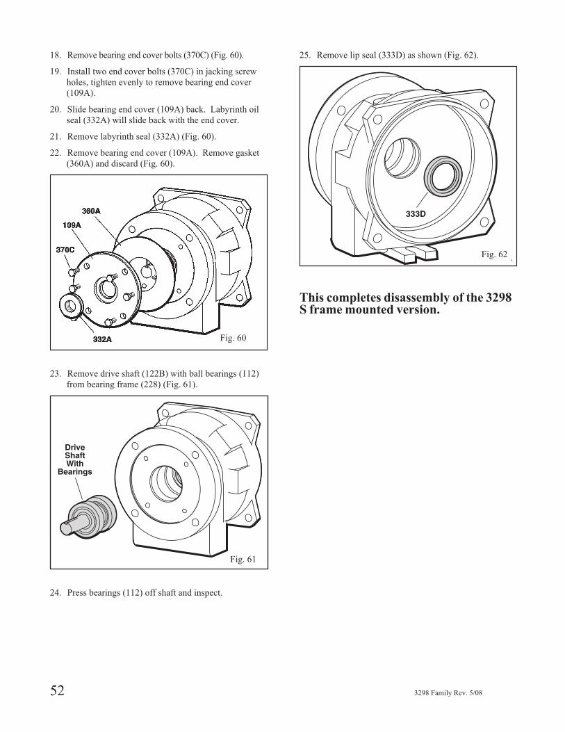
18. Remove bearing end cover bolts (370C) (Fig. 60).
19. Install two end cover bolts (370C) in jacking screw
holes, tighten evenly to remove bearing end cover
(109A).
20. Slide bearing end cover (109A) back. Labyrinth oil
seal (332A) will slide back with the end cover.
21. Remove labyrinth seal (332A) (Fig. 60).
22. Remove bearing end cover (109A). Remove gasket
(360A) and discard (Fig. 60).
23. Remove drive shaft (122B) with ball bearings (112)
from bearing frame (228) (Fig. 61).
24. Press bearings (112) off shaft and inspect.
25. Remove lip seal (333D) as shown (Fig. 62).
This completes disassembly of the 3298S frame mounted version.
52 3298 Family Rev. 5/08
Fig. 62
Fig. 61
Fig. 60
3298 M GROUP DISASSEMBLY
▲! WARNINGEach component must be individually decontami-nated using procedures in accordance with allfederal, state, local, and company environmentalregulations.
▲! WARNINGThe magnets contained in this unit are extremelypowerful. Keep magnetic drive components andmagnetic tools apart from each other by a minimumof three (3) feet [one (1) meter]. Serious injury tofingers and hands will result.
NOTE: When working on pump, use a bench with anon-magnetic work surface such as wood or brasssurface.
� CAUTION
The shop area must be clean and free of anysubstances that would contaminate the magnets, ex.ferrous metals.
1. Secure the C-face motor support / bearing frame
(228) to workbench.
2. Remove four bolts (370B) from the C-face motor
support/bearing frame (228) (Fig. 63)
3. Tighten jacking screws (418) until gap between
clamp ring (141C) and C-face motor support bearing
frame is 3.5 inches. Then grasp suction flange of
casing and pull casing liquid end free from magnet
assembly (Fig. 63).
4. Remove casing bolts (356A).
5. Wrap a piece of emery cloth around the containment
shell (750) and secure with a large hose clamp (Fig. 64).
6. Screw C-face motor support / bearing frame bolts
(370B) into the tapped holes of the clamp ring
(141C) and tighten evenly to remove containment
shell. Remove O-ring (412M) from containment
shell (750) and discard.
7. Remove hose clamp and emery cloth.
3298 Family Rev. 5/08 53
Motor Not Shown
6
Fig. 64
Fig. 63
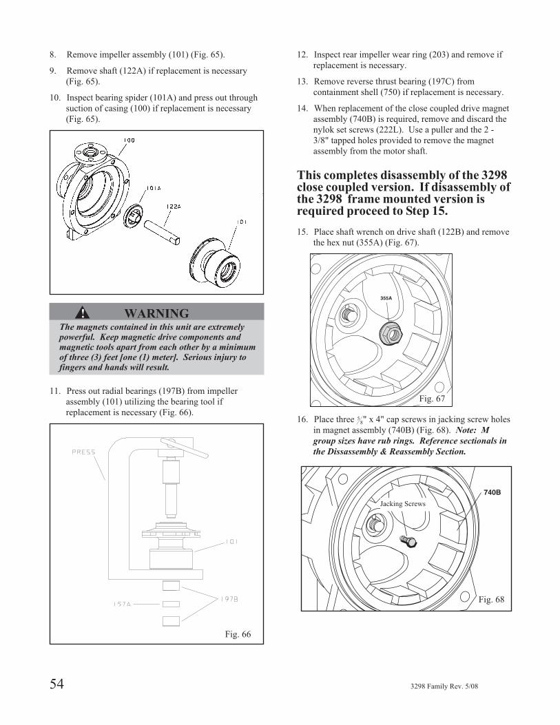
8. Remove impeller assembly (101) (Fig. 65).
9. Remove shaft (122A) if replacement is necessary
(Fig. 65).
10. Inspect bearing spider (101A) and press out through
suction of casing (100) if replacement is necessary
(Fig. 65).
▲! WARNINGThe magnets contained in this unit are extremelypowerful. Keep magnetic drive components andmagnetic tools apart from each other by a minimumof three (3) feet [one (1) meter]. Serious injury tofingers and hands will result.
11. Press out radial bearings (197B) from impeller
assembly (101) utilizing the bearing tool if
replacement is necessary (Fig. 66).
12. Inspect rear impeller wear ring (203) and remove if
replacement is necessary.
13. Remove reverse thrust bearing (197C) from
containment shell (750) if replacement is necessary.
14. When replacement of the close coupled drive magnet
assembly (740B) is required, remove and discard the
nylok set screws (222L). Use a puller and the 2 -
3/8" tapped holes provided to remove the magnet
assembly from the motor shaft.
This completes disassembly of the 3298close coupled version. If disassembly ofthe 3298 frame mounted version isrequired proceed to Step 15.
15. Place shaft wrench on drive shaft (122B) and remove
the hex nut (355A) (Fig. 67).
16. Place three 58" x 4" cap screws in jacking screw holes
in magnet assembly (740B) (Fig. 68). Note: M
group sizes have rub rings. Reference sectionals in
the Dissassembly & Reassembly Section.
54 3298 Family Rev. 5/08
Fig. 65
Fig. 67
Fig. 68
Jacking Screws
Fig. 66
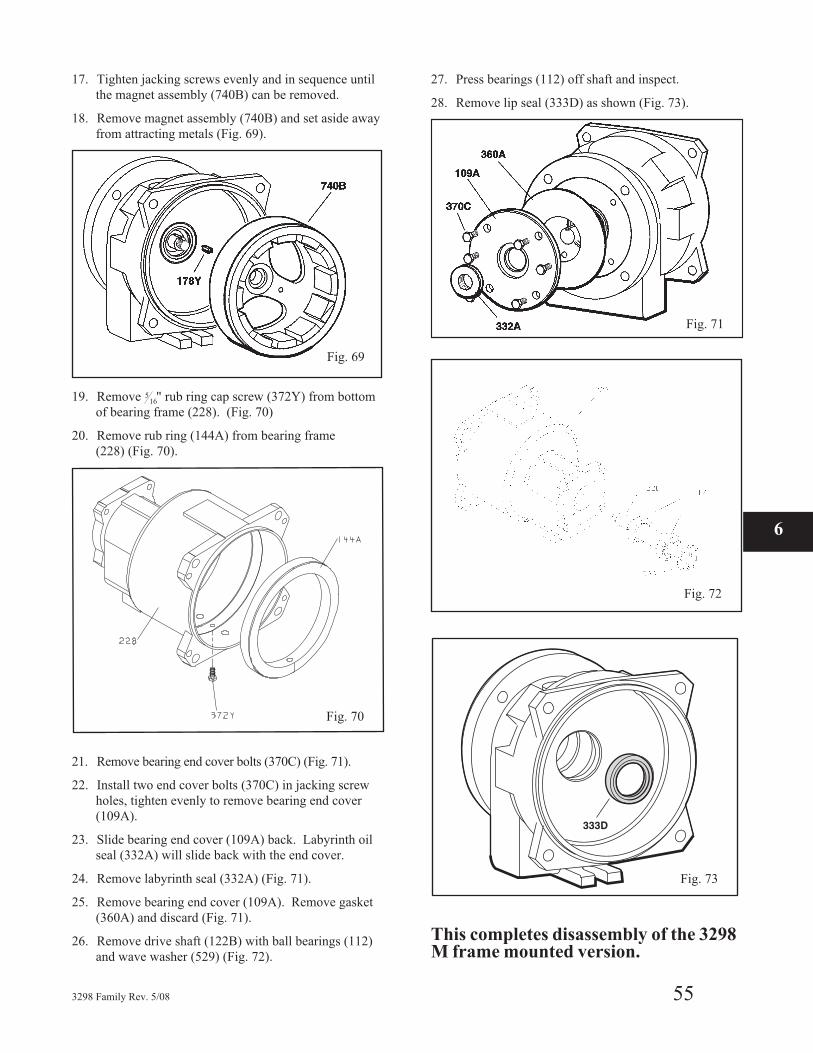
17. Tighten jacking screws evenly and in sequence until
the magnet assembly (740B) can be removed.
18. Remove magnet assembly (740B) and set aside away
from attracting metals (Fig. 69).
19. Remove 516" rub ring cap screw (372Y) from bottom
of bearing frame (228). (Fig. 70)
20. Remove rub ring (144A) from bearing frame
(228) (Fig. 70).
21. Remove bearing end cover bolts (370C) (Fig. 71).
22. Install two end cover bolts (370C) in jacking screw
holes, tighten evenly to remove bearing end cover
(109A).
23. Slide bearing end cover (109A) back. Labyrinth oil
seal (332A) will slide back with the end cover.
24. Remove labyrinth seal (332A) (Fig. 71).
25. Remove bearing end cover (109A). Remove gasket
(360A) and discard (Fig. 71).
26. Remove drive shaft (122B) with ball bearings (112)
and wave washer (529) (Fig. 72).
27. Press bearings (112) off shaft and inspect.
28. Remove lip seal (333D) as shown (Fig. 73).
This completes disassembly of the 3298M frame mounted version.
3298 Family Rev. 5/08 55
Fig. 69
6
Fig. 70
Fig. 71
Fig. 72
Fig. 73
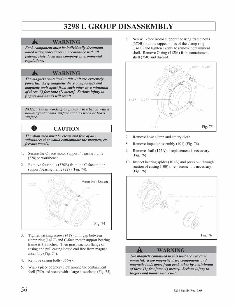
3298 L GROUP DISASSEMBLY
▲! WARNINGEach component must be individually decontami-nated using procedures in accordance with allfederal, state, local and company environmentalregulations.
▲! WARNINGThe magnets contained in this unit are extremelypowerful. Keep magnetic drive components andmagnetic tools apart from each other by a minimumof three (3) feet [one (1) meter]. Serious injury tofingers and hands will result.
NOTE: When working on pump, use a bench with anon-magnetic work surface such as wood or brasssurface.
� CAUTION
The shop area must be clean and free of anysubstances that would contaminate the magnets, ex.ferrous metals.
1. Secure the C-face motor support / bearing frame
(228) to workbench.
2. Remove four bolts (370B) from the C-face motor
support/bearing frame (228) (Fig. 74).
3. Tighten jacking screws (418) until gap between
clamp ring (141C) and C-face motor support bearing
frame is 3.5 inches. Then grasp suction flange of
casing and pull casing liquid end free from magnet
assembly (Fig. 74).
4. Remove casing bolts (356A).
5. Wrap a piece of emery cloth around the containment
shell (750) and secure with a large hose clamp (Fig. 75).
6. Screw C-face motor support / bearing frame bolts
(370B) into the tapped holes of the clamp ring
(141C) and tighten evenly to remove containment
shell. Remove O-ring (412M) from containment
shell (750) and discard.
7. Remove hose clamp and emery cloth.
8. Remove impeller assembly (101) (Fig. 76).
9. Remove shaft (122A) if replacement is necessary
(Fig. 76).
10. Inspect bearing spider (101A) and press out through
suction of casing (100) if replacement is necessary
(Fig. 76).
▲! WARNINGThe magnets contained in this unit are extremelypowerful. Keep magnetic drive components andmagnetic tools apart from each other by a minimumof three (3) feet [one (1) meter]. Serious injury tofingers and hands will result.
56 3298 Family Rev. 5/08
Motor Not Shown
Fig. 74
Fig. 75
Fig. 74
Fig. 75
Fig. 76
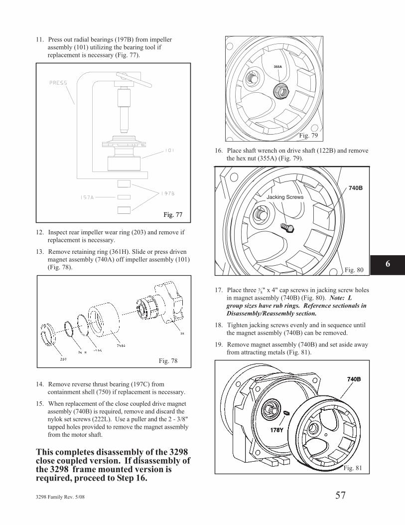
11. Press out radial bearings (197B) from impeller
assembly (101) utilizing the bearing tool if
replacement is necessary (Fig. 77).
12. Inspect rear impeller wear ring (203) and remove if
replacement is necessary.
13. Remove retaining ring (361H). Slide or press driven
magnet assembly (740A) off impeller assembly (101)
(Fig. 78).
14. Remove reverse thrust bearing (197C) from
containment shell (750) if replacement is necessary.
15. When replacement of the close coupled drive magnet
assembly (740B) is required, remove and discard the
nylok set screws (222L). Use a puller and the 2 - 3/8"
tapped holes provided to remove the magnet assembly
from the motor shaft.
This completes disassembly of the 3298close coupled version. If disassembly ofthe 3298 frame mounted version isrequired, proceed to Step 16.
16. Place shaft wrench on drive shaft (122B) and remove
the hex nut (355A) (Fig. 79).
17. Place three 58" x 4" cap screws in jacking screw holes
in magnet assembly (740B) (Fig. 80). Note: L
group sizes have rub rings. Reference sectionals in
Disassembly/Reassembly section.
18. Tighten jacking screws evenly and in sequence until
the magnet assembly (740B) can be removed.
19. Remove magnet assembly (740B) and set aside away
from attracting metals (Fig. 81).
3298 Family Rev. 5/08 57
Fig. 78
6
Fig. 77
Fig. 79
Fig. 80
Jacking Screws
Fig. 81
Fig. 77
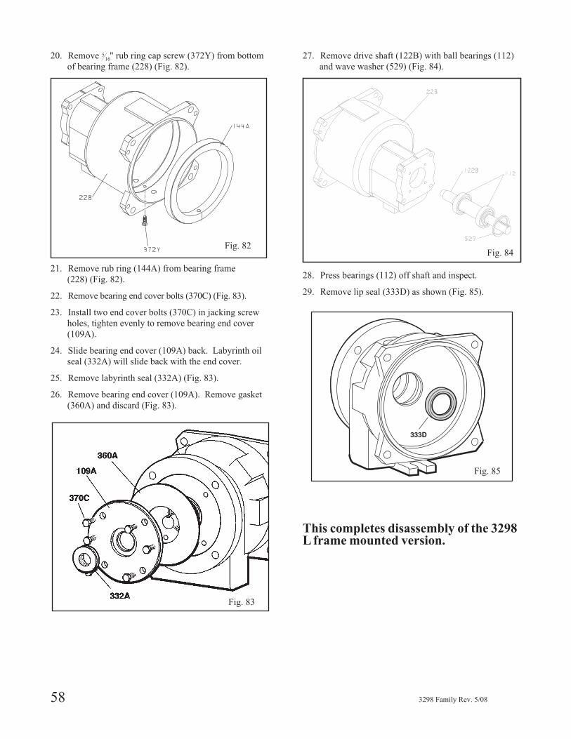
20. Remove 516" rub ring cap screw (372Y) from bottom
of bearing frame (228) (Fig. 82).
21. Remove rub ring (144A) from bearing frame
(228) (Fig. 82).
22. Remove bearing end cover bolts (370C) (Fig. 83).
23. Install two end cover bolts (370C) in jacking screw
holes, tighten evenly to remove bearing end cover
(109A).
24. Slide bearing end cover (109A) back. Labyrinth oil
seal (332A) will slide back with the end cover.
25. Remove labyrinth seal (332A) (Fig. 83).
26. Remove bearing end cover (109A). Remove gasket
(360A) and discard (Fig. 83).
27. Remove drive shaft (122B) with ball bearings (112)
and wave washer (529) (Fig. 84).
28. Press bearings (112) off shaft and inspect.
29. Remove lip seal (333D) as shown (Fig. 85).
This completes disassembly of the 3298L frame mounted version.
58 3298 Family Rev. 5/08
Fig. 82
Fig. 83
Fig. 85
Fig. 84Fig. 84
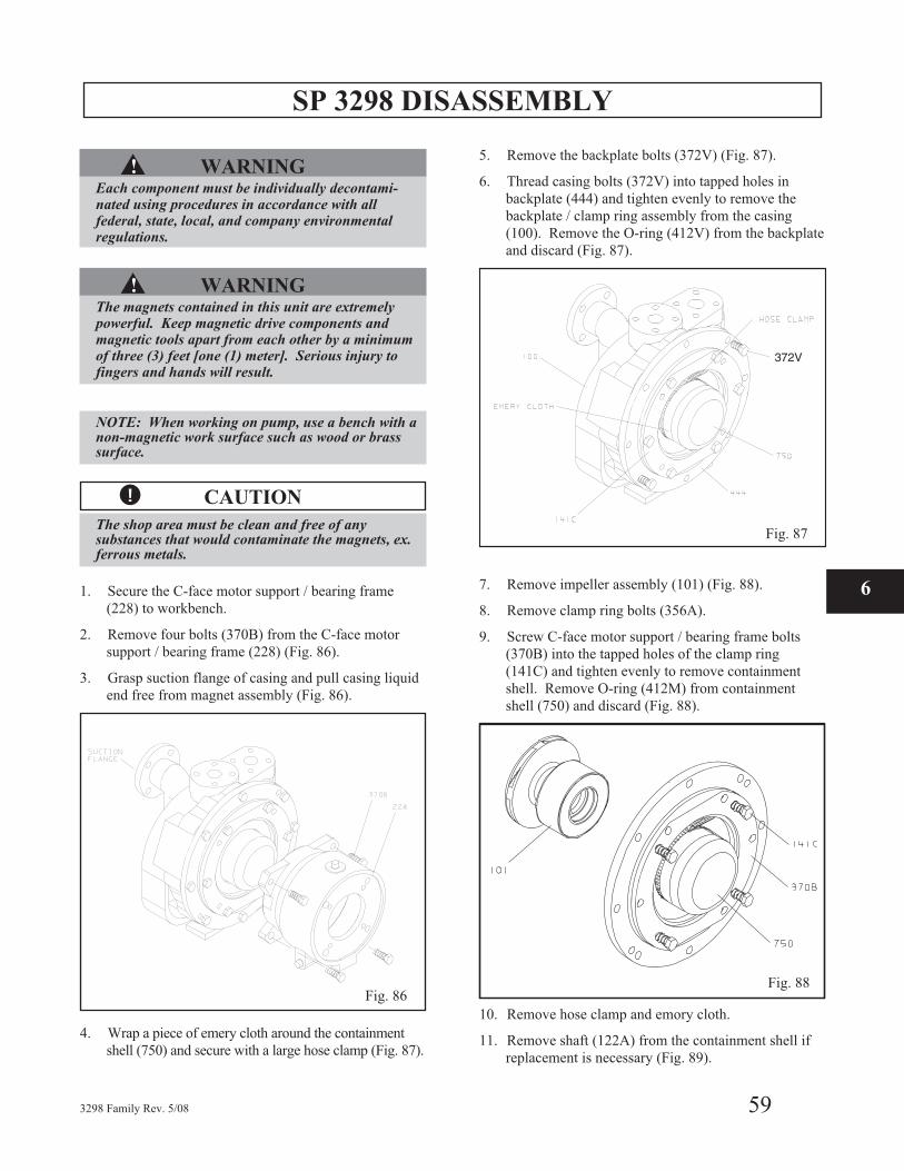
SP 3298 DISASSEMBLY
▲! WARNINGEach component must be individually decontami-nated using procedures in accordance with allfederal, state, local, and company environmentalregulations.
▲! WARNINGThe magnets contained in this unit are extremelypowerful. Keep magnetic drive components andmagnetic tools apart from each other by a minimumof three (3) feet [one (1) meter]. Serious injury tofingers and hands will result.
NOTE: When working on pump, use a bench with anon-magnetic work surface such as wood or brasssurface.
� CAUTION
The shop area must be clean and free of anysubstances that would contaminate the magnets, ex.ferrous metals.
1. Secure the C-face motor support / bearing frame
(228) to workbench.
2. Remove four bolts (370B) from the C-face motor
support / bearing frame (228) (Fig. 86).
3. Grasp suction flange of casing and pull casing liquid
end free from magnet assembly (Fig. 86).
4. Wrap a piece of emery cloth around the containment
shell (750) and secure with a large hose clamp (Fig. 87).
5. Remove the backplate bolts (372V) (Fig. 87).
6. Thread casing bolts (372V) into tapped holes in
backplate (444) and tighten evenly to remove the
backplate / clamp ring assembly from the casing
(100). Remove the O-ring (412V) from the backplate
and discard (Fig. 87).
7. Remove impeller assembly (101) (Fig. 88).
8. Remove clamp ring bolts (356A).
9. Screw C-face motor support / bearing frame bolts
(370B) into the tapped holes of the clamp ring
(141C) and tighten evenly to remove containment
shell. Remove O-ring (412M) from containment
shell (750) and discard (Fig. 88).
10. Remove hose clamp and emory cloth.
11. Remove shaft (122A) from the containment shell if
replacement is necessary (Fig. 89).
3298 Family Rev. 5/08 59
Fig. 88
6
Fig. 87
372V
Fig. 86

12. Remove volute insert (100U) from casing (100) (Fig. 89).
▲! WARNINGThe magnets contained in this unit are extremelypowerful. Keep magnetic drive components andmagnetic tools apart from each other by a minimumof three (3) feet [one (1) meter]. Serious injury tofingers and hands will result.
13. Inspect bearing spider (101A) and press out through
volute insert if replacement is necessary (Fig. 89).
▲! WARNING
The magnets contained in this unit are extremelypowerful. Keep magnetic drive components andmagnetic tools apart from each other by a minimumof three (3) feet [one (1) meter]. Serious injury tofingers and hands will result.
14. Press out radial bearings (197B) from impeller
assembly (101) utilizing the bearing tool if
replacement is necessary (Fig. 90).
15. Remove reverse thrust bearing (197C) from
containment shell (750) if replacement is necessary.
16. When replacement of the close coupled drive magnet
assembly (740B) is required, remove and discard the
nylok set screws (222L). Use a puller and the 2 -
3/8" tapped holes provided to remove the magnet
assembly from the motor shaft.
This completes disassembly of the 3298close coupled version. If disassembly ofthe 3298 frame mounted version isrequired, proceed to Step 17.
17. Place shaft wrench on drive shaft (122B) and remove
the hex nut (355A) (Fig. 91).
60 3298 Family Rev. 5/08
Fig. 89
Fig. 90
Fig. 91
Fig. 80
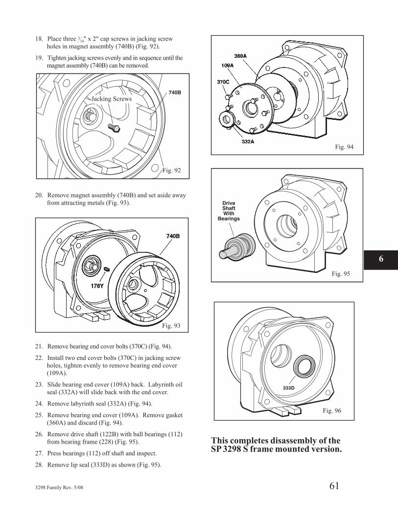
18. Place three 516" x 2" cap screws in jacking screw
holes in magnet assembly (740B) (Fig. 92).
19. Tighten jacking screws evenly and in sequence until the
magnet assembly (740B) can be removed.
20. Remove magnet assembly (740B) and set aside away
from attracting metals (Fig. 93).
21. Remove bearing end cover bolts (370C) (Fig. 94).
22. Install two end cover bolts (370C) in jacking screw
holes, tighten evenly to remove bearing end cover
(109A).
23. Slide bearing end cover (109A) back. Labyrinth oil
seal (332A) will slide back with the end cover.
24. Remove labyrinth seal (332A) (Fig. 94).
25. Remove bearing end cover (109A). Remove gasket
(360A) and discard (Fig. 94).
26. Remove drive shaft (122B) with ball bearings (112)
from bearing frame (228) (Fig. 95).
27. Press bearings (112) off shaft and inspect.
28. Remove lip seal (333D) as shown (Fig. 95).
This completes disassembly of theSP 3298 S frame mounted version.
3298 Family Rev. 5/08 61
6
Fig. 92
Jacking Screws
Fig. 93
Fig. 94
Fig. 95
Fig. 96
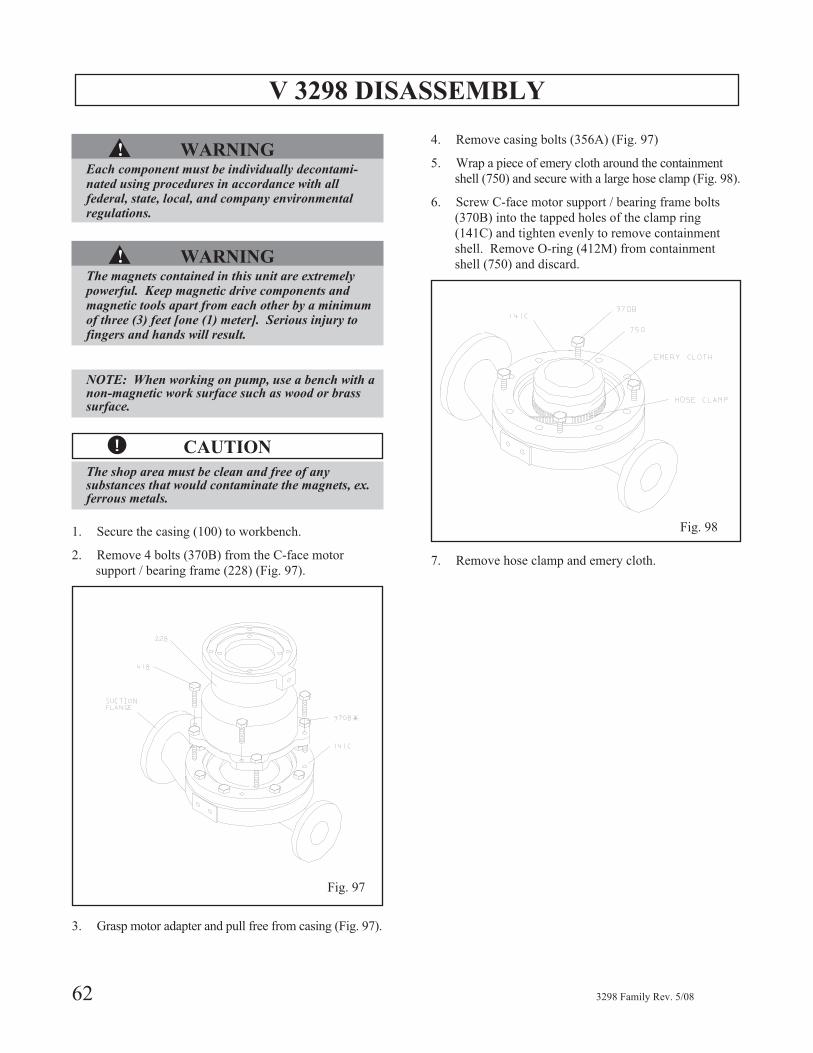
V 3298 DISASSEMBLY
▲! WARNINGEach component must be individually decontami-nated using procedures in accordance with allfederal, state, local, and company environmentalregulations.
▲! WARNINGThe magnets contained in this unit are extremelypowerful. Keep magnetic drive components andmagnetic tools apart from each other by a minimumof three (3) feet [one (1) meter]. Serious injury tofingers and hands will result.
NOTE: When working on pump, use a bench with anon-magnetic work surface such as wood or brasssurface.
� CAUTION
The shop area must be clean and free of anysubstances that would contaminate the magnets, ex.ferrous metals.
1. Secure the casing (100) to workbench.
2. Remove 4 bolts (370B) from the C-face motor
support / bearing frame (228) (Fig. 97).
3. Grasp motor adapter and pull free from casing (Fig. 97).
4. Remove casing bolts (356A) (Fig. 97)
5. Wrap a piece of emery cloth around the containment
shell (750) and secure with a large hose clamp (Fig. 98).
6. Screw C-face motor support / bearing frame bolts
(370B) into the tapped holes of the clamp ring
(141C) and tighten evenly to remove containment
shell. Remove O-ring (412M) from containment
shell (750) and discard.
7. Remove hose clamp and emery cloth.
62 3298 Family Rev. 5/08
Fig. 97
Fig. 98
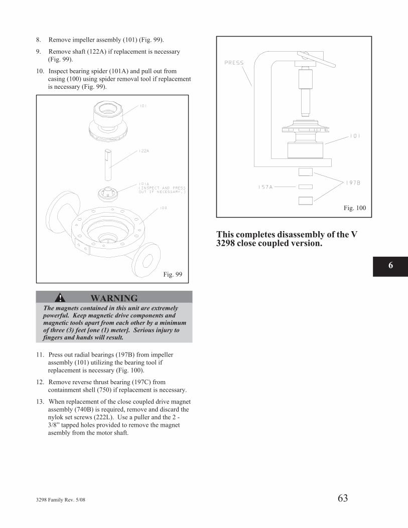
8. Remove impeller assembly (101) (Fig. 99).
9. Remove shaft (122A) if replacement is necessary
(Fig. 99).
10. Inspect bearing spider (101A) and pull out from
casing (100) using spider removal tool if replacement
is necessary (Fig. 99).
▲! WARNINGThe magnets contained in this unit are extremelypowerful. Keep magnetic drive components andmagnetic tools apart from each other by a minimumof three (3) feet [one (1) meter]. Serious injury tofingers and hands will result.
11. Press out radial bearings (197B) from impeller
assembly (101) utilizing the bearing tool if
replacement is necessary (Fig. 100).
12. Remove reverse thrust bearing (197C) from
containment shell (750) if replacement is necessary.
13. When replacement of the close coupled drive magnet
assembly (740B) is required, remove and discard the
nylok set screws (222L). Use a puller and the 2 -
3/8” tapped holes provided to remove the magnet
asembly from the motor shaft.
This completes disassembly of the V3298 close coupled version.
3298 Family Rev. 5/08 63
6Fig. 99
Fig. 100
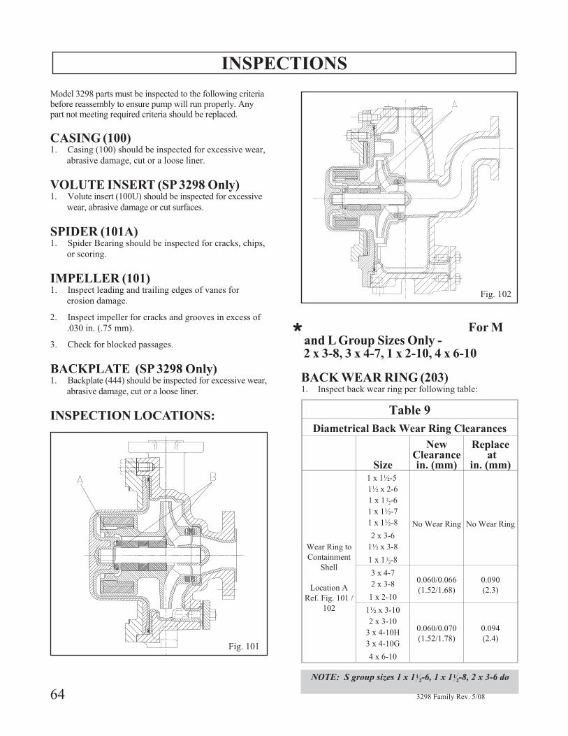
INSPECTIONS
Model 3298 parts must be inspected to the following criteriabefore reassembly to ensure pump will run properly. Anypart not meeting required criteria should be replaced.
CASING (100)1. Casing (100) should be inspected for excessive wear,
abrasive damage, cut or a loose liner.
VOLUTE INSERT (SP 3298 Only)1. Volute insert (100U) should be inspected for excessive
wear, abrasive damage or cut surfaces.
SPIDER (101A)1. Spider Bearing should be inspected for cracks, chips,
or scoring.
IMPELLER (101)1. Inspect leading and trailing edges of vanes for
erosion damage.
2. Inspect impeller for cracks and grooves in excess of
.030 in. (.75 mm).
3. Check for blocked passages.
BACKPLATE (SP 3298 Only)1. Backplate (444) should be inspected for excessive wear,
abrasive damage, cut or a loose liner.
INSPECTION LOCATIONS:
* For Mand L Group Sizes Only -2 x 3-8, 3 x 4-7, 1 x 2-10, 4 x 6-10
BACK WEAR RING (203)1. Inspect back wear ring per following table:
Table 9
Diametrical Back Wear Ring Clearances
Size
NewClearancein. (mm)
Replaceat
in. (mm)
Wear Ring to
Containment
Shell
Location A
Ref. Fig. 101 /
102
1 x 1½-5
1½ x 2-6
1 x 1 12-6
1 x 1½-7
1 x 1½-8 No Wear Ring No Wear Ring
2 x 3-6
1½ x 3-8
1 x 1 12-8
3 x 4-7
2 x 3-80.060/0.066
(1.52/1.68)
0.090
(2.3)1 x 2-10
1½ x 3-10
2 x 3-10
3 x 4-10H
3 x 4-10G
0.060/0.070
(1.52/1.78)
0.094
(2.4)
4 x 6-10
NOTE: S group sizes 1 x 112-6, 1 x 11
2-8, 2 x 3-6 do
64 3298 Family Rev. 5/08
Fig. 102
Fig. 101
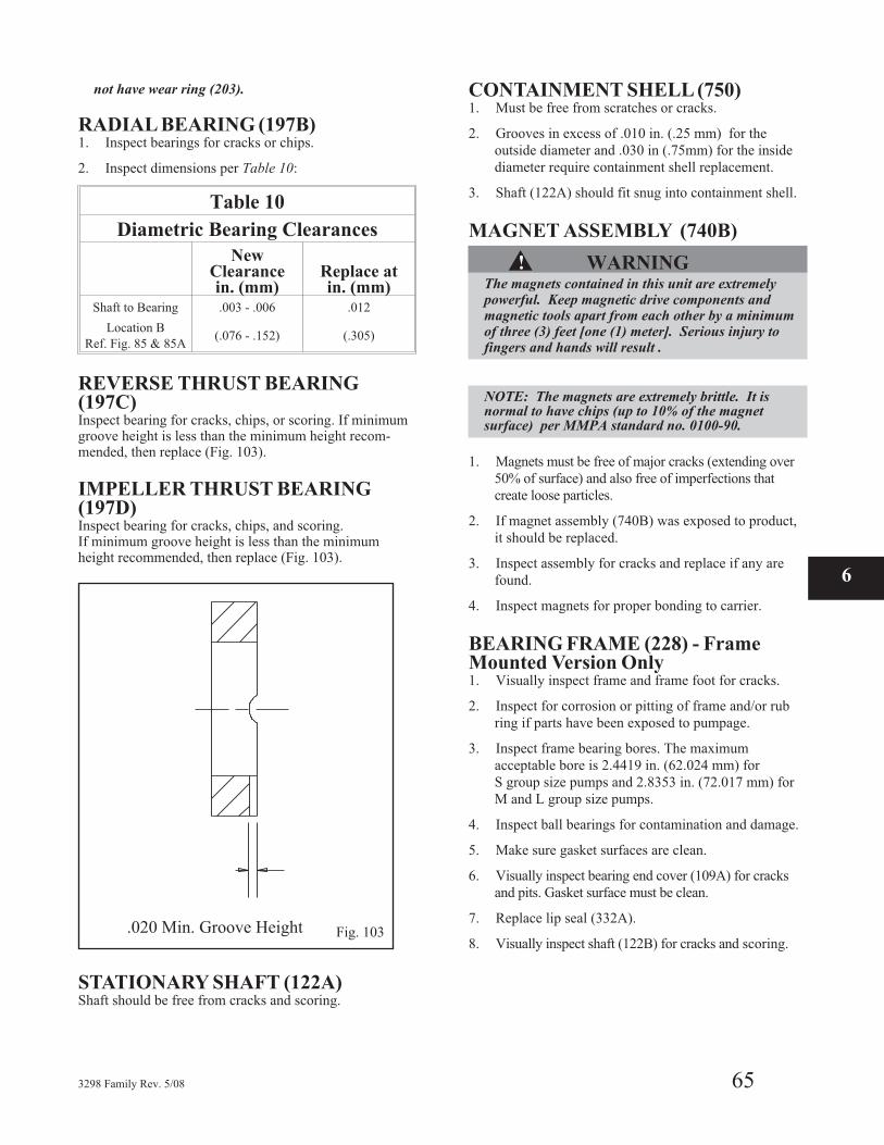
not have wear ring (203).
RADIAL BEARING (197B)1. Inspect bearings for cracks or chips.
2. Inspect dimensions per Table 10:
Table 10
Diametric Bearing Clearances
NewClearancein. (mm)
Replace atin. (mm)
Shaft to Bearing .003 - .006 .012
Location B
Ref. Fig. 85 & 85A(.076 - .152) (.305)
REVERSE THRUST BEARING(197C)Inspect bearing for cracks, chips, or scoring. If minimumgroove height is less than the minimum height recom-mended, then replace (Fig. 103).
IMPELLER THRUST BEARING(197D)Inspect bearing for cracks, chips, and scoring.If minimum groove height is less than the minimumheight recommended, then replace (Fig. 103).
STATIONARY SHAFT (122A)Shaft should be free from cracks and scoring.
CONTAINMENT SHELL (750)1. Must be free from scratches or cracks.
2. Grooves in excess of .010 in. (.25 mm) for the
outside diameter and .030 in (.75mm) for the inside
diameter require containment shell replacement.
3. Shaft (122A) should fit snug into containment shell.
MAGNET ASSEMBLY (740B)
▲! WARNINGThe magnets contained in this unit are extremelypowerful. Keep magnetic drive components andmagnetic tools apart from each other by a minimumof three (3) feet [one (1) meter]. Serious injury tofingers and hands will result .
NOTE: The magnets are extremely brittle. It isnormal to have chips (up to 10% of the magnetsurface) per MMPA standard no. 0100-90.
1. Magnets must be free of major cracks (extending over
50% of surface) and also free of imperfections that
create loose particles.
2. If magnet assembly (740B) was exposed to product,
it should be replaced.
3. Inspect assembly for cracks and replace if any are
found.
4. Inspect magnets for proper bonding to carrier.
BEARING FRAME (228) - FrameMounted Version Only1. Visually inspect frame and frame foot for cracks.
2. Inspect for corrosion or pitting of frame and/or rub
ring if parts have been exposed to pumpage.
3. Inspect frame bearing bores. The maximum
acceptable bore is 2.4419 in. (62.024 mm) for
S group size pumps and 2.8353 in. (72.017 mm) for
M and L group size pumps.
4. Inspect ball bearings for contamination and damage.
5. Make sure gasket surfaces are clean.
6. Visually inspect bearing end cover (109A) for cracks
and pits. Gasket surface must be clean.
7. Replace lip seal (332A).
8. Visually inspect shaft (122B) for cracks and scoring.
3298 Family Rev. 5/08 65
6
Fig. 103.020 Min. Groove Height
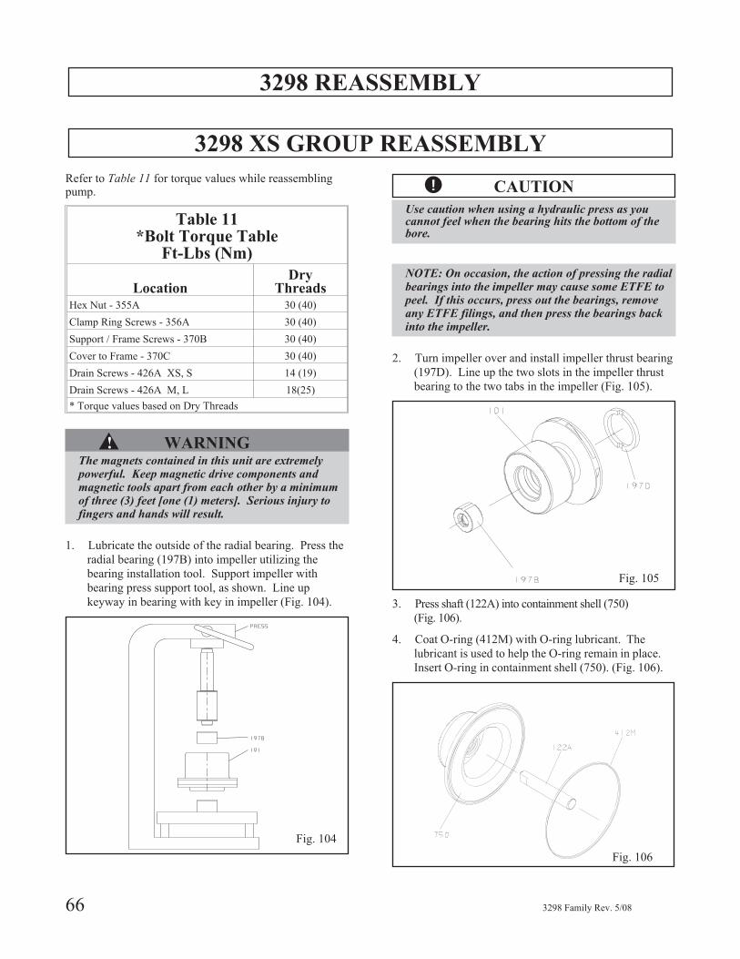
3298 REASSEMBLY
3298 XS GROUP REASSEMBLY
Refer to Table 11 for torque values while reassemblingpump.
Table 11*Bolt Torque Table
Ft-Lbs (Nm)
LocationDry
ThreadsHex Nut - 355A 30 (40)
Clamp Ring Screws - 356A 30 (40)
Support / Frame Screws - 370B 30 (40)
Cover to Frame - 370C 30 (40)
Drain Screws - 426A XS, S 14 (19)
Drain Screws - 426A M, L 18(25)
* Torque values based on Dry Threads
▲! WARNINGThe magnets contained in this unit are extremelypowerful. Keep magnetic drive components andmagnetic tools apart from each other by a minimumof three (3) feet [one (1) meters]. Serious injury tofingers and hands will result.
1. Lubricate the outside of the radial bearing. Press the
radial bearing (197B) into impeller utilizing the
bearing installation tool. Support impeller with
bearing press support tool, as shown. Line up
keyway in bearing with key in impeller (Fig. 104).
� CAUTION
Use caution when using a hydraulic press as youcannot feel when the bearing hits the bottom of thebore.
NOTE: On occasion, the action of pressing the radialbearings into the impeller may cause some ETFE topeel. If this occurs, press out the bearings, removeany ETFE filings, and then press the bearings backinto the impeller.
2. Turn impeller over and install impeller thrust bearing
(197D). Line up the two slots in the impeller thrust
bearing to the two tabs in the impeller (Fig. 105).
3. Press shaft (122A) into containment shell (750)
(Fig. 106).
4. Coat O-ring (412M) with O-ring lubricant. The
lubricant is used to help the O-ring remain in place.
Insert O-ring in containment shell (750). (Fig. 106).
66 3298 Family Rev. 5/08
Fig. 104
Fig. 105
Fig. 106

5. Slide impeller assembly (101) onto shaft (Fig. 107).
6. Press spider (101A) into casing (100) with spider
tool (Fig. 108).
7. Check rotary assembly total travel. See Fig. 109 for
the appropriate measurements needed. For the XS
pump, total travel is A - B and should be 0.026 -
0.083 in. (0.66-2.11 mm).
8. Install containment shell / impeller assembly into
casing (100). Use care that the O-ring (412M)
remains in place.
▲! WARNINGThe magnets contained in this unit are extremelypowerful. Serious injury to fingers and hands willresult if care is not taken.
9. Install clamp ring (141C) to casing (100) with 6 hex
cap screws (356A) (Fig. 109).
10. Set partially built assembly aside well away from
attracting metals.
3298 Family Rev. 5/08 67
6
Fig. 107
Fig. 108
Fig. 109
Fig. 110
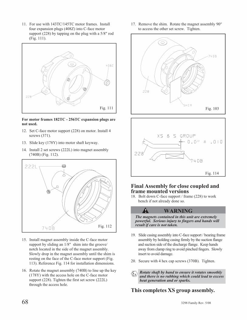
11. For use with 143TC/145TC motor frames. Install
four expansion plugs (408Z) into C-face motor
support (228) by tapping on the plug with a 5/8" rod
(Fig. 111).
For motor frames 182TC - 256TC expansion plugs are
not used.
12. Set C-face motor support (228) on motor. Install 4
screws (371).
13. Slide key (178Y) into motor shaft keyway.
14. Install 2 set screws (222L) into magnet assembly
(740B) (Fig. 112).
15. Install magnet assembly inside the C-face motor
support by sliding an 1/8" shim into the groove/
notch located in the side of the magnet assembly.
Slowly drop in the magnet assembly until the shim is
resting on the face of the C-face motor support (Fig.
113). Reference Fig. 114 for installation dimensions.
16. Rotate the magnet assembly (740B) to line up the key
(178Y) with the access hole on the C-face motor
support (228). Tighten the first set screw (222L)
through the access hole.
17. Remove the shim. Rotate the magnet assembly 90°
to access the other set screw. Tighten.
Final Assembly for close coupled andframe mounted versions18. Bolt down C-face support / frame (228) to work
bench if not already done so.
▲! WARNINGThe magnets contained in this unit are extremelypowerful. Serious injury to fingers and hands willresult if care is not taken.
19. Slide casing assembly into C-face support / bearing frame
assembly by holding casing firmly by the suction flange
and suction side of the discharge flange. Keep hands
away from clamp ring to avoid pinched fingers. Slowly
insert to avoid damage.
20. Secure with 4 hex cap screws (370B). Tighten.
� Rotate shaft by hand to ensure it rotates smoothlyand there is no rubbing which could lead to excessheat generation and or sparks.
This completes XS group assembly.
68 3298 Family Rev. 5/08
Fig. 111
Fig. 112
Fig. 113
Fig. 114
Fig. 103
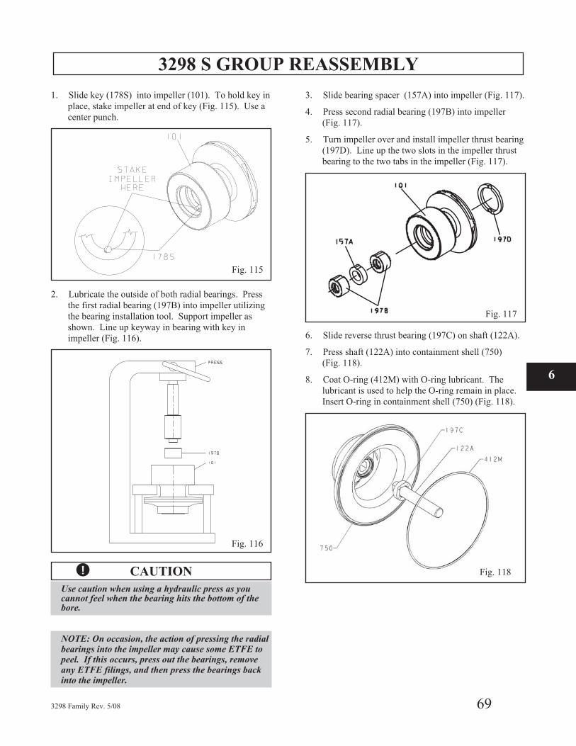
3298 S GROUP REASSEMBLY
1. Slide key (178S) into impeller (101). To hold key in
place, stake impeller at end of key (Fig. 115). Use a
center punch.
2. Lubricate the outside of both radial bearings. Press
the first radial bearing (197B) into impeller utilizing
the bearing installation tool. Support impeller as
shown. Line up keyway in bearing with key in
impeller (Fig. 116).
� CAUTION
Use caution when using a hydraulic press as youcannot feel when the bearing hits the bottom of thebore.
NOTE: On occasion, the action of pressing the radialbearings into the impeller may cause some ETFE topeel. If this occurs, press out the bearings, removeany ETFE filings, and then press the bearings backinto the impeller.
3. Slide bearing spacer (157A) into impeller (Fig. 117).
4. Press second radial bearing (197B) into impeller
(Fig. 117).
5. Turn impeller over and install impeller thrust bearing
(197D). Line up the two slots in the impeller thrust
bearing to the two tabs in the impeller (Fig. 117).
6. Slide reverse thrust bearing (197C) on shaft (122A).
7. Press shaft (122A) into containment shell (750)
(Fig. 118).
8. Coat O-ring (412M) with O-ring lubricant. The
lubricant is used to help the O-ring remain in place.
Insert O-ring in containment shell (750) (Fig. 118).
3298 Family Rev. 5/08 69
6
Fig. 115
Fig. 116
Fig. 117
Fig. 118
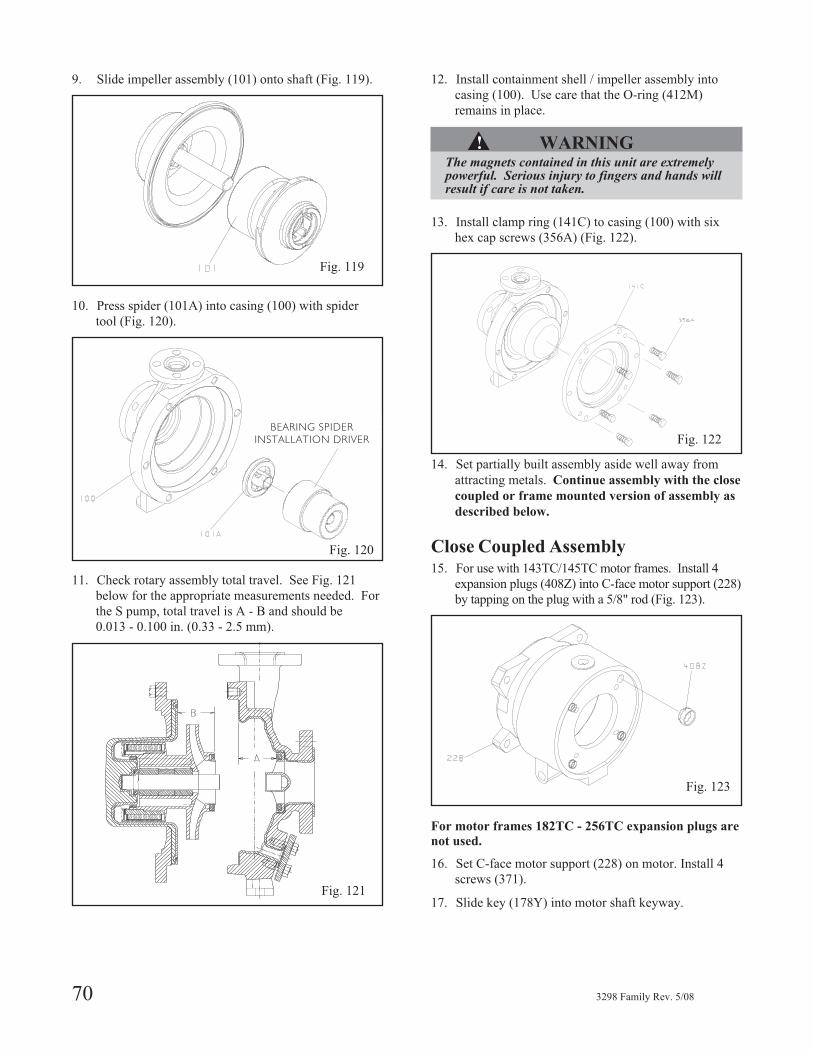
9. Slide impeller assembly (101) onto shaft (Fig. 119).
10. Press spider (101A) into casing (100) with spider
tool (Fig. 120).
11. Check rotary assembly total travel. See Fig. 121
below for the appropriate measurements needed. For
the S pump, total travel is A - B and should be
0.013 - 0.100 in. (0.33 - 2.5 mm).
12. Install containment shell / impeller assembly into
casing (100). Use care that the O-ring (412M)
remains in place.
▲! WARNINGThe magnets contained in this unit are extremelypowerful. Serious injury to fingers and hands willresult if care is not taken.
13. Install clamp ring (141C) to casing (100) with six
hex cap screws (356A) (Fig. 122).
14. Set partially built assembly aside well away from
attracting metals. Continue assembly with the close
coupled or frame mounted version of assembly as
described below.
Close Coupled Assembly15. For use with 143TC/145TC motor frames. Install 4
expansion plugs (408Z) into C-face motor support (228)
by tapping on the plug with a 5/8" rod (Fig. 123).
For motor frames 182TC - 256TC expansion plugs are
not used.
16. Set C-face motor support (228) on motor. Install 4
screws (371).
17. Slide key (178Y) into motor shaft keyway.
70 3298 Family Rev. 5/08
Fig. 119
Fig. 120
BEARING SPIDER
INSTALLATION DRIVER
Fig. 121
Fig. 122
Fig. 123
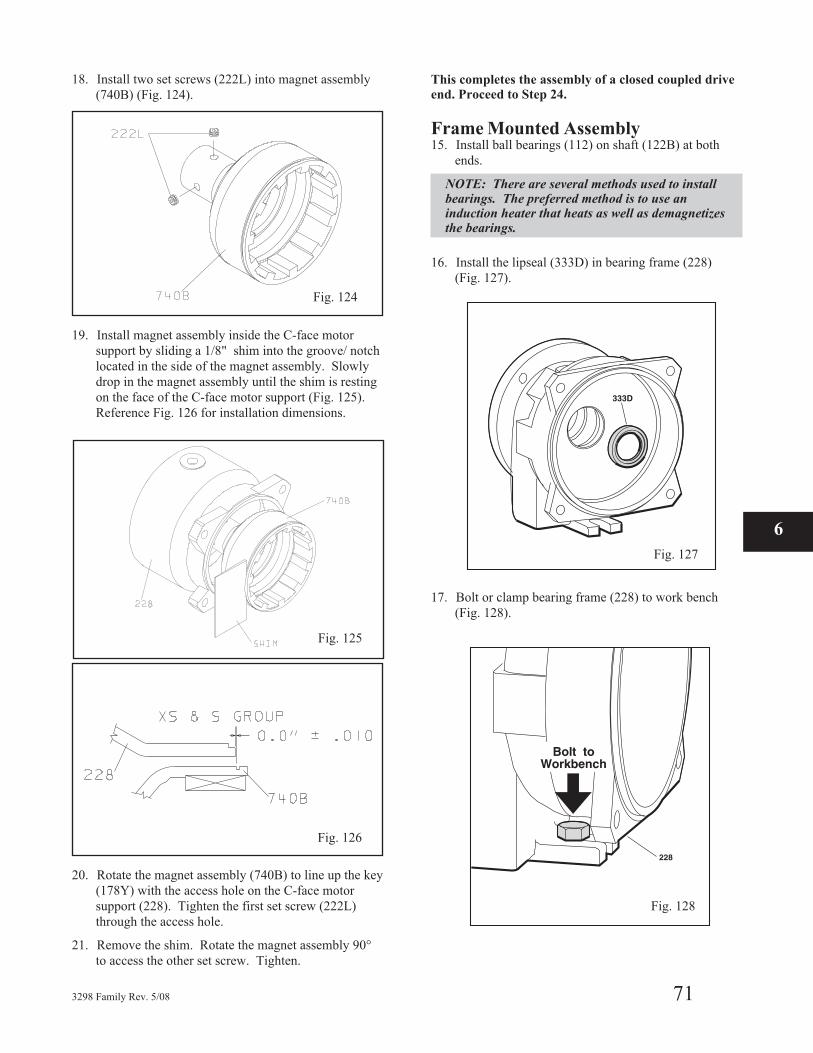
18. Install two set screws (222L) into magnet assembly
(740B) (Fig. 124).
19. Install magnet assembly inside the C-face motor
support by sliding a 1/8" shim into the groove/ notch
located in the side of the magnet assembly. Slowly
drop in the magnet assembly until the shim is resting
on the face of the C-face motor support (Fig. 125).
Reference Fig. 126 for installation dimensions.
20. Rotate the magnet assembly (740B) to line up the key
(178Y) with the access hole on the C-face motor
support (228). Tighten the first set screw (222L)
through the access hole.
21. Remove the shim. Rotate the magnet assembly 90°
to access the other set screw. Tighten.
This completes the assembly of a closed coupled drive
end. Proceed to Step 24.
Frame Mounted Assembly15. Install ball bearings (112) on shaft (122B) at both
ends.
NOTE: There are several methods used to installbearings. The preferred method is to use aninduction heater that heats as well as demagnetizesthe bearings.
16. Install the lipseal (333D) in bearing frame (228)
(Fig. 127).
17. Bolt or clamp bearing frame (228) to work bench
(Fig. 128).
3298 Family Rev. 5/08 71
6
Fig. 124
Fig. 126
Fig. 127
Fig. 125
Fig. 128
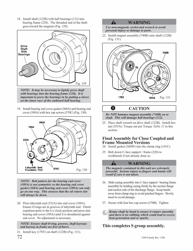
18. Install shaft (122B) with ball bearings (112) into
bearing frame (228). The threaded end of the shaft
goes toward the magnets (Fig. 129).
NOTE: It may be necessary to lightly press shaftwith bearings into the bearing frame (228). It isimportant to press the bearings in by putting a sleeveon the inner race of the outboard ball bearing.
19. Install bearing end cover gasket (360A) and bearing end
cover (109A) with hex cap screws (370C) (Fig. 130).
NOTE: Bolt pattern for the bearing end cover(109A) is not symmetric so the bearing end covergasket (360A) and bearing end cover (109A) can onlygo on one way. This ensures that the oil return slotwill always be down.
20. Press labyrinth seal (332A) into end cover (109A).
Ensure O-rings are in grooves of labyrinth seal. Orient
expulsion ports to the 6 o’clock position and press into
bearing end cover (109A) until it is shouldered against
end cover. No adjustment is necessary.
NOTE: Ensure shaft O-ring, grooves, shaft keywaysand keyway in frame are free of burrs.
21. Install key (178Y) on shaft (122B) (Fig. 131).
▲! WARNINGUse non-magnetic socket and wrench to avoidpersonal injury or damage to parts.
22. Install magnet assembly (740B) onto shaft (122B)
(Fig. 131).
� CAUTION
Do NOT hammer magnet assembly (740B) on toshaft. This will damage ball bearings (112).
23. Place shaft wrench on drive shaft (122B). Install hex
nut (355A). Torque nut per Torque Table 11 in this
section.
Final Assembly for Close Coupled andFrame Mounted Versions24. Install gasket (360W) into the clamp ring (141C).
25. Bolt down C-face support / frame (228) to
workbench if not already done so.
▲! WARNINGThe magnets contained in this unit are extremelypowerful. Serious injury to fingers and hands willresult if care is not taken.
26. Slide casing assembly into C-face support / bearing frame
assembly by holding casing firmly by the suction flange
and suction side of the discharge flange. Keep hands
away from clamp ring to avoid pinched fingers. Slowly
insert to avoid damage.
27. Secure with four hex cap screws (370B). Tighten.
� Rotate shaft by hand to ensure it rotates smoothlyand there is no rubbing which could lead to excessheat generation and or sparks.
This completes S group assembly.
72 3298 Family Rev. 5/08
Fig. 129
Fig. 130
Fig. 131
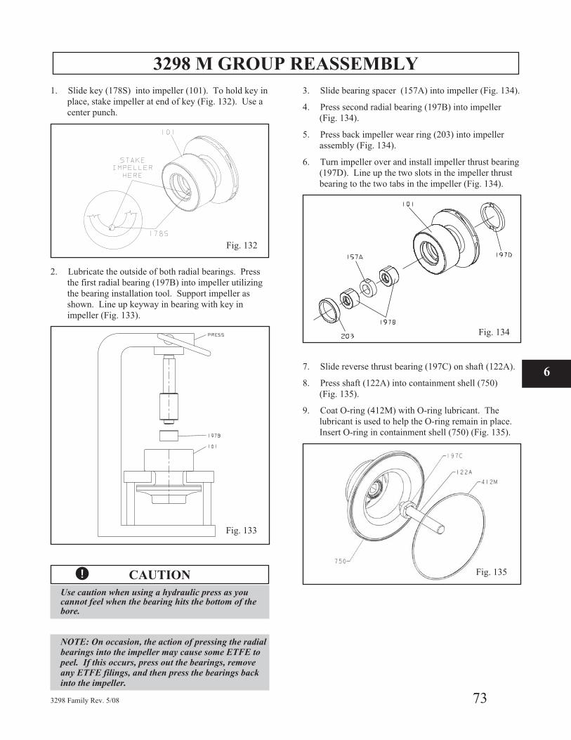
3298 M GROUP REASSEMBLY
1. Slide key (178S) into impeller (101). To hold key in
place, stake impeller at end of key (Fig. 132). Use a
center punch.
2. Lubricate the outside of both radial bearings. Press
the first radial bearing (197B) into impeller utilizing
the bearing installation tool. Support impeller as
shown. Line up keyway in bearing with key in
impeller (Fig. 133).
� CAUTION
Use caution when using a hydraulic press as youcannot feel when the bearing hits the bottom of thebore.
NOTE: On occasion, the action of pressing the radialbearings into the impeller may cause some ETFE topeel. If this occurs, press out the bearings, removeany ETFE filings, and then press the bearings backinto the impeller.
3. Slide bearing spacer (157A) into impeller (Fig. 134).
4. Press second radial bearing (197B) into impeller
(Fig. 134).
5. Press back impeller wear ring (203) into impeller
assembly (Fig. 134).
6. Turn impeller over and install impeller thrust bearing
(197D). Line up the two slots in the impeller thrust
bearing to the two tabs in the impeller (Fig. 134).
7. Slide reverse thrust bearing (197C) on shaft (122A).
8. Press shaft (122A) into containment shell (750)
(Fig. 135).
9. Coat O-ring (412M) with O-ring lubricant. The
lubricant is used to help the O-ring remain in place.
Insert O-ring in containment shell (750) (Fig. 135).
3298 Family Rev. 5/08 73
6
Fig. 132
Fig. 133
Fig. 134
Fig. 135
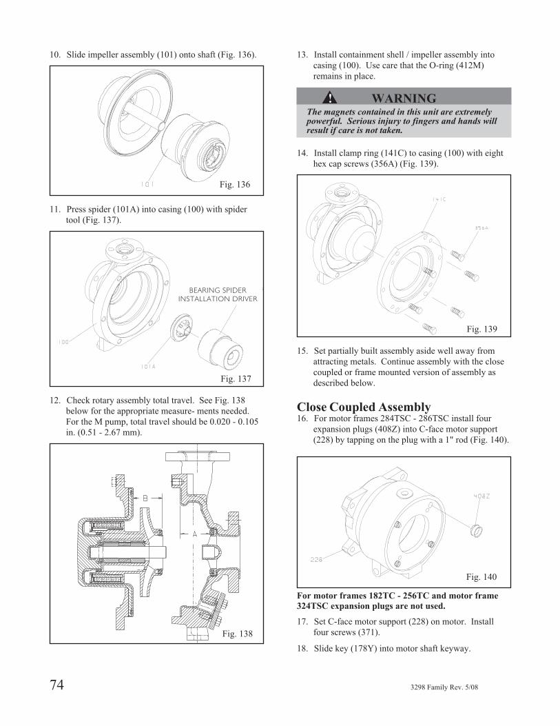
10. Slide impeller assembly (101) onto shaft (Fig. 136).
11. Press spider (101A) into casing (100) with spider
tool (Fig. 137).
12. Check rotary assembly total travel. See Fig. 138
below for the appropriate measure- ments needed.
For the M pump, total travel should be 0.020 - 0.105
in. (0.51 - 2.67 mm).
13. Install containment shell / impeller assembly into
casing (100). Use care that the O-ring (412M)
remains in place.
▲! WARNINGThe magnets contained in this unit are extremelypowerful. Serious injury to fingers and hands willresult if care is not taken.
14. Install clamp ring (141C) to casing (100) with eight
hex cap screws (356A) (Fig. 139).
15. Set partially built assembly aside well away from
attracting metals. Continue assembly with the close
coupled or frame mounted version of assembly as
described below.
Close Coupled Assembly16. For motor frames 284TSC - 286TSC install four
expansion plugs (408Z) into C-face motor support
(228) by tapping on the plug with a 1" rod (Fig. 140).
For motor frames 182TC - 256TC and motor frame
324TSC expansion plugs are not used.
17. Set C-face motor support (228) on motor. Install
four screws (371).
18. Slide key (178Y) into motor shaft keyway.
74 3298 Family Rev. 5/08
Fig. 136
Fig. 137
BEARING SPIDER
INSTALLATION DRIVER
Fig. 138
Fig. 139
Fig. 140
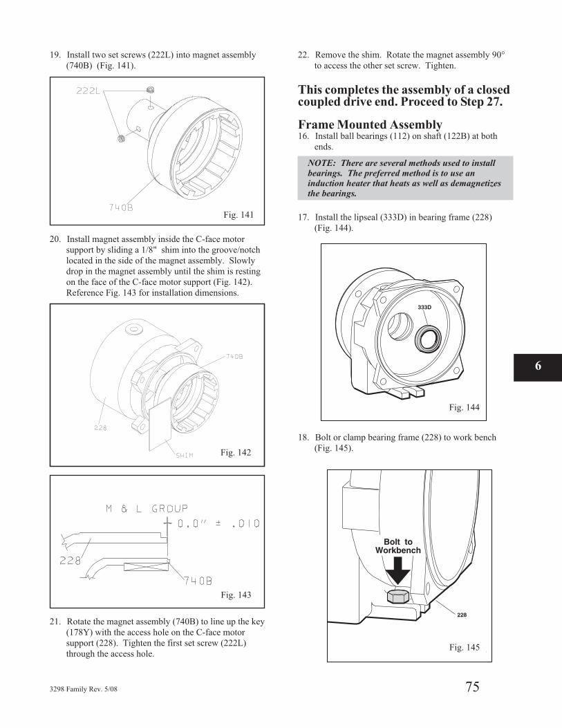
19. Install two set screws (222L) into magnet assembly
(740B) (Fig. 141).
20. Install magnet assembly inside the C-face motor
support by sliding a 1/8" shim into the groove/notch
located in the side of the magnet assembly. Slowly
drop in the magnet assembly until the shim is resting
on the face of the C-face motor support (Fig. 142).
Reference Fig. 143 for installation dimensions.
21. Rotate the magnet assembly (740B) to line up the key
(178Y) with the access hole on the C-face motor
support (228). Tighten the first set screw (222L)
through the access hole.
22. Remove the shim. Rotate the magnet assembly 90°
to access the other set screw. Tighten.
This completes the assembly of a closedcoupled drive end. Proceed to Step 27.
Frame Mounted Assembly16. Install ball bearings (112) on shaft (122B) at both
ends.
NOTE: There are several methods used to installbearings. The preferred method is to use aninduction heater that heats as well as demagnetizesthe bearings.
17. Install the lipseal (333D) in bearing frame (228)
(Fig. 144).
18. Bolt or clamp bearing frame (228) to work bench
(Fig. 145).
3298 Family Rev. 5/08 75
6
Fig. 141
Fig. 142
Fig. 143
Fig. 144
Fig. 145
Fig. 142
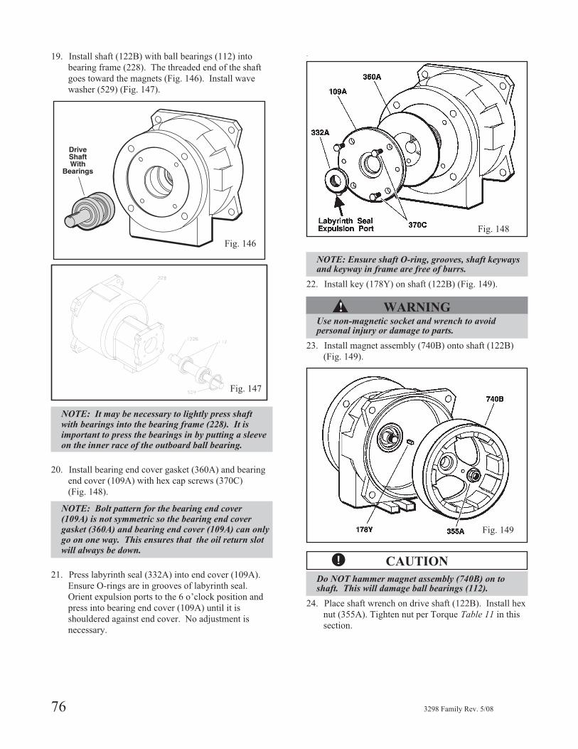
19. Install shaft (122B) with ball bearings (112) into
bearing frame (228). The threaded end of the shaft
goes toward the magnets (Fig. 146). Install wave
washer (529) (Fig. 147).
NOTE: It may be necessary to lightly press shaftwith bearings into the bearing frame (228). It isimportant to press the bearings in by putting a sleeveon the inner race of the outboard ball bearing.
20. Install bearing end cover gasket (360A) and bearing
end cover (109A) with hex cap screws (370C)
(Fig. 148).
NOTE: Bolt pattern for the bearing end cover(109A) is not symmetric so the bearing end covergasket (360A) and bearing end cover (109A) can onlygo on one way. This ensures that the oil return slotwill always be down.
21. Press labyrinth seal (332A) into end cover (109A).
Ensure O-rings are in grooves of labyrinth seal.
Orient expulsion ports to the 6 o’clock position and
press into bearing end cover (109A) until it is
shouldered against end cover. No adjustment is
necessary.
.
NOTE: Ensure shaft O-ring, grooves, shaft keywaysand keyway in frame are free of burrs.
22. Install key (178Y) on shaft (122B) (Fig. 149).
▲! WARNINGUse non-magnetic socket and wrench to avoidpersonal injury or damage to parts.
23. Install magnet assembly (740B) onto shaft (122B)
(Fig. 149).
� CAUTION
Do NOT hammer magnet assembly (740B) on toshaft. This will damage ball bearings (112).
24. Place shaft wrench on drive shaft (122B). Install hex
nut (355A). Tighten nut per Torque Table 11 in this
section.
76 3298 Family Rev. 5/08
Fig. 146
Fig. 147
Fig. 148
Fig. 149
Fig. 147
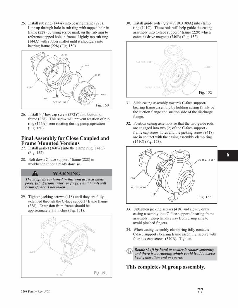
25. Install rub ring (144A) into bearing frame (228).
Line up through hole in rub ring with tapped hole in
frame (228) by using scribe mark on the rub ring to
reference tapped hole in frame. Lightly tap rub ring
(144A) with rubber mallet until it shoulders into
bearing frame (228) (Fig. 150).
26. Install 516" hex cap screw (372Y) into bottom of
frame (228). This screw will prevent rotation of rub
ring (144A) from rotating during pump operation
(Fig. 150).
Final Assembly for Close Coupled andFrame Mounted Versions27. Install gasket (360W) into the clamp ring (141C)
(Fig. 152).
28. Bolt down C-face support / frame (228) to
workbench if not already done so.
▲! WARNINGThe magnets contained in this unit are extremelypowerful. Serious injury to fingers and hands willresult if care is not taken.
29. Tighten jacking screws (418) until they are fully
extended through the C-face support / frame flange
(228). Extension from frame should be
approximately 3.5 inches (Fig. 151).
30. Install guide rods (Qty = 2, B03189A) into clamp
ring (141C). These rods will help guide the casing
assembly into C-face support / frame (228) which
contains drive magnets (740B) (Fig. 152).
31. Slide casing assembly towards C-face support/
bearing frame assembly by holding casing firmly by
the suction flange and suction side of the discharge
flange.
32. Position casing assembly so that the two guide rods
are engaged into two (2) of the C-face support /
frame cap screw holes and the jacking screws (418)
are in contact with the casing assembly clamp ring
(141C) (Fig. 153).
33. Untighten jacking screws (418) and slowly draw
casing assembly into C-face support / bearing frame
assembly. Keep hands away from clamp ring to
avoid pinched fingers.
34. When casing assembly clamp ring fully contacts
C-face support / bearing frame assembly, secure with
four hex cap screws (370B). Tighten.
� Rotate shaft by hand to ensure it rotates smoothlyand there is no rubbing which could lead to excessheat generation and or sparks.
This completes M group assembly.
3298 Family Rev. 5/08 77
6
Fig. 150
Fig. 151
Fig. 152
Fig. 153
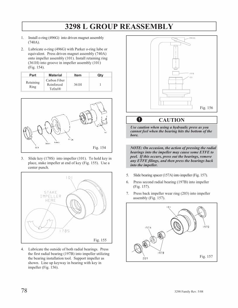
3298 L GROUP REASSEMBLY
1. Install o-ring (496G) into driven magnet assembly
(740A).
2. Lubricate o-ring (496G) with Parker o-ring lube or
equivalent. Press driven magnet assembly (740A)
onto impeller assembly (101). Install retaining ring
(361H) into groove in impeller assembly (101)
(Fig. 154).
Part Material Item Qty
Retaining
Ring
Carbon Fiber
Reinforced
Tefzel®
361H 1
3. Slide key (178S) into impeller (101). To hold key in
place, stake impeller at end of key (Fig. 155). Use a
center punch.
4. Lubricate the outside of both radial bearings. Press
the first radial bearing (197B) into impeller utilizing
the bearing installation tool. Support impeller as
shown. Line up keyway in bearing with key in
impeller (Fig. 156).
� CAUTION
Use caution when using a hydraulic press as youcannot feel when the bearing hits the bottom of thebore.
NOTE: On occasion, the action of pressing the radialbearings into the impeller may cause some ETFE topeel. If this occurs, press out the bearings, removeany ETFE filings, and then press the bearings backinto the impeller.
5. Slide bearing spacer (157A) into impeller (Fig. 157).
6. Press second radial bearing (197B) into impeller
(Fig. 157).
7. Press back impeller wear ring (203) into impeller
assembly (Fig. 157).
78 3298 Family Rev. 5/08
Fig. 154
Fig. 155
Fig. 156
Fig. 157
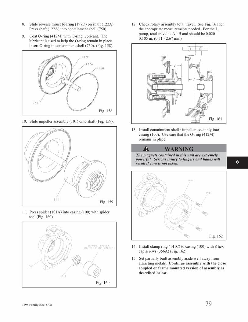
8. Slide reverse thrust bearing (197D) on shaft (122A).
Press shaft (122A) into containment shell (750).
9. Coat O-ring (412M) with O-ring lubricant. The
lubricant is used to help the O-ring remain in place.
Insert O-ring in containment shell (750). (Fig. 158).
10. Slide impeller assembly (101) onto shaft (Fig. 159).
11. Press spider (101A) into casing (100) with spider
tool (Fig. 160).
12. Check rotary assembly total travel. See Fig. 161 for
the appropriate measurements needed. For the L
pump, total travel is A - B and should be 0.020 -
0.105 in. (0.51 - 2.67 mm)
13. Install containment shell / impeller assembly into
casing (100). Use care that the O-ring (412M)
remains in place.
▲! WARNINGThe magnets contained in this unit are extremelypowerful. Serious injury to fingers and hands willresult if care is not taken.
14. Install clamp ring (141C) to casing (100) with 8 hex
cap screws (356A) (Fig. 162).
15. Set partially built assembly aside well away from
attracting metals. Continue assembly with the close
coupled or frame mounted version of assembly as
described below.
3298 Family Rev. 5/08 79
6
Fig. 158
Fig. 159
Fig. 160
Fig. 161
Fig. 162
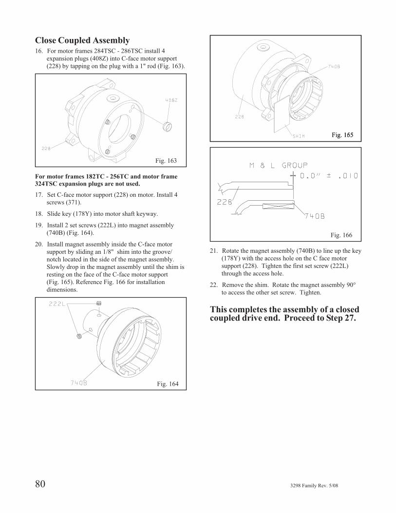
Close Coupled Assembly16. For motor frames 284TSC - 286TSC install 4
expansion plugs (408Z) into C-face motor support
(228) by tapping on the plug with a 1" rod (Fig. 163).
For motor frames 182TC - 256TC and motor frame
324TSC expansion plugs are not used.
17. Set C-face motor support (228) on motor. Install 4
screws (371).
18. Slide key (178Y) into motor shaft keyway.
19. Install 2 set screws (222L) into magnet assembly
(740B) (Fig. 164).
20. Install magnet assembly inside the C-face motor
support by sliding an 1/8" shim into the groove/
notch located in the side of the magnet assembly.
Slowly drop in the magnet assembly until the shim is
resting on the face of the C-face motor support
(Fig. 165). Reference Fig. 166 for installation
dimensions.
21. Rotate the magnet assembly (740B) to line up the key
(178Y) with the access hole on the C face motor
support (228). Tighten the first set screw (222L)
through the access hole.
22. Remove the shim. Rotate the magnet assembly 90°
to access the other set screw. Tighten.
This completes the assembly of a closedcoupled drive end. Proceed to Step 27.
80 3298 Family Rev. 5/08
Fig. 163
Fig. 164
Fig. 165
Fig. 166
Fig. 155
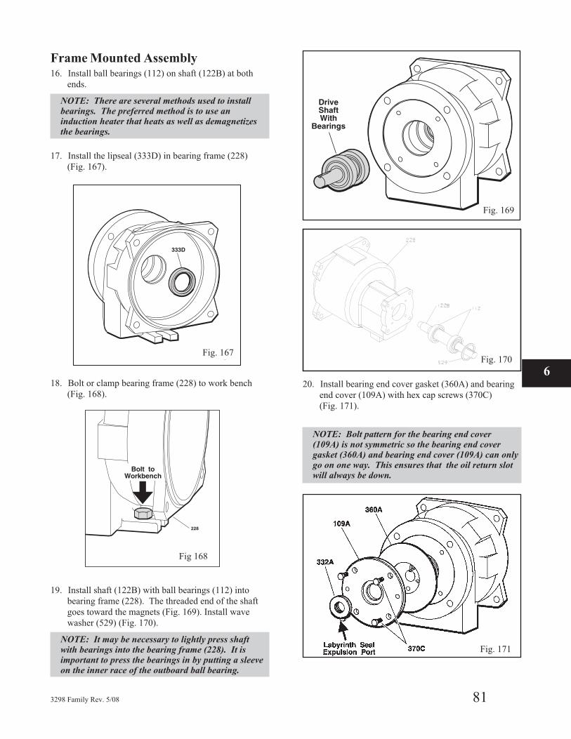
Frame Mounted Assembly16. Install ball bearings (112) on shaft (122B) at both
ends.
NOTE: There are several methods used to installbearings. The preferred method is to use aninduction heater that heats as well as demagnetizesthe bearings.
17. Install the lipseal (333D) in bearing frame (228)
(Fig. 167).
18. Bolt or clamp bearing frame (228) to work bench
(Fig. 168).
19. Install shaft (122B) with ball bearings (112) into
bearing frame (228). The threaded end of the shaft
goes toward the magnets (Fig. 169). Install wave
washer (529) (Fig. 170).
NOTE: It may be necessary to lightly press shaftwith bearings into the bearing frame (228). It isimportant to press the bearings in by putting a sleeveon the inner race of the outboard ball bearing.
20. Install bearing end cover gasket (360A) and bearing
end cover (109A) with hex cap screws (370C)
(Fig. 171).
NOTE: Bolt pattern for the bearing end cover(109A) is not symmetric so the bearing end covergasket (360A) and bearing end cover (109A) can onlygo on one way. This ensures that the oil return slotwill always be down.
3298 Family Rev. 5/08 81
6
Fig. 167
Fig 168
Fig. 169
Fig. 170
Fig. 171
Fig. 170
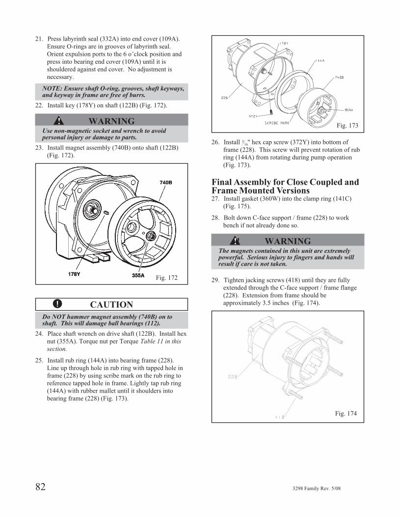
21. Press labyrinth seal (332A) into end cover (109A).
Ensure O-rings are in grooves of labyrinth seal.
Orient expulsion ports to the 6 o’clock position and
press into bearing end cover (109A) until it is
shouldered against end cover. No adjustment is
necessary.
NOTE: Ensure shaft O-ring, grooves, shaft keyways,and keyway in frame are free of burrs.
22. Install key (178Y) on shaft (122B) (Fig. 172).
▲! WARNINGUse non-magnetic socket and wrench to avoidpersonal injury or damage to parts.
23. Install magnet assembly (740B) onto shaft (122B)
(Fig. 172).
� CAUTION
Do NOT hammer magnet assembly (740B) on toshaft. This will damage ball bearings (112).
24. Place shaft wrench on drive shaft (122B). Install hex
nut (355A). Torque nut per Torque Table 11 in this
section.
25. Install rub ring (144A) into bearing frame (228).
Line up through hole in rub ring with tapped hole in
frame (228) by using scribe mark on the rub ring to
reference tapped hole in frame. Lightly tap rub ring
(144A) with rubber mallet until it shoulders into
bearing frame (228) (Fig. 173).
26. Install 516" hex cap screw (372Y) into bottom of
frame (228). This screw will prevent rotation of rub
ring (144A) from rotating during pump operation
(Fig. 173).
Final Assembly for Close Coupled andFrame Mounted Versions27. Install gasket (360W) into the clamp ring (141C)
(Fig. 175).
28. Bolt down C-face support / frame (228) to work
bench if not already done so.
▲!! WARNINGThe magnets contained in this unit are extremelypowerful. Serious injury to fingers and hands willresult if care is not taken.
29. Tighten jacking screws (418) until they are fully
extended through the C-face support / frame flange
(228). Extension from frame should be
approximately 3.5 inches (Fig. 174).
82 3298 Family Rev. 5/08
Fig. 172
Fig. 173
Fig. 174
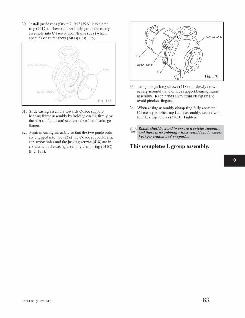
30. Install guide rods (Qty = 2, B03189A) into clamp
ring (141C). These rods will help guide the casing
assembly into C-face support/frame (228) which
contains drive magnets (740B) (Fig. 175).
31. Slide casing assembly towards C-face support/
bearing frame assembly by holding casing firmly by
the suction flange and suction side of the discharge
flange.
32. Position casing assembly so that the two guide rods
are engaged into two (2) of the C-face support/frame
cap screw holes and the jacking screws (418) are in
contact with the casing assembly clamp ring (141C)
(Fig. 176).
33. Untighten jacking screws (418) and slowly draw
casing assembly into C-face support/bearing frame
assembly. Keep hands away from clamp ring to
avoid pinched fingers.
34. When casing assembly clamp ring fully contacts
C-face support/bearing frame assembly, secure with
four hex cap screws (370B). Tighten.
� Rotate shaft by hand to ensure it rotates smoothlyand there is no rubbing which could lead to excessheat generation and or sparks.
This completes L group assembly.
3298 Family Rev. 5/08 83
6
Fig. 175
Fig. 176
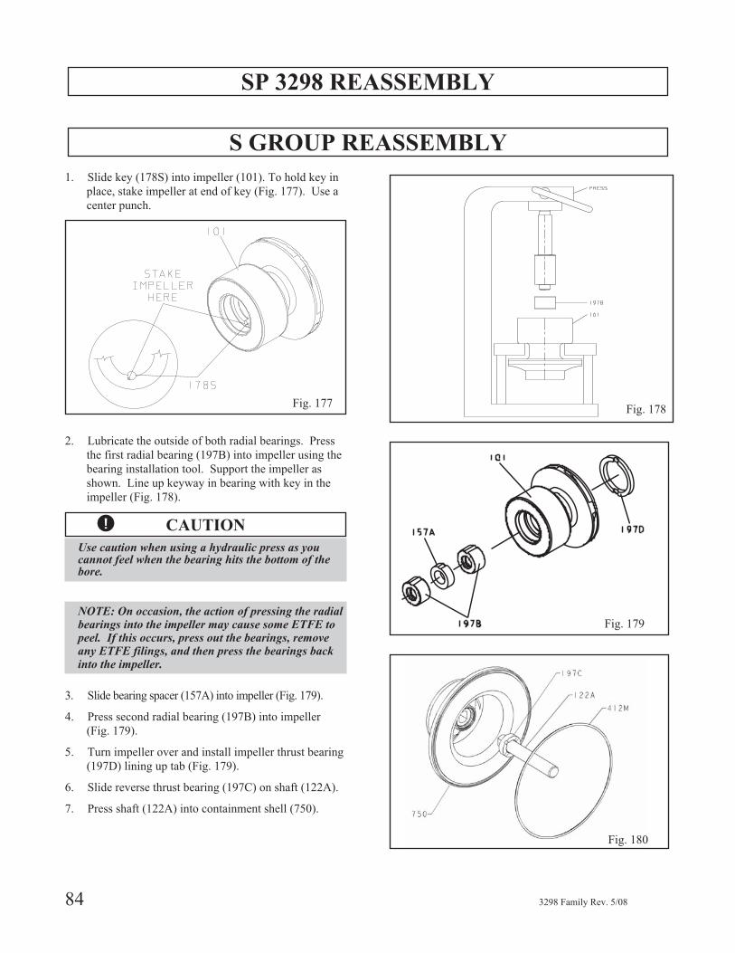
SP 3298 REASSEMBLY
S GROUP REASSEMBLY
1. Slide key (178S) into impeller (101). To hold key in
place, stake impeller at end of key (Fig. 177). Use a
center punch.
2. Lubricate the outside of both radial bearings. Press
the first radial bearing (197B) into impeller using the
bearing installation tool. Support the impeller as
shown. Line up keyway in bearing with key in the
impeller (Fig. 178).
� CAUTION
Use caution when using a hydraulic press as youcannot feel when the bearing hits the bottom of thebore.
NOTE: On occasion, the action of pressing the radialbearings into the impeller may cause some ETFE topeel. If this occurs, press out the bearings, removeany ETFE filings, and then press the bearings backinto the impeller.
3. Slide bearing spacer (157A) into impeller (Fig. 179).
4. Press second radial bearing (197B) into impeller
(Fig. 179).
5. Turn impeller over and install impeller thrust bearing
(197D) lining up tab (Fig. 179).
6. Slide reverse thrust bearing (197C) on shaft (122A).
7. Press shaft (122A) into containment shell (750).
84 3298 Family Rev. 5/08
Fig. 177Fig. 178
Fig. 179
Fig. 180
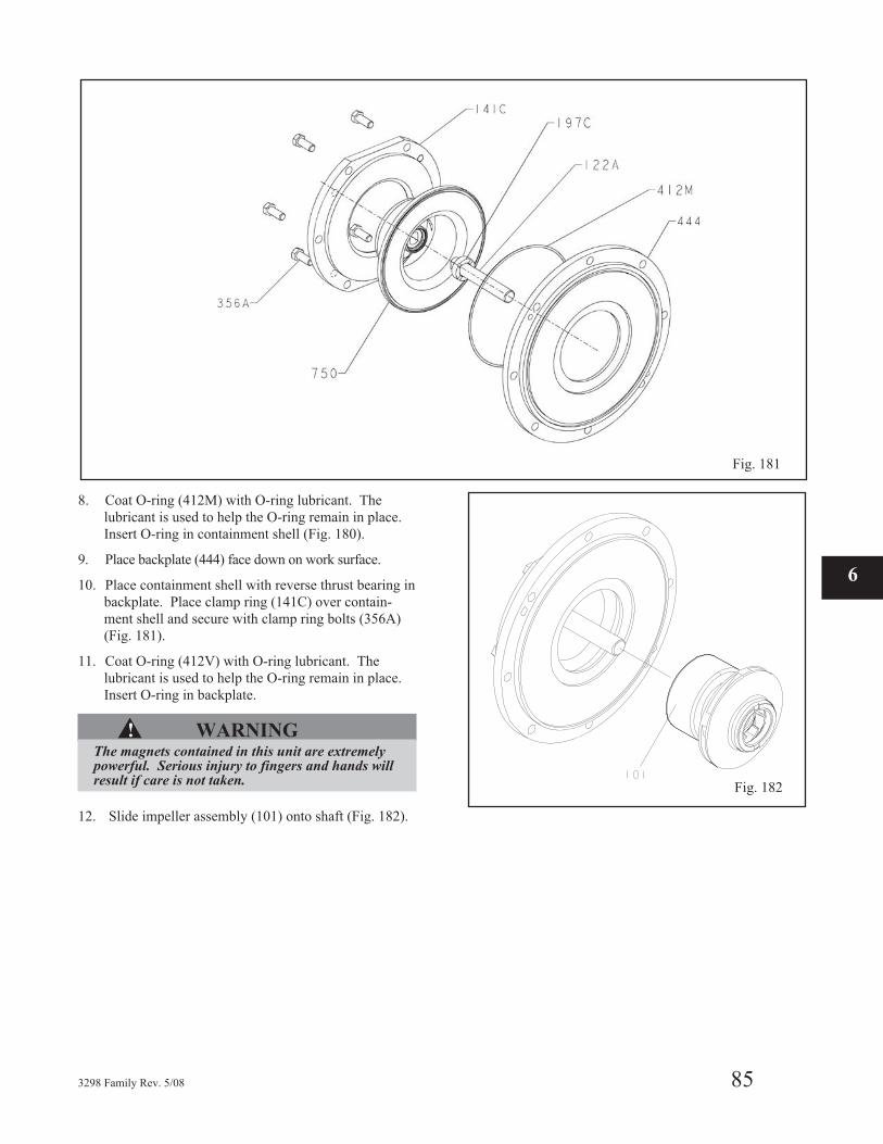
8. Coat O-ring (412M) with O-ring lubricant. The
lubricant is used to help the O-ring remain in place.
Insert O-ring in containment shell (Fig. 180).
9. Place backplate (444) face down on work surface.
10. Place containment shell with reverse thrust bearing in
backplate. Place clamp ring (141C) over contain-
ment shell and secure with clamp ring bolts (356A)
(Fig. 181).
11. Coat O-ring (412V) with O-ring lubricant. The
lubricant is used to help the O-ring remain in place.
Insert O-ring in backplate.
▲! WARNINGThe magnets contained in this unit are extremelypowerful. Serious injury to fingers and hands willresult if care is not taken.
12. Slide impeller assembly (101) onto shaft (Fig. 182).
3298 Family Rev. 5/08 85
6
Fig. 182
Fig. 181
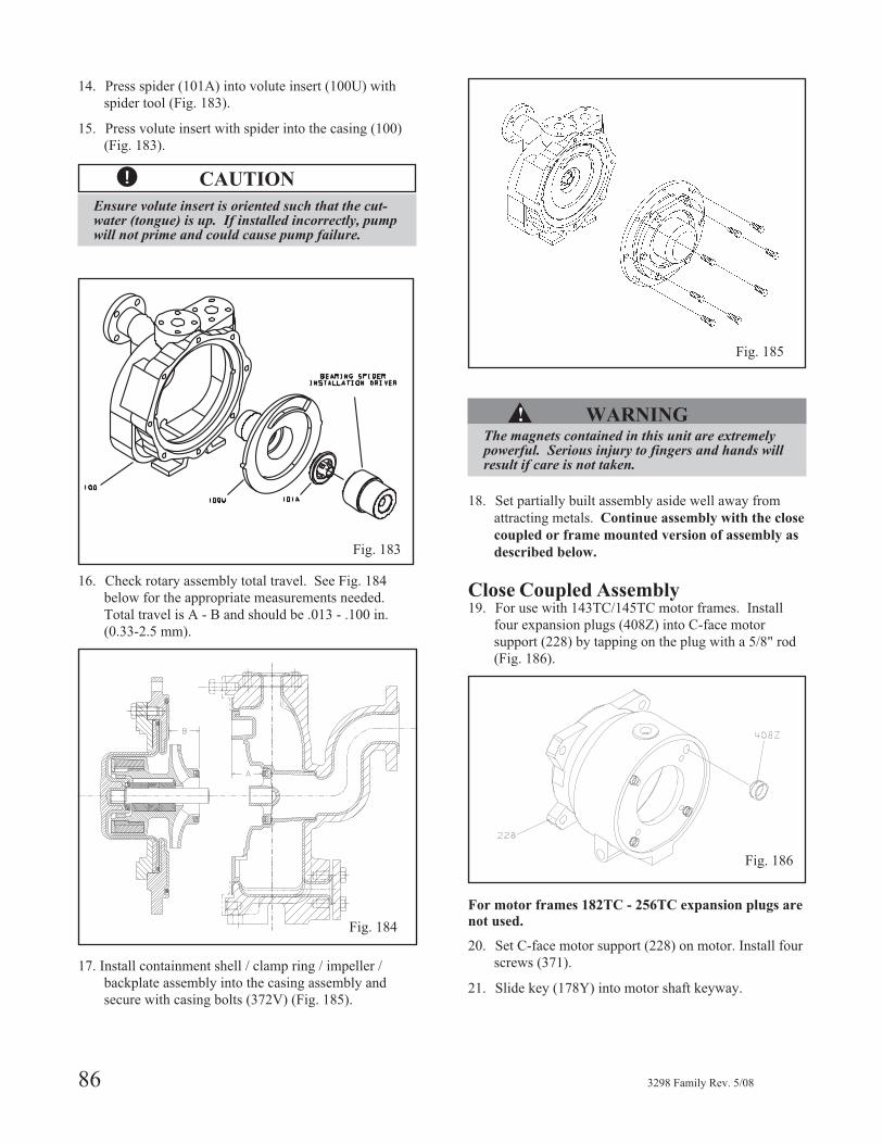
14. Press spider (101A) into volute insert (100U) with
spider tool (Fig. 183).
15. Press volute insert with spider into the casing (100)
(Fig. 183).
� CAUTION
Ensure volute insert is oriented such that the cut-water (tongue) is up. If installed incorrectly, pumpwill not prime and could cause pump failure.
16. Check rotary assembly total travel. See Fig. 184
below for the appropriate measurements needed.
Total travel is A - B and should be .013 - .100 in.
(0.33-2.5 mm).
17. Install containment shell / clamp ring / impeller /
backplate assembly into the casing assembly and
secure with casing bolts (372V) (Fig. 185).
▲! WARNINGThe magnets contained in this unit are extremelypowerful. Serious injury to fingers and hands willresult if care is not taken.
18. Set partially built assembly aside well away from
attracting metals. Continue assembly with the close
coupled or frame mounted version of assembly as
described below.
Close Coupled Assembly19. For use with 143TC/145TC motor frames. Install
four expansion plugs (408Z) into C-face motor
support (228) by tapping on the plug with a 5/8" rod
(Fig. 186).
For motor frames 182TC - 256TC expansion plugs are
not used.
20. Set C-face motor support (228) on motor. Install four
screws (371).
21. Slide key (178Y) into motor shaft keyway.
86 3298 Family Rev. 5/08
Fig. 183
Fig. 184
Fig. 185
Fig. 186
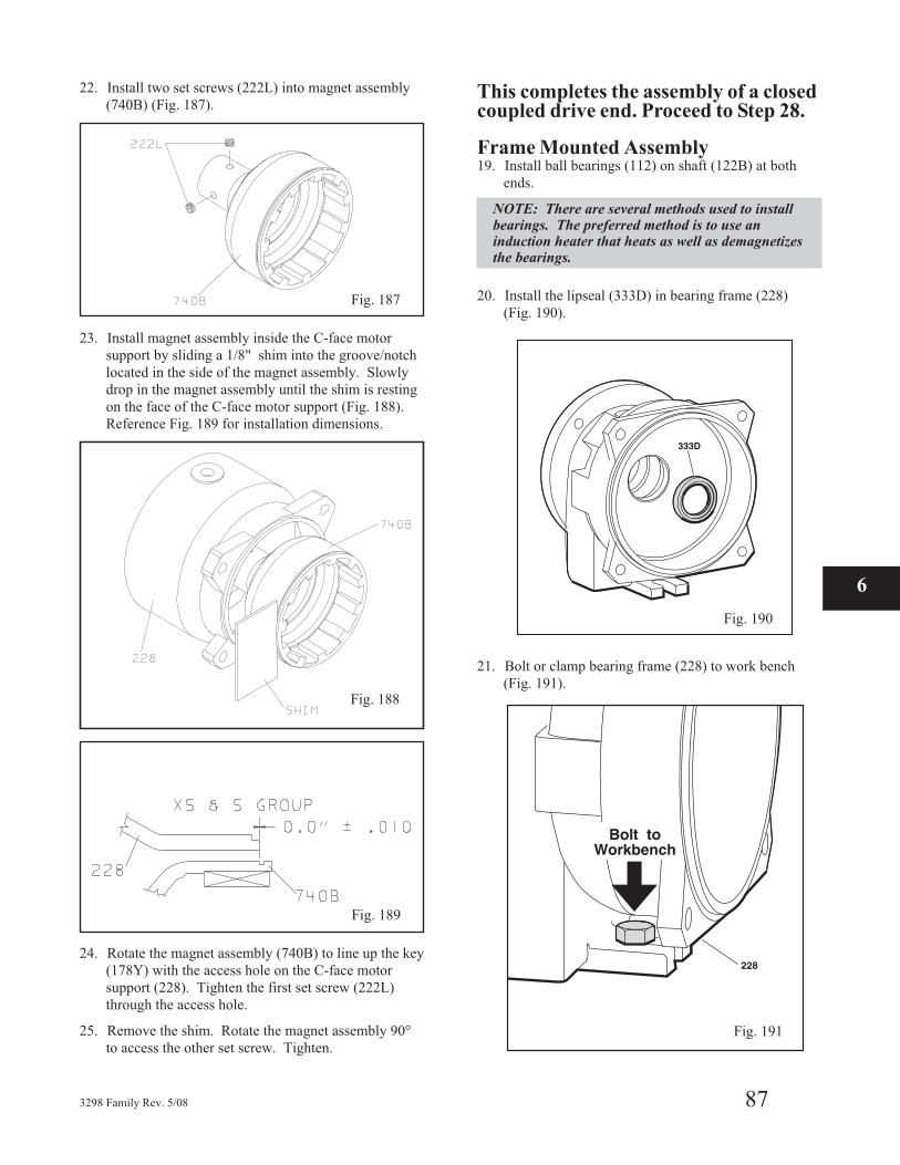
22. Install two set screws (222L) into magnet assembly
(740B) (Fig. 187).
23. Install magnet assembly inside the C-face motor
support by sliding a 1/8" shim into the groove/notch
located in the side of the magnet assembly. Slowly
drop in the magnet assembly until the shim is resting
on the face of the C-face motor support (Fig. 188).
Reference Fig. 189 for installation dimensions.
24. Rotate the magnet assembly (740B) to line up the key
(178Y) with the access hole on the C-face motor
support (228). Tighten the first set screw (222L)
through the access hole.
25. Remove the shim. Rotate the magnet assembly 90°
to access the other set screw. Tighten.
This completes the assembly of a closedcoupled drive end. Proceed to Step 28.
Frame Mounted Assembly19. Install ball bearings (112) on shaft (122B) at both
ends.
NOTE: There are several methods used to installbearings. The preferred method is to use aninduction heater that heats as well as demagnetizesthe bearings.
20. Install the lipseal (333D) in bearing frame (228)
(Fig. 190).
21. Bolt or clamp bearing frame (228) to work bench
(Fig. 191).
3298 Family Rev. 5/08 87
6
Fig. 187
Fig. 189
Fig. 190
Fig. 191
Fig. 188
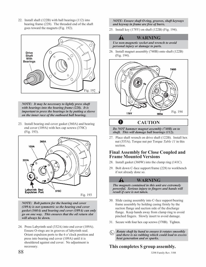
22. Install shaft (122B) with ball bearings (112) into
bearing frame (228). The threaded end of the shaft
goes toward the magnets (Fig. 192).
NOTE: It may be necessary to lightly press shaftwith bearings into the bearing frame (228). It isimportant to press the bearings in by putting a sleeveon the inner race of the outboard ball bearing.
23. Install bearing end cover gasket (360A) and bearing
end cover (109A) with hex cap screws (370C)
(Fig. 193).
NOTE: Bolt pattern for the bearing end cover(109A) is not symmetric so the bearing end covergasket (360A) and bearing end cover (109A) can onlygo on one way. This ensures that the oil return slotwill always be down.
24. Press Labyrinth seal (332A) into end cover (109A).
Ensure O-rings are in grooves of labyrinth seal.
Orient expulsion ports to the 6 o’clock position and
press into bearing end cover (109A) until it is
shouldered against end cover. No adjustment is
necessary.
NOTE: Ensure shaft O-ring, grooves, shaft keywaysand keyway in frame are free of burrs.
25. Install key (178Y) on shaft (122B) (Fig. 194).
▲! WARNINGUse non-magnetic socket and wrench to avoidpersonal injury or damage to parts.
26. Install magnet assembly (740B) onto shaft (122B)
(Fig. 194).
� CAUTION
Do NOT hammer magnet assembly (740B) on toshaft. This will damage ball bearings (112).
27. Place shaft wrench on drive shaft (122B). Install hex
nut (355A). Torque nut per Torque Table 11 in this
section.
Final Assembly for Close Coupled andFrame Mounted Versions28. Install gasket (360W) into the clamp ring (141C).
29. Bolt down C-face support/frame (228) to workbench
if not already done so.
▲! WARNINGThe magnets contained in this unit are extremelypowerful. Serious injury to fingers and hands willresult if care is not taken.
30. Slide casing assembly into C-face support/bearing
frame assembly by holding casing firmly by the
suction flange and suction side of the discharge
flange. Keep hands away from clamp ring to avoid
pinched fingers. Slowly insert to avoid damage.
31. Secure with four hex cap screws (370B). Tighten.
� Rotate shaft by hand to ensure it rotates smoothlyand there is no rubbing which could lead to excessheat generation and or sparks.
This completes S group assembly.
88 3298 Family Rev. 5/08
Fig. 192
Fig. 193
Fig. 194
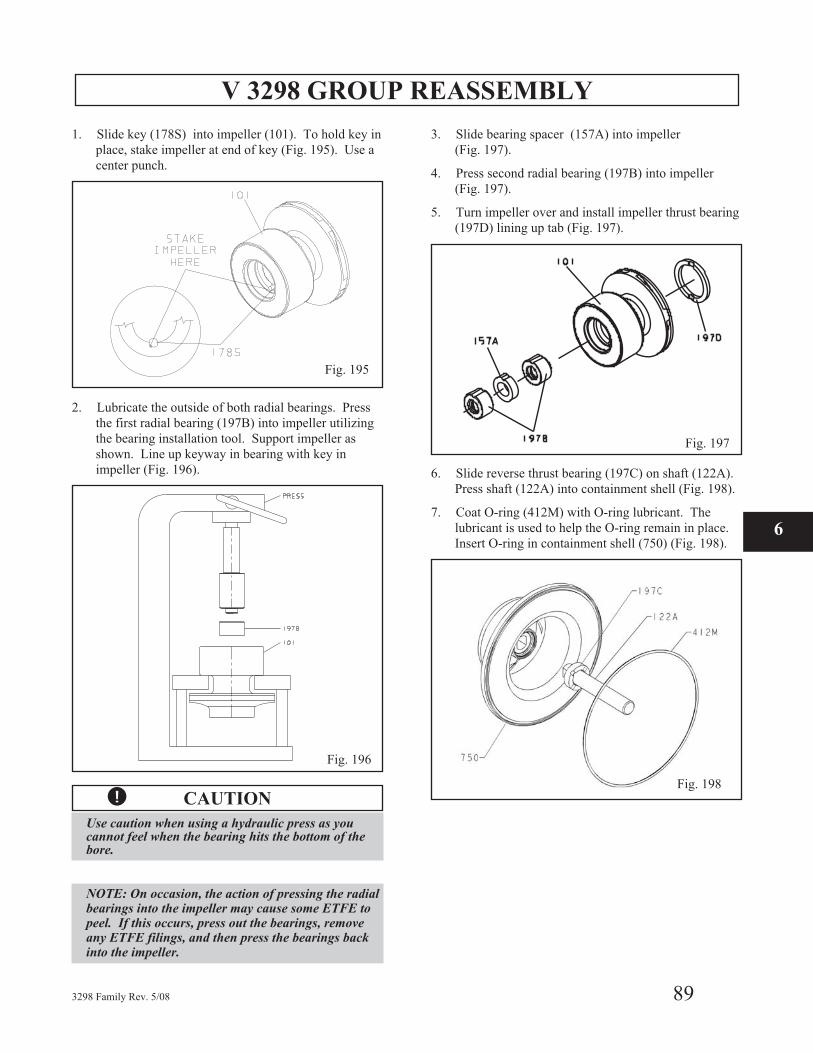
V 3298 GROUP REASSEMBLY
1. Slide key (178S) into impeller (101). To hold key in
place, stake impeller at end of key (Fig. 195). Use a
center punch.
2. Lubricate the outside of both radial bearings. Press
the first radial bearing (197B) into impeller utilizing
the bearing installation tool. Support impeller as
shown. Line up keyway in bearing with key in
impeller (Fig. 196).
� CAUTION
Use caution when using a hydraulic press as youcannot feel when the bearing hits the bottom of thebore.
NOTE: On occasion, the action of pressing the radialbearings into the impeller may cause some ETFE topeel. If this occurs, press out the bearings, removeany ETFE filings, and then press the bearings backinto the impeller.
3. Slide bearing spacer (157A) into impeller
(Fig. 197).
4. Press second radial bearing (197B) into impeller
(Fig. 197).
5. Turn impeller over and install impeller thrust bearing
(197D) lining up tab (Fig. 197).
6. Slide reverse thrust bearing (197C) on shaft (122A).
Press shaft (122A) into containment shell (Fig. 198).
7. Coat O-ring (412M) with O-ring lubricant. The
lubricant is used to help the O-ring remain in place.
Insert O-ring in containment shell (750) (Fig. 198).
3298 Family Rev. 5/08 89
6
Fig. 195
Fig. 196
Fig. 197
Fig. 198
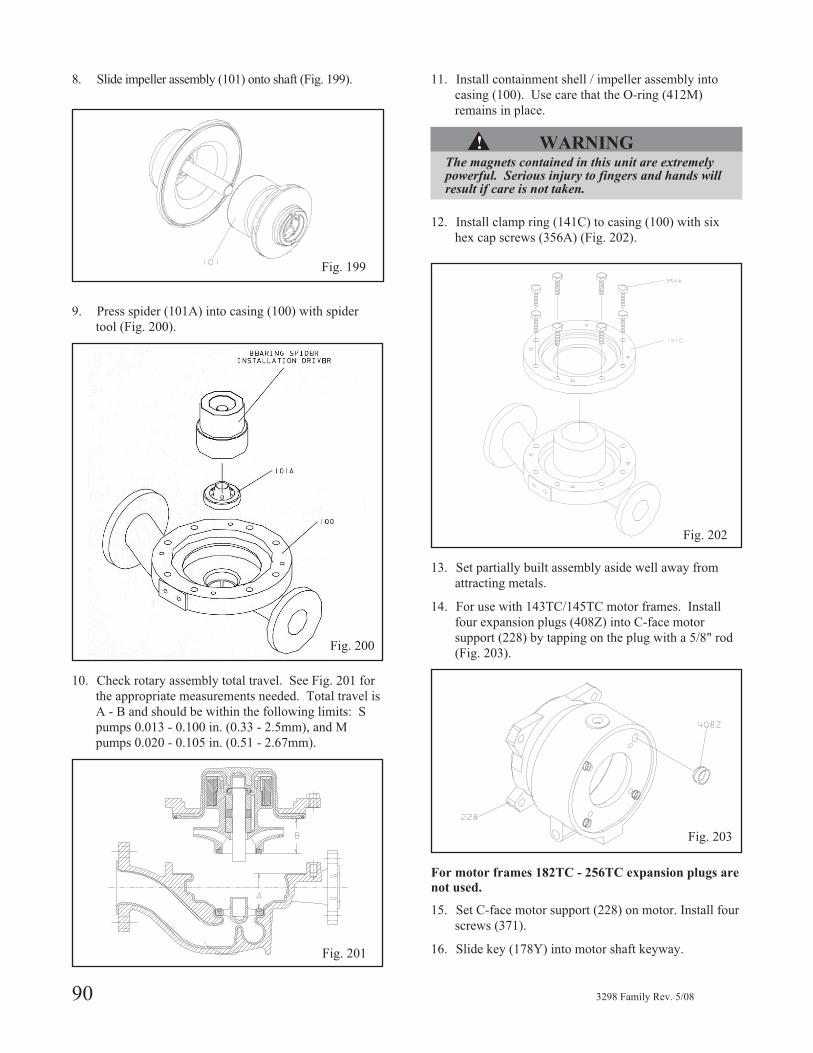
8. Slide impeller assembly (101) onto shaft (Fig. 199).
9. Press spider (101A) into casing (100) with spider
tool (Fig. 200).
10. Check rotary assembly total travel. See Fig. 201 for
the appropriate measurements needed. Total travel is
A - B and should be within the following limits: S
pumps 0.013 - 0.100 in. (0.33 - 2.5mm), and M
pumps 0.020 - 0.105 in. (0.51 - 2.67mm).
11. Install containment shell / impeller assembly into
casing (100). Use care that the O-ring (412M)
remains in place.
▲! WARNINGThe magnets contained in this unit are extremelypowerful. Serious injury to fingers and hands willresult if care is not taken.
12. Install clamp ring (141C) to casing (100) with six
hex cap screws (356A) (Fig. 202).
13. Set partially built assembly aside well away from
attracting metals.
14. For use with 143TC/145TC motor frames. Install
four expansion plugs (408Z) into C-face motor
support (228) by tapping on the plug with a 5/8" rod
(Fig. 203).
For motor frames 182TC - 256TC expansion plugs are
not used.
15. Set C-face motor support (228) on motor. Install four
screws (371).
16. Slide key (178Y) into motor shaft keyway.
90 3298 Family Rev. 5/08
Fig. 199
Fig. 200
Fig. 201
Fig. 202
Fig. 203
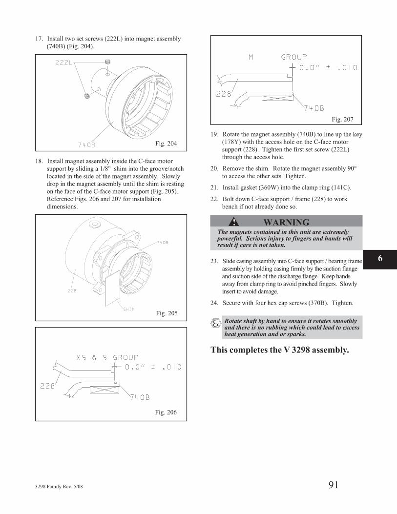
17. Install two set screws (222L) into magnet assembly
(740B) (Fig. 204).
18. Install magnet assembly inside the C-face motor
support by sliding a 1/8" shim into the groove/notch
located in the side of the magnet assembly. Slowly
drop in the magnet assembly until the shim is resting
on the face of the C-face motor support (Fig. 205).
Reference Figs. 206 and 207 for installation
dimensions.
19. Rotate the magnet assembly (740B) to line up the key
(178Y) with the access hole on the C-face motor
support (228). Tighten the first set screw (222L)
through the access hole.
20. Remove the shim. Rotate the magnet assembly 90°
to access the other sets. Tighten.
21. Install gasket (360W) into the clamp ring (141C).
22. Bolt down C-face support / frame (228) to work
bench if not already done so.
▲! WARNINGThe magnets contained in this unit are extremelypowerful. Serious injury to fingers and hands willresult if care is not taken.
23. Slide casing assembly into C-face support / bearing frame
assembly by holding casing firmly by the suction flange
and suction side of the discharge flange. Keep hands
away from clamp ring to avoid pinched fingers. Slowly
insert to avoid damage.
24. Secure with four hex cap screws (370B). Tighten.
� Rotate shaft by hand to ensure it rotates smoothlyand there is no rubbing which could lead to excessheat generation and or sparks.
This completes the V 3298 assembly.
3298 Family Rev. 5/08 91
6
Fig. 204
Fig. 205
Fig. 206
Fig. 207
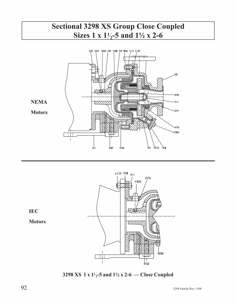
Sectional 3298 XS Group Close Coupled
Sizes 1 x 112-5 and 1½ x 2-6
92 3298 Family Rev. 5/08
NEMA
Motors
IEC
Motors
3298 XS 1 x 112-5 and 1½ x 2-6 — Close Coupled
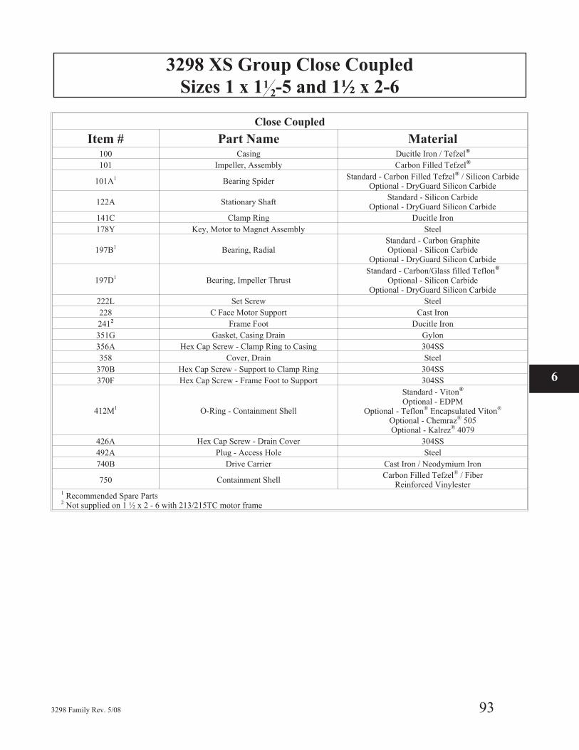
3298 XS Group Close Coupled
Sizes 1 x 112-5 and 1½ x 2-6
3298 Family Rev. 5/08 93
Close Coupled
Item # Part Name Material100 Casing Ducitle Iron / Tefzel®
101 Impeller, Assembly Carbon Filled Tefzel®
101A1 Bearing SpiderStandard - Carbon Filled Tefzel® / Silicon Carbide
Optional - DryGuard Silicon Carbide
122A Stationary ShaftStandard - Silicon Carbide
Optional - DryGuard Silicon Carbide
141C Clamp Ring Ducitle Iron
178Y Key, Motor to Magnet Assembly Steel
197B1 Bearing, RadialStandard - Carbon GraphiteOptional - Silicon Carbide
Optional - DryGuard Silicon Carbide
197D1 Bearing, Impeller ThrustStandard - Carbon/Glass filled Teflon®
Optional - Silicon CarbideOptional - DryGuard Silicon Carbide
222L Set Screw Steel
228 C Face Motor Support Cast Iron
2412 Frame Foot Ducitle Iron
351G Gasket, Casing Drain Gylon
356A Hex Cap Screw - Clamp Ring to Casing 304SS
358 Cover, Drain Steel
370B Hex Cap Screw - Support to Clamp Ring 304SS
370F Hex Cap Screw - Frame Foot to Support 304SS
412M1 O-Ring - Containment Shell
Standard - Viton®
Optional - EDPMOptional - Teflon® Encapsulated Viton®
Optional - Chemraz® 505Optional - Kalrez® 4079
426A Hex Cap Screw - Drain Cover 304SS
492A Plug - Access Hole Steel
740B Drive Carrier Cast Iron / Neodymium Iron
750 Containment ShellCarbon Filled Tefzel® / Fiber
Reinforced Vinylester1 Recommended Spare Parts2 Not supplied on 1 ½ x 2 - 6 with 213/215TC motor frame
6
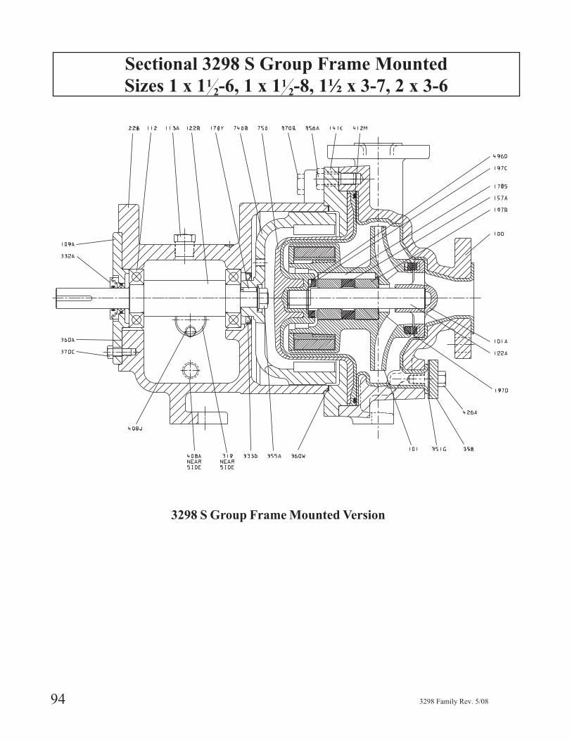
Sectional 3298 S Group Frame Mounted
Sizes 1 x 112-6, 1 x 11
2-8, 1½ x 3-7, 2 x 3-6
94 3298 Family Rev. 5/08
3298 S Group Frame Mounted Version
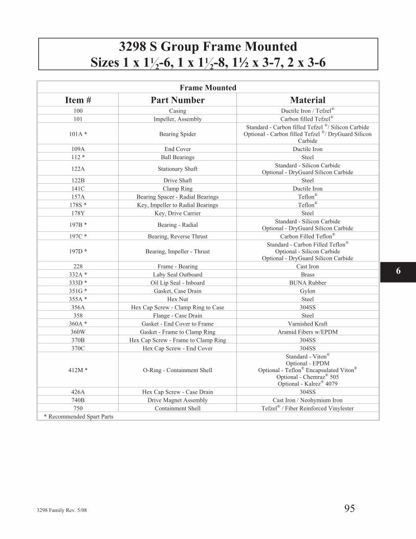
3298 S Group Frame Mounted
Sizes 1 x 112-6, 1 x 11
2-8, 1½ x 3-7, 2 x 3-6
3298 Family Rev. 5/08 95
Frame Mounted
Item # Part Number Material100 Casing Ductile Iron / Tefzel®
101 Impeller, Assembly Carbon filled Tefzel®
101A * Bearing SpiderStandard - Carbon filled Tefzel ®/ Silicon Carbide
Optional - Carbon filled Tefzel ®/ DryGuard SiliconCarbide
109A End Cover Ductile Iron
112 * Ball Bearings Steel
122A Stationary ShaftStandard - Silicon Carbide
Optional - DryGuard Silicon Carbide
122B Drive Shaft Steel
141C Clamp Ring Ductile Iron
157A Bearing Spacer - Radial Bearings Teflon®
178S * Key, Impeller to Radial Bearings Teflon®
178Y Key, Drive Carrier Steel
197B * Bearing - RadialStandard - Silicon Carbide
Optional - DryGuard Silicon Carbide
197C * Bearing, Reverse Thrust Carbon Filled Teflon®
197D * Bearing, Impeller - ThrustStandard - Carbon Filled Teflon®
Optional - Silicon CarbideOptional - DryGuard Silicon Carbide
228 Frame - Bearing Cast Iron
332A * Laby Seal Outboard Brass
333D * Oil Lip Seal - Inboard BUNA Rubber
351G * Gasket, Case Drain Gylon
355A * Hex Nut Steel
356A Hex Cap Screw - Clamp Ring to Case 304SS
358 Flange - Case Drain Steel
360A * Gasket - End Cover to Frame Varnished Kraft
360W Gasket - Frame to Clamp Ring Aramid Fibers w/EPDM
370B Hex Cap Screw - Frame to Clamp Ring 304SS
370C Hex Cap Screw - End Cover 304SS
412M * O-Ring - Containment Shell
Standard - Viton®
Optional - EPDMOptional - Teflon® Encapsulated Viton®
Optional - Chemraz® 505Optional - Kalrez® 4079
426A Hex Cap Screw - Case Drain 304SS
740B Drive Magnet Assembly Cast Iron / Neohymium Iron
750 Containment Shell Tefzel® / Fiber Reinforced Vinylester
* Recommended Spart Parts
6
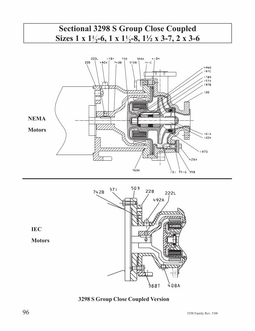
Sectional 3298 S Group Close Coupled
Sizes 1 x 112-6, 1 x 11
2-8, 1½ x 3-7, 2 x 3-6
96 3298 Family Rev. 5/08
3298 S Group Close Coupled Version
IEC
Motors
NEMA
Motors

3298 S Group Close Coupled
Sizes 1 x 112-6, 1 x 11
2-8, 1½ x 3-7, 2 x 3-6
3298 Family Rev. 5/08 97
3298 S Group Close Coupled
ItemNumber Part Name Material
100 Casing Ductile Iron / Tefzel®
101 Impeller, Assembly Carbon Filled Tefzel®
101A * Bearing SpiderStandard - Carbon filled Tefzel® / Silicon CarbideOptional - Carbon filled Tefzel / DryGuard Silicon
Carbide
122A Stationary ShaftStandard - Silicon Carbide
Optional - DryGuard Silicon Carbide141C Clamp Ring Ductile Iron157A Bearing Spacer - Radial Bearings Teflon®
178S * Key, Impeller to Radial Bearings Teflon®
178Y Key, Motor to Carrier Steel
197B * Bearing - RadialStandard - Carbon GraphiteOptional - Silicon Carbide
Optional - DryGuard Silicon Carbide197C * Bearing, Reverse Thrust Carbon Filled Teflon®
197D * Bearing, Impeller - ThrustCarbon Filled Teflon®
Optional - Silicon CarbideOptional - DryGuard Silicon Carbide
222L Set Screw Steel228 Motor Support - Close Coupled Cast Iron
351G * Gasket, Case Drain Gylon356A Hex Cap Screw - Clamp Ring to Case 304SS358 Flange - Case Drain Steel
360W * Gasket - Motor Support to Clamp Ring Aramid Fibers w/EPDM370B Hex Cap Screw - Motor Support to Clamp Ring 304SS
412M * O-Ring - Containment Shell
Standard - Viton®
Optional - EPDMOptional - Teflon® Encapsulated Viton®
Optional - Chemraz® 505Optional - Kalrez® 4079
426A Hex Cap Screw - Case Drain 304SS492A Access Hole Plug Steel740B Drive Magnet Assembly Cast Iron / Neohymium Iron750 Containment Shell Tefzel ®/ Fiber Reinforced Vinylester
* Recommended Spare Parts
ItemNumber Part Name Material
228 Frame, Close Coupled (IEC) Ductile Iron333L Screw, Set 304SS371 H.C. Screw - Motor to Frame Carbon Steel
388T H.C. Screw - Adapt to Frame 1 Carbon Steel408A Plug - Drain Carbon Steel492A Plug - Access Hole Carbon Steel503 Ring, Adapter 1 Cast Iron
742B Ring, Centering 2 Carbon Steel1 Used with Motor Frames 132 & 160 only.2 Used with Motor Frames 80 & 90 only.
6
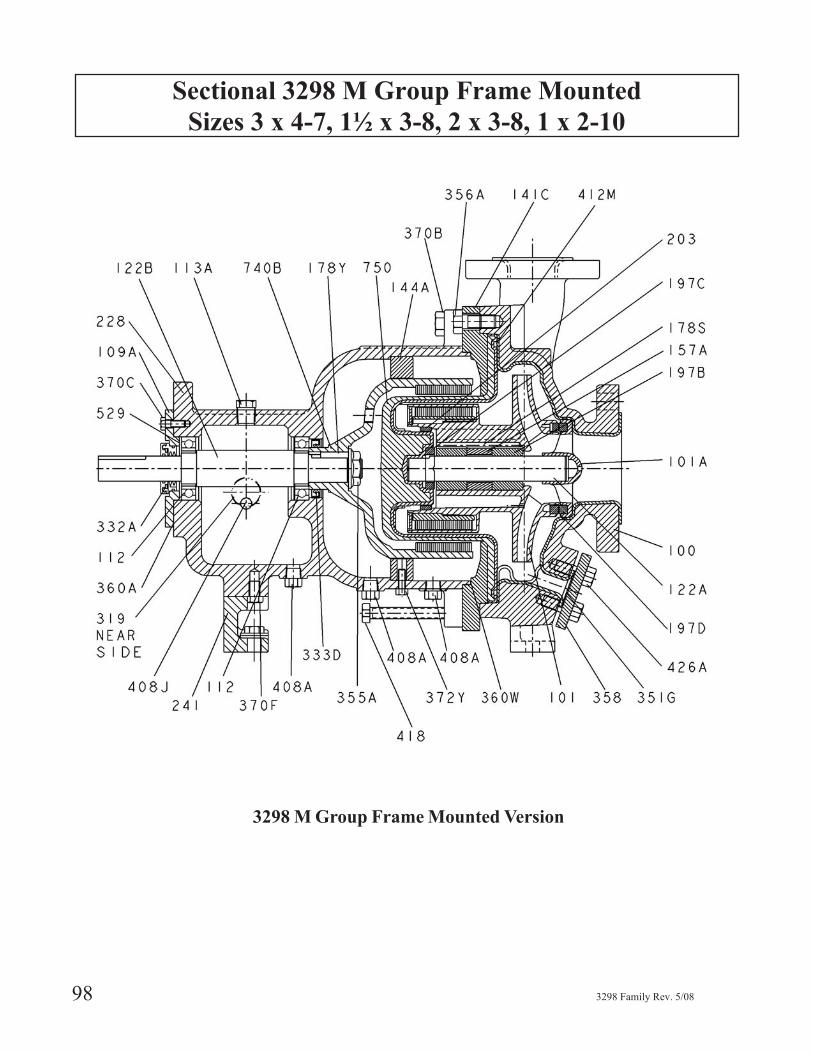
Sectional 3298 M Group Frame Mounted
Sizes 3 x 4-7, 1½ x 3-8, 2 x 3-8, 1 x 2-10
98 3298 Family Rev. 5/08
3298 M Group Frame Mounted Version
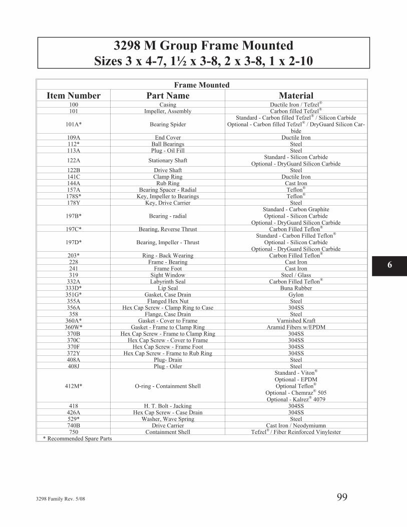
3298 M Group Frame Mounted
Sizes 3 x 4-7, 1½ x 3-8, 2 x 3-8, 1 x 2-10
3298 Family Rev. 5/08 99
Frame Mounted
Item Number Part Name Material100 Casing Ductile Iron / Tefzel®
101 Impeller, Assembly Carbon filled Tefzel®
101A* Bearing SpiderStandard - Carbon filled Tefzel® / Silicon Carbide
Optional - Carbon filled Tefzel® / DryGuard Silicon Car-bide
109A End Cover Ductile Iron112* Ball Bearings Steel113A Plug - Oil Fill Steel
122A Stationary ShaftStandard - Silicon Carbide
Optional - DryGuard Silicon Carbide122B Drive Shaft Steel141C Clamp Ring Ductile Iron144A Rub Ring Cast Iron157A Bearing Spacer - Radial Teflon®
178S* Key, Impeller to Bearings Teflon®
178Y Key, Drive Carrier Steel
197B* Bearing - radialStandard - Carbon GraphiteOptional - Silicon Carbide
Optional - DryGuard Silicon Carbide197C* Bearing, Reverse Thrust Carbon Filled Teflon®
197D* Bearing, Impeller - ThrustStandard - Carbon Filled Teflon®
Optional - Silicon CarbideOptional - DryGuard Silicon Carbide
203* Ring - Back Wearing Carbon Filled Teflon®
228 Frame - Bearing Cast Iron241 Frame Foot Cast Iron319 Sight Window Steel / Glass
332A Labyrinth Seal Carbon Filled Teflon®
333D* Lip Seal Buna Rubber351G* Gasket, Case Drain Gylon355A Flanged Hex Nut Steel356A Hex Cap Screw - Clamp Ring to Case 304SS358 Flange, Case Drain Steel
360A* Gasket - Cover to Frame Varnished Kraft360W* Gasket - Frame to Clamp Ring Aramid Fibers w/EPDM370B Hex Cap Screw - Frame to Clamp Ring 304SS370C Hex Cap Screw - Cover to Frame 304SS370F Hex Cap Screw - Frame Foot 304SS372Y Hex Cap Screw - Frame to Rub Ring 304SS408A Plug- Drain Steel408J Plug - Oiler Steel
412M* O-ring - Containment Shell
Standard - Viton®
Optional - EPDMOptional Teflon®
Optional - Chemraz® 505Optional - Kalrez® 4079
418 H. T. Bolt - Jacking 304SS426A Hex Cap Screw - Case Drain 304SS529* Washer, Wave Spring Steel740B Drive Carrier Cast Iron / Neodymiumn750 Containment Shell Tefzel® / Fiber Reinforced Vinylester
* Recommended Spare Parts
6
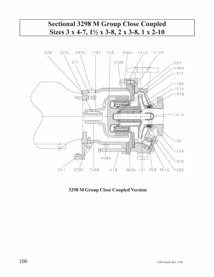
Sectional 3298 M Group Close Coupled
Sizes 3 x 4-7, 1½ x 3-8, 2 x 3-8, 1 x 2-10
100 3298 Family Rev. 5/08
3298 M Group Close Coupled Version
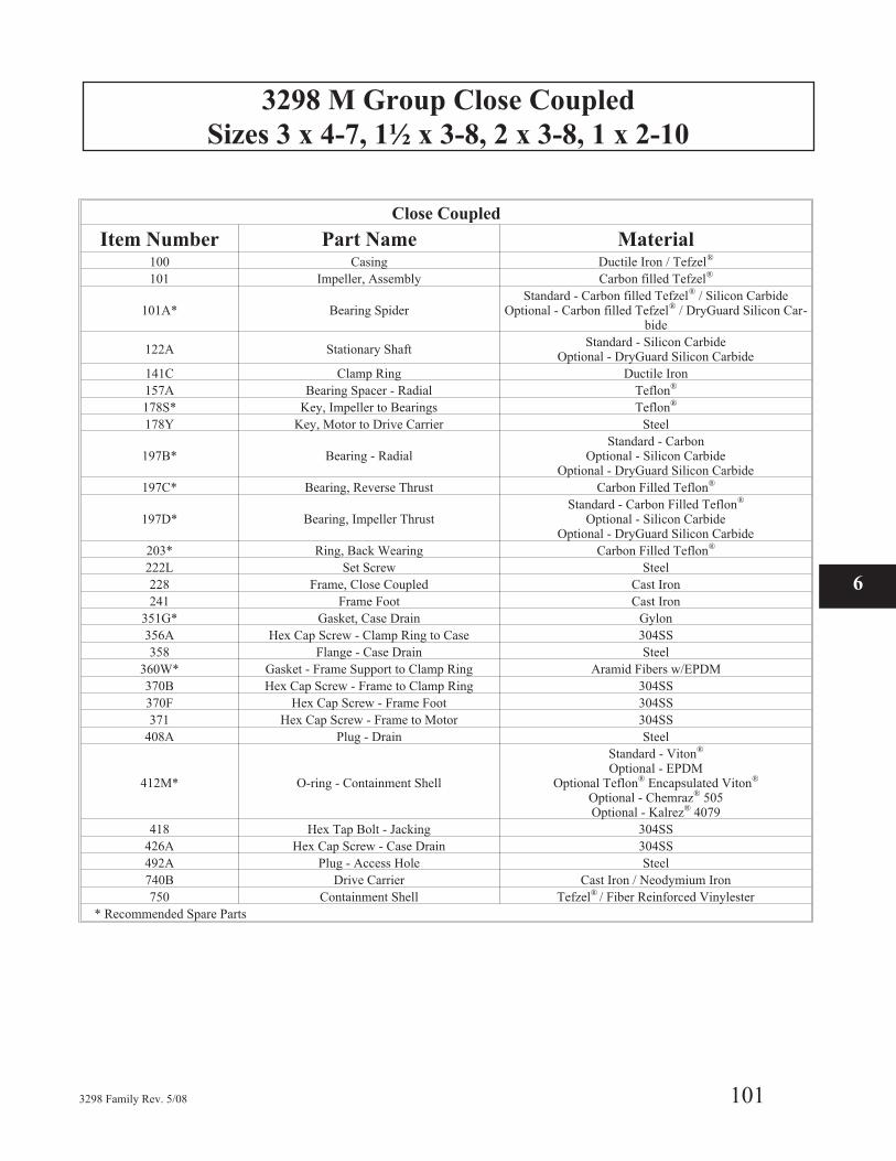
3298 M Group Close Coupled
Sizes 3 x 4-7, 1½ x 3-8, 2 x 3-8, 1 x 2-10
3298 Family Rev. 5/08 101
Close Coupled
Item Number Part Name Material100 Casing Ductile Iron / Tefzel®
101 Impeller, Assembly Carbon filled Tefzel®
101A* Bearing SpiderStandard - Carbon filled Tefzel® / Silicon Carbide
Optional - Carbon filled Tefzel® / DryGuard Silicon Car-bide
122A Stationary ShaftStandard - Silicon Carbide
Optional - DryGuard Silicon Carbide
141C Clamp Ring Ductile Iron
157A Bearing Spacer - Radial Teflon®
178S* Key, Impeller to Bearings Teflon®
178Y Key, Motor to Drive Carrier Steel
197B* Bearing - RadialStandard - Carbon
Optional - Silicon CarbideOptional - DryGuard Silicon Carbide
197C* Bearing, Reverse Thrust Carbon Filled Teflon®
197D* Bearing, Impeller ThrustStandard - Carbon Filled Teflon®
Optional - Silicon CarbideOptional - DryGuard Silicon Carbide
203* Ring, Back Wearing Carbon Filled Teflon®
222L Set Screw Steel
228 Frame, Close Coupled Cast Iron
241 Frame Foot Cast Iron
351G* Gasket, Case Drain Gylon
356A Hex Cap Screw - Clamp Ring to Case 304SS
358 Flange - Case Drain Steel
360W* Gasket - Frame Support to Clamp Ring Aramid Fibers w/EPDM
370B Hex Cap Screw - Frame to Clamp Ring 304SS
370F Hex Cap Screw - Frame Foot 304SS
371 Hex Cap Screw - Frame to Motor 304SS
408A Plug - Drain Steel
412M* O-ring - Containment Shell
Standard - Viton®
Optional - EPDMOptional Teflon® Encapsulated Viton®
Optional - Chemraz® 505Optional - Kalrez® 4079
418 Hex Tap Bolt - Jacking 304SS
426A Hex Cap Screw - Case Drain 304SS
492A Plug - Access Hole Steel
740B Drive Carrier Cast Iron / Neodymium Iron
750 Containment Shell Tefzel® / Fiber Reinforced Vinylester
* Recommended Spare Parts
6
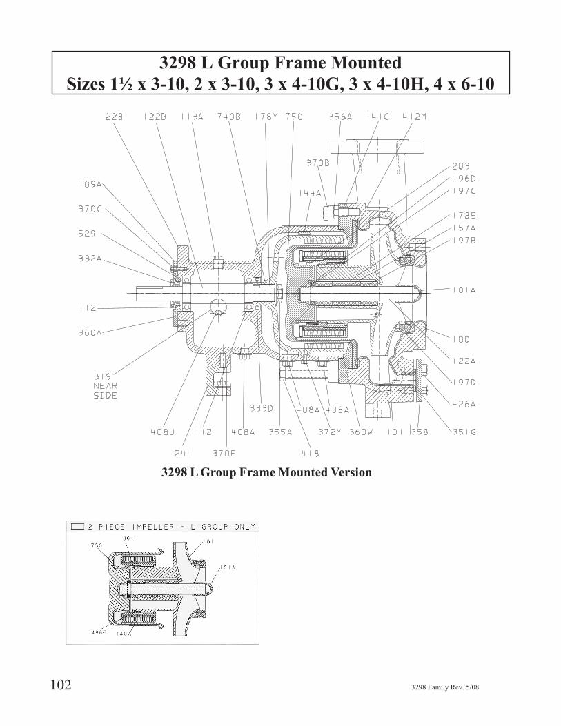
3298 L Group Frame Mounted
Sizes 1½ x 3-10, 2 x 3-10, 3 x 4-10G, 3 x 4-10H, 4 x 6-10
102 3298 Family Rev. 5/08
3298 L Group Frame Mounted Version
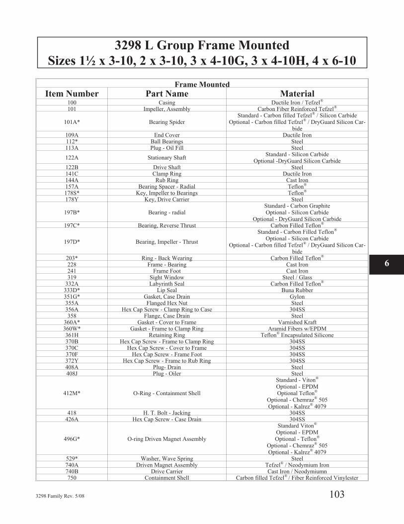
3298 L Group Frame Mounted
Sizes 1½ x 3-10, 2 x 3-10, 3 x 4-10G, 3 x 4-10H, 4 x 6-10
3298 Family Rev. 5/08 103
6
Frame Mounted
Item Number Part Name Material100 Casing Ductile Iron / Tefzel®
101 Impeller, Assembly Carbon Fiber Reinforced Tefzel®
101A* Bearing SpiderStandard - Carbon filled Tefzel® / Silicon Carbide
Optional - Carbon filled Tefzel® / DryGuard Silicon Car-bide
109A End Cover Ductile Iron112* Ball Bearings Steel113A Plug - Oil Fill Steel
122A Stationary ShaftStandard - Silicon Carbide
Optional -DryGuard Silicon Carbide122B Drive Shaft Steel141C Clamp Ring Ductile Iron144A Rub Ring Cast Iron157A Bearing Spacer - Radial Teflon®
178S* Key, Impeller to Bearings Teflon®
178Y Key, Drive Carrier Steel
197B* Bearing - radialStandard - Carbon GraphiteOptional - Silicon Carbide
Optional - DryGuard Silicon Carbide197C* Bearing, Reverse Thrust Carbon Filled Teflon®
197D* Bearing, Impeller - Thrust
Standard - Carbon Filled Teflon®
Optional - Silicon CarbideOptional - Carbon filled Tefzel® / DryGuard Silicon Car-
bide203* Ring - Back Wearing Carbon Filled Teflon®
228 Frame - Bearing Cast Iron241 Frame Foot Cast Iron319 Sight Window Steel / Glass
332A Labyrinth Seal Carbon Filled Teflon®
333D* Lip Seal Buna Rubber351G* Gasket, Case Drain Gylon355A Flanged Hex Nut Steel356A Hex Cap Screw - Clamp Ring to Case 304SS358 Flange, Case Drain Steel
360A* Gasket - Cover to Frame Varnished Kraft360W* Gasket - Frame to Clamp Ring Aramid Fibers w/EPDM361H Retaining Ring Teflon® Encapsulated Silicone370B Hex Cap Screw - Frame to Clamp Ring 304SS370C Hex Cap Screw - Cover to Frame 304SS370F Hex Cap Screw - Frame Foot 304SS372Y Hex Cap Screw - Frame to Rub Ring 304SS408A Plug- Drain Steel408J Plug - Oiler Steel
412M* O-Ring - Containment Shell
Standard - Viton®
Optional - EPDMOptional Teflon®
Optional - Chemraz® 505Optional - Kalrez® 4079
418 H. T. Bolt - Jacking 304SS426A Hex Cap Screw - Case Drain 304SS
496G* O-ring Driven Magnet Assembly
Standard Viton®
Optional - EPDMOptional - Teflon®
Optional - Chemraz® 505Optional - Kalrez® 4079
529* Washer, Wave Spring Steel740A Driven Magnet Assembly Tefzel® / Neodymium Iron740B Drive Carrier Cast Iron / Neodymiumn750 Containment Shell Carbon filled Tefzel® / Fiber Reinforced Vinylester
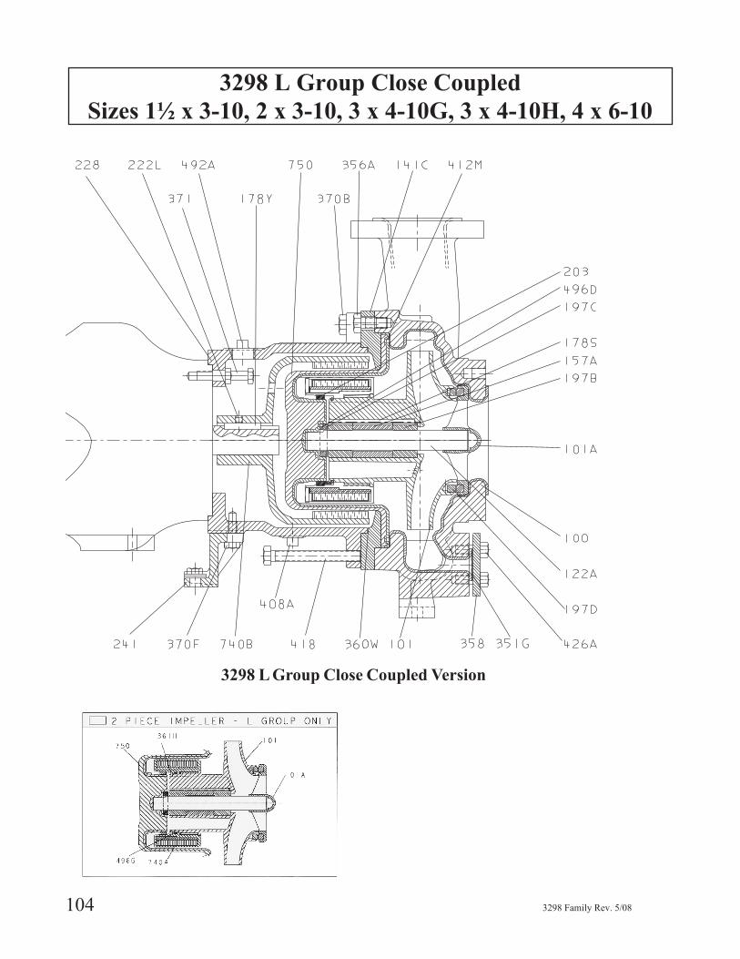
3298 L Group Close Coupled
Sizes 1½ x 3-10, 2 x 3-10, 3 x 4-10G, 3 x 4-10H, 4 x 6-10
104 3298 Family Rev. 5/08
3298 L Group Close Coupled Version
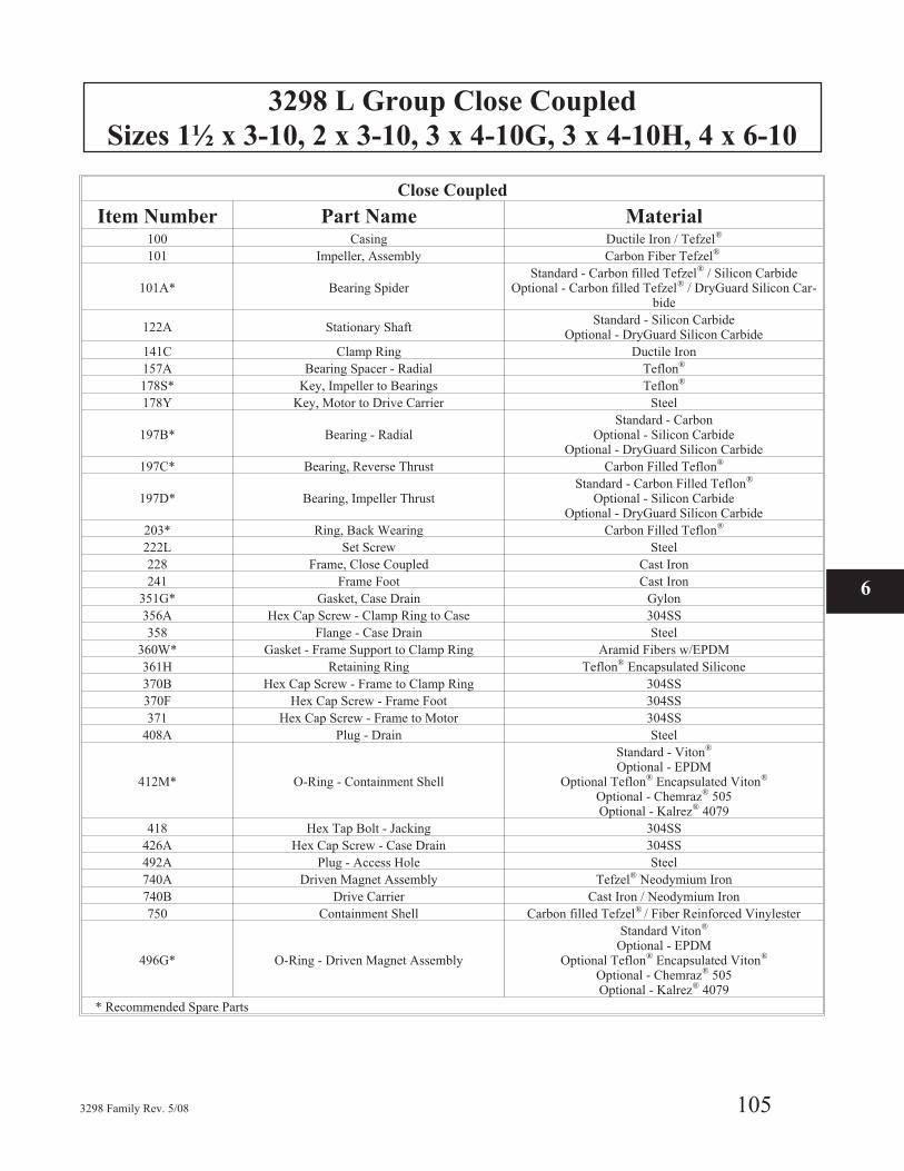
3298 L Group Close Coupled
Sizes 1½ x 3-10, 2 x 3-10, 3 x 4-10G, 3 x 4-10H, 4 x 6-10
3298 Family Rev. 5/08 105
Close Coupled
Item Number Part Name Material100 Casing Ductile Iron / Tefzel®
101 Impeller, Assembly Carbon Fiber Tefzel®
101A* Bearing SpiderStandard - Carbon filled Tefzel® / Silicon Carbide
Optional - Carbon filled Tefzel® / DryGuard Silicon Car-bide
122A Stationary ShaftStandard - Silicon Carbide
Optional - DryGuard Silicon Carbide
141C Clamp Ring Ductile Iron
157A Bearing Spacer - Radial Teflon®
178S* Key, Impeller to Bearings Teflon®
178Y Key, Motor to Drive Carrier Steel
197B* Bearing - RadialStandard - Carbon
Optional - Silicon CarbideOptional - DryGuard Silicon Carbide
197C* Bearing, Reverse Thrust Carbon Filled Teflon®
197D* Bearing, Impeller ThrustStandard - Carbon Filled Teflon®
Optional - Silicon CarbideOptional - DryGuard Silicon Carbide
203* Ring, Back Wearing Carbon Filled Teflon®
222L Set Screw Steel
228 Frame, Close Coupled Cast Iron
241 Frame Foot Cast Iron
351G* Gasket, Case Drain Gylon
356A Hex Cap Screw - Clamp Ring to Case 304SS
358 Flange - Case Drain Steel
360W* Gasket - Frame Support to Clamp Ring Aramid Fibers w/EPDM
361H Retaining Ring Teflon® Encapsulated Silicone
370B Hex Cap Screw - Frame to Clamp Ring 304SS
370F Hex Cap Screw - Frame Foot 304SS
371 Hex Cap Screw - Frame to Motor 304SS
408A Plug - Drain Steel
412M* O-Ring - Containment Shell
Standard - Viton®
Optional - EPDMOptional Teflon® Encapsulated Viton®
Optional - Chemraz® 505Optional - Kalrez® 4079
418 Hex Tap Bolt - Jacking 304SS
426A Hex Cap Screw - Case Drain 304SS
492A Plug - Access Hole Steel
740A Driven Magnet Assembly Tefzel® Neodymium Iron
740B Drive Carrier Cast Iron / Neodymium Iron
750 Containment Shell Carbon filled Tefzel® / Fiber Reinforced Vinylester
496G* O-Ring - Driven Magnet Assembly
Standard Viton®
Optional - EPDMOptional Teflon® Encapsulated Viton®
Optional - Chemraz® 505Optional - Kalrez® 4079
* Recommended Spare Parts
6
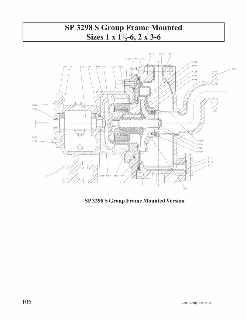
SP 3298 S Group Frame Mounted
Sizes 1 x 112-6, 2 x 3-6
106 3298 Family Rev. 5/08
SP 3298 S Group Frame Mounted Version
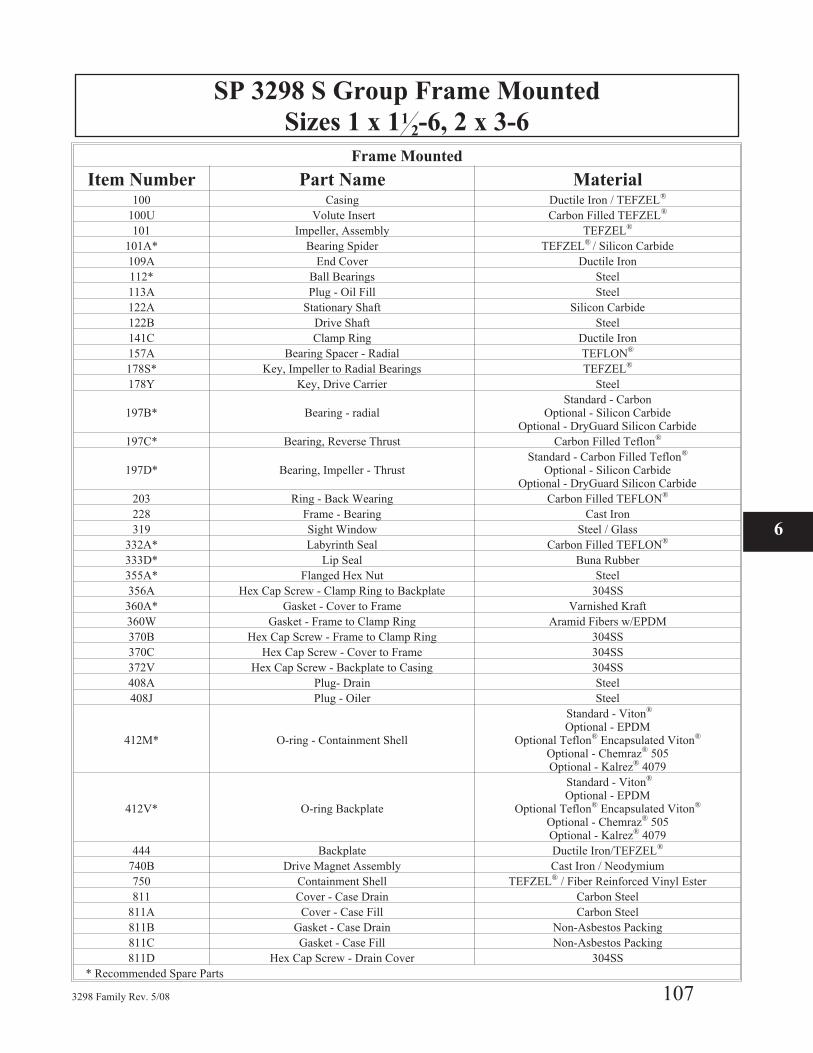
SP 3298 S Group Frame Mounted
Sizes 1 x 112-6, 2 x 3-6
3298 Family Rev. 5/08 107
Frame Mounted
Item Number Part Name Material100 Casing Ductile Iron / TEFZEL®
100U Volute Insert Carbon Filled TEFZEL®
101 Impeller, Assembly TEFZEL®
101A* Bearing Spider TEFZEL® / Silicon Carbide
109A End Cover Ductile Iron
112* Ball Bearings Steel
113A Plug - Oil Fill Steel
122A Stationary Shaft Silicon Carbide
122B Drive Shaft Steel
141C Clamp Ring Ductile Iron
157A Bearing Spacer - Radial TEFLON®
178S* Key, Impeller to Radial Bearings TEFZEL®
178Y Key, Drive Carrier Steel
197B* Bearing - radialStandard - Carbon
Optional - Silicon CarbideOptional - DryGuard Silicon Carbide
197C* Bearing, Reverse Thrust Carbon Filled Teflon®
197D* Bearing, Impeller - ThrustStandard - Carbon Filled Teflon®
Optional - Silicon CarbideOptional - DryGuard Silicon Carbide
203 Ring - Back Wearing Carbon Filled TEFLON®
228 Frame - Bearing Cast Iron
319 Sight Window Steel / Glass
332A* Labyrinth Seal Carbon Filled TEFLON®
333D* Lip Seal Buna Rubber
355A* Flanged Hex Nut Steel
356A Hex Cap Screw - Clamp Ring to Backplate 304SS
360A* Gasket - Cover to Frame Varnished Kraft
360W Gasket - Frame to Clamp Ring Aramid Fibers w/EPDM
370B Hex Cap Screw - Frame to Clamp Ring 304SS
370C Hex Cap Screw - Cover to Frame 304SS
372V Hex Cap Screw - Backplate to Casing 304SS
408A Plug- Drain Steel
408J Plug - Oiler Steel
412M* O-ring - Containment Shell
Standard - Viton®
Optional - EPDMOptional Teflon® Encapsulated Viton®
Optional - Chemraz® 505Optional - Kalrez® 4079
412V* O-ring Backplate
Standard - Viton®
Optional - EPDMOptional Teflon® Encapsulated Viton®
Optional - Chemraz® 505Optional - Kalrez® 4079
444 Backplate Ductile Iron/TEFZEL®
740B Drive Magnet Assembly Cast Iron / Neodymium
750 Containment Shell TEFZEL® / Fiber Reinforced Vinyl Ester
811 Cover - Case Drain Carbon Steel
811A Cover - Case Fill Carbon Steel
811B Gasket - Case Drain Non-Asbestos Packing
811C Gasket - Case Fill Non-Asbestos Packing
811D Hex Cap Screw - Drain Cover 304SS
* Recommended Spare Parts
6
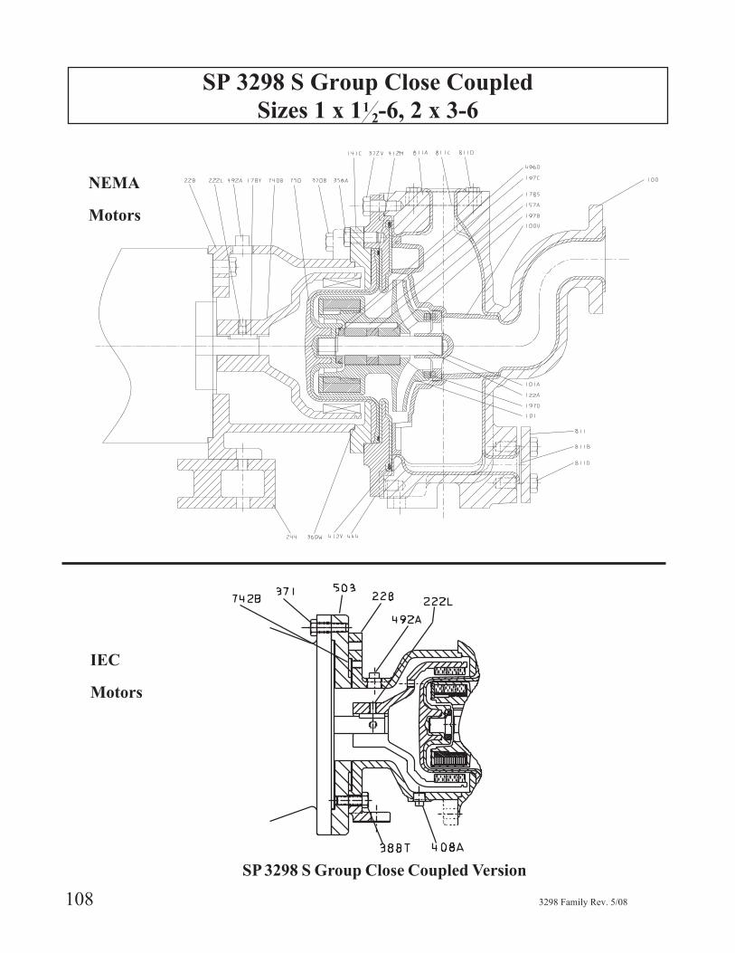
SP 3298 S Group Close Coupled
Sizes 1 x 112-6, 2 x 3-6
108 3298 Family Rev. 5/08
IEC
Motors
SP 3298 S Group Close Coupled Version
NEMA
Motors
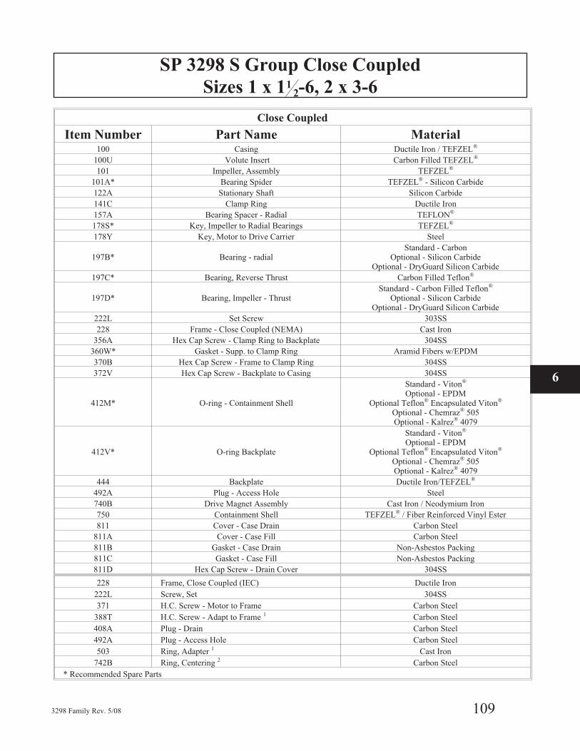
SP 3298 S Group Close Coupled
Sizes 1 x 112-6, 2 x 3-6
3298 Family Rev. 5/08 109
Close Coupled
Item Number Part Name Material100 Casing Ductile Iron / TEFZEL®
100U Volute Insert Carbon Filled TEFZEL®
101 Impeller, Assembly TEFZEL®
101A* Bearing Spider TEFZEL® - Silicon Carbide
122A Stationary Shaft Silicon Carbide
141C Clamp Ring Ductile Iron
157A Bearing Spacer - Radial TEFLON®
178S* Key, Impeller to Radial Bearings TEFZEL®
178Y Key, Motor to Drive Carrier Steel
197B* Bearing - radialStandard - Carbon
Optional - Silicon CarbideOptional - DryGuard Silicon Carbide
197C* Bearing, Reverse Thrust Carbon Filled Teflon®
197D* Bearing, Impeller - ThrustStandard - Carbon Filled Teflon®
Optional - Silicon CarbideOptional - DryGuard Silicon Carbide
222L Set Screw 303SS
228 Frame - Close Coupled (NEMA) Cast Iron
356A Hex Cap Screw - Clamp Ring to Backplate 304SS
360W* Gasket - Supp. to Clamp Ring Aramid Fibers w/EPDM
370B Hex Cap Screw - Frame to Clamp Ring 304SS
372V Hex Cap Screw - Backplate to Casing 304SS
412M* O-ring - Containment Shell
Standard - Viton®
Optional - EPDMOptional Teflon® Encapsulated Viton®
Optional - Chemraz® 505Optional - Kalrez® 4079
412V* O-ring Backplate
Standard - Viton®
Optional - EPDMOptional Teflon® Encapsulated Viton®
Optional - Chemraz® 505Optional - Kalrez® 4079
444 Backplate Ductile Iron/TEFZEL®
492A Plug - Access Hole Steel
740B Drive Magnet Assembly Cast Iron / Neodymium Iron
750 Containment Shell TEFZEL® / Fiber Reinforced Vinyl Ester
811 Cover - Case Drain Carbon Steel
811A Cover - Case Fill Carbon Steel
811B Gasket - Case Drain Non-Asbestos Packing
811C Gasket - Case Fill Non-Asbestos Packing
811D Hex Cap Screw - Drain Cover 304SS
228 Frame, Close Coupled (IEC) Ductile Iron
222L Screw, Set 304SS
371 H.C. Screw - Motor to Frame Carbon Steel
388T H.C. Screw - Adapt to Frame 1 Carbon Steel
408A Plug - Drain Carbon Steel
492A Plug - Access Hole Carbon Steel
503 Ring, Adapter 1 Cast Iron
742B Ring, Centering 2 Carbon Steel
* Recommended Spare Parts
6
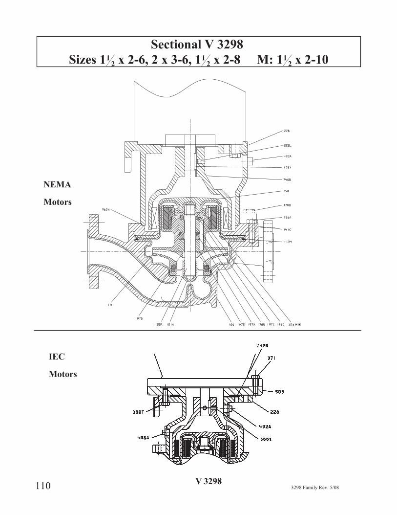
Sectional V 3298
Sizes 112 x 2-6, 2 x 3-6, 11
2 x 2-8 M: 112 x 2-10
110 3298 Family Rev. 5/08
IEC
Motors
V 3298
NEMA
Motors
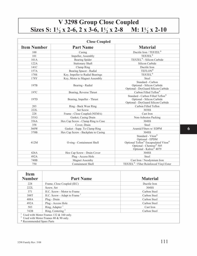
V 3298 Group Close Coupled
Sizes S: 112 x 2-6, 2 x 3-6, 11
2 x 2-8 M: 112 x 2-10
3298 Family Rev. 5/08 111
Close Coupled
Item Number Part Name Material100 Casing Ductile Iron / TEFZEL®
101 Impeller, Assembly TEFZEL®
101A Bearing Spider TEFZEL® - Silicon Carbide
122A Stationary Shaft Silicon Carbide
141C Clamp Ring Ductile Iron
157A Bearing Spacer - Radial TEFLON®
178S Key, Impeller to Radial Bearings TEFZEL®
178Y Key, Motor to Magnet Assembly Steel
197B Bearing - RadialStandard - Carbon
Optional - Silicon CarbideOptional - DryGuard Silicon Carbide
197C Bearing, Reverse Thrust Carbon Filled Teflon®
197D Bearing, Impeller - ThrustStandard - Carbon Filled Teflon®
Optional - Silicon CarbideOptional - DryGuard Silicon Carbide
203 Ring - Back Wear Ring Carbon Filled Teflon
222L Set Screw 303SS
228 Frame - Close Coupled (NEMA) Cast Iron
351G Gasket, Casing Drain Non-Asbestos Packing
356A Hex Cap Screw - Clamp Ring to Case 304SS
358 Cover, Drain Steel
360W Gasket - Supp. To Clamp Ring Aramid Fibers w/ EDPM
370B Hex Cap Screw - Backplate to Casing 304SS
412M O-ring - Containment Shell
Standard - Viton®
Optional - EPDMOptional Teflon® Encapsulated Viton®
Optional - Chemraz® 505Optional - Kalrez® 4079
426A Hex Cap Screw - Drain Cover 304SS
492A Plug - Access Hole Steel
740B Magnet Assemby Cast Iron / Neodymium Iron
750 Containment Shell TEFZEL® / Fiber Reinforced Vinyl Ester
ItemNumber Part Name Material
228 Frame, Close Coupled (IEC) Ductile Iron
222L Screw, Set 304SS
371 H.C. Screw - Motor to Frame Carbon Steel
388T H.C. Screw - Adapt to Frame 1 Carbon Steel
408A Plug - Drain Carbon Steel
492A Plug - Access Hole Carbon Steel
503 Ring, Adapter 1 Cast Iron
742B Ring, Centering 2 Carbon Steel1 Used with Motor Frames 132 & 160 only.2 Used with Motor Frames 80 & 90 only.* Recommended Spare Parts
6

112 3298 Family Rev. 5/08
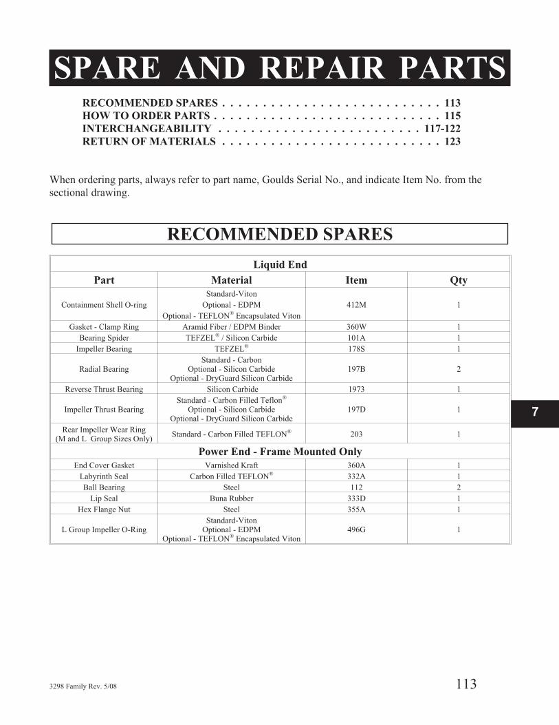
SPARE AND REPAIR PARTSRECOMMENDED SPARES . . . . . . . . . . . . . . . . . . . . . . . . . . . 113
HOW TO ORDER PARTS . . . . . . . . . . . . . . . . . . . . . . . . . . . . 115
INTERCHANGEABILITY . . . . . . . . . . . . . . . . . . . . . . . . . 117-122
RETURN OF MATERIALS . . . . . . . . . . . . . . . . . . . . . . . . . . . 123
When ordering parts, always refer to part name, Goulds Serial No., and indicate Item No. from the
sectional drawing.
RECOMMENDED SPARES
3298 Family Rev. 5/08 113
Liquid End
Part Material Item Qty
Containment Shell O-ring
Standard-Viton
412M 1Optional - EDPM
Optional - TEFLON® Encapsulated Viton
Gasket - Clamp Ring Aramid Fiber / EDPM Binder 360W 1
Bearing Spider TEFZEL® / Silicon Carbide 101A 1
Impeller Bearing TEFZEL® 178S 1
Radial BearingStandard - Carbon
Optional - Silicon CarbideOptional - DryGuard Silicon Carbide
197B 2
Reverse Thrust Bearing Silicon Carbide 1973 1
Impeller Thrust BearingStandard - Carbon Filled Teflon®
Optional - Silicon CarbideOptional - DryGuard Silicon Carbide
197D 1
Rear Impeller Wear Ring(M and L Group Sizes Only)
Standard - Carbon Filled TEFLON® 203 1
Power End - Frame Mounted Only
End Cover Gasket Varnished Kraft 360A 1
Labyrinth Seal Carbon Filled TEFLON® 332A 1
Ball Bearing Steel 112 2
Lip Seal Buna Rubber 333D 1
Hex Flange Nut Steel 355A 1
L Group Impeller O-RingStandard-Viton
Optional - EDPMOptional - TEFLON® Encapsulated Viton
496G 1
7
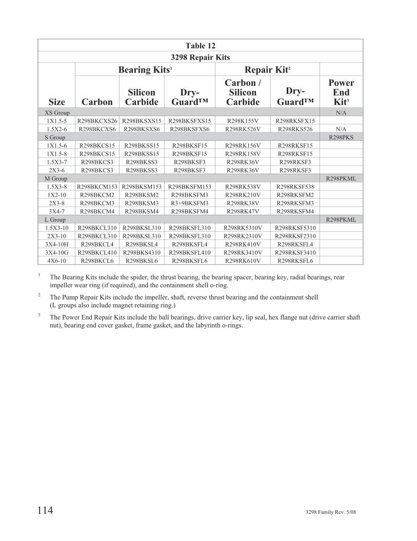
114 3298 Family Rev. 5/08
Table 12
3298 Repair Kits
Size
Bearing Kits1 Repair Kit2
CarbonSilicon
CarbideDry-
Guard™
Carbon /Silicon
Carbide
Dry-
Guard™
PowerEndKit3
XS Group N/A
1X1.5-5 R298BKCXS26 R298BKSXS15 R298BKSFXS15 R298K155V R298RKSFX15
1.5X2-6 R298BKCXS6 R298BKSXS6 R298BKSFXS6 R298RK526V R298RKS526 N/A
S Group R298PKS
1X1.5-6 R298BKCS15 R298BKSS15 R298BKSF15 R298RK156V R298RKSF15
1X1.5-8 R298BKCS15 R298BKSS15 R298BKSF15 R298RK158V R298RKSF15
1.5X3-7 R298BKCS3 R298BKSS3 R298BKSF3 R298RK36V R298RKSF3
2X3-6 R298BKCS3 R298BKSS3 R298BKSF3 R298RK36V R298RKSF3
M Group R298PKML
1.5X3-8 R298BKCM153 R298BKSM153 R298BKSFM153 R298RK538V R298RKSF538
1X2-10 R298BKCM2 R298BKSM2 R298BKSFM3 R298RK210V R298RKSFM2
2X3-8 R298BKCM3 R298BKSM3 R3+9BKSFM3 R298RK38V R298RKSFM3
3X4-7 R298BKCM4 R298BKSM4 R298BKSFM4 R298RK47V R298RKSFM4
L Group R298PKML
1.5X3-10 R298BKCL310 R298BKSL310 R298BKSFL310 R298RK5310V R298RKSF5310
2X3-10 R298BKCL310 R298BKSL310 R298BKSFL310 R298RK2310V R298RKSF2310
3X4-10H R298BKCL4 R298BKSL4 R298BKSFL4 R298RK410V R298RKSFL4
3X4-10G R298BKCL410 R298BKS4310 R298BKSFL410 R298RK3410V R298RKSF3410
4X6-10 R298BKCL6 R298BKSL6 R298BKSFL6 R298RK610V R298RKSFL6
1 The Bearing Kits include the spider, the thrust bearing, the bearing spacer, bearing key, radial bearings, rear
impeller wear ring (if required), and the containment shell o-ring.
2 The Pump Repair Kits include the impeller, shaft, reverse thrust bearing and the containment shell
(L groups also include magnet retaining ring.)
3 The Power End Repair Kits include the ball bearings, drive carrier key, lip seal, hex flange nut (drive carrier shaft
nut), bearing end cover gasket, frame gasket, and the labyrinth o-rings.

3298 Family Rev. 5/08 115
7
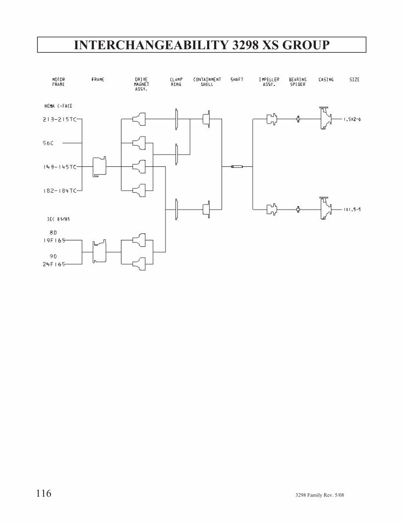
INTERCHANGEABILITY 3298 XS GROUP
116 3298 Family Rev. 5/08
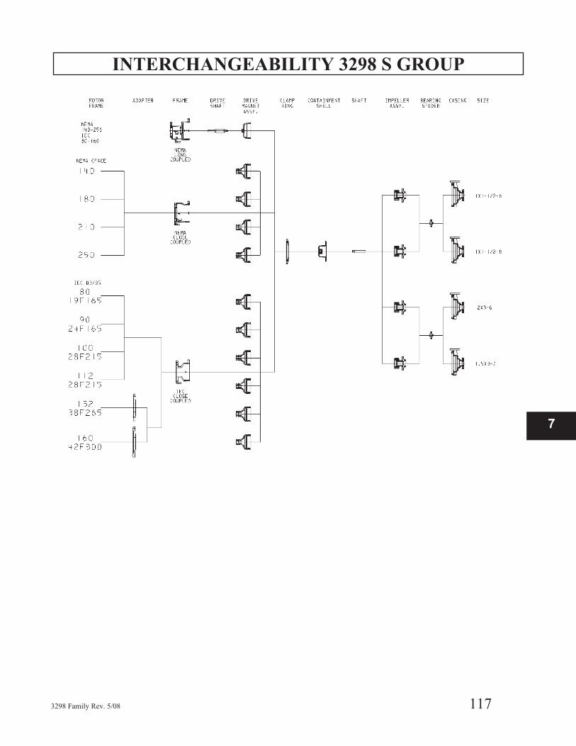
INTERCHANGEABILITY 3298 S GROUP
3298 Family Rev. 5/08 117
7
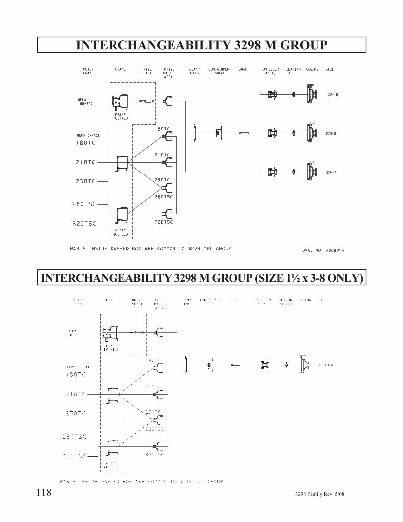
INTERCHANGEABILITY 3298 M GROUP
INTERCHANGEABILITY 3298 M GROUP (SIZE 1½ x 3-8 ONLY)
118 3298 Family Rev. 5/08
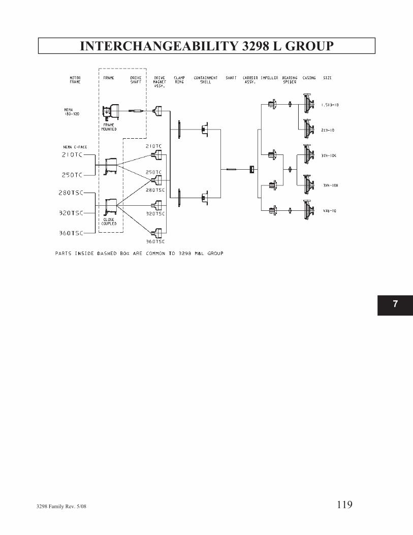
INTERCHANGEABILITY 3298 L GROUP
3298 Family Rev. 5/08 119
7
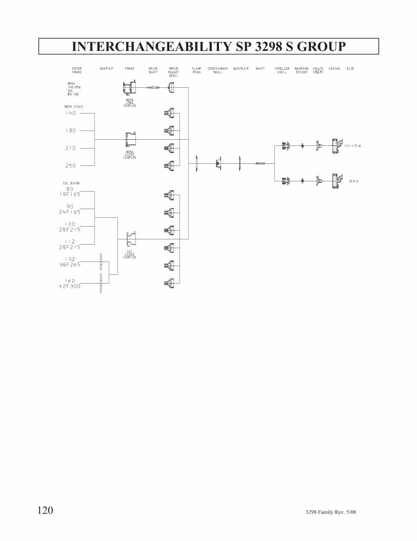
INTERCHANGEABILITY SP 3298 S GROUP
120 3298 Family Rev. 5/08
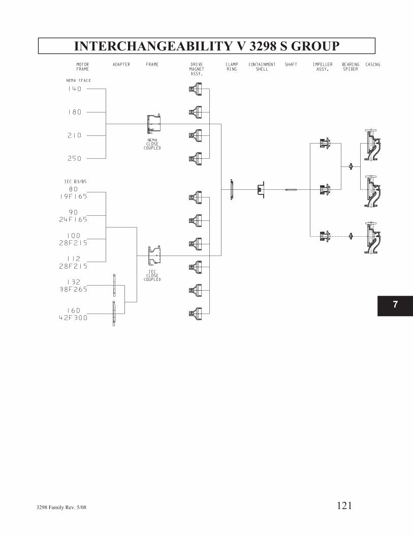
INTERCHANGEABILITY V 3298 S GROUP
3298 Family Rev. 5/08 121
7
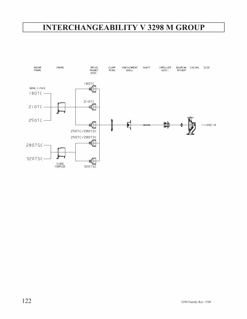
INTERCHANGEABILITY V 3298 M GROUP
122 3298 Family Rev. 5/08
RETURN OF MATERIALS
If it is necessary to return the pump to a Goulds factory orrepair facility for service, certain procedures must befollowed.
Do not return any parts without authorization from thewarranty engineer, a warranty claim number, and thepreprinted shipping label supplied by Goulds. In rareinstances because of the pumpage, ITT Goulds PumpsWarranty Services may, at their option, decide not to havethe parts returned.
The parts being returned must be decontaminated prior toshipment. The decontamination must be verified inwriting. The correct Material Safety Data Sheet (MSDS)must accompany the parts along with decontamination"sign off." This information is stated within the ITT
Goulds Pumps "decontamination procedure." TheWarranty Service engineer will send a copy of thisprocedure to the customer. Please remember thatinspection of the parts cannot be started until we receivethe proper documentation. This is a safety and legal issueand consequently strict adherence to procedure ismandatory — there will be no exceptions.
Before shipping, check with your carrier for specialprocedures that may be required when shipping highlymagnetic materials.
All pumps must be decontaminated prior to return. Referto Preparation for Disassembly and DecontaminationProcedure.
3298 Family Rev. 5/08 123
7

124 3298 Family Rev. 5/08
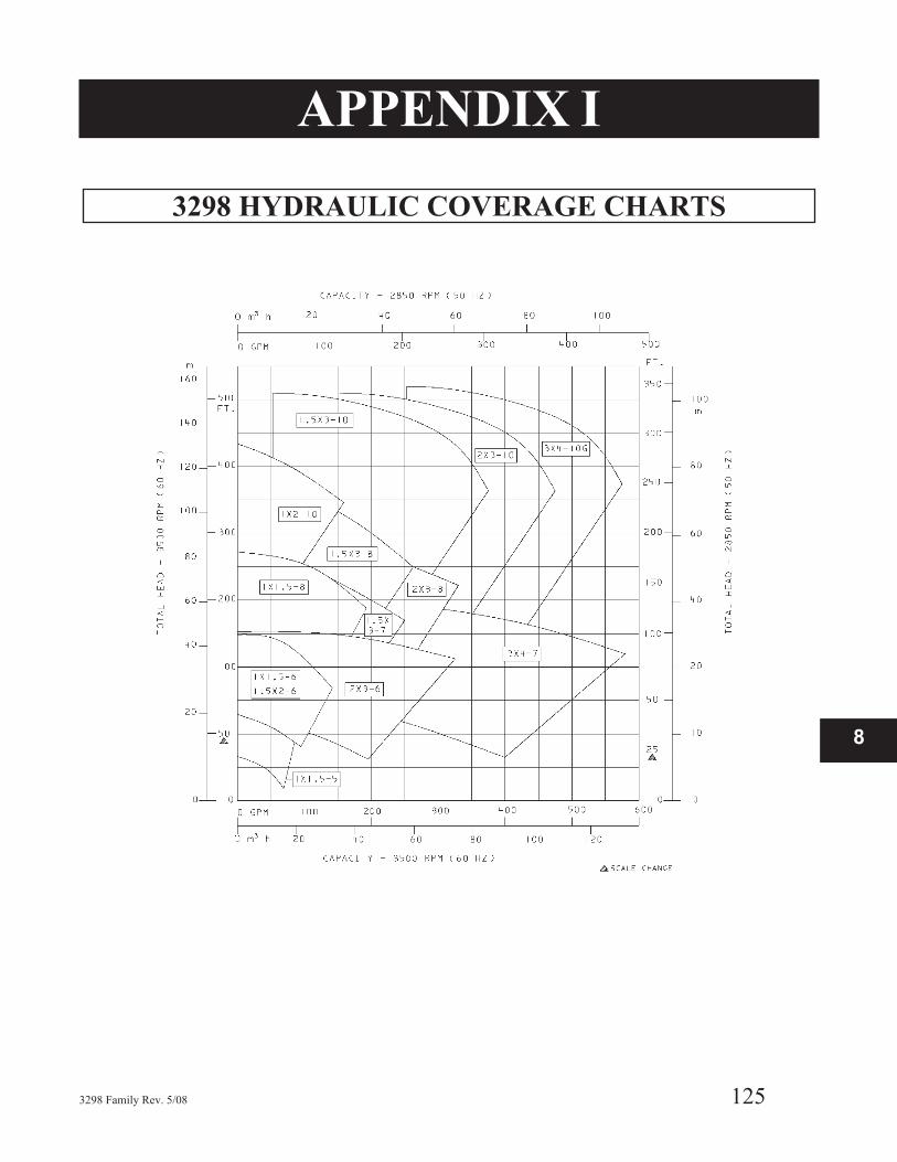
APPENDIX I
3298 HYDRAULIC COVERAGE CHARTS
3298 Family Rev. 5/08 125
8
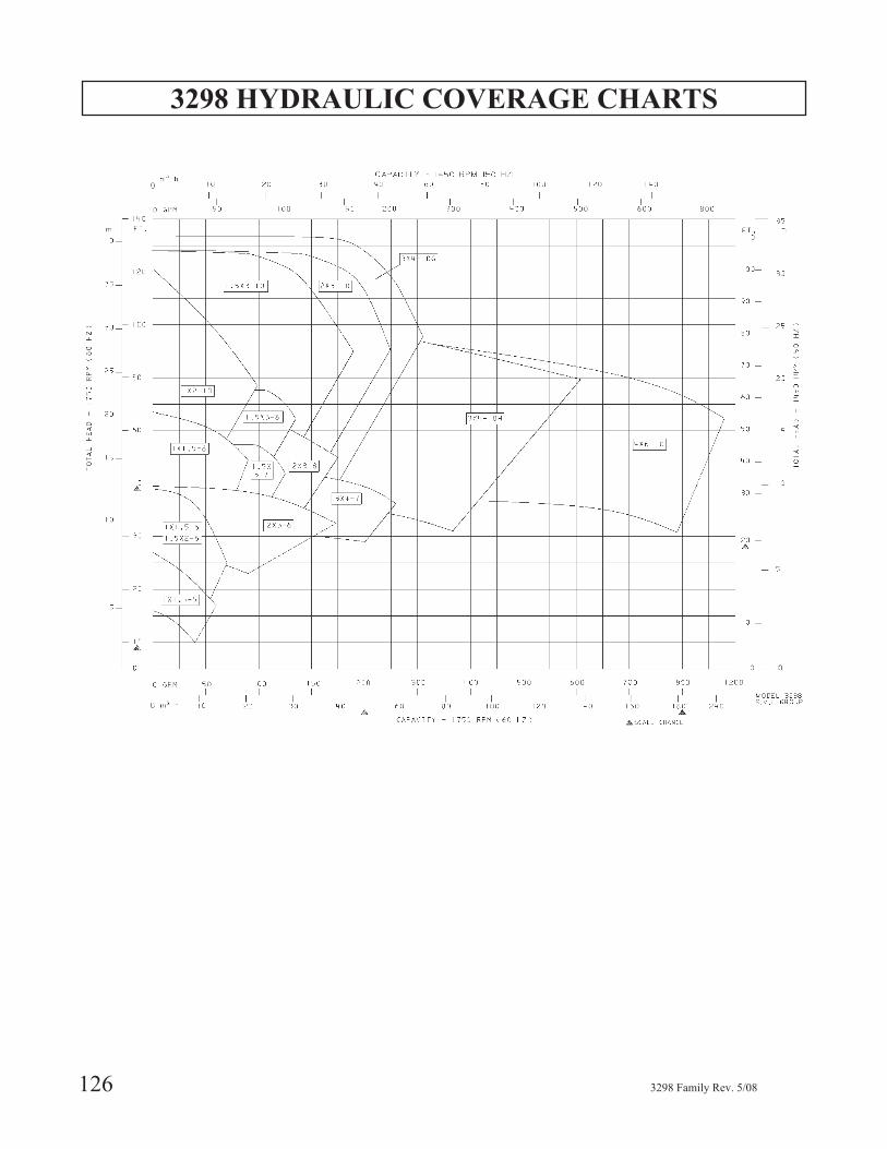
3298 HYDRAULIC COVERAGE CHARTS
126 3298 Family Rev. 5/08
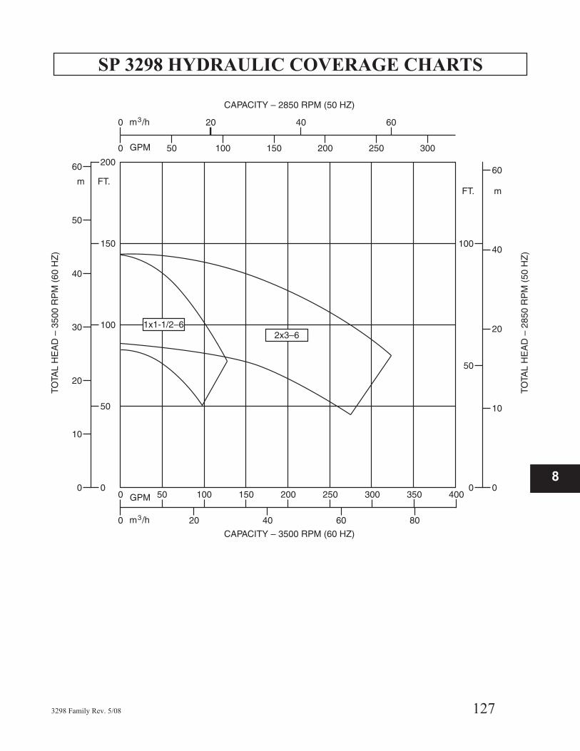
SP 3298 HYDRAULIC COVERAGE CHARTS
3298 Family Rev. 5/08 127
8
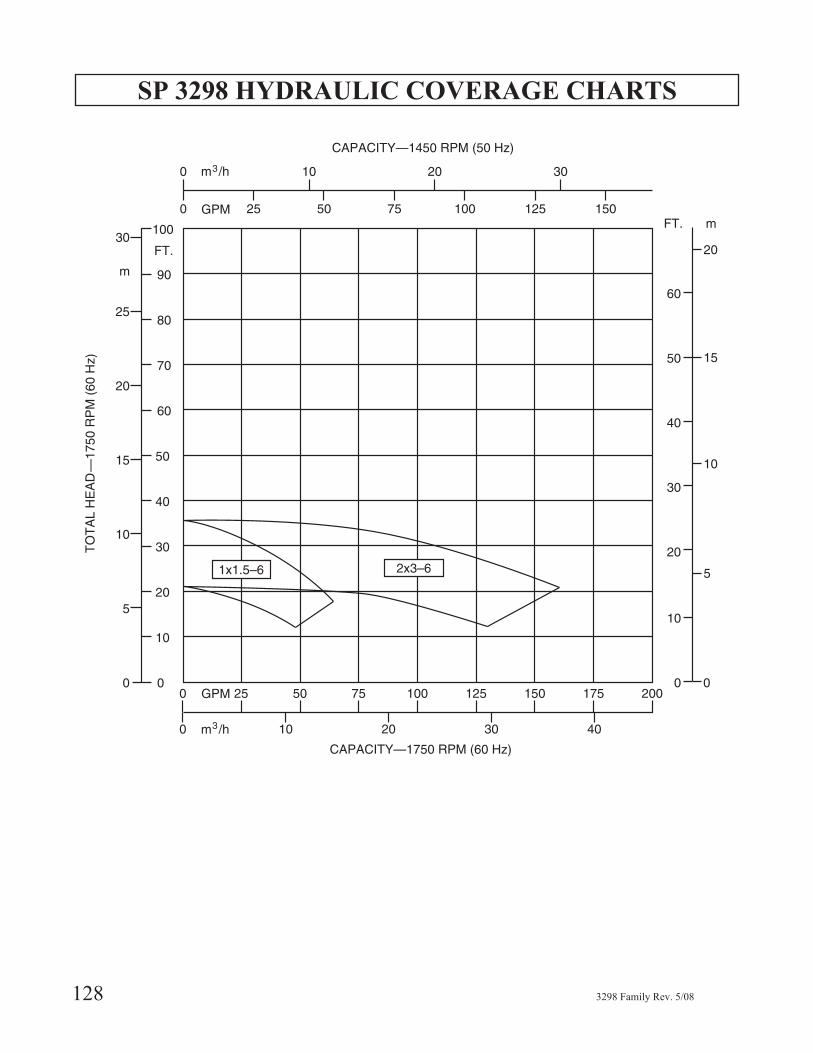
SP 3298 HYDRAULIC COVERAGE CHARTS
128 3298 Family Rev. 5/08
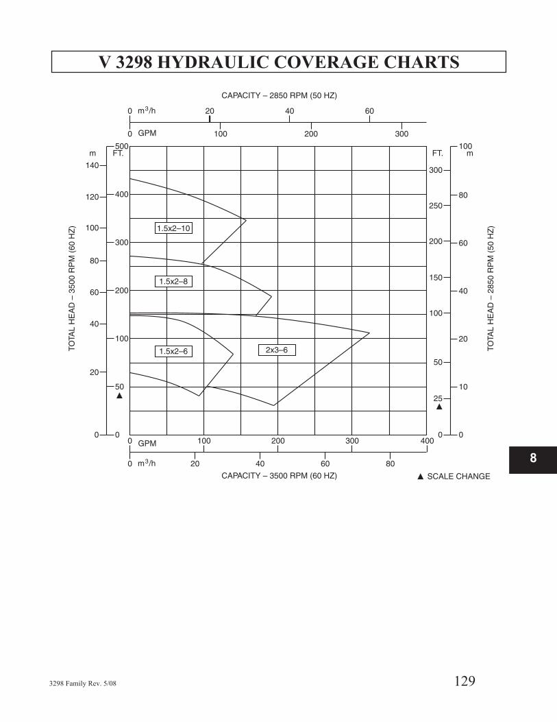
V 3298 HYDRAULIC COVERAGE CHARTS
3298 Family Rev. 5/08 129
8
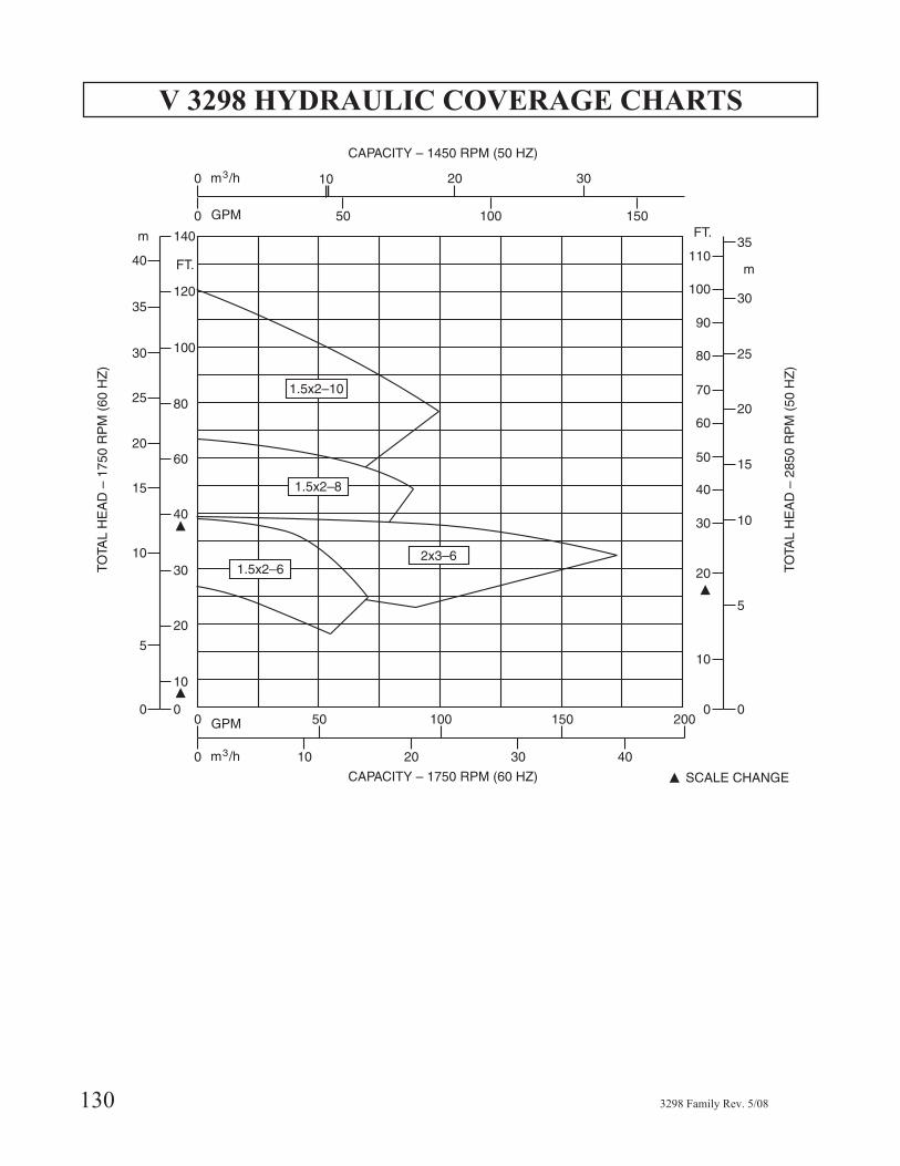
V 3298 HYDRAULIC COVERAGE CHARTS
130 3298 Family Rev. 5/08

APPENDIX II
COUPLING GUARD INSTALLATION -
Frame Mounted Only
� The coupling guard used in an ATEX classifiedenvironment must be constructed from a non-sparking material.
▲! WARNINGBefore assembly or disassembly of the coupling guard isperformed, the motor must be de- energized, the motorcontroller/starter put in a locked-out position, and acaution tag placed at the starter indicating the disconnect.Replace coupling guard before resuming normaloperation of the pump. Goulds Pumps assumes noliability for avoiding this practice.
Simplicity of design allows complete assembly of thecoupling guard, including the end plate (pump end), inabout fifteen minutes. If the end plate is already in place,assembly can be accomplished in about five minutes.
Assembly:
NOTE: If end plate (pump end) is already installed,make any necessary coupling adjustments and thenproceed to Step 2.
1. STX, MTX, LTX - Align end plate (pump end) to
the bearing frame. (No impeller adjustment
required.)
XLT-X Align the end plate (pump end) to the pump
bearing housing so that the large slots on the end
plate clear the bearing housing tap bolts and the small
slots are aligned to the impeller adjusting bolts.
Attach the end plate to the bearing housing using the
jam nuts on the impeller adjusting bolts as shown in
Fig. II-3.
After the end plate is attached to the bearing housing,
the impeller clearance must be checked and reset as
explained in the Preventive Maintenance section.
NOTE: Coupling adjustments should be completedbefore proceeding with coupling guard assembly.
3298 Family Rev. 5/08 131
8
Fig. II-1
Fig. II-2
Fig. II-3
B
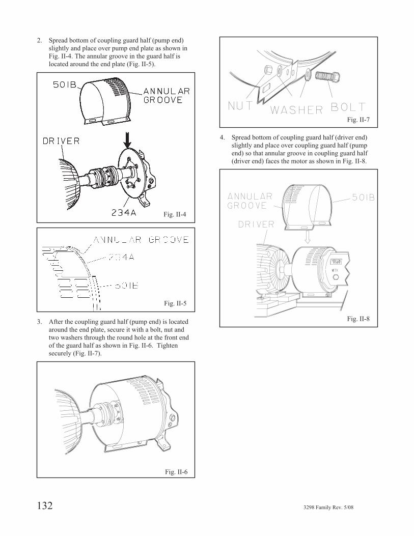
2. Spread bottom of coupling guard half (pump end)
slightly and place over pump end plate as shown in
Fig. II-4. The annular groove in the guard half is
located around the end plate (Fig. II-5).
3. After the coupling guard half (pump end) is located
around the end plate, secure it with a bolt, nut and
two washers through the round hole at the front end
of the guard half as shown in Fig. II-6. Tighten
securely (Fig. II-7).
4. Spread bottom of coupling guard half (driver end)
slightly and place over coupling guard half (pump
end) so that annular groove in coupling guard half
(driver end) faces the motor as shown in Fig. II-8.
132 3298 Family Rev. 5/08
Fig. II-4
Fig. II-5
Fig. II-6
Fig. II-7
Fig. II-8
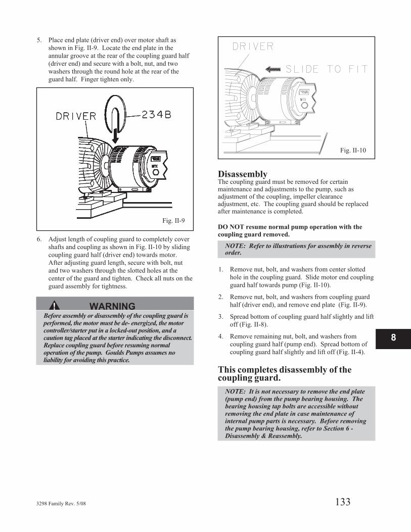
5. Place end plate (driver end) over motor shaft as
shown in Fig. II-9. Locate the end plate in the
annular groove at the rear of the coupling guard half
(driver end) and secure with a bolt, nut, and two
washers through the round hole at the rear of the
guard half. Finger tighten only.
6. Adjust length of coupling guard to completely cover
shafts and coupling as shown in Fig. II-10 by sliding
coupling guard half (driver end) towards motor.
After adjusting guard length, secure with bolt, nut
and two washers through the slotted holes at the
center of the guard and tighten. Check all nuts on the
guard assembly for tightness.
▲! WARNINGBefore assembly or disassembly of the coupling guard isperformed, the motor must be de- energized, the motorcontroller/starter put in a locked-out position, and acaution tag placed at the starter indicating the disconnect.Replace coupling guard before resuming normaloperation of the pump. Goulds Pumps assumes noliability for avoiding this practice.
DisassemblyThe coupling guard must be removed for certainmaintenance and adjustments to the pump, such asadjustment of the coupling, impeller clearanceadjustment, etc. The coupling guard should be replacedafter maintenance is completed.
DO NOT resume normal pump operation with the
coupling guard removed.
NOTE: Refer to illustrations for assembly in reverseorder.
1. Remove nut, bolt, and washers from center slotted
hole in the coupling guard. Slide motor end coupling
guard half towards pump (Fig. II-10).
2. Remove nut, bolt, and washers from coupling guard
half (driver end), and remove end plate (Fig. II-9).
3. Spread bottom of coupling guard half slightly and lift
off (Fig. II-8).
4. Remove remaining nut, bolt, and washers from
coupling guard half (pump end). Spread bottom of
coupling guard half slightly and lift off (Fig. II-4).
This completes disassembly of thecoupling guard.
NOTE: It is not necessary to remove the end plate(pump end) from the pump bearing housing. Thebearing housing tap bolts are accessible withoutremoving the end plate in case maintenance ofinternal pump parts is necessary. Before removingthe pump bearing housing, refer to Section 6 -Disassembly & Reassembly.
3298 Family Rev. 5/08 133
8
Fig. II-9
Fig. II-10

134 3298 Family Rev. 5/08
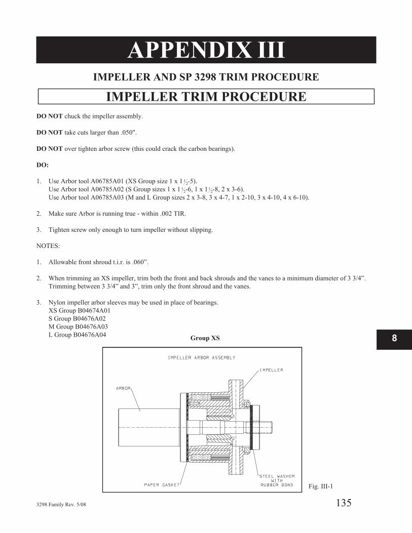
APPENDIX IIIIMPELLER AND SP 3298 TRIM PROCEDURE
IMPELLER TRIM PROCEDURE
DO NOT chuck the impeller assembly.
DO NOT take cuts larger than .050".
DO NOT over tighten arbor screw (this could crack the carbon bearings).
DO:
1. Use Arbor tool A06785A01 (XS Group size 1 x 1 12-5).
Use Arbor tool A06785A02 (S Group sizes 1 x 1 12-6, 1 x 11
2-8, 2 x 3-6).
Use Arbor tool A06785A03 (M and L Group sizes 2 x 3-8, 3 x 4-7, 1 x 2-10, 3 x 4-10, 4 x 6-10).
2. Make sure Arbor is running true - within .002 TIR.
3. Tighten screw only enough to turn impeller without slipping.
NOTES:
1. Allowable front shroud t.i.r. is .060”.
2. When trimming an XS impeller, trim both the front and back shrouds and the vanes to a minimum diameter of 3 3/4”.
Trimming between 3 3/4” and 3”, trim only the front shroud and the vanes.
3. Nylon impeller arbor sleeves may be used in place of bearings.
XS Group B04674A01
S Group B04676A02
M Group B04676A03
L Group B04676A04
3298 Family Rev. 5/08 135
8Group XS
Fig. III-1
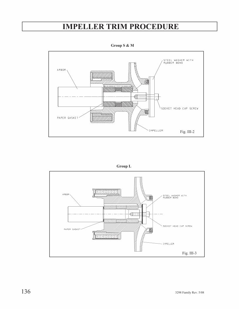
IMPELLER TRIM PROCEDURE
136 3298 Family Rev. 5/08
Fig. III-2
Group S & M
Fig. III-3
Group L
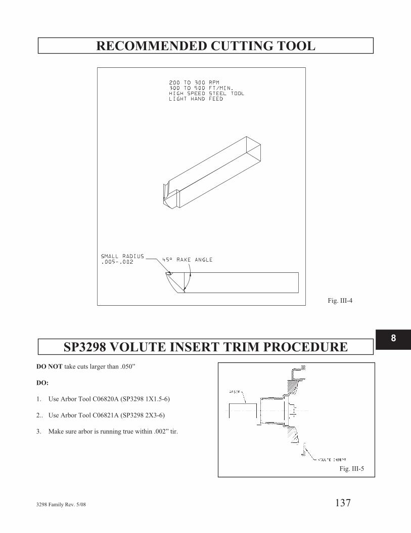
RECOMMENDED CUTTING TOOL
SP3298 VOLUTE INSERT TRIM PROCEDURE
DO NOT take cuts larger than .050”
DO:
1. Use Arbor Tool C06820A (SP3298 1X1.5-6)
2.. Use Arbor Tool C06821A (SP3298 2X3-6)
3. Make sure arbor is running true within .002” tir.
3298 Family Rev. 5/08 137
8
Fig. III-5
Fig. III-4
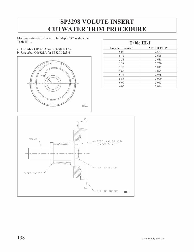
SP3298 VOLUTE INSERT
CUTWATER TRIM PROCEDURE
Machine cutwater diameter to full depth "R" as shown inTable III-1.
a. Use arbor C06820A for SP3298 1x1.5-6b. Use arbor C06821A for SP3298 2x3-6
Table III-1Impeller Diameter "R" +/0 0/010"
5.00 2.563
5.12 2.625
5.25 2.688
5.38 2.750
5.50 2.813
5.62 2.875
5.75 2.938
5.88 3.000
6.00 3.063
6.06 3.094
138 3298 Family Rev. 5/08
III-6
III-7
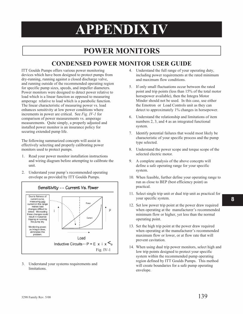
APPENDIX IV
POWER MONITORS
CONDENSED POWER MONITOR USER GUIDEITT Goulds Pumps offers various power monitoringdevices which have been designed to protect pumps fromdry-running, running against a closed discharge valve,and running outside of the recommended operating regionfor specific pump sizes, speeds, and impeller diameters.Power monitors were designed to detect power relative toload which is a linear function as opposed to measuringamperage relative to load which is a parabolic function.The linear characteristic of measuring power vs. loadenhances sensitivity at low power conditions whereincrements in power are critical. See Fig. IV-1 forcomparison of power measurements vs. amperagemeasurements. Quite simply, a properly adjusted andinstalled power monitor is an insurance policy forsecuring extended pump life.
The following summarized concepts will assist ineffectively selecting and properly calibrating powermonitors used to protect pumps.
1. Read your power monitor installation instructions
and wiring diagram before attempting to calibrate the
unit.
2. Understand your pump’s recommended operating
envelope as provided by ITT Goulds Pumps.
3. Understand your systems requirements and
limitations.
4. Understand the full range of your operating duty,
including power requirements at the rated minimum
and maximum flow conditions.
5. If only small fluctuations occur between the rated
point and trip points (less than 15% of the total motor
horsepower available), then the Integra Motor
Minder should not be used. In this case, use either
the Emotron or Load Controls unit as they can
detect to approximately 1% changes in horsepower.
6. Understand the relationship and limitations of item
numbers 2, 3, and 4 as an integrated functional
system.
7. Identify potential failures that would most likely be
characteristic of your specific process and the pump
type selected.
8. Understand the power scope and torque scope of the
selected electric motor.
9. A complete analysis of the above concepts will
define a safe operating range for your specific
system.
10. When feasible, further define your operating range to
run as close to BEP (best efficiency point) as
practical.
11. Select single trip unit or dual trip unit as practical for
your specific system.
12. Set low power trip point at the power draw required
when operating at the manufacturer’s recommended
minimum flow or higher, yet less than the normal
operating point.
13. Set the high trip point at the power draw required
when operating at the manufacturer’s recommended
maximum flow or lower, or at flow rate that will
prevent cavitation.
14. When using dual trip power monitors, select high and
low trip points designed to protect your specific
system within the recommended pump operating
region defined by ITT Goulds Pumps. This method
will create boundaries for a safe pump operating
envelope.
3298 Family Rev. 5/08 139
8
Fig. IV-1
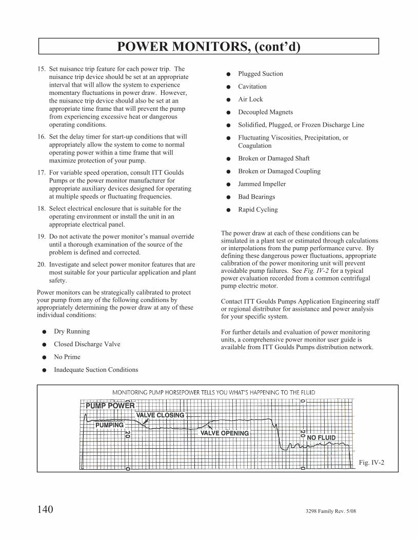
POWER MONITORS, (cont’d)
15. Set nuisance trip feature for each power trip. The
nuisance trip device should be set at an appropriate
interval that will allow the system to experience
momentary fluctuations in power draw. However,
the nuisance trip device should also be set at an
appropriate time frame that will prevent the pump
from experiencing excessive heat or dangerous
operating conditions.
16. Set the delay timer for start-up conditions that will
appropriately allow the system to come to normal
operating power within a time frame that will
maximize protection of your pump.
17. For variable speed operation, consult ITT Goulds
Pumps or the power monitor manufacturer for
appropriate auxiliary devices designed for operating
at multiple speeds or fluctuating frequencies.
18. Select electrical enclosure that is suitable for the
operating environment or install the unit in an
appropriate electrical panel.
19. Do not activate the power monitor’s manual override
until a thorough examination of the source of the
problem is defined and corrected.
20. Investigate and select power monitor features that are
most suitable for your particular application and plant
safety.
Power monitors can be strategically calibrated to protectyour pump from any of the following conditions byappropriately determining the power draw at any of theseindividual conditions:
� Dry Running
� Closed Discharge Valve
� No Prime
� Inadequate Suction Conditions
� Plugged Suction
� Cavitation
� Air Lock
� Decoupled Magnets
� Solidified, Plugged, or Frozen Discharge Line
� Fluctuating Viscosities, Precipitation, or
Coagulation
� Broken or Damaged Shaft
� Broken or Damaged Coupling
� Jammed Impeller
� Bad Bearings
� Rapid Cycling
The power draw at each of these conditions can besimulated in a plant test or estimated through calculationsor interpolations from the pump performance curve. Bydefining these dangerous power fluctuations, appropriatecalibration of the power monitoring unit will preventavoidable pump failures. See Fig. IV-2 for a typicalpower evaluation recorded from a common centrifugalpump electric motor.
Contact ITT Goulds Pumps Application Engineering staffor regional distributor for assistance and power analysisfor your specific system.
For further details and evaluation of power monitoringunits, a comprehensive power monitor user guide isavailable from ITT Goulds Pumps distribution network.
140 3298 Family Rev. 5/08
Fig. IV-2
APPENDIX V
Reliability Tips for Operating
Lined Magnetically-Driven Sealless Pumps
QUICK REFERENCE SUMMARY
These summarized reliability guidelines outlinerecommendations for creating an optimal environment foroperating lined mag-drive pumps. For further details onthe subject of operating a lined-mag drive pump withsuperior reliability, please request the Lined Mag-DriveReliability Guide from your ITT Goulds Pumps’representative.
� Do not operate mag-drive pumps under no flow
conditions.
� Do not operate mag-drive pumps against a closed
discharge valve.
� Do not operate mag-drive pumps with solids that
exceed the manufacturer’s maximum limits in particle
size or concentration.
� Before operating mag-drive pumps, confirm chemical
compatibility of process liquid with all wetted pump
components in an effort to reduce corrosion,
permeation, or erosion.
� Do not operate mag-drive pumps with process liquids
that may exceed the maximum temperature limits or
fall below the minimum temperature limits defined by
the pump manufacturer.
� Do not operate mag-drive pumps outside of the
manufacturer’s recommended operating range.
Otherwise, recirculate adequate flow through bypass
lines when operating near or below the manufacturer’s
recommended mechanical and thermal operating flow
to prevent excessive temperature rise or recirculation
cavitation.
� Consider the inner and outer magnet assemblies’
material temperature limits and recoverable flux
density losses due to increased temperatures.
� Do not operate mag-drive pump without considering
the process liquid’s vapor pressure characteristics over
the temperature range of the application. Adequate
NPSHa as well as vapor pressure is mandatory to
prevent cavitation or vaporization in localized low
pressure regions within the pump.
� Use power monitoring devices when potentially
operating near or outside of the manufacturer’s
recommended operating envelope.
� Consider temperature controlling devices such as heat
jackets or steam tracing for pumps that are subject to
process fluids that transform characteristics such as
viscosity, specific gravity, crystallization, coagulation,
solidification, or vaporization with variable process
temperatures.
� Use temperature monitoring devices such as
thermocouples, RTDs, temperature controllers, or
thermometers when process fluid is susceptible to
critical variations in temperature.
� Use leak detectors such as fiber optic sensing devices
or pressure monitoring devices when fluid is prohibited
from entering the atmosphere.
� Ensure selected motor torque at maximum power and
start-up conditions for corrected hydraulic and
magnetic loss power at worst case fluid specific gravity
and viscosity is less than the magnet break-away torque
at maximum temperature.
� Keep process liquid in liquid form. Prevent the liquid
from flashing.
� Do not exceed the manufacturer’s maximum viscosity
limits as internal fluid circulation velocities will be
inadequate to properly cool and lubricate sleeve
bearings.
3298 Family Rev. 5/08 141
8

142 3298 Family Rev. 5/08

APPENDIX VI
Polyshield® ANSI Combo
Installation, Operation, and Maintenance Instructions
SAFETY CONSIDERATIONSSeveral important general precautions are listed below:
1. Do not remove the Polyshield® ANSI Combo from its
shipping pallet until you are ready to hoist it onto its
location.
2. Do not subject the Polyshield® ANSI or Custom
Combo to rough handling or unnecessary mechanical
shock.
3. Do not attempt to lift the Polyshield® ANSI Combo
by any means other than that which is prescribed in
these procedures.
4. Do not use hammer blows or other impact loading to
adjust the positioning of the Polyshield® ANSI
Combo. Do not pry against the Polyshield® mounting
block when moving the motor during shaft alignment.
5. Do not attempt to transport, handle, or install a
Polyshield® ANSI Combo when ambient temperature
is below -50° F (-45° C).
6. Do not operate a pump installed on a Polyshield® ANSI
Combo at process fluid temperatures in excess of 300° F
(150° C) with polymer mounting pads and 500° F with
alloy mounting pads unless prior approval from ITT
Industries - Goulds Pumps is obtained in writing.
� Service temperature in an ATEX classifiedenvironment is limited by Table 1 in the SafetySection.
NOTE: Always coordinate installation activity withoperations personnel, and follow all plant safetyrequirements and applicable safety and health laws,directives and regulations.
OVERVIEW
� CAUTION
Observance of proper handling procedures duringinstallation is extremely important to prevent damageto the Polyshield
®ANSI Combo. While polymer
concrete possesses inherent high strength, subjecting itto impact or bending loads through rough handling orimproper lifting or mounting may result in irreparabledamage to the Polyshield
®ANSI Combo as well as
damage to the mounted equipment or injury topersonnel.
APPLICATIONThe polymer concrete material used in the manufacture ofthe Polyshield® ANSI Combo has been formulated forapplication in a wide range of corrosive fluid handlingservices. The material is not, however, universallycorrosion resistant. A comprehensive corrosion guide isavailable. (Refer to Accessories Section of the ElectronicPricebook.) It is strongly recommended that this bulletinbe reviewed prior to specifying or installing a Polyshield®
Product.
The Polyshield® ANSI Combo is also suitable forapplication in a wide range of fluid process temperatures,specifically, -50° F to 300° F (-45° C to 150° C).Depending on the configuration of the pump that is to bemounted on the Polyshield®, fluid process temperature inexcess of 300° F (150° C) may be permissible. Contactyour ITT Industries - Goulds Pumps representative forassistance in determining acceptability of a specificapplication.
STORAGEThis section addresses the storage procedures for thePolyshield® ANSI Combo only. When storingPolyshield® ANSI Combos and pump assemblies, it isimportant that the proper storage procedures for the pumpbe observed as well. Refer to the Installation, Operationand Maintenance Instructions (IOM) for the particularGoulds pump that is mounted on your Polyshield®
product.
Polyshield® normal packaging is designed to protect thePolyshield® ANSI Combo during shipment and handlingfrom the time it is manufactured at the factory toinstallation at the end user’s job site. If the Polyshield®
Combo is to be stored for a period of time prior toinstallation, it is recommended that the followingprocedures be followed:
a. Leave the Polyshield® ANSI Combo strapped to its
wooden shipping pallet.
b. Place the pallet on a solid, dry, level surface in a
location where the ANSI Combo cannot be struck by
passing fork trucks, falling objects, etc. Make sure
the pallet does not rock.
c. Do not stack heavy objects on top of the Polyshield®
ANSI Combo.
d. If the Polyshield® ANSI Combo is to be stored in an
3298 Family Rev. 5/08 143
8
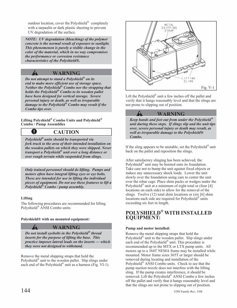
outdoor location, cover the Polyshield® completely
with a tarpaulin or dark plastic sheeting to prevent
UV degradation of the surface.
NOTE: UV degradation (bleaching) of the polymerconcrete is the normal result of exposure to sunlight.This phenomenon is purely a visible change in thecolor of the material, which in no way compromisesthe performance or corrosion resistancecharacteristics of the Polyshield®.
▲! WARNINGDo not attempt to stand a Polyshield
®on its
end to make more efficient use of storage space.Neither the Polyshield
®Combo nor the strapping that
holds the Polyshield®
Combo to its wooden pallethave been designed for vertical storage. Severepersonal injury or death, as well as irreparabledamage to the Polyshield
®Combo may result if the
Combo tips over.
Lifting Polyshield®
Combo Units and Polyshield®
Combo / Pump Assemblies
� CAUTION
Polyshield®
units should be transported viafork truck to the area of their intended installation onthe wooden pallets on which they were shipped. Nevertransport a Polyshield
®unit over a long distance or
over rough terrain while suspended from slings.
Only trained personnel should do lifting. Pumps andmotors often have integral lifting eyes or eye bolts.These are intended for use in lifting the individualpieces of equipment. Do not use these features to lift aPolyshield
®Combo / pump assembly.
Lifting
The following procedures are recommended for liftingPolyshield® ANSI Combo units:
Polyshield® with no mounted equipment:
▲! WARNINGDo not install eyebolts in the Polyshield
®thread
inserts for the purpose of lifting the base. Thispractice imposes lateral loads on the inserts — whichthey were not designed to withstand.
Remove the metal shipping straps that hold thePolyshield® unit to the wooden pallet. Slip slings undereach end of the Polyshield® unit as a harness (Fig. VI-1).
Lift the Polyshield® unit a few inches off the pallet andverify that it hangs reasonably level and that the slings arenot prone to slipping out of position.
▲! WARNINGKeep hands and feet out from under the Polyshield
®
unit during these steps. If slings slip and the unit tipsover, severe personal injury or death may result, aswell as irreparable damage to the Polyshield®Combo.
If the sling appears to be unstable, set the Polyshield® unitback on the pallet and reposition the slings.
After satisfactory slinging has been achieved, thePolyshield® unit may be hoisted onto its foundation.Take care not to bump the unit against fixed objects orinduce any unnecessary shock loads. Lower the unitslowly over the foundation using care to center the unitover the rebar cage. Place shim packs or wedges under thePolyshield® unit at a minimum of eight total or (four [4]locations on each side) to allow for the removal of theslings. Twelve (12) total shim locations or (six [6] shimlocations each side are required for Polyshield® unitsexceeding six feet in length.
POLYSHIELD®
WITH INSTALLEDEQUIPMENT:
Pump and motor installed:
Remove the metal shipping straps that hold thePolyshield® unit to the wooden pallet. Slip slings undereach end of the Polyshield® unit. This procedure isrecommended up to the MTX or LTX pump units. Allmotors up to a 364T NEMA frame may be installed whilemounted. Motor frame sizes 365T or larger should beremoved during locating and installation of thePolyshield® ANSI Combo units. Check to see that thepump suction nozzle does not interfere with the liftingsling. If the pump creates interference, it should beremoved. Lift the Polyshield® ANSI Combo a few inchesoff the pallet and verify that it hangs reasonably level andthat the slings are not prone to slipping out of position.
144 3298 Family Rev. 5/08
Fig. V-1
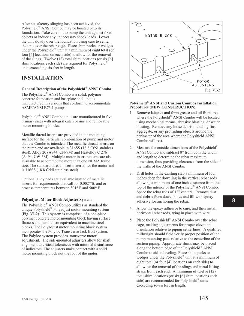
After satisfactory slinging has been achieved, thePolyshield® ANSI Combo may be hoisted onto itsfoundation. Take care not to bump the unit against fixedobjects or induce any unnecessary shock loads. Lowerthe unit slowly over the foundation using care to centerthe unit over the rebar cage. Place shim packs or wedgesunder the Polyshield® unit at a minimum of eight total (orfour [4] locations on each side) to allow for the removalof the slings. Twelve (12) total shim locations (or six [6]shim locations each side) are required for Polyshield®
units exceeding six feet in length.
INSTALLATION
General Description of the Polyshield®
ANSI Combo
The Polyshield® ANSI Combo is a solid, polymerconcrete foundation and baseplate shell that ismanufactured in versions that conform to accommodateASME/ANSI B73.1 pumps.
Polyshield® ANSI Combo units are manufactured in fiveprimary sizes with integral catch basins and removablemotor mounting blocks.
Metallic thread inserts are provided in the mountingsurface for the particular combination of pump and motorthat the Combo is intended. The metallic thread inserts onthe pump end are available in 316SS (18.8 CrNi stainlesssteel), Alloy 20 (A744, CN-7M) and Hastelloy C 276(A494, CW-6M). Multiple motor insert patterns are alsoavailable to accommodate more than one NEMA framesize. The standard thread insert material for the motor endis 316SS (18.8 CrNi stainless steel).
Optional alloy pads are available instead of metallicinserts for requirements that call for 0.002”/ft. and orprocess temperatures between 301° F and 500° F.
Polyadjust Motor Block Adjuster System
The Polyshield® ANSI Combo utilizes as standard theunique Polyshield® Polyadjust motor mounting system(Fig. VI-2). This system is comprised of a one-piecepolymer concrete motor mounting block having surfaceflatness and parallelism equivalent to machine steelblocks. The Polyadjust motor mounting block systemincorporates the Polyloc Transverse Jack Bolt system.The Polyloc system provides transverse motoradjustment. The side-mounted adjusters allow for shaftalignment to critical tolerances with minimal disturbanceof indicators. The adjusters make contact with a solidmotor mounting block not the foot of the motor.
Polyshield®
ANSI and Custom Combos InstallationProcedures (NEW CONSTRUCTION)
1. Remove laitance and form grease and oil from area
where the Polyshield® ANSI Combo will be located
using mechanical means, abrasive blasting, or water
blasting. Remove any loose debris including fins,
aggregate, or any protruding objects around the
perimeter of the area where the Polyshield ANSI
Combo will rest.
2. Measure the outside dimensions of the Polyshield®
ANSI Combo and subtract 8” from both the width
and length to determine the rebar maximum
dimension, thus providing clearance from the side of
the walls of the ANSI Combo.
3. Drill holes in the existing slab a minimum of four
inches deep for doweling in the vertical rebar rods
allowing a minimum of one inch clearance from the
top of the interior of the Polyshield® ANSI Combo.
Space the rebar rods of 12” centers. Remove dust
and debris from dowel holes and fill with epoxy
adhesive for anchoring the rebar.
4. Allow the epoxy adhesive to cure, and then install
horizontal rebar rods, tying in place with wire.
5. Place the Polyshield® ANSI Combo over the rebar
cage, making adjustments for proper elevation,
orientation relative to piping centerlines. A qualified
millwright should field verify proper position of the
pump mounting pads relative to the centerline of the
suction piping. Appropriate shims may be placed
along the bottom edge of the Polyshield® ANSI
Combo to aid in leveling. Place shim packs or
wedges under the Polyshield® unit at a minimum of
eight total (or four [4] locations on each side) to
allow for the removal of the slings and metal lifting
straps from each end. A minimum of twelve (12)
total shim locations (or six [6] shim locations each
side) are recommended for Polyshield® units
exceeding seven feet in length.
3298 Family Rev. 5/08 145
8
Fig. VI-2
6. Check and verify the dimensions again before the
grouting procedure begins.
7. A low slump standard concrete mix is suitable for
filling the Polyshield® ANSI Combo in new
construction.
8. Seal around the outside bottom perimeter of the
Polyshield® ANSI Combo with a fast setting
hydraulic cement. Two brand name hydraulic
cements are: Water Plug Hydraulic Cement and
Dam-It Non Shrink Hydraulic Cement.
9. Pour the concrete mixture through the grout fill port
on the top of the Polyshield® ANSI Combo using a
concrete vibrator to ensure proper flow of the
concrete. Do not over vibrate as excessive vibrating
leads to larger aggregate settling which will result in
a weak mix.
10. Pour the concrete to the bottom edge of the grout fill
port.
11. Remove any loose debris from around edges of the
grout fill port.
12. Seal grout fill port with grout port plug and
Polyshield® Seal Kit provided.
13. Install pump, motor, and attach lines.
TOOLS FOR INSTALLATION
� Hammer drill with proper size bit
� Worm gear saw with diamond blade (if required)
� Rebar cutters (new installation)
� Concrete mixer
� Concrete vibrator
� Lifting device (for placing Polyshield®
Foundation)
� Hand tools
� Chipping hammer
� Pressure washer or abrasive blast rig as required
� Epoxy adhesive (for setting rebar into concrete slab
– new installation)
� Rebar tie wire
� Fast set cement
POLYSHIELD®
ANSI COMBOSEALING KIT EPOXY NOVOLAC(EN) INSTRUCTIONS
Each Kit contains:
� Polyshield® EN Resin
� Polyshield® EN Hardener
� Stir Sticks
� Latex Gloves
� Instruction Sheet
� MSDS Material Safety Data Sheet
APPLICATION INSTRUCTIONS:The Polyshield® EN Sealing Kit is intended for use in (1)bonding the plug into the grout hole at the top of thecombo and (2) sealing and providing chemical resistancebarrier around the perimeter of the pump pad.
1. All surfaces to be bonded should be thoroughly
cleaned and should be free of dust, oils and
contaminants. Sand surfaces to be bonded prior to
use.
2. Pour Polyshield® EN Hardener into the Polyshield®
Resin can. Mix well with stir stick for about two
minutes.
3. Apply to properly prepared surface by stir stick or
putty knife.
4. Use MEK, Xylene solvents for cleaning tools and
equipment and for lightly brushing surface to provide
a smooth finish.
SAFETY PRECAUTIONS
▲! WARNINGResin and hardener components may be irritating tothe eyes and skin on contact. Vapors may causeirritation of eyes and respiratory tract. Area must beventilated. Wear protective clothing including gloves.For detailed safety information, refer to the MaterialSafety Data Sheets of these products.
146 3298 Family Rev. 5/08
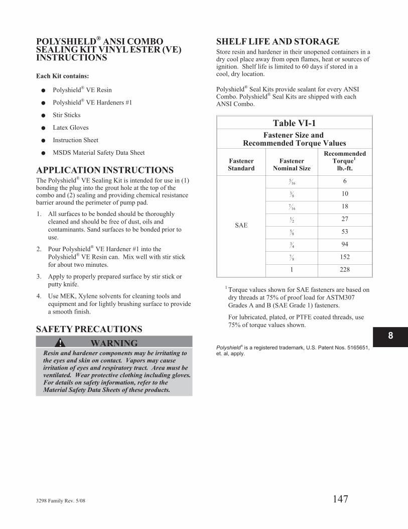
POLYSHIELD®
ANSI COMBOSEALING KIT VINYL ESTER (VE)INSTRUCTIONS
Each Kit contains:
� Polyshield® VE Resin
� Polyshield® VE Hardeners #1
� Stir Sticks
� Latex Gloves
� Instruction Sheet
� MSDS Material Safety Data Sheet
APPLICATION INSTRUCTIONSThe Polyshield® VE Sealing Kit is intended for use in (1)bonding the plug into the grout hole at the top of thecombo and (2) sealing and providing chemical resistancebarrier around the perimeter of pump pad.
1. All surfaces to be bonded should be thoroughly
cleaned and should be free of dust, oils and
contaminants. Sand surfaces to be bonded prior to
use.
2. Pour Polyshield® VE Hardener #1 into the
Polyshield® VE Resin can. Mix well with stir stick
for about two minutes.
3. Apply to properly prepared surface by stir stick or
putty knife.
4. Use MEK, Xylene solvents for cleaning tools and
equipment and for lightly brushing surface to provide
a smooth finish.
SAFETY PRECAUTIONS
▲! WARNINGResin and hardener components may be irritating tothe eyes and skin on contact. Vapors may causeirritation of eyes and respiratory tract. Area must beventilated. Wear protective clothing including gloves.For details on safety information, refer to theMaterial Safety Data Sheets of these products.
SHELF LIFE AND STORAGEStore resin and hardener in their unopened containers in adry cool place away from open flames, heat or sources ofignition. Shelf life is limited to 60 days if stored in acool, dry location.
Polyshield® Seal Kits provide sealant for every ANSICombo. Polyshield® Seal Kits are shipped with eachANSI Combo.
Table VI-1
Fastener Size andRecommended Torque Values
FastenerStandard
FastenerNominal Size
RecommendedTorque
1
lb.-ft.
SAE
516 6
38 10
716 18
12 27
58 53
34 94
78 152
1 228
1 Torque values shown for SAE fasteners are based on
dry threads at 75% of proof load for ASTM307
Grades A and B (SAE Grade 1) fasteners.
For lubricated, plated, or PTFE coated threads, use
75% of torque values shown.
Polyshield®
is a registered trademark, U.S. Patent Nos. 5165651,
et. al, apply.
3298 Family Rev. 5/08 147
8


HOW TO ORDER
When ordering parts call
1-800-446-8537
or your local Goulds Representative
EMERGENCY SERVICE
Emergency parts service is available
24 hours/day, 365 days/year...
Call 1-800-446-8537
Form No. I3298 5/08
Visit our website at www.gouldspumps.com
© 2007 Goulds Pumps, Incorporateda subsidiary of ITT Corporation
How did we measure up?It is our sincere intention to exceed our customers' expections on every order.
Tell us whether we achieved our goal on your order.Please take our customer satisfaction survey online at:
http://www.gouldspumps.com/feedbacksurvey.html
We appreciate you taking the time to provide your feedback.Thank you for buying Goulds pumps, parts, and controls.