Embed Size (px)
Citation preview
IOM-12TH
Doc 12893 Rev. A
Ref. ID: 100210 ©2009 Groth Corporation
Installation, Operation and Maintenance Manual for
Spring Loaded Thief Hatch
Model 12-TH
Page 2 of 13
TABLE OF CONTENTS
INTRODUCTION 3
DESIGN AND FUNCTION 4
a. FIGURE 1 – TYPICAL TANK I NSTALLATION 4 b. FIGURE 2 – PRESSURE RELIEF 4 c. FIGURE 3 – VACUUM RELIEF 4
SAFETY WARNINGS 5
INSPECTION AND STORAGE 6
INSTALLATION 6
d. TABLE 1 – RECOMMENDEDTORQUE VALUES 6 MAINTENANCE 7
e. FIGURE 4 – VALVE CROSS SECTION 7 f. FIGURE 5 – THIEF ASSEMBLY SECTION VIEW 8 g. TABLE 2 – BILL OF MATERIAL 8
VALVE TESTING PROCEDURE 9
h. TABLE 3 – SEAT LEAKAGE TEST CRITERIA 9 SOFT GOODS KITS 9
MODEL IDENTIFICATION 10
PRODUCT LIMITED WARRANTY 11
Page 3 of 13
INTRODUCTION
The Thief Hatch is a pressure and vacuum relief valves are used on liquid storage tanks and other
process vessels or systems to prevent structural damage due to excess internal pressure or vacuum.
The thief hatch also permits access to the contents of the tank.
Storage tanks are pressurized when liquid is pumped in, compressing the existing vapor or when
rising temperatures cause increased evaporation or expansion of existing vapor. Conversely, a
vacuum condition may be created when pumping out or due to falling temperature. To prevent tank
damage, vapor must be allowed into or out of the tank at specified pressure/vacuum conditions. The
volume rate of venting depends upon the tank size, volatility of the tank contents, the pumping rates
and the temperature. Refer to API Standard 2000, ISO 28300, or local regulations for the procedures
to determine venting requirements.
A relief valve must be carefully maintained by a qualified valve technician. It should only be
assembled under clean conditions, preferably in a service shop environment. Carefully read and
understand this manual before installing or attempting to repair a valve.
For information not contained in this manual, please contact:
Groth Corporation
13650 N. Promenade Blvd.
Stafford, TX, 77477 USA
Phone: 281-295-6800
Fax: 281-295-6999
www.grothcorp.com
Page 4 of 13
DESIGN AND FUNCTION
Tank protection equipment typically includes an operating valve which is designed to provide
pressure/vacuum relief under normal pump in/out and thermal breathing conditions. An emergency relief
valve can also provide both pressure and vacuum relief and normally it is sized to provide pressure relief
if there is a fire in the immediate vicinity of the tank. It may also be sized by the tank designer to provide
protection in the event of equipment failure (such as the rupture of a process steam line or an inert gas
blanketing system failing “wide open”) or operator error.
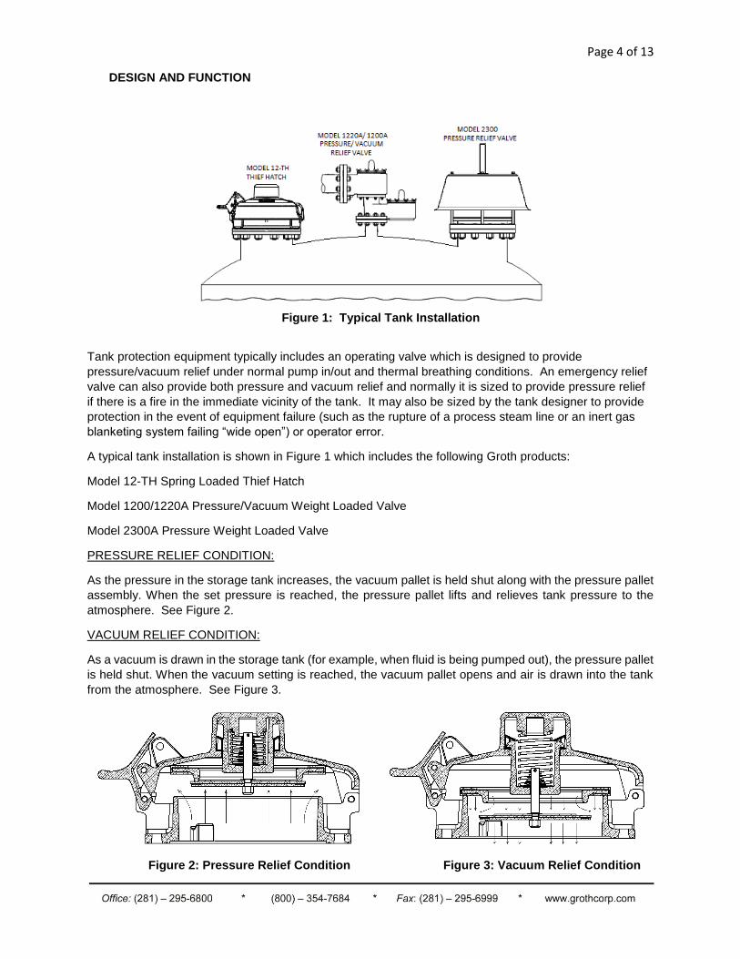
A typical tank installation is shown in Figure 1 which includes the following Groth products:
Model 12-TH Spring Loaded Thief Hatch
Model 1200/1220A Pressure/Vacuum Weight Loaded Valve
Model 2300A Pressure Weight Loaded Valve
PRESSURE RELIEF CONDITION:
As the pressure in the storage tank increases, the vacuum pallet is held shut along with the pressure pallet
assembly. When the set pressure is reached, the pressure pallet lifts and relieves tank pressure to the
atmosphere. See Figure 2.
VACUUM RELIEF CONDITION:
As a vacuum is drawn in the storage tank (for example, when fluid is being pumped out), the pressure pallet
is held shut. When the vacuum setting is reached, the vacuum pallet opens and air is drawn into the tank
from the atmosphere. See Figure 3.
Figure 2: Pressure Relief Condition Figure 3: Vacuum Relief Condition
Figure 1: Typical Tank Installation
Page 5 of 13
SAFETY WARNINGS
This section is an overview of safety guidelines that should be followed during the
installation, operation and maintenance of Groth Spring Loaded Thief Hatch. To understand
the context of these instructions and warnings, it is necessary to completely read and
understand the contents of this manual.
The purpose of a spring loaded thief hatch relief valve is to prevent excessive pressure or
vacuum in a tank or process system. The valve must be designed for the proper Maximum
Allowable Working Pressure (MAWP) and flow requirements of the system. Consult API
Standard 2000, ISO 28300, or local regulations for tank protection sizing procedures. An
improperly specified or functioning relief valve may result in structural damage to the tank or
system, and can cause severe personal injury or death.
Valves are set at the factory according to purchase order specifications. Do NOT change
pressure ratings by adding additional weights to the pallet assembly without consulting the
factory or your local Groth representative. Adding weights to a valve may restrict pallet lift
and reduce the valve’s rated flow capacity.
DO NOT mix pressure/vacuum pallet assemblies. Failure to ensure that both pallet
assemblies are installed in the correct location can change the pressure and vacuum relief
settings or restrict lift of the pallet. This can cause a tank failure.
DO NOT attempt to remove the valve from the tank or process vessel without first bleeding all
pressure from the system. ALTERNATIVE MEANS OF PRESSURE RELIEF MUST BE
PROVIDED WHEN THE VALVE IS OUT OF SERVICE.
If the valve has been exposed to process vapors while in service, observe all plant procedures
and Material Safety Data Sheets (MSDS) for the products in the system when inspecting,
adjusting or servicing the valve. Take appropriate safety precautions regarding eye
protection, respiration and skin contact.
The tank pressure required to discharge the normal or emergency venting requirements of the
tank will be increased by the amount of back pressure in the discharge header, on a pipe away
valve configuration. Maximum possible discharge header pressure must be considered when
sizing the pressure relief valve.
Page 6 of 13
INSPECTION AND STORAGE
The thief hatch is carefully packaged to prevent damage or contamination during shipping. Inspect all
equipment when it is received; report any damage to the carrier immediately. The valve should be
protected during handling and storage. Before installation, inspect the unit for indications of physical
damage or internal contamination. If these are observed, the valve must be disassembled, cleaned
and repaired before installation.
INSTALLATION
A typical thief hatch installation on a tank or vessel is illustrated in Figure 1, Page 4. Groth's spring
loaded Pressure/Vacuum Relief Valves are designed to provide tank protection for both pressure
and/or vacuum. The valve is marked with a rated flow capacity at 100% over-pressure. Consult
factory for performance under other conditions
WARNING: The valve must be installed in a vertical position as shown in Figure 1, Page 4. To
achieve nominal flow capacity, the tank nozzle bore must be at least the same nominal
dimension as the relief valve inlet body.
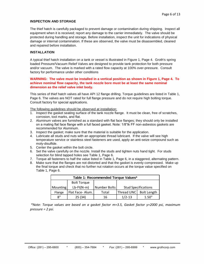
This series of thief hatch valves all have API 12 flange drilling. Torque guidelines are listed in Table 1,
Page 6. The valves are NOT rated for full flange pressure and do not require high bolting torque.
Consult factory for special applications.
The following guidelines should be observed at installation: 1. Inspect the gasket seating surface of the tank nozzle flange. It must be clean, free of scratches,
corrosion, tool marks, and flat. 2. Aluminum valves are furnished as a standard with flat face flanges; they should only be installed
on a mating flat face flange with a full faced gasket. Note: 1/8”tk FF non-asbestos gaskets are recommended for Aluminum.
3. Inspect the gasket; make sure that the material is suitable for the application. 4. Lubricate all studs and nuts with an appropriate thread lubricant. If the valve will see high
temperature service or stainless steel fasteners are used, apply an anti-seize compound such as moly-disulfide.
5. Center the gasket within the bolt circle. 6. Set the valve carefully on the nozzle. Install the studs and tighten nuts hand tight. For studs
selection for blind tapped holes see Table 1, Page 6. 7. Torque all fasteners to half the value listed in Table 1, Page 6, in a staggered, alternating pattern. 8. Make sure that the flanges are not distorted and that the gasket is evenly compressed. Make up
the final torque and check that no further nut rotation occurs at the torque value specified on Table 1, Page 6.
Mounting
Bolt Torque
Lb-Ft(N-m) Number Bolts
Flange Flat Face- Alum. Total Thread UNC Bolt Length
8" 25 (34) 16 1/2-13 1.50"
Stud Specifications
Table 1: Recommended Torque Values*
*Note: Torque values are based on a gasket factor m=3.5, Gasket factor y=2000 psi, maximum pressure = 2 psi.
Page 7 of 13
MAINTENANCE
Groth Corporation recommends that all
service performed on a thief hatch relief
valve is done at a Groth Authorized
Repair Dealer. Contact Groth Corporation
for your local authorized repair dealer.
Trained mechanics with specialized test
equipment will ensure that the valve is
accurately set.
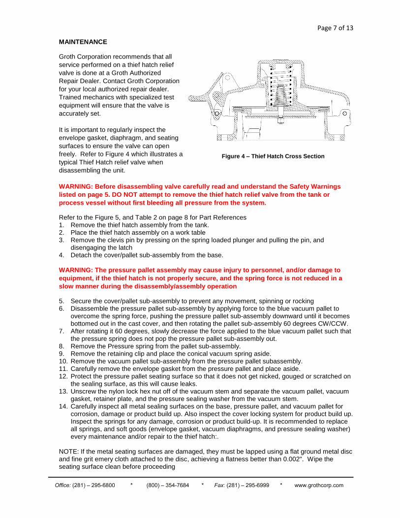
It is important to regularly inspect the
envelope gasket, diaphragm, and seating
surfaces to ensure the valve can open
freely. Refer to Figure 4 which illustrates a
typical Thief Hatch relief valve when
disassembling the unit.
WARNING: Before disassembling valve carefully read and understand the Safety Warnings
listed on page 5. DO NOT attempt to remove the thief hatch relief valve from the tank or
process vessel without first bleeding all pressure from the system.
Refer to the Figure 5, and Table 2 on page 8 for Part References 1. Remove the thief hatch assembly from the tank. 2. Place the thief hatch assembly on a work table 3. Remove the clevis pin by pressing on the spring loaded plunger and pulling the pin, and
disengaging the latch 4. Detach the cover/pallet sub-assembly from the base.
WARNING: The pressure pallet assembly may cause injury to personnel, and/or damage to
equipment, if the thief hatch is not properly secure, and the spring force is not reduced in a
slow manner during the disassembly/assembly operation
5. Secure the cover/pallet sub-assembly to prevent any movement, spinning or rocking 6. Disassemble the pressure pallet sub-assembly by applying force to the blue vacuum pallet to
overcome the spring force, pushing the pressure pallet sub-assembly downward until it becomes bottomed out in the cast cover, and then rotating the pallet sub-assembly 60 degrees CW/CCW.
7. After rotating it 60 degrees, slowly decrease the force applied to the blue vacuum pallet such that the pressure spring does not pop the pressure pallet sub-assembly out.
8. Remove the Pressure spring from the pallet sub-assembly. 9. Remove the retaining clip and place the conical vacuum spring aside. 10. Remove the vacuum pallet sub-assembly from the pressure pallet subassembly. 11. Carefully remove the envelope gasket from the pressure pallet and place aside. 12. Protect the pressure pallet seating surface so that it does not get nicked, gouged or scratched on
the sealing surface, as this will cause leaks. 13. Unscrew the nylon lock hex nut off of the vacuum stem and separate the vacuum pallet, vacuum
gasket, retainer plate, and the pressure sealing washer from the vacuum stem. 14. Carefully inspect all metal sealing surfaces on the base, pressure pallet, and vacuum pallet for
corrosion, damage or product build up. Also inspect the cover locking system for product build up. Inspect the springs for any damage, corrosion or product build-up. It is recommended to replace all springs, and soft goods (envelope gasket, vacuum diaphragms, and pressure sealing washer) every maintenance and/or repair to the thief hatch:.
NOTE: If the metal seating surfaces are damaged, they must be lapped using a flat ground metal disc and fine grit emery cloth attached to the disc, achieving a flatness better than 0.002". Wipe the seating surface clean before proceeding
Figure 4 – Thief Hatch Cross Section
Page 8 of 13
15. It is recommended to replace the retaining ring and vacuum stem every maintenance and/or
repair to the thief hatch to prevent the wearing of the vacuum stem in the groove area, and maintaining a tight fit with the retaining ring.
16. After inspection of all the components for damage, and replacement as needed. Clean all the components and sealing surfaces
17. Assemble in reverse order, apply 4-10 complete wraps of Teflon thread sealing tape to the vacuum stem, and apply 120 in-lbs of torque to tighten the nylon lock washer onto the vacuum stem.
18. Verify that the pallets are back in their proper location. Make sure that the pallet assemblies sit flat on the seat and that it is not cocked when the cover is latched.
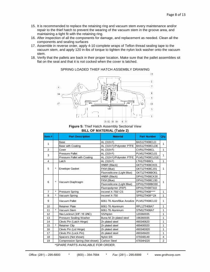
SPRING LOADED THIEF HATCH ASSEMBLY DRAWING
Figure 5: Thief Hatch Assembly Sectional View
BILL OF MATERIAL (Table 2)
Item # Part Description Material Part Number Qty.
Base AL (319-F) BAS12TH08CLD
Base with Coating AL (319-F)/Polyester PTFE BAS12TH08CLDE
2 Cover AL (319-F) CVR12TH08CL 1
Pressure Pallet AL (319-F) PLM12TH08CL01
Pressure Pallet with Coating AL (319-F)/Polyester PTFE PLM12TH08CL01E
4 Latch AL (319-F) LTH12TH08CL 1
HNBR (Black) GKT12TH08CK01
FKM (Blue) GKT12TH08CJ01
Fluorosilicone (Light Blue) GKT12TH08BO01
HNBR (Black) DPH12TH08CK30
FKM (Blue) DPH12TH08CJ30
Fluorosilicone (Light Blue) DPH12TH08BO30
Fluoropolymer (FEP) DPH12TH087310
7 * Pressure Spring Inconel X-750/ CS SPR12TH08**** 1
8 * Vacuum Spring Inconel X-750 SPR12TH08**Z4 1
9 Vacuum Pallet 6061-T6 Alum/Blue Anodize PLM12TH08CL02 1
10 Retainer Plate 6061-T6 Aluminum RPL12TH08A7 1
11 * Vacuum Stem 6061-T6 Aluminum STM12TH08A7 1
12 Hex Locknut (3/8”-16 UNC) SS/Nylon 120360035 1
13 Pressure Sealing Washer Buna-N/ Zn plated steel 196360035 1
14 Clevis Pin (Latch Hinge) Zn plated steel 490340620 1
15 * Retainer Clip Zn plated steel 489400020 1
16 Clevis Pin (Lid Hinge) Zn plated steel 49034E820 1
17 Clevis Pin (Lock Pin) Zn plated steel 490349420 1
18 Spacers (Not shown) Nylon 6/6 479348149 4
19 Compression Spring (Not shown) Carbon Steel 47834H220 2
Envelope Gasket
6 Vacuum Diaphragm
1 1
3 1
1
1
*
*
5
*SPARE PARTS AVAILABLE FOR ORDER.
Page 9 of 13
VALVE TESTING PROCEDURE
General Information
1. Use only appropriate testing equipment designated by local regulations (API 2000, ISO 28300, EN14015).
2. Calibrate all measuring devices according to device manufacturer schedule.
Seat Leakage Test (Pressure/Vacuum)
1. Test the pressure and/or vacuum seat leakage three times to verify leak tightness. Record all test pressure and vacuum readings on the Shop Data Sheet.
2. Slowly open the Test Stand Pressure Test or Vacuum Test valve (supply pressure). 3. Adjust the appropriate flow meter to achieve the specified flow rate listed Table 3 below. 4. With the valve flowing at the flow rate indicated in Table 3, read the test stand supply pressure
using the manometer or gauge. 5. The acceptance criteria for this test are that the peak pressure attained at the specified flow rate
be at least 90% for Pressure / 75% for Vacuum of the specified set pressure or vacuum listed on the sales order. Perform this test three times to verify proper operation.
6. If the valve fails to meet the 90% for pressure / 75% for Vacuum criteria, it must be disassembled and the pallet, envelope gasket, diaphragm or seat repaired or replaced, and retest the valve.
7. Record the test results under the Seat Leakage Test 1-3 (Pressure/Vacuum) on a Shop Data Sheet.
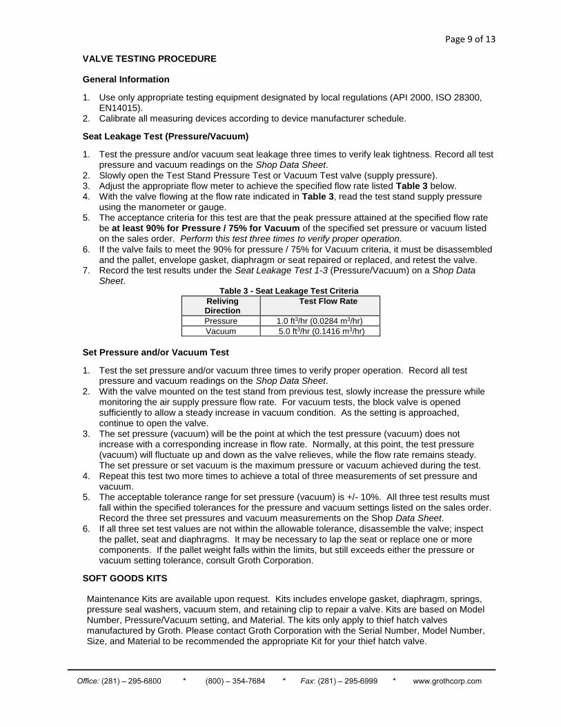
Table 3 - Seat Leakage Test Criteria
Reliving Direction
Test Flow Rate
Pressure 1.0 ft3/hr (0.0284 m3/hr)
Vacuum 5.0 ft3/hr (0.1416 m3/hr)
Set Pressure and/or Vacuum Test
1. Test the set pressure and/or vacuum three times to verify proper operation. Record all test pressure and vacuum readings on the Shop Data Sheet.
2. With the valve mounted on the test stand from previous test, slowly increase the pressure while monitoring the air supply pressure flow rate. For vacuum tests, the block valve is opened sufficiently to allow a steady increase in vacuum condition. As the setting is approached, continue to open the valve.
3. The set pressure (vacuum) will be the point at which the test pressure (vacuum) does not increase with a corresponding increase in flow rate. Normally, at this point, the test pressure (vacuum) will fluctuate up and down as the valve relieves, while the flow rate remains steady. The set pressure or set vacuum is the maximum pressure or vacuum achieved during the test.
4. Repeat this test two more times to achieve a total of three measurements of set pressure and vacuum.
5. The acceptable tolerance range for set pressure (vacuum) is +/- 10%. All three test results must fall within the specified tolerances for the pressure and vacuum settings listed on the sales order. Record the three set pressures and vacuum measurements on the Shop Data Sheet.
6. If all three set test values are not within the allowable tolerance, disassemble the valve; inspect the pallet, seat and diaphragms. It may be necessary to lap the seat or replace one or more components. If the pallet weight falls within the limits, but still exceeds either the pressure or vacuum setting tolerance, consult Groth Corporation.
SOFT GOODS KITS
Maintenance Kits are available upon request. Kits includes envelope gasket, diaphragm, springs, pressure seal washers, vacuum stem, and retaining clip to repair a valve. Kits are based on Model Number, Pressure/Vacuum setting, and Material. The kits only apply to thief hatch valves manufactured by Groth. Please contact Groth Corporation with the Serial Number, Model Number, Size, and Material to be recommended the appropriate Kit for your thief hatch valve.
Page 10 of 13
IX. MODEL NUMBER IDENTIFICATION
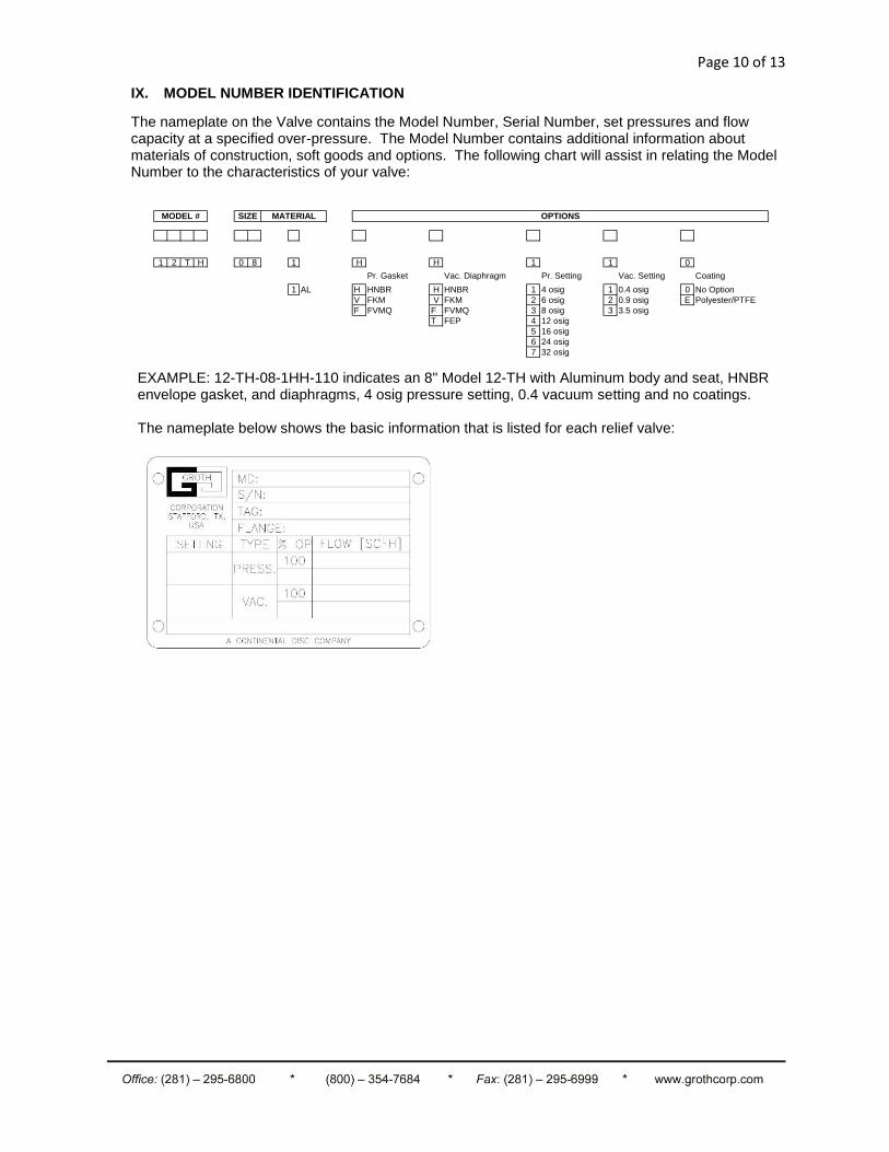
The nameplate on the Valve contains the Model Number, Serial Number, set pressures and flow capacity at a specified over-pressure. The Model Number contains additional information about materials of construction, soft goods and options. The following chart will assist in relating the Model Number to the characteristics of your valve:
1 2 T H 0 8 1 H H 1 1 0
Pr. Gasket Vac. Diaphragm Pr. Setting Vac. Setting Coating
1 AL H HNBR H HNBR 1 4 osig 1 0.4 osig 0 No Option
V FKM V FKM 2 6 osig 2 0.9 osig E Polyester/PTFE
F FVMQ F FVMQ 3 8 osig 3 3.5 osig
T FEP 4 12 osig
5 16 osig
6 24 osig
7 32 osig
SIZE MATERIAL OPTIONSMODEL #
EXAMPLE: 12-TH-08-1HH-110 indicates an 8" Model 12-TH with Aluminum body and seat, HNBR envelope gasket, and diaphragms, 4 osig pressure setting, 0.4 vacuum setting and no coatings. The nameplate below shows the basic information that is listed for each relief valve:
Page 11 of 13
IX. PRODUCT LIMITED WARRANTY
Only Groth’s Product Limited Warranty terms apply to purchase orders accepted by Groth
Corporation.
Seller warrants that products that are manufactured by Seller are manufactured in accordance with
published specifications and free from defects in materials and/or workmanship for a period of (12)
twelve months. Seller, at its option, will repair or replace any products returned intact to the factory,
transportation charges prepaid, which Seller, upon inspection, determines to be defective in material
and/or workmanship. The foregoing shall constitute the sole remedy for any breach of Seller’s
warranty.
THERE ARE NO UNDERSTANDINGS, AGREEMENTS, REPRESENTATIONS, OR WARRANTIES,
EXPRESS OR IMPLIED (INCLUDING MERCHANTABILITY OR FITNESS FOR A PARTICULAR
PURPOSE REGARDING PRODUCTS) UNLESS SPECIFIED IN THE SALES CONTRACT. THIS
CONTRACT STATES THE ENTIRE OBLIGATION OF SELLER.
Seller makes no warranties, either express or implied, except as provided herein, including without
limitation thereof, warranties as to marketability, merchantability, for a particular purpose or use, or
against infringement of any patent of products. In no event shall Seller be liable for any direct,
incidental or consequential damages of any nature, or losses or expenses resulting from any
defective new product or the use of any such product, including any damages for loss of time,
inconvenience, or loss of use of any such product.
The original Manufacturer shall be solely responsible for the design, development, supply, production,
and performance of its products hereunder, and the protection of its trade name or names, if any. It
assumes no responsibility, for products modified or changed by its agent or customer, or any other
third party. Any such modifications or changes to products sold by Seller hereunder shall make the
product limited warranty null and void.
Groth assumes no responsibility for products modified or changed by Customer or any other third
party. Any such modifications or changes to products sold by Groth hereunder shall make the
product limited warranty null and void. Groth shall be under no obligation to manufacture, sell or
supply, or to continue to manufacture, sell, or supply any of the products.

Page 12 of 13
Page 13 of 13
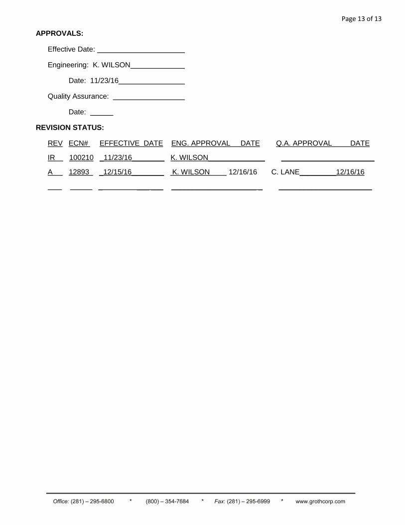
APPROVALS:
Effective Date:
Engineering: K. WILSON
Date: 11/23/16
Quality Assurance:
Date:
REVISION STATUS:
REV ECN# EFFECTIVE DATE ENG. APPROVAL DATE Q.A. APPROVAL DATE
IR 100210 _11/23/16________ K. WILSON______________ _______________________
A 12893 _12/15/16________ K. WILSON 12/16/16 C. LANE_________12/16/16
_ ___ ___ _____________________ _ _______________________