Embed Size (px)
Citation preview
INSTALLATION, OPERATION AND MAINTENANCE INSTRUCTIONS
Line VTI
INSTRUÇÕES DE INSTALAÇÃO, OPERAÇÃO E MANUTENÇÃO
IMBIL - BOMBAS VTI
Mr. Propietor
Congratulations! You just have purchased an easy to assemble equipment, designed and manufactured with the most advanced technology, having an excellent performance and providing easy maintenance.
The aim of this manual is to inform the user about the details of the equipment and the proper
techniques for Installation, Operation and Maintenance.
IMBIL recommends the installation and handling of this piece of equipment according to the technical specifications and the instructions of this manual. IMBIL also recommends that this piece of equipment be used according to the service conditions for which it was selected (volumetric flow, total head, speed, voltage, frequency and temperature).
IMBIL is not responsible for faults due to ignorance of these service orientations. This Manual should
be used by the people in charge of installation, operation and maintenance.
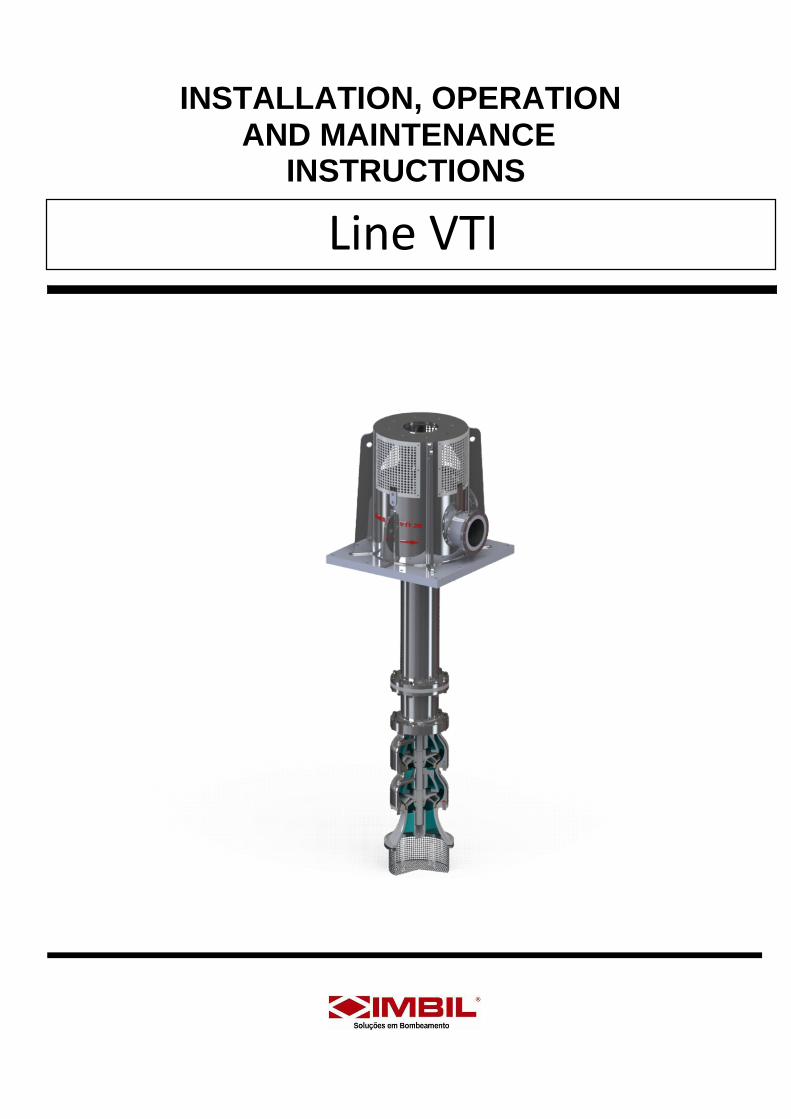
In case the equipment needs to be verified or when ordering spare parts, please indicate the part code, model, pump series and also the serial number. This information found on the identification plate, and engraved in low relief on the suction flange.
NOTE: Right after receiving the WARRANTY DEED of your equipment, please fill in the data and
send the custmer to IMBIL, so that the information exchange between IMBIL and the client can be facilitated.
INSTRUÇÕES DE INSTALAÇÃO, OPERAÇÃO E MANUTENÇÃO
IMBIL - BOMBAS VTI
INDEX
Sumário
1 - INSPECTION UPON RECEIPT ...................................................................................................................................................... 1
2 - LIFTING .......................................................................................................................................................................................... 1
3 - STORAGE ...................................................................................................................................................................................... 1
4 – SAFETY RECOMMENDATION ..................................................................................................................................................... 1
5 – OPERATING SAFETY ................................................................................................................................................................... 2
5.1 – External Connections .......................................................................................................................................................... 2
5.2 – Starting the Pump ................................................................................................................................................................ 2
5.3 - Low Flow .............................................................................................................................................................................. 2
5.4 – High Flows .......................................................................................................................................................................... 2
5.5 - Operating Inspections .......................................................................................................................................................... 2
6 – SECURITY FOR MAINTENANCE ................................................................................................................................................. 2
6.1 - Inspection or Repairs ........................................................................................................................................................... 2
6.2 – Isolating Pump..................................................................................................................................................................... 2
6.3 – Drainage Lube Oil ............................................................................................................................................................... 2
7 – ELECTRICAL CONNECTIONS ...................................................................................................................................................... 2
8 – NOISE LEVELS ............................................................................................................................................................................. 3
9 - STARTER ....................................................................................................................................................................................... 3
10 – HEAD OF DISCHARGE ............................................................................................................................................................... 3
11 - COLUMN ...................................................................................................................................................................................... 3
12 – BODY PUMP (BOWL) .................................................................................................................................................................. 3
13 – CHECK LIST FOR INSTALLATION ............................................................................................................................................. 3
14 - FUNDATION ................................................................................................................................................................................. 3
15 – CLEANING THE PUMP ............................................................................................................................................................... 3
16 – INSTALLING THE PUMP ............................................................................................................................................................. 4
16.1 - Assembling the Body Pump: .............................................................................................................................................. 4
16.2 - Mounting Head Discharge .................................................................................................................................................. 4
16.3 - Mounting the Motor ............................................................................................................................................................ 4
16.4 - Position Adjustment Work Rotor ........................................................................................................................................ 4
17 – VERIFICATION BEFORE START THE PUMP ............................................................................................................................ 4
18 – INITIAL START ............................................................................................................................................................................ 5
19 - RECOMMENDATION ................................................................................................................................................................... 5
20 – PERIODIC INSPECTION ............................................................................................................................................................. 5
21 – LUBRICATION ............................................................................................................................................................................. 5
21.1 - Bearing Column ................................................................................................................................................................. 5
21.2 - Acionadores ....................................................................................................................................................................... 5
22 - TROUBLESHOOTING AND CAUSES .......................................................................................................................................... 6
23. 1 - Head Discharge .................................................................................................................................................................... 7
23.2 - Column Top........................................................................................................................................................................ 7
23.3 - Column ............................................................................................................................................................................... 7
23.4 - Body Pump......................................................................................................................................................................... 7
24 – REPAIRS ..................................................................................................................................................................................... 7
25 – BODY MOUNT ............................................................................................................................................................................. 8
26 – INSPECTION AND CLEANING ................................................................................................................................................... 8
INSTRUÇÕES DE INSTALAÇÃO, OPERAÇÃO E MANUTENÇÃO
IMBIL - BOMBAS VTI
1
1 - INSPECTION UPON RECEIPT
Inspect the equipment as soon as it is received, check it
against the invoice, and notify immediately if any parts are missing or damaged.
1.1 Unpacking the Pump
Remove the material of the sealing unit. Discard all
materials in accordance with the sealant local
regulations. Inspect the drive to determine if any parts
been damaged or are missing.
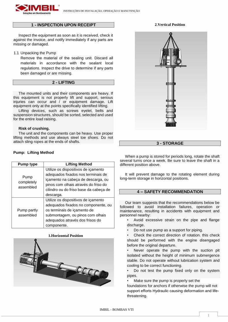
2 - LIFTING
The mounted units and their components are heavy. If this equipment is not properly lift and support, serious injuries can occur and / or equipment damage. Lift equipment only at the points specifically identified lifting.
Lifting devices, such as screws eyelet, belts and suspension structures, should be sorted, selected and used for the entire load raising.
Risk of crushing.
The unit and the components can be heavy. Use proper lifting methods and use always steel toe shoes. Do not attach sling ropes at the ends of shafts.
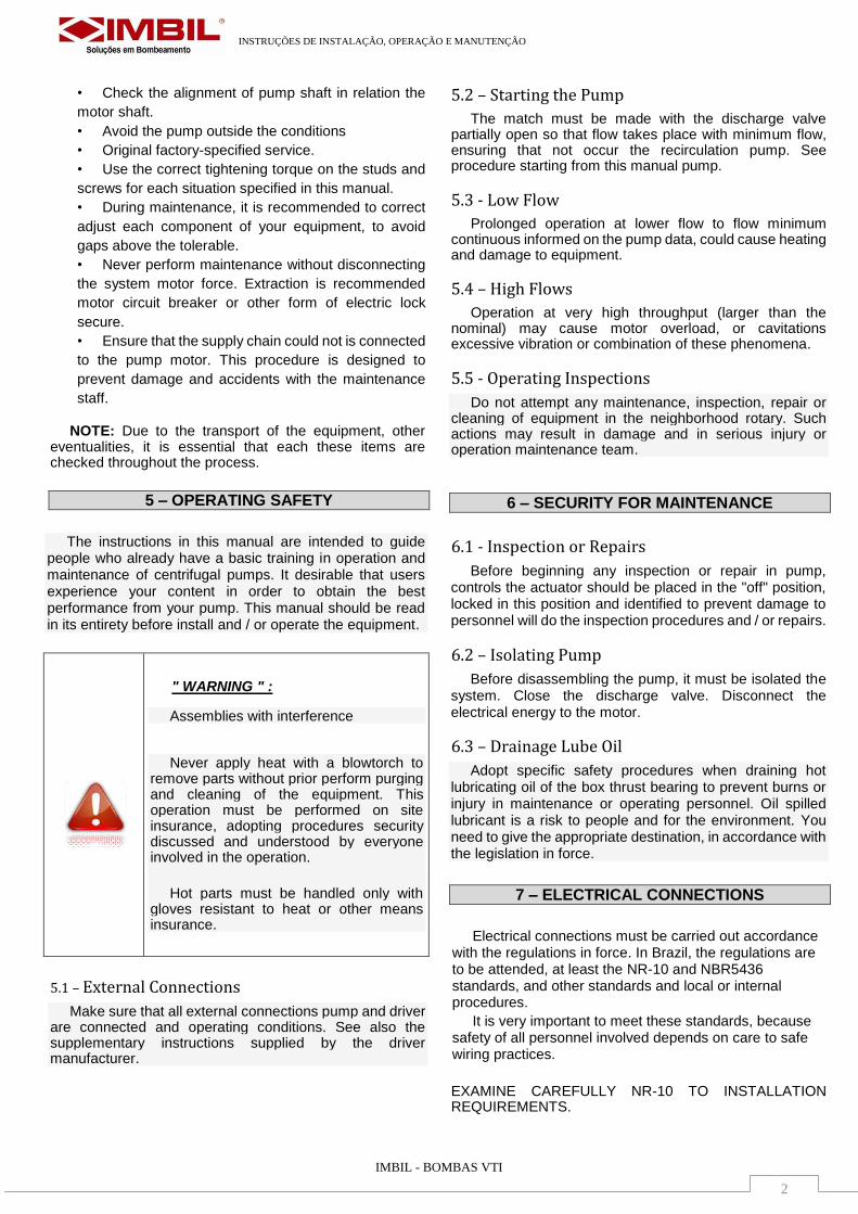
Pump: Lifting Method
Pump type Lifting Method
Pump
completely
assembled
Utilize os dispositivos de içamento
adequados fixados nos terminais de
içamento na cabeça de descarga, ou
pinos com olhais através do friso do
cilindro ou do friso base da cabeça de
descarga.
Pump partly
assembled
Utilize os dispositivos de içamento
adequados fixados no componente, ou
os terminais de içamento de
submontagem, ou pinos com olhais
adequados através dos frisos do
componente.
1.Horizontal Position
2.Vertical Position
3 - STORAGE
When a pump is stored for periods long, rotate the shaft several turns once a week. Be sure to leave the shaft in a different position above.
It will prevent damage to the rotating element during long-term storage in horizontal positions.
4 – SAFETY RECOMMENDATION
Our team suggests that the recommendations below be followed to avoid installation failures, operation or maintenance, resulting in accidents with equipment and personnel nearby:
• Avoid excessive strain on the pipe and flange
discharge.
• Do not use pump as a support for piping.
• Check the correct direction of rotation. this check
should be performed with the engine disengaged
before the original departure.
• Never operate the pump with the suction pit
isolated without the height of minimum submergence
stable. Do not operate without lubrication system and
cooling to be correct functioning.
• Do not test the pump fixed only on the system
pipes.
• Make sure the pump is properly set the
foundations for anchors if otherwise the pump will not
support efforts Hydraulic causing deformation and life-
threatening.
INSTRUÇÕES DE INSTALAÇÃO, OPERAÇÃO E MANUTENÇÃO
IMBIL - BOMBAS VTI
2
• Check the alignment of pump shaft in relation the
motor shaft.
• Avoid the pump outside the conditions
• Original factory-specified service.
• Use the correct tightening torque on the studs and
screws for each situation specified in this manual.
• During maintenance, it is recommended to correct
adjust each component of your equipment, to avoid
gaps above the tolerable.
• Never perform maintenance without disconnecting
the system motor force. Extraction is recommended
motor circuit breaker or other form of electric lock
secure.
• Ensure that the supply chain could not is connected
to the pump motor. This procedure is designed to
prevent damage and accidents with the maintenance
staff.
NOTE: Due to the transport of the equipment, other eventualities, it is essential that each these items are checked throughout the process.
5 – OPERATING SAFETY
The instructions in this manual are intended to guide people who already have a basic training in operation and maintenance of centrifugal pumps. It desirable that users experience your content in order to obtain the best performance from your pump. This manual should be read in its entirety before install and / or operate the equipment.
" WARNING " :
Assemblies with interference
Never apply heat with a blowtorch to remove parts without prior perform purging and cleaning of the equipment. This operation must be performed on site insurance, adopting procedures security discussed and understood by everyone involved in the operation.
Hot parts must be handled only with gloves resistant to heat or other means insurance.
5.1 – External Connections
Make sure that all external connections pump and driver are connected and operating conditions. See also the supplementary instructions supplied by the driver manufacturer.
5.2 – Starting the Pump
The match must be made with the discharge valve partially open so that flow takes place with minimum flow, ensuring that not occur the recirculation pump. See procedure starting from this manual pump.
5.3 - Low Flow
Prolonged operation at lower flow to flow minimum continuous informed on the pump data, could cause heating and damage to equipment.
5.4 – High Flows
Operation at very high throughput (larger than the nominal) may cause motor overload, or cavitations excessive vibration or combination of these phenomena.
5.5 - Operating Inspections
Do not attempt any maintenance, inspection, repair or cleaning of equipment in the neighborhood rotary. Such actions may result in damage and in serious injury or operation maintenance team.
6 – SECURITY FOR MAINTENANCE
6.1 - Inspection or Repairs
Before beginning any inspection or repair in pump, controls the actuator should be placed in the "off" position, locked in this position and identified to prevent damage to personnel will do the inspection procedures and / or repairs.
6.2 – Isolating Pump
Before disassembling the pump, it must be isolated the system. Close the discharge valve. Disconnect the electrical energy to the motor.
6.3 – Drainage Lube Oil
Adopt specific safety procedures when draining hot lubricating oil of the box thrust bearing to prevent burns or injury in maintenance or operating personnel. Oil spilled lubricant is a risk to people and for the environment. You need to give the appropriate destination, in accordance with the legislation in force.
7 – ELECTRICAL CONNECTIONS
Electrical connections must be carried out accordance with the regulations in force. In Brazil, the regulations are to be attended, at least the NR-10 and NBR5436 standards, and other standards and local or internal procedures.
It is very important to meet these standards, because safety of all personnel involved depends on care to safe wiring practices.
EXAMINE CAREFULLY NR-10 TO INSTALLATION REQUIREMENTS.
INSTRUÇÕES DE INSTALAÇÃO, OPERAÇÃO E MANUTENÇÃO
IMBIL - BOMBAS VTI
3
The electric starter must be logged in according to the manufacturer's instructions. These instructions include directions about devices protection against high temperatures in the windings or bearing, fault currents to earth overcurrent or others. Check that the power supply meets equipment requirements as indicated on the nameplate driver identification. There is a device for emergency stop trigger, given the item 12.2.1 c) NR-12.
8 – NOISE LEVELS
The noise level is dependent on several factors, such as the type of starter used , the flow operation, the design of the pipe, and features acoustic installation.
9 - STARTER
Triggers solid axle where the drive shaft is solid and protrudes below the base mounting trigger. This type of trigger requires adjustable to connect the pump coupling.
10 – HEAD OF DISCHARGE
The discharge head support and the body of the motor and provides a pump discharge nozzle.
A shaft sealing arrangement is housed in discharge head for sealing the shaft passage where it leaves the passage of fluid. The shaft seal can be a mechanical sealing or set of conventional packing in pumps with column open ( shaft lubricated by the pumped fluid itself ) or a set of sealing the pipe bombs closed column.
11 - COLUMN
The column can be of two basic types, of which must be employed.
1- Open construction employing the fluid being
pumped to lubricate the bearings of the shaft
column.
2- Closed construction, employing a protective tube
surrounding the shaft and utilizing oil or other fluid
to lubricate the bearings of the axis of the column.
NOTA:
The column consists of a column tube assembly, which connects the body of the pump discharge head.
12 – BODY PUMP (BOWL)
The pump body is a set of one or more impellers rigidly mounted on a shaft that rotates and transmits energy to the fluid; bodies intended to contain the pressure increase and direct the fluid; suction bell, that directs fluid to the first rotor, and bearings located on the suction bell or body and everybody. The suction screen, usually fixed to the bell
Suction may be considered part of the pump body.
13 – CHECK LIST FOR INSTALLATION
The following points should be checked before starting installation to ensure proper installation and prevent delays:
1. In equipment powered by engines electrical, check that the voltage and frequency on the nameplate motor conform to the available energy. Also check the voltage and power panel motor control is suitable the power and motor voltage.
" WARNING " :
Any person who engages in inside the pumping station when one or more pumps are in operation must mandatory to use protective headset, regardless of time of stay in place.
2. Check the depth of the well against pump length to ensure whether there interference.
3. Check the liquid level in the proposed pit against the length of the pump. The pump body must be submerged at least up to the top of the first stage under all conditions Limpe o poço e a tubulação antes de instalar a bomba.
4. Clean well and the pipe before installing the pump.
5. Check the lifting devices loads in the facility to ensure that it is able to safely handle the equipment.
6. Check all connections from the pump (screws, nuts, etc...) for tightness. These were tightened properly before shipped from the factory; some loose connections in the transport. It is particularly noticeable in some stainless steels.
14 - FUNDATION
The foundation may consist of any material which permanently and rigidly support the head discharge and absorb the expected efforts that can be found in service.
CAUTION:
If bolts are used in leveling prisoners to level the base, the nuts must be away as much as possible before grouter the basis of foundation.
15 – CLEANING THE PUMP
Clean all parts from dust, dirt, material packaging and other objects and foreign substances. Wash the inside and outside of the pump with clean water. Remove any rust spots found in machined surfaces with fine sandpaper. Clean all threaded connections and fittings. Hubs column, it
INSTRUÇÕES DE INSTALAÇÃO, OPERAÇÃO E MANUTENÇÃO
IMBIL - BOMBAS VTI
4
must be shipped separately left in the box to prevent damage or loss of straightness.
16 – INSTALLING THE PUMP
Position the lifting equipment load so that it covers the opening in the center of the foundation.
NOTE:
The well and the pipe must be completely free of trash and loose dirt before starting the installation.
16.1 - Assembling the Body Pump:
A - Check the axial clearance of the pump body. While the pump body is in position horizontal, it should be possible to pull and push the shaft the pump body and measuring the current . Check that all screws are tightened. Do not lift or anyway handle the pump body by the shaft end.
B - Lift the pump body thoroughly with the aid of a clamp or shackle.
C - If using screen attach it to the pump body using the screws provided..
16.2 - Mounting Head Discharge
The discharge heads can be dispatched with sealing the components installed there.
A - Prepare the discharge head for lift using a suitable sling shackles and eyebolts in the head, or eyebolts installed on the flange head .
B - Go down the entire set until the print head rests on the foundation , aligning it with anchors . Flush set using shims and wedges between the pump and the foundation to level the pump.
CAUTION!
Do not use pins on the basis of survey discharge heads fused to raise only discharge head without having somehow prevented from turning. The best way to lift these heads is using eyebolts installed in the flange higher. Never lift the complete pump for eyebolts at this flange.
16.3 - Mounting the Motor
With the engine upright, install the assembly on head or support the driver . Note the position correct the motor connection box.
With the help of a qualified electrician install the wiring the engine and its accessories.
Make sure that no loose parts can be disengaging the motor before testing the direction of rotation.
Check that the motor shaft can rotate in both senses with hands .
Then perform the test of the direction of rotation. If the direction of rotation is incorrect, reverse the same.
Attach a dial indicator to the coupling half the motor side. Place the tip of the dial the bottom coupling mounted on the bearing anchor. Discontinue the engagement ring ( Partrubber ) so that both halves rotate together.
Slowly turn the shafts together. Read and record the values provided every 90 degrees. If these values exceed 0.005 inch ( 0.127 mm ) in overall reading the instrument moving realign the motor.
Repeat the read operation until the statement is within the recommended tolerance.
Tighten the screws of the motor and support the driver and check the reading of the alignment. If threading is changed, repeat the above step.
16.4 - Position Adjustment Work Rotor
Proper adjustment of the rotating assembly positions the impeller out of the pump body so you can get the best pump performance.
The impellers should be seated against the bodies Before starting the adjustment of the rotating assembly.
If the pump is subjected to a suction pressure that acts on the shaft tending to lift it. Make sure that the set is rotating in the bottom position before starting regulation .
The rotating assembly must first be erected with1 / 3 of the total axial clearance, previously verified in position
If after adjusting the pump does not attended your nominal capacity, the impellers can be downloaded stepwise to achieve the lowest possible setting without the drag of the rotor in the housing. Likewise, after adjustment rotors seem to be dragging, go the whole rotating one step at a time. Impellers dragging increase the power consumption and typically generate characteristic noise and vibrations can be felt. A marked increase in the current the engine will occur when the impellers creep in housing. This is particularly felt in the semi-open impellers.
17 – VERIFICATION BEFORE START THE PUMP
Before starting the pump for the first time after
installation or repair, check the following points:
1. Rotate the pump shaft by hand to ensure that the pump turns freely and that the rotors are correctly positioned.
2. Make sure that the adjusting nut on the top shaft is correctly locked into position.
3. The trigger was properly lubricated according with the instructions supplied with it?
4. The direction of rotation should be re-checked.
5. Check all the connections to the drive and control equipment.
6. Verify that all piping connections are tight and leak.
7. Make sure all bolts and screws fixing the foundations are tight.
8. Make sure all screws, nuts and connections piping are tight.
9. On pumps equipped with packing, make sure that the gland nuts are tight only hand - NOT tighten the gland before starting!
INSTRUÇÕES DE INSTALAÇÃO, OPERAÇÃO E MANUTENÇÃO
IMBIL - BOMBAS VTI
5
10. Check that the seal is adjusted and locked in position. Make sure all spacers and seal were removed , if necessary , locked in working position before starting the match of pump.
WARNING:
A coupling guard will be provided with all pumps with adjustable rigid coupling, bearing anchor or flexible coupling. this coupling guard must be secured in place before starting the pump to avoid possible contact with the parties rotating.
18 – INITIAL START
If the discharge line has a valve lock, this should be partially open for initial departure. The discharge valve partially closed is necessary to add load to the system..
The lack of controls to keep the flow within the limits of the pump and motor can cause serious damage.
Crank the pump and observe the operation. If there any difficulty, excessive noise or vibration beyond limits, stop the pump immediately and consult TROUBLESHOOTING GUIDE later this manual.
DANGER:
USE OF GREATER CAUTION IF NECESSARY BLEED DRAIN OR HAZARDOUS LIQUIDS. USE CLOTHING PROPER PROTECTION IN THE PRESENCE OF CÁUTICOS LIQUID, CORROSIVE, VOLATILE, FLAMMABLE OR HOT. NOT BREATHE TOXIC FUMES. DO NOT ALLOW THE PRESENCE OF SPARKS, SPARKS, FLAMES OR SURFACES HEATED IN NEIGHBORHOODS OF EQUIPMENT.
Ensure that the unit is purged of all vapors or air trapped in pump or system. Open the discharge valves to operate slowly drive the design conditions.
Carefully check the pump as leaks, loose connections or improperly operated.
If possible, the pump should be left running for about half an hour in the early game. It will allow the bearings, seals or packing will regularize and reduce the possibility of problems in future matches.
NOTE:
If there is the presence of abrasive or dirt on departure pump, the pump at initial start should be left function until the pumped fluid is clean. Stop when this pump is full of loads abrasives (as sometimes occurs in initial start) can lock the pump and cause more damage than if the pump is kept running.
CAUTION:
Every effort should be done to keep abrasive outside the pipes, suction pit. So that abrasives from entering the pump.
19 - RECOMMENDATION
• We recommend a periodic inspection as best way to avoid breakage and reduce costs maintenance to a minimum. Maintenance personnel must examine the plant
every time the pump is inspected: a change in the noise level, the increase vibration or deterioration of pump performance may be an indication of problems that ahead.
• Any deviation in performance or operation expected can be explained by a change or specific cause. Determining the cause of any change in performance or operation is essential so that the correction of the deviation can be made - either if correction is made by the user or reported to factory.
• Changes in the initial performance can indicate changes in system conditions, wear or the imminent breakdown of equipment.
20 – PERIODIC INSPECTION
A monthly periodical inspection is suggested for all equipment. During this inspection, the pump and the starter should be inspected for performance, changes in noise level or the level of vibration or loose bolts or loose pipes, accumulation of dirt or corrosion. Clean and repaint all areas that are rusted or corroded.
21 – LUBRICATION
Besides lubricating the packing box and / or column shaft lubrication and bearing lubrication anchor the pump, the pump should not require lubrication . In the water pumps , the bearing bell or suction body must be re- lubricated with grease whenever there are repairs to the pump body.
Any action is needed lubrication only when repairs are made to the body pump.
Oil pumps which pump or have bearing suction coal, rubber, epoxy or Teflon or have no bearing lubrication of suction grease.
21.1 - Bearing Column
Pumps open column have their bearings lubricated by the pumped liquid itself , being only necessary to pre- lubrication pumps and endowed with long columns where the static level liquid is more than 10 m below the head discharge.
In this case the pre lubrication is required, usually done by injecting water along the axis.
The pumps have closed column bearings be lubricated by oil or clean water.
In the case of oil lubrication, the lubricant these bearings is in the reservoir at the head discharge being fed in protective tube shaft through voltage bushing.
21.2 - Acionadores
Os acionadores, tal como a bomba, requerem atenção periódica. Consulte o manual de instruções do acionador para as recomendações do fabricante.
INSTRUÇÕES DE INSTALAÇÃO, OPERAÇÃO E MANUTENÇÃO
6
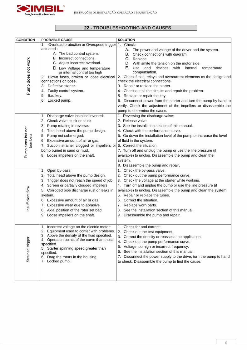
22 - TROUBLESHOOTING AND CAUSES
CONDITION PROBABLE CAUSE SOLUTION
1. Overload protection or Overspeed trigger actuated :
A. The bad control system.
B. Incorrect connections.
C. Adjust incorrect overload.
D. Low Voltage and temperature or internal control too high
2. Blown fuses, broken or loose electrical connections or loose. 3. Defective starter.
4. Faulty control system. 5. Bad key. 6. Locked pump.
1. Check:
A. The power and voltage of the driver and the system.
B. Check connections with diagram.
C. Replace.
D. With smite the tension on the motor side.
E. Use and devices with internal temperature compensation.
2. Check fuses, relays and overcurrent elements as the design and check the electrical connections. 3. Repair or replace the starter.
4. Check out all the circuits and repair the problem.
5. Replace or repair the key.
6. Disconnect power from the starter and turn the pump by hand to
verify. Check the adjustment of the impellers or disassemble the
pump to determine the cause.
1. Discharge valve installed inverted:
2. Check valve stuck or stuck.
3. Pump rotating in reverse.
4. Total head above the pump design.
5. Pump not submerged.
6. Excessive amount of air or gas.
7. Suction strainer clogged or impellers or
bomb buried in sand or mud.
8. Loose impellers on the shaft.
1. Reversing the discharge valve:
2. Release valve.
3. See the installation section of this manual.
4. Check with the performance curve.
5. Go down the installation level of the pump or increase the level
of fluid in the system.
6. Correct the situation.
7. Turn off and unplug the pump or use the line pressure (if
available) to unclog. Disassemble the pump and clean the
system.
8. Disassemble the pump and repair.
1. Open by-pass:
2. Total head above the pump design.
3. Trigger does not reach the speed of job.
4. Screen or partially clogged impellers.
5. Corroded pipe discharge rust or leaks in
system.
6. Excessive amount of air or gas.
7. Excessive wear due to abrasive.
8. Axial position of the rotor set bad.
9. Loose impellers on the shaft.
1. Check the by-pass valve:
2. Check out the pump performance curve.
3. Check the voltage at the starter while working.
4. Turn off and unplug the pump or use the line pressure (if
available) to unclog. Disassemble the pump and clean the system.
5. Repair or replace the tubes.
6. Correct the situation.
7. Replace worn parts.
8. See the installation section of this manual.
9. Disassemble the pump and repair.
1. Incorrect voltage on the electric motor: 2. Equipment used to confer with problems. 3. Above the density of the fluid specified. 4. Operation points of the curve than those specified. 5. Starter spinning speed greater than specified. 6. Drag the rotors in the housing. 7. Locked pump.
1. Check for and correct:
2. Check out the test equipment.
3. Correct the density or reassess the application.
4. Check out the pump performance curve.
5. Voltage too high or incorrect frequency.
6. See the installation section of this manual.
7. Disconnect the power supply to the drive, turn the pump to hand
to check. Disassemble the pump to find the cause.
INSTRUÇÕES DE INSTALAÇÃO, OPERAÇÃO E MANUTENÇÃO
7
23. 1 - Head Discharge
Make sure the valve is closed the lock extension of the pump. Disconnect the connection between the head and discharge pipe by loosening the screws and removing the flanges before proceeding with the disassembly.
Lift the pump with the use of slings , eyebolts and appropriate shackles . Attach one clamp disassembly just below the first flange union column between the top tube and the column tube. Support foundations in this clip and be sure to be firm , well supported before proceeding with the disassembly.
Remove the screws of the top tube to head . Lift the printhead by removing it from the docking top tube and proceed to spend per head on the upper end of the shaft.
Lay the head on a soft surface and clean as wood or cardboard, to avoid damage to sealing surfaces .
23.2 - Column Top
Remove the screws of the top tube to tube column. Remove the tube and hold the top metallic stabilizer in place temporarily .Then close the opening of the column to avoid possibility of falling parts or extraneous elements within the pump .
With the aid of two pipe wrenches , remove the protective tube top unscrewing clockwise because its thread is left. Put the two keys same side of the tube to avoid excessive strain on pipe or shaft. Ice it up to remove it over the tip of top shaft.
Then undo the coupling of the shafts with aid of pliers for removing locks , sliding lock up as much as possible and moving ring the following coupling up to rid the union . Remove the anchor ring separating the halves with blade of a screwdriver. The shaft can be removed.
23.3 - Column
Remove the metal stabilizer upper flange column. Lift the set pump and secure the clamp disassembly below the forthcoming marriage column .
Repeat the procedures described for the removal of above the top of the column .
Remove the lower column pipe , install a beam or clamp the pump body to support it during disassembly of the lower tube column.
23.4 - Body Pump
Lift body of the pump shaft. If the pump is equipped with a sieve , remove it before placing it anyway .
Place the pump body horizontal position for facilitate inspection and eventual disassembly of the same.
Beware this operation because the suction bell has delicate edges and can be damaged easily if the body is supported by the edge of the bell during the move.
24 – REPAIRS
Before proceeding with assembly , clean carefully all screws , nuts , connections and threaded mounting faces and apply a lubricant appropriate. Remove all burrs with a fine file or sandpaper.
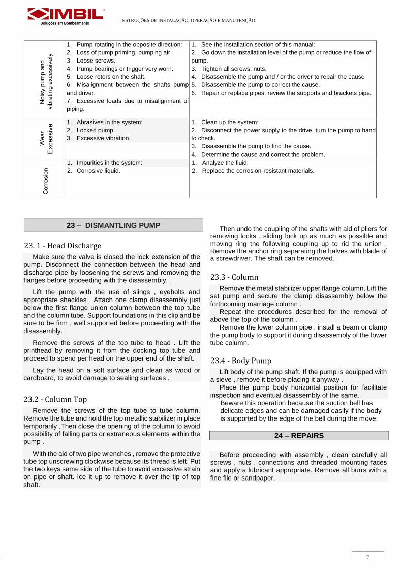
1. Pump rotating in the opposite direction:
2. Loss of pump priming, pumping air.
3. Loose screws.
4. Pump bearings or trigger very worn.
5. Loose rotors on the shaft.
6. Misalignment between the shafts pump
and driver.
7. Excessive loads due to misalignment of
piping.
1. See the installation section of this manual:
2. Go down the installation level of the pump or reduce the flow of
pump.
3. Tighten all screws, nuts.
4. Disassemble the pump and / or the driver to repair the cause
5. Disassemble the pump to correct the cause.
6. Repair or replace pipes; review the supports and brackets pipe.
1. Abrasives in the system:
2. Locked pump.
3. Excessive vibration.
1. Clean up the system:
2. Disconnect the power supply to the drive, turn the pump to hand
to check.
3. Disassemble the pump to find the cause.
4. Determine the cause and correct the problem.
1. Impurities in the system:
2. Corrosive liquid. 1. Analyze the fluid:
2. Replace the corrosion-resistant materials.
23 – DISMANTLING PUMP
INSTRUÇÕES DE INSTALAÇÃO, OPERAÇÃO E MANUTENÇÃO
8
NOTE:
Cleaning and proper lubrication are necessary to ensure ease of reassembly and operation appropriate.
NOTE:
Even if the shaft is new or has previously done straightened , it is recommended that this be checked at this point to ensure that no damage shipping or handling.
25 – BODY MOUNT
1. Insert the shaft into the suction bell . Adjustment of such so that the end of the shaft is aligned with the bottom of bearing the suction bell. 2. Install the key in the slot near the axis of the impeller is mounted. 3. Slide the impeller onto the shaft and the keyway and lay it on the suction bell or body. 4. Adjust the shaft in such a way that the tear key is under the impeller hub. 5. Enter the two halves of the ring anchor the groove of the impeller shaft. The recessed holes should be facing in the opposite direction to the impeller. 6. Align the holes in the anchor ring with the threads the impeller. Attach the ring with anchor bolts and press alike. 7. Slide the intermediate body in the spindle and into the suction bell or body. Rotate the body to align ribs with the suction bell and other bodies. 8. Install the screws tightening the body so and gradual cross. 9. Grab the shaft and rotate by hand to see if there is any obstruction. Check the axial travel the same way as before dismantling and compare with the measured value prior to disassembly. 10. Install the plug and tighten the suction bell. 11. Install the coupling shaft at the end of column. 12. Check tightness of all nuts and bolts.
26 – INSPECTION AND CLEANING
After disassembly , all components must be carefully cleaned and examined when the physical defects , wear, corrosion or damage .
CAUTION
When repairing a pump body that was in service for several years , and the physical conditions resistance of parts such as screws , bodies and threads of the bodies should be carefully evaluated before reuse these components
CAUTION
When rework is necessary in any part, should be alert to maintain alignment with the adjacent pieces and original tolerances.
26.1 - Impellers
Clean all hydraulic passages and examine for signs of damage from abrasion and corrosion. Replace any that show signs of impellers excessive wear.
26.2 - Bodies
Clean all hydraulic passages and examine for damage or wear by abrasion or corrosion. Replace all bodies that are experiencing straws broken or excessive wear .
26.3 - Shafts
Check shaft for wear, pitting and straightness . Damage to the shaft are usually corrected substitution
26.4 - Bearings
Check all bearings as the total clearance against the shaft. It is recommended that all bearings that exhibit wear visible are replaced.
Bearings are sized substitutes for cold be mounted in the housing so that the and the resulting tablets are internal dimension is within the desired tolerances.