Embed Size (px)
Citation preview

1 6 0 8 1 5 _ 2 0 3 8 _ 4 0 0 V
Installation, operation and careWall-mounted electric boiler
MP 6
Geel: Pantone 109 EC
Donker blauw: Pantone 539 EC
Lichtblauw: Pantone 544 EC
To be completed when the MP 6 is installed!
Serial number: ...................................................................................................................................................
Installation date: ...................................................................................................................................................
Installer: ...................................................................................................................................................
Tel: ...................................................................................................................................................
Other: ...................................................................................................................................................
...................................................................................................................................................
...................................................................................................................................................
...................................................................................................................................................
...................................................................................................................................................
...................................................................................................................................................
...................................................................................................................................................
...................................................................................................................................................
Notes
Contents
Notes ............................................................................... 2Safety and handling ....................................................... 3Operation ........................................................................ 4 Many possible uses Separate systems are better Compact Powerful Complete Accessories
Technical data ................................................................ 5Pipe installation .............................................................. 7 System principle Expansion vessel Safety valve Filling - bleeding Flow - bypass valve
Electrical installation ..................................................... 8 Power supply External block/room thermostat Wiring diagram
Operation and care ......................................................... 9 Control panel Temperature settings Safety valve Overheating protection If there is a risk of freezing Thermometer Expansion vessel Water pressure in the system Bleeding
Circulation pump ............................................................ 10Troubleshooting .............................................................. 11Components
2
3
Safety and handling
Read these instructions carefully before installation, adjustment or service is carried out.
Keep the instructions close to the boiler.
Check that the delivery is complete.
All installation must be performed by an authorised person in accordance with the existing regulations.
Only authorised persons may work on the system.
Correct installation in combination with cor-rect adjustment and continuous service will produce high operational reliability and good heating economy.
Use only original spare parts. Spare parts that do not meet Värmebaronen's specifica-tions may have an impact on safety.
Always contact your installation engineer for service. The type and serial number of the boiler must always be specified when ordering spare parts. See the rating plate.
The boiler must not be modified, changed or converted in any way.
Never disable the safety equipment!
Before service and maintenance work are started, the system must be disconnected from the main power supply.
This product is not designed to be used by persons with reduced physical or mental ca-pacity or a lack of experience and knowledge unless they are supervised or instructed by a person with responsibility for their safety. Children must be instructed/supervised to ensure that they never play with the product.
Värmebaronen AB reserves the right to change the specification, in accordance with its policy of continuous improvement and development, without prior notice.
Subject to amendments and printing and proofreading errors.
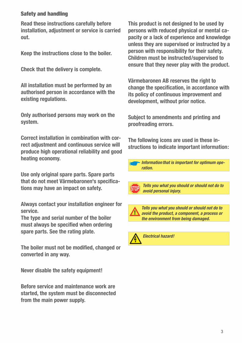
The following icons are used in these in-structions to indicate important information:
Information that is important for optimum ope-ration.
Tells you what you should or should not do to avoid personal injury.
Tells you what you should or should not do to avoid the product, a component, a process or the environment from being damaged.
Electrical hazard!
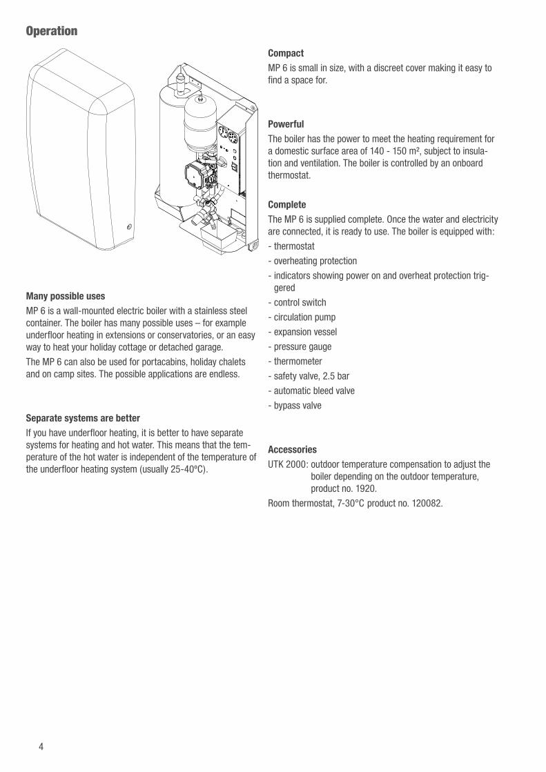
Many possible usesMP 6 is a wall-mounted electric boiler with a stainless steel container. The boiler has many possible uses – for example underfloor heating in extensions or conservatories, or an easy way to heat your holiday cottage or detached garage.
The MP 6 can also be used for portacabins, holiday chalets and on camp sites. The possible applications are endless.
Separate systems are betterIf you have underfloor heating, it is better to have separate systems for heating and hot water. This means that the tem-perature of the hot water is independent of the temperature of the underfloor heating system (usually 25-40ºC).
CompactMP 6 is small in size, with a discreet cover making it easy to find a space for.
PowerfulThe boiler has the power to meet the heating requirement for a domestic surface area of 140 - 150 m², subject to insula-tion and ventilation. The boiler is controlled by an onboard thermostat.
CompleteThe MP 6 is supplied complete. Once the water and electricity are connected, it is ready to use. The boiler is equipped with:
- thermostat
- overheating protection
- indicators showing power on and overheat protection trig-gered
- control switch
- circulation pump
- expansion vessel
- pressure gauge
- thermometer
- safety valve, 2.5 bar
- automatic bleed valve
- bypass valve
AccessoriesUTK 2000: outdoor temperature compensation to adjust the
boiler depending on the outdoor temperature, product no. 1920.
Room thermostat, 7-30°C product no. 120082.
Operation
4
5
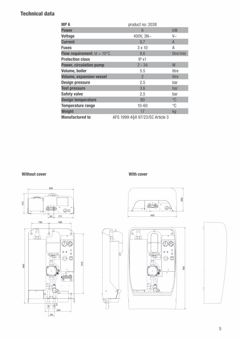
Without cover With cover
Technical data
200
700
420
150 189
224
515
173
392
17150
50
640
MP 6 product no: 2038Power 6 kWVoltage 400V, 3N~ V~Current 8,7 AFuses 3 x 10 AFlow requirement ∆t = 10°C. 8,6 litre/minProtection class IP x1Power, circulation pump 2 - 34 WVolume, boiler 5.5 litreVolume, expansion vessel 2 litreDesign pressure 2.5 barTest pressure 3.6 barSafety valve 2.5 barDesign temperature 80 °CTemperature range 10-60 °CWeight 17 kgManufactured to AFS 1999:4§8 97/23/EC Article 3

Technical data
5. Circulation pump
15. Flow pipe, R20 ext.
16. Return pipe, R20 ext.
17. Bypass with shut-off valves.
18. Safety valve.
19. Expansion vessel.
20. Bleed valve.
21. Stainless steel container, insulated, with immersion heater.
22. Protective cover for immersion heater wiring.
23. Cable openings.
24. Knock out for cables if they lead from the wall.
25. Collecting vessel, bleed water from safety valve.
26. Sensor clip, thermometer bulb.
27. Protective cover.
152416
5
21
22
23
25
17
18
19
20
26
27
6
7
The installation must comply with the applica-ble regulations and standards.
The boiler is designed for indoor use, fixed to the wall or similar support with the pipes connected underneath.The ambient temperature must not exceed 30°C.The clearance underneath the boiler must be at least 300 mm to allow the immersion heater to be changed if necessary.Hard water with a high mineral content is not suitable for HVAC applications.To avoid corrosion, the pH value should not be too low.The venting pipe from the boiler safety valve leads to a drip collector within the boiler.The applicable regulations state that an installation inspection must be carried out on a system with a sealed expansion vessel, before it is put into operation. The inspection must be carried out by a person qualified for the task. A further inspection is required if any parts or the expansion vessel are replaced.Clamps must be used when the connections are made to prevent damage to the internal pipework.
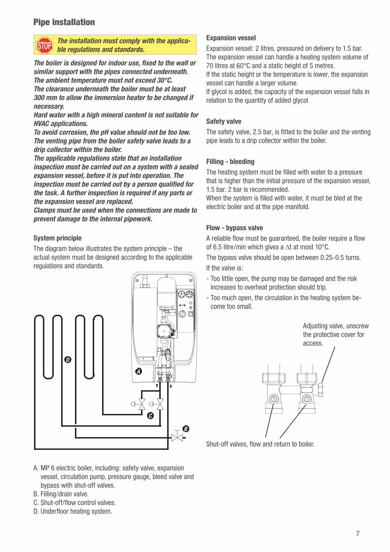
System principleThe diagram below illustrates the system principle – the actual system must be designed according to the applicable regulations and standards.
A
B
C
D
A. MP 6 electric boiler, including: safety valve, expansion vessel, circulation pump, pressure gauge, bleed valve and bypass with shut-off valves.
B. Filling/drain valve.C. Shut-off/flow control valves.D. Underfloor heating system.
Expansion vesselExpansion vessel: 2 litres, pressured on delivery to 1.5 bar. The expansion vessel can handle a heating system volume of 70 litres at 60°C and a static height of 5 metres. If the static height or the temperature is lower, the expansion vessel can handle a larger volume. If glycol is added, the capacity of the expansion vessel falls in relation to the quantity of added glycol.
Safety valveThe safety valve, 2.5 bar, is fitted to the boiler and the venting pipe leads to a drip collector within the boiler.
Filling - bleedingThe heating system must be filled with water to a pressure that is higher than the initial pressure of the expansion vessel, 1.5 bar. 2 bar is recommended. When the system is filled with water, it must be bled at the electric boiler and at the pipe manifold.
Flow - bypass valveA reliable flow must be guaranteed, the boiler require a flow of 6.5 litre/min which gives a ∆t at most 10°C.
The bypass valve should be open between 0.25-0.5 turns.
If the valve is:
- Too little open, the pump may be damaged and the risk increases to overheat protection should trip.
- Too much open, the circulation in the heating system be-come too small.
Shut-off valves, flow and return to boiler.
Adjusting valve, unscrew the protective cover for access.
Pipe installation
Electrical installation must be in accordance with the applicable regulations, under the supervision of an authorised installer.
The boiler must not be connected to the power supply before it is filled with water. An all-pole circuit breaker must be installed ahead of the boiler. The ambient temperature must not exceed 30°C.
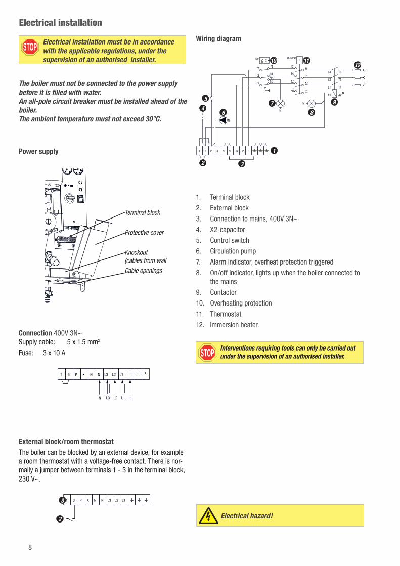
Power supply
Terminal block
Protective cover
Knockout (cables from wall
Cable openings
Connection 400V 3N~ Supply cable: 5 x 1.5 mm2
Fuse: 3 x 10 A
1 3 P X N N L3 L2 L1
N L3 L2 L1
External block/room thermostatThe boiler can be blocked by an external device, for example a room thermostat with a voltage-free contact. There is nor-mally a jumper between terminals 1 - 3 in the terminal block, 230 V~.
1 3 P X N N L3 L2 L13
2
Wiring diagram
1 3 P X N N L3 L2 L1
T3
T2
T1
L3
L2
L1
A2A1K1
11
12
21
22
31
32
41
42
0-60°CT
N
24
80°
31
32
21
22
11
12
S1
N
N
N
N
1
2
4
5
6
7
8
9
10 11
3
12
1. Terminal block
2. External block
3. Connection to mains, 400V 3N~
4. X2-capacitor
5. Control switch
6. Circulation pump
7. Alarm indicator, overheat protection triggered
8. On/off indicator, lights up when the boiler connected to the mains
9. Contactor
10. Overheating protection
11. Thermostat
12. Immersion heater.
Interventions requiring tools can only be carried out under the supervision of an authorised installer.
Electrical installation
Electrical hazard!
8
9
Control panel
Min. 0,5 BarMax. 2,5 Bar
Tillse att pannanär vattenfylld innan
den startas
Boiler must be filled with water
before start
°C
6
7 9
10
11
13 14
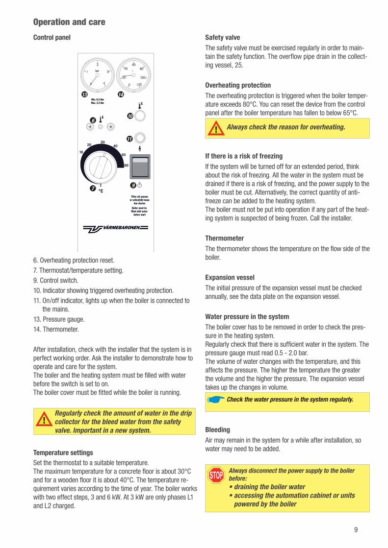
6. Overheating protection reset.7. Thermostat/temperature setting.9. Control switch.10. Indicator showing triggered overheating protection.11. On/off indicator, lights up when the boiler is connected to
the mains.13. Pressure gauge.14. Thermometer.
After installation, check with the installer that the system is in perfect working order. Ask the installer to demonstrate how to operate and care for the system. The boiler and the heating system must be filled with water before the switch is set to on. The boiler cover must be fitted while the boiler is running.
Regularly check the amount of water in the drip collector for the bleed water from the safety valve. Important in a new system.
Temperature settingsSet the thermostat to a suitable temperature. The maximum temperature for a concrete floor is about 30°C and for a wooden floor it is about 40°C. The temperature re-quirement varies according to the time of year. The boiler works with two effect steps, 3 and 6 kW. At 3 kW are only phases L1 and L2 charged.
Safety valveThe safety valve must be exercised regularly in order to main-tain the safety function. The overflow pipe drain in the collect-ing vessel, 25.
Overheating protectionThe overheating protection is triggered when the boiler temper-ature exceeds 80°C. You can reset the device from the control panel after the boiler temperature has fallen to below 65°C.
Always check the reason for overheating.
If there is a risk of freezingIf the system will be turned off for an extended period, think about the risk of freezing. All the water in the system must be drained if there is a risk of freezing, and the power supply to the boiler must be cut. Alternatively, the correct quantity of anti-freeze can be added to the heating system. The boiler must not be put into operation if any part of the heat-ing system is suspected of being frozen. Call the installer.
ThermometerThe thermometer shows the temperature on the flow side of the boiler.
Expansion vesselThe initial pressure of the expansion vessel must be checked annually, see the data plate on the expansion vessel.
Water pressure in the systemThe boiler cover has to be removed in order to check the pres-sure in the heating system. Regularly check that there is sufficient water in the system. The pressure gauge must read 0.5 - 2.0 bar. The volume of water changes with the temperature, and this affects the pressure. The higher the temperature the greater the volume and the higher the pressure. The expansion vessel takes up the changes in volume.
Check the water pressure in the system regularly.
BleedingAir may remain in the system for a while after installation, so water may need to be added.
Always disconnect the power supply to the boiler before: • draining the boiler water • accessing the automation cabinet or units
powered by the boiler
Operation and care
Circulation pumpDelivery setting: Constant pressure curve 1.
If parts of the heating system does not get hot, this may need to be changed to Constant pressure curve 2. Election of a higher curve increases energy consumption and operating cost.
Push bottom LED indications
When the pump is running, LED 1 is green. The four yellow LEDs indicate the current power consumption as shown below.
0 - 25 %
25 - 50 %
50 - 75 %
75 - 100 %
Pressing the push button shows which mode controls the pump. After 2 seconds, the display switches back to perfor-mance view.
PROP. PRESS.: CURVE 1
PROP. PRESS.: CURVE 2
PROP. PRESS.: CURVE 3
CONST. PRESS.: CURVE 1
CONST. PRESS.: CURVE 2
CONST. PRESS.: CURVE 3
CONST. CURVE: CURVE 1
CONST. CURVE: CURVE 2
CONST. CURVE: CURVE 3
CONST. CURVE: CURVE 4
Pressing the button for 2 seconds switches to "setting selection". You can change the settings as they appear. The settings appear in a particular order in a closed loop. When releaseing the button, the user interface switches back to the performance view and the last setting is stored.
Circulation pump
If LED 1 is red, it indicates alarm or warning.
Display Indication Pump opera-tion
Counter action
Red +
one yellow
Rotor is blocked.
Trying to startagain every 1.5
Wait or deblockthe shaft.
Red +
one yellow
Supply volt-age too low.
Only warning, pump runs.
Control the supply voltage.
Red +
one yellow (LED 3)
Electrical error.
Pump is stopped be-cause of low supply voltage or serious failure.
Control the supply voltage /Exchange the pump.
Key lock functionIf you press the key lock for more than 10 seconds, you can toggle between enabling/disabling the key lock function. When doing so, all LEDs, except for the red LED, will flash for a second indicating that lock is toggled.
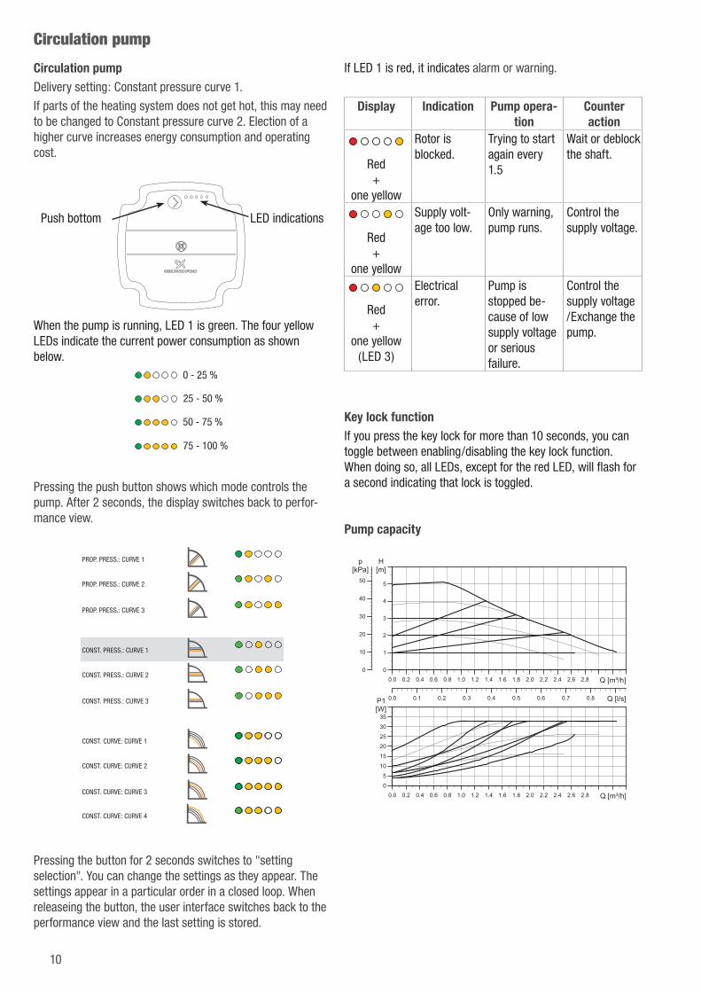
Pump capacity
0
1
2
3
4
0.0 0.2 0.4 0.6 0.8 1.0 1.2 1.4 1.6 1.8 2.0 2.2 2.4 2.6 2.8 Q [m³/h]
5
[m]H
0
10
20
30
40
50
[kPa]p
0.0 0.1 0.2 0.3 0.4 0.5 0.6 0.7 0.8 Q [l/s]
0
5
10
15
20
0.0 0.2 0.4 0.6 0.8 1.0 1.2 1.4 1.6 1.8 2.0 2.2 2.4 2.6 2.8 Q [m³/h]
25
30
35[W]P1
10

11
Troubleshooting
Problem Possible cause Solution
On/off indicator off, no heat in heating system.
No power to electric boiler. Check the fuses.
Switch set to off. Check that the main and control switch are set to on.
Boiler externally blocked. Check whether the immersion heater is being blocked by an external block/room thermostat.
Alarm indicator on. Overheating protection triggered. If the overheating protection is triggered, you must check the operation of the circulation pump and valves. To reset, press the button on the overheating protection after the boiler temperature has fallen below 65°C.
Always check the reason why the overheating protec-tion triggered – call the installer.
No heat or not enough heat. The valves in the heating system or boiler thermostat are set too low.
Check and adjust.
Incorrectly adjusted bypass valve.
Check and adjust.
Group fuses for the boiler triggered.
Immersion heater faulty. Check the immersion heater by doing an insulation test. Take measurements between the outgoing side of the contactor and earth. Call the installer.
Interventions requiring tools can only be carried out under the supervision of an authorised installer.
Components12 110015 Immersion heater 6 kW 1
300017 O-ring, immersion heater 1
245078 Bleed valve 1
245115 H-bypass 1
245524 Safety valve 2.5 bar 1
6 246003 Cirkulation pump 1
246221 Expansion vessel 1
13 380009 Pressure gauge, 0-4 bar 1
440306 Panel overlay 1
710975 Container 1
720259 Cover 1
Components in electric cabinet
11 120026 Thermostat 1 120009 Thermostat knob 1
10 120028 Overheating protection 1
5 130032 Switch 1
9 170046 Contactor 1
8 190005 Lamp, orange 1
7 190006 Lamp, red 1
14 380022 Thermometer 1
4 440090 X2-capacitor 1

MasterwattReeweg 132
3343 AP Hendrik-Ido-AmbachtT: +31 (0)85 - 303 7450
Geel: Pantone 109 EC
Donker blauw: Pantone 539 EC
Lichtblauw: Pantone 544 EC


![Pillar and wall-mounted slewing jib cranes · Max. load capacity [kg] Electric slewing Pillar-mounted slewing jib cranes Wall-mounted slewing jib cranes Jib type/design Max. outreach](https://img.pdfslide.us/doc/110x75/5b535fa87f8b9ae30b8be93d/pillar-and-wall-mounted-slewing-jib-cranes-max-load-capacity-kg-electric.jpg)