Embed Size (px)
Citation preview
HAYWARD®
Installation, Operation & Service ProceduresPool and Spa/Hot Tub Heaters
Models H250IDL2, H350IDL2 & H400IDL2
PATENT NO. 6026804 1303026201 1105
FOR YOUR SAFETY
– Do not store or use gasoline or other flam-mable vapors or liquids in the vicinity of thisor any other appliance.
WHAT TO DO IF YOU SMELL GAS• Do not try to light any appliance• Do not touch any electrical switch; do not
use any phone in your building• Immediately call your gas supplier from a
neighbor’s phone. Follow the gas suppli-er’s instructions.
• If you cannot reach your gas supplier, callthe fire department.
– Installation and service must be performedby a qualified installer, service agency or thegas supplier.
WARNING: If the information in theseinstructions is not followed exactly, a fire orexplosion may result causing property dam-age, personal injury, or death.
FOR YOUR SAFETY
This product must be installed and serviced by authorized personnel, qualified inpool/spa heater installation. Improper installation and/or operation can create carbonmonoxide gas and flue gases that can cause serious injury, property damage, or death.
For indoor installations, as an additional measure of safety, Hayward strongly recom-mends installation of suitable Carbon Monoxide (CO) detectors in the vicinity of this appli-ance and in any adjacent occupied spaces. Improper installation and/or operation willvoid the warranty.
Section I. General InformationIntroduction:
This manual contains instructions for installation,operation, maintenance, troubleshooting and partslists for the safe use of the Model H250IDL, H350IDLand H400IDL Low NOx swimming pool/spa/hot tubheaters.
Hayward strongly recommends that the manual beread by the installer before installing the swimmingpool/spa/hot tub heater. If after reviewing the manual,any questions still remain unanswered, contact thefactory or local representative. Following heaterinstallation, the installer should leave the manual withthe consumer for future reference.
Hayward heaters:The H-Series gas-fired pool/spa heater is the
result of nearly 50 years in the engineering and pro-duction of the finest water heating equipment. Thedirect fired finned-tube design of the pool/spa heatersis the most advanced in the industry, offering highlyefficient, economical pool/spa heating and scale freeoperation. No effort has been spared in making themost rugged, highly dependable, easy-to-maintainpool/spa heater available.
The H-Series heaters are suitable only for heatingof swimming pools, spas, or hot tubs. These heatersshould not be used as space heating boilers, generalpurpose water heaters, or for heating salt water poolsand fish ponds. When installed and operated in accor-dance with the manual’s instructions, the H-Seriesheater will provide many years of trouble free serviceand increased pool/spa enjoyment.
Limited warranty summary:We warrant the H-Series pool/spa heater to be
free from defects in materials and workmanship, andwe will within one year from date of installation for allusers, for the original purchaser, repair or, at ouroption, replace without charge any defective part.
We further warrant that if the heat exchanger orexchanger headers (water-containing section) leakwithin one year from date of such installation for allusers, due to defects in materials and workmanship,we will provide a replacement part.
Under the terms of the special FireTile™ limitedwarranty, we will replace any FireTile™ componentsused in the combustion chamber of the pool/spaheater which fail from defects in the workmanship andmaterials under normal use and service in a singlefamily residential application for a period of (5) years.
Cost of freight, installation, fuel, and service labor(after one year) is at user’s expense. For full detailsof warranty agreement, see warranty certificateincluded in this manual.
CAUTION: If the pool/spa heater is damaged ordestroyed by improper maintenance, excessivewater hardness, incorrect water chemistry, orfreezing it is not covered under the manufactur-er’s warranty.
3
ContentsSECTION I. GENERAL INFORMATION . . . . . . . . . . . . . . . . . . . . . . . . . . . .3
Introduction . . . . . . . . . . . . . . . . . . . . . . . . . . . . . . . . .3Hayward heaters . . . . . . . . . . . . . . . . . . . . . . . . . . . .3Warranty . . . . . . . . . . . . . . . . . . . . . . . . . . . . . . . . . . .3
SECTION II. HEATER SIZING . . . . . . . . . . . . . . . . . . . . . . . . . . . . . . . . . . .4
Selecting the correct size heater . . . . . . . . . . . . . . . .4For a swimming pool . . . . . . . . . . . . . . . . . . . . . . . . .4For a spa or hot tub . . . . . . . . . . . . . . . . . . . . . . . . . .4
SECTION III. INSTALLATION . . . . . . . . . . . . . . . . . . . . . . . . . . . . . . . . . . . .5
Equipment inspection . . . . . . . . . . . . . . . . . . . . . . . . .5Important notice . . . . . . . . . . . . . . . . . . . . . . . . . . . . .5Conformance with codes . . . . . . . . . . . . . . . . . . . . . .5Sea Level/high altitude installation . . . . . . . . . . . . . . .5Location of Heater . . . . . . . . . . . . . . . . . . . . . . . . . . .5Flooring . . . . . . . . . . . . . . . . . . . . . . . . . . . . . . . . . . .5Reversible water connections . . . . . . . . . . . . . . . . . .5Outdoor installation and venting . . . . . . . . . . . . . . . . .6Indoor installation and venting . . . . . . . . . . . . . . . . . .7Air supply . . . . . . . . . . . . . . . . . . . . . . . . . . . . . . . . . .7Equipment located in confined spaces . . . . . . . . . . .7Vertical Venting—Negative Pressure . . . . . . . . . . . . .8Indoor Adapter Kit Installation . . . . . . . . . . . . . . . . . .8Vent Sizing Table . . . . . . . . . . . . . . . . . . . . . . . . . . . .9Horizontal or Vertical Venting-Positive Pressure . . . . . .10Special Gas Vent Adapter Kit Installation . . . . . . . . .10Indoor Installation . . . . . . . . . . . . . . . . . . . . . . . . . . .11Connecting Special Gas Vent to the Heater . . . . . .11Gas supply and piping . . . . . . . . . . . . . . . . . . . . . . .12All gas installations . . . . . . . . . . . . . . . . . . . . . . . . . .13Water piping . . . . . . . . . . . . . . . . . . . . . . . . . . . . . . .13Installation above pool/spa surface . . . . . . . . . . . . .16Automatic chlorinators and chemical feeders . . . . .16Pressure relief valve . . . . . . . . . . . . . . . . . . . . . . . . .16Electrical connections . . . . . . . . . . . . . . . . . . . . . . . .17Remote control connection . . . . . . . . . . . . . . . . . . .18Remote thermostat connection . . . . . . . . . . . . . . . .18Connecting a remote . . . . . . . . . . . . . . . . . . . . . . . .182-Wire remote thermostat . . . . . . . . . . . . . . . . . . . .182-Wire Remote Switch . . . . . . . . . . . . . . . . . . . . . . .183-Wire Remote Switch . . . . . . . . . . . . . . . . . . . . . . .18
SECTION IV. INSTALLER CHECK-OUT AND START-UP . . . . . . . . . . . . . . .20
General . . . . . . . . . . . . . . . . . . . . . . . . . . . . . . . . . . .20Gas line testing . . . . . . . . . . . . . . . . . . . . . . . . . . . .20Gas pressure test procedure . . . . . . . . . . . . . . . . . .20Installation below pool/spa surface . . . . . . . . . . . . .22Two speed pump . . . . . . . . . . . . . . . . . . . . . . . . . . .22
SECTION V. CONSUMER OPERATION & MAINTENANCE PROCEDURES . . . . .23
General . . . . . . . . . . . . . . . . . . . . . . . . . . . . . . . . . . .23Pool/Spa water chemistry . . . . . . . . . . . . . . . . . . . .23Using chlorinators and chemical feeders . . . . . . . . .23Heater operation . . . . . . . . . . . . . . . . . . . . . . . . . . . .23Operating Instructions . . . . . . . . . . . . . . . . . . . . . . .24Temperature control operation . . . . . . . . . . . . . . . . .25Set point adjustment . . . . . . . . . . . . . . . . . . . . . . . .25Periodic inspection . . . . . . . . . . . . . . . . . . . . . . . . . .26Winterization . . . . . . . . . . . . . . . . . . . . . . . . . . . . . . .26Opening drain valve . . . . . . . . . . . . . . . . . . . . . . . . .27Spring start-up . . . . . . . . . . . . . . . . . . . . . . . . . . . . .27
SECTION VI. QUALIFIED TECHNICIAN – MAINTENANCE/SERVICING . . . .28
General . . . . . . . . . . . . . . . . . . . . . . . . . . . . . . . . . . .28Maintenance . . . . . . . . . . . . . . . . . . . . . . . . . . . . . . .28Control Access . . . . . . . . . . . . . . . . . . . . . . . . . . . . .28External heat exchanger inspection and cleaning . .28Heat exchanger removal . . . . . . . . . . . . . . . . . . . . .29Combustion chamber . . . . . . . . . . . . . . . . . . . . . . . .29Burner inspection and cleaning . . . . . . . . . . . . . . . .30Burner removal . . . . . . . . . . . . . . . . . . . . . . . . . . . . .30Burner Installation . . . . . . . . . . . . . . . . . . . . . . . . . .30Gas valve replacement . . . . . . . . . . . . . . . . . . . . . .30Ignitor removal . . . . . . . . . . . . . . . . . . . . . . . . . . . . .31Main burner orifices . . . . . . . . . . . . . . . . . . . . . . . . .31Gas conversion . . . . . . . . . . . . . . . . . . . . . . . . . . . .31Control Locations . . . . . . . . . . . . . . . . . . . . . . . . . . .31Electrical Wiring . . . . . . . . . . . . . . . . . . . . . . . . . . . .31Temperature controls . . . . . . . . . . . . . . . . . . . . . . . .31Vent Pressure switch . . . . . . . . . . . . . . . . . . . . . . . .31High limits . . . . . . . . . . . . . . . . . . . . . . . . . . . . . . . . .32Blower vacuum switch . . . . . . . . . . . . . . . . . . . . . . .32Water pressure switch . . . . . . . . . . . . . . . . . . . . . . .33Thermistor . . . . . . . . . . . . . . . . . . . . . . . . . . . . . . . .33By-pass valve . . . . . . . . . . . . . . . . . . . . . . . . . . . . . .34Thermal control valve . . . . . . . . . . . . . . . . . . . . . . . .34Transformer . . . . . . . . . . . . . . . . . . . . . . . . . . . . . . .35Combustion blower . . . . . . . . . . . . . . . . . . . . . . . . . .35
SECTION VII. TROUBLESHOOTING . . . . . . . . . . . . . . . . . . . . . . . . . . .36-39
PARTS LIST . . . . . . . . . . . . . . . . . . . . . . . . . . . . . . . . . . . . . . . . . . . . . .40
PARTS ILLLUSTRATION . . . . . . . . . . . . . . . . . . . . . . . . . . . . . . . . . . . . . . .41
WARRANTY & WARRANTY CARD . . . . . . . . . . . . . . . . . . . . . . . . . . . . . . 42-43
2
Section III. InstallationEquipment inspection:
On receipt of the heater equipment, inspect theheater carton for damage. If any carton is damaged,note it when signing for it. Remove the equipmentfrom the carton(s) and advise the carrier of any dam-ages at once.
Important notice:The instructions herein are intended for the use of
a qualified technician, specifically trained and experi-enced in the installation of this type of heating equip-ment. Some states or provinces require that installa-tion be licensed. If this is the case in the state orprovince where heater is located, the contractor mustbe properly licensed.
WARNING: Failure to comply with the appli-ance and vent package installation instructionsand service instructions in this manual may resultin equipment damage, fire, asphyxiation, or car-bon monoxide poisoning. Exposure to productsof incomplete combustion (carbon monoxide) cancause cancer and birth defects or other reproduc-tive harm.
Conformance with codes:The heater shall be installed in accordance with all
local and state codes. The heater installation mustconform to the National Gas Code ANSI Z223.1 (lat-est edition) and with the requirements of the authorityhaving jurisdiction. Design Certification of the heateris in compliance with ANSI Z21.56•CSA4.7.
For Canadian installations, the heater is to beinstalled in accordance with the standards CAN/CGAB149.1 and B149.2 – INSTALLATION CODES FORGAS BURNING APPLIANCES AND EQUIPMENTand/or Local Codes, and if applicable, Standard CSAC22.1 – CANADIAN ELECTRICAL CODE, Part 1.
Sea Level/high altitude installation:The H-Series heaters may be installed up to 2,000
feet of elevation above sea level.
Location of heater:Locate the pool/spa heater in an area where leak-
age of heat exchanger or connections will not resultin damage to the area adjacent to the heater or to thestructure. When such locations cannot be avoided, itrecommended that a suitable drain pan, with drainoutlet, be installed under the heater. The pan mustnot restrict air flow.
This heater must be installed at least five feet fromthe inside wall of a pool/spa unless separated fromthe pool/spa by a solid barrier. This heater must beinstalled also at least five feet from the wall of anabove-ground pool.
The heater must be installed such that the locationof the vent assembly outlet relative to adjacent public
walkways, adjacent buildings, openable windows, andbuilding openings complies with the National FuelGas Code, ANSI Z223.1 and/or CAN/CGA B149Installation Codes.
Flooring:This heater can be installed on combustible flooring.
Reversible water connections:This heater is designed so that it can be installed
with the water connections located on either the rightor left side. Heaters are shipped from the factory withthe water connections on the right side. To bring thewater connections to the left side, follow step-by-stepinstructions below and refer to the illustration inFigure 5. These procedures should be performed bya trained service technician before the heater isinstalled.
1. Remove four (hot) vent screws and remove panel.
2. Remove heater top.3. Remove screws from left and right side
access panels. Remove panels.4. Remove the front panel.5. Disconnect high limit wires and reroute them
to opposite side of heater. Disconnect the thermistor leads from control panel and pull through intermediate panel.
6. Remove pressure switch and tube.7. Remove 12 nuts retaining front header and
carefully remove header.CAUTION: By-pass and thermal governor may
become dislodged when removing front heater. Theymust be reinstalled properly prior to reinstallation offront header.
CAUTION: Header O-ring may be re-used if notpermanently deformed. if installing new O-rings,Jack’s 327 Lube may be liberally applied to O-ring tokeep it in place during header installation.
8. Remove four screws retaining air deflector, and remove air deflector.
9. Unplug wires and pressure tap tubes from combustion blower.
10. Remove screws retaining flue collector and remove flue collector/combustion blower assembly.
11. Remove screws securing heat exchanger from tube sheets on both front and rear ofheater.
5
Section II. Heater SizingSelecting the correct size heater:
Factors influencing heater sizing include pool/spasize, average wind velocity, ambient temperature, anddesired increase in temperature over ambient temper-ature, and desired increase in temperature over ambi-ent. A pool/spa in a warm area with little or no windwill not require as large a heater as one in a coolwindy location. Detailed sizing information is providedbelow.
For a swimming pool:1. Determine pool’s surface area in square feet.
For indoor pool installations divide the pool’s surface area by 3.
2. Determine desired pool water temperature (usually 78 - 82º F).
3. Determine average air temperature of coldestmonth of use.
4. The temperature rise is difference between 2 & 3.
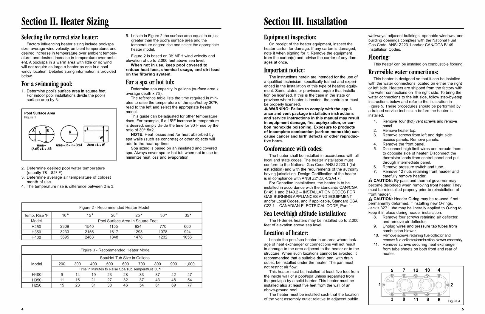
5. Locate in Figure 2 the surface area equal to or justgreater than the pool’s surface area and the temperature degree rise and select the appropriate heater model.Figure 2 is based on 31⁄2 MPH wind velocity and
elevation of up to 2,000 feet above sea level.When not in use, keep pool covered to
reduce heat loss, chemical usage, and dirt loadon the filtering system.
For a spa or hot tub:Determine spa capacity in gallons (surface area x
average depth x 71⁄2).The reference table lists the time required in min-
utes to raise the temperature of the spa/hot by 30ºF,read to the left and select the appropriate heatermodel.
This guide can be adjusted for other temperaturerises. For example, if a 15ºF increase in temperatureis desired, simply divide the time for 30ºF rise by theratio of 30/15=2.
NOTE: Heat losses and /or heat absorbed byspa walls (such as concrete) or other objects willadd to the heat-up time.
Spa sizing is based on an insulated and coveredspa. Always cover spa or hot tub when not in use tominimize heat loss and evaporation.
4
Temp. Rise FModel
H250
25 3015 2010 35
2309 1540 1155 924 770 660
H400 3695 2463 1848 1478 1232 1056H350 3233 2156 1617 1293 1078 924
Pool Surface Area In Square Feet
Figure 2 - Recommended Heater Model
Model
H400
Figure 3 - Recommended Heater Model
Spa/Hot Tub Size in Gallons
Time in Minutes to Raise Spa/Tub Temperature 30 F
200 300 400 500 600 700 800 900 1,000
9 14 19 23 28 33 37 42 47
H250 15 23 31 38 46 54 61 69 77H350 11 16 21 27 32 37 43 48 54
1
5 7 12 10 4
2
681193
Pool Surface AreaFigure 1
Figure 4
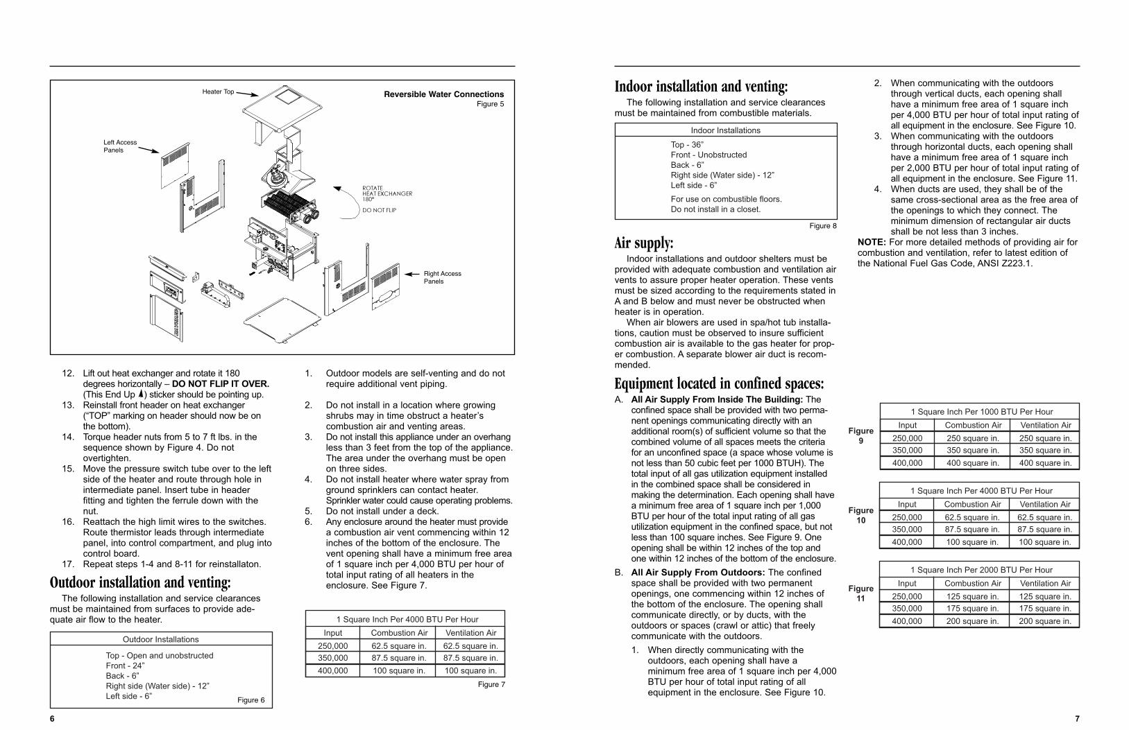
Indoor installation and venting:The following installation and service clearances
must be maintained from combustible materials.
Air supply:Indoor installations and outdoor shelters must be
provided with adequate combustion and ventilation airvents to assure proper heater operation. These ventsmust be sized according to the requirements stated inA and B below and must never be obstructed whenheater is in operation.
When air blowers are used in spa/hot tub installa-tions, caution must be observed to insure sufficientcombustion air is available to the gas heater for prop-er combustion. A separate blower air duct is recom-mended.
Equipment located in confined spaces:A. All Air Supply From Inside The Building: The
confined space shall be provided with two perma-nent openings communicating directly with an additional room(s) of sufficient volume so that the combined volume of all spaces meets the criteria for an unconfined space (a space whose volume is not less than 50 cubic feet per 1000 BTUH). The total input of all gas utilization equipment installed in the combined space shall be considered in making the determination. Each opening shall havea minimum free area of 1 square inch per 1,000 BTU per hour of the total input rating of all gas utilization equipment in the confined space, but not less than 100 square inches. See Figure 9. One opening shall be within 12 inches of the top and one within 12 inches of the bottom of the enclosure.
B. All Air Supply From Outdoors: The confined space shall be provided with two permanent openings, one commencing within 12 inches of the bottom of the enclosure. The opening shall communicate directly, or by ducts, with the outdoors or spaces (crawl or attic) that freely communicate with the outdoors.1. When directly communicating with the
outdoors, each opening shall have a minimum free area of 1 square inch per 4,000BTU per hour of total input rating of all equipment in the enclosure. See Figure 10.
2. When communicating with the outdoors through vertical ducts, each opening shall have a minimum free area of 1 square inch per 4,000 BTU per hour of total input rating ofall equipment in the enclosure. See Figure 10.
3. When communicating with the outdoors through horizontal ducts, each opening shall have a minimum free area of 1 square inch per 2,000 BTU per hour of total input rating ofall equipment in the enclosure. See Figure 11.
4. When ducts are used, they shall be of the same cross-sectional area as the free area ofthe openings to which they connect. The minimum dimension of rectangular air ducts shall be not less than 3 inches.
NOTE: For more detailed methods of providing air for combustion and ventilation, refer to latest edition ofthe National Fuel Gas Code, ANSI Z223.1.
7
12. Lift out heat exchanger and rotate it 180 degrees horizontally – DO NOT FLIP IT OVER.(This End Up ) sticker should be pointing up.
13. Reinstall front header on heat exchanger (“TOP” marking on header should now be on the bottom).
14. Torque header nuts from 5 to 7 ft lbs. in the sequence shown by Figure 4. Do not overtighten.
15. Move the pressure switch tube over to the leftside of the heater and route through hole in intermediate panel. Insert tube in header fitting and tighten the ferrule down with thenut.
16. Reattach the high limit wires to the switches. Route thermistor leads through intermediate panel, into control compartment, and plug intocontrol board.
17. Repeat steps 1-4 and 8-11 for reinstallaton.
Outdoor installation and venting:The following installation and service clearances
must be maintained from surfaces to provide ade-quate air flow to the heater.
1. Outdoor models are self-venting and do not require additional vent piping.
2. Do not install in a location where growing shrubs may in time obstruct a heater’s combustion air and venting areas.
3. Do not install this appliance under an overhangless than 3 feet from the top of the appliance.The area under the overhang must be open on three sides.
4. Do not install heater where water spray from ground sprinklers can contact heater. Sprinkler water could cause operating problems.
5. Do not install under a deck.6. Any enclosure around the heater must provide
a combustion air vent commencing within 12 inches of the bottom of the enclosure. The vent opening shall have a minimum free area of 1 square inch per 4,000 BTU per hour of total input rating of all heaters in the enclosure. See Figure 7.
6
ROTATEHEAT EXCHANGER180°
DO NOT FLIP
Outdoor Installations
Top - Open and unobstructedFront - 24”Back - 6”Right side (Water side) - 12”Left side - 6”
1 Square Inch Per 4000 BTU Per Hour
Input Combustion Air Ventilation Air
250,000
350,000
400,000
62.5 square in.
87.5 square in.
100 square in.
62.5 square in.
87.5 square in.
100 square in.
Indoor Installations
Top - 36”Front - UnobstructedBack - 6”Right side (Water side) - 12”Left side - 6”
For use on combustible floors.Do not install in a closet.
1 Square Inch Per 4000 BTU Per Hour
Input Combustion Air Ventilation Air
250,000
350,000
400,000
62.5 square in.
87.5 square in.
100 square in.
62.5 square in.
87.5 square in.
100 square in.
Figure10
1 Square Inch Per 2000 BTU Per Hour
Input Combustion Air Ventilation Air
250,000
350,000
400,000
125 square in.
175 square in.
200 square in.
125 square in.
175 square in.
200 square in.
Figure11
1 Square Inch Per 1000 BTU Per Hour
Input Combustion Air Ventilation Air
250,000
350,000
400,000
250 square in.
350 square in.
400 square in.
250 square in.
350 square in.
400 square in.
Figure9
Reversible Water ConnectionsFigure 5
Figure 6
Figure 7
Figure 8
Left AccessPanels
Right AccessPanels
Heater Top
9
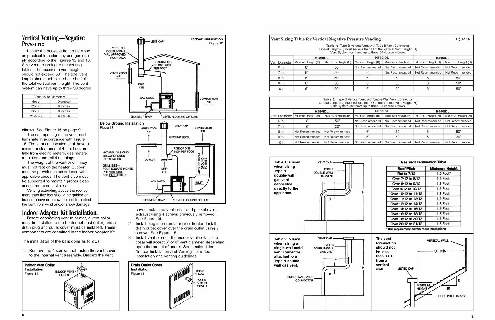
Vertical Venting—NegativePressure:
Locate the pool/spa heater as closeas practical to a chimney and gas sup-ply according to the Figures 12 and 13.Size vent according to the ventingtables. The maximum vent heightshould not exceed 50’. The total ventlength should not exceed one half ofthe total vertical vent height. The ventsystem can have up to three 90 degree
elbows. See Figure 16 on page 9.The cap opening of the vent must
terminate in accordance with Figure16. The vent cap location shall have aminimum clearance of 4 feet horizon-tally from electric meters, gas metersregulators and relief openings.
The weight of the vent or chimneymust not rest on the heater. Supportmust be provided in accordance withapplicable codes. The vent pipe mustbe supported to maintain proper clear-ances from combustibles.
Venting extending above the roof bymore than five feet should be guided orbraced above or below the roof to protectthe vent from wind and/or snow damage.
Indoor Adapter Kit Installation:Before connecting vent to heater, a vent collar
must be installed to the heater exhaust outlet, and adrain plug and outlet cover must be installed. Thesecomponents are contained in the indoor Adapter Kit.
The installation of the kit is done as follows:
1. Remove the 4 screws that fasten the vent cover to the internal vent assembly. Discard the vent
cover. Install the vent collar and gasket over exhaust using 4 screws previously removed. See Figure 14.
2. Install plug into drain at rear of heater. Install drain outlet cover over the drain outlet using 2 screws. See Figure 15.
3. Install vent pipe on the indoor vent collar. The collar will accept 6” or 8” vent diameter, dependingupon the model of heater. See section titled “Indoor Installation and Venting” for indoor installation and venting guidelines.
8
Vent Collar Diameters
Model Diameter
H250IDL
H350IDL
H400IDL
6 inches
8 inches
8 inches
Vent Diameter
6 in.
7 in.
8 in.
9 in.
10 in.
H250IDL H350IDL H400IDL
Vent Sizing Table for Vertical Negative Pressure Vending
Minimum Height (H) Maximum Hieight (H) Minimum Height (H) Maximum Hieight (H) Minimum Height (H) Maximum Hieight (H)
Table 1: Type B Vertical Vent with Type B Vent ConnectorLateral Length (L) must be less than Ω of the Vertical Vent Height (H)
Vent System can have up to three 90 degree elbows.
F
8'6'
6'
6' 6'
6'
6'
6'
6'
6'
6'
6'50' 50'
50'50'
50'
50'
50'
50' 50'
50'
Not RecommendedNot Recommended
Not Recommended Not Recommended
Not Recommended
Not Recommended
Not Recommended
50'
Vent Diameter
6 in.
7 in.
8 in.
9 in.
10 in.
H250IDL H350IDL H400IDLMinimum Height (H) Maximum Hieight (H) Minimum Height (H) Maximum Hieight (H) Minimum Height (H) Maximum Hieight (H)
Table 2: Type B Vertical Vent with Single Wall Vent ConnectorLateral Length (L) must be less than Ω of the Vertical Vent Height (H)
Vent System can have up to three 90 degree elbows.
8'
6'
6'6'6'
6'
50'
20'50'30' 30'
Not RecommendedNot Recommended
Not Recommended Not Recommended
Not Recommended
Not Recommended
Not Recommended
50'
Not Recommended Not Recommended Not RecommendedNot RecommendedNot RecommendedNot Recommended
Not Recommended
Not RecommendedNot Recommended
Not RecommendedNot Recommended
Figure 16Indoor InstallationFigure 12
Below Ground InstallationFigure 13
Indoor Vent CollarInstallationFigure 14
Drain Outlet CoverInstallationFigure 15
Table 1 is usedwhen sizingType Bdouble-wallgas ventconnecteddirectly to theappliance.
The ventterminationshould notbe lessthan 8 FT.from averticalwall.
Table 2 is usedwhen sizing asingle-wall metalvent connectorattached to a Type B double-wall gas vent.
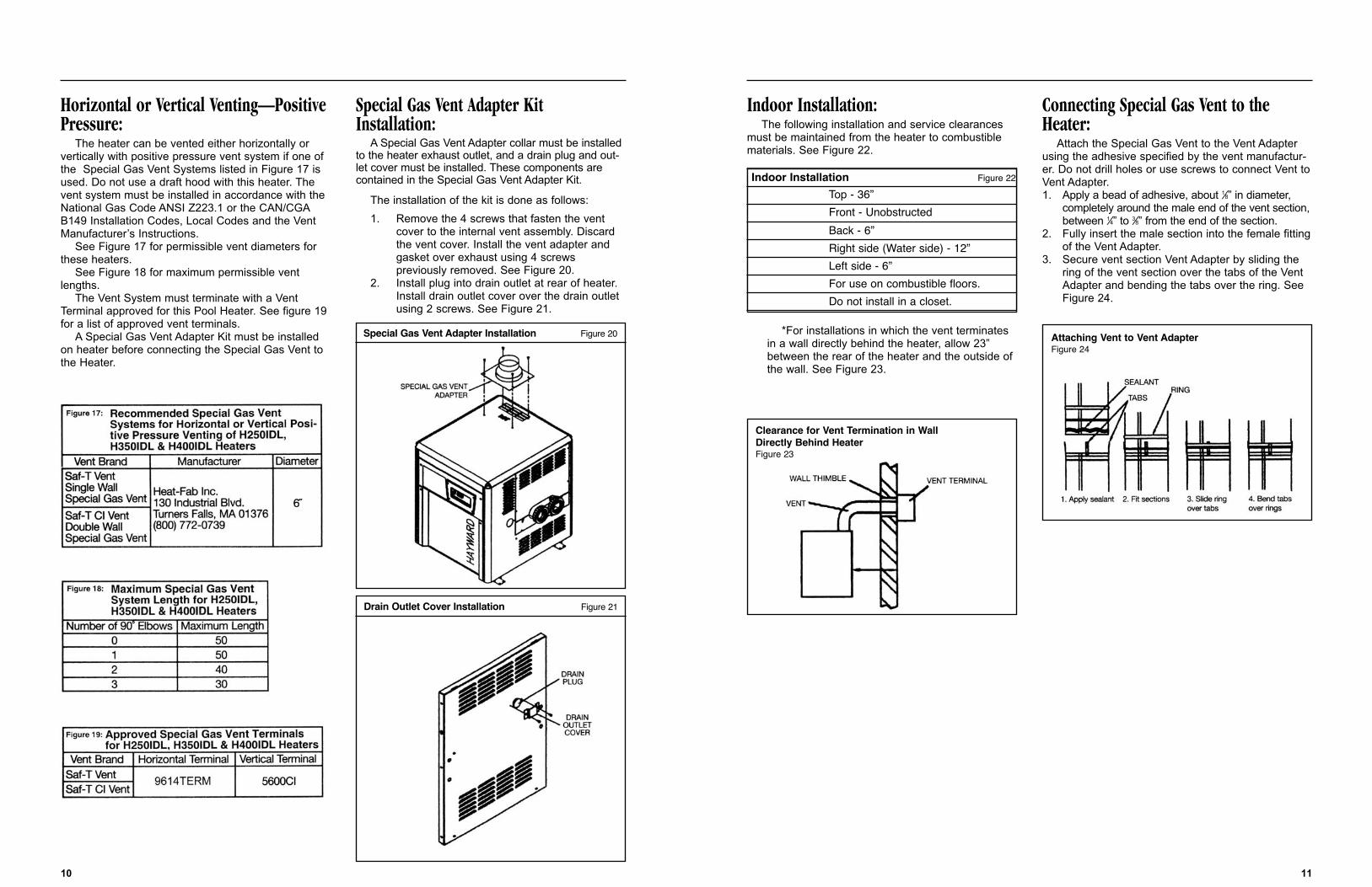
Indoor Installation:The following installation and service clearances
must be maintained from the heater to combustiblematerials. See Figure 22.
*For installations in which the vent terminatesin a wall directly behind the heater, allow 23”between the rear of the heater and the outside ofthe wall. See Figure 23.
Connecting Special Gas Vent to theHeater:
Attach the Special Gas Vent to the Vent Adapterusing the adhesive specified by the vent manufactur-er. Do not drill holes or use screws to connect Vent toVent Adapter.1. Apply a bead of adhesive, about 1⁄8” in diameter,
completely around the male end of the vent section,between 1⁄4” to 3⁄8” from the end of the section.
2. Fully insert the male section into the female fittingof the Vent Adapter.
3. Secure vent section Vent Adapter by sliding the ring of the vent section over the tabs of the Vent Adapter and bending the tabs over the ring. See Figure 24.
11
Horizontal or Vertical Venting—PositivePressure:
The heater can be vented either horizontally orvertically with positive pressure vent system if one ofthe Special Gas Vent Systems listed in Figure 17 isused. Do not use a draft hood with this heater. Thevent system must be installed in accordance with theNational Gas Code ANSI Z223.1 or the CAN/CGAB149 Installation Codes, Local Codes and the VentManufacturer’s Instructions.
See Figure 17 for permissible vent diameters forthese heaters.
See Figure 18 for maximum permissible ventlengths.
The Vent System must terminate with a VentTerminal approved for this Pool Heater. See figure 19for a list of approved vent terminals.
A Special Gas Vent Adapter Kit must be installedon heater before connecting the Special Gas Vent tothe Heater.
Special Gas Vent Adapter KitInstallation:
A Special Gas Vent Adapter collar must be installedto the heater exhaust outlet, and a drain plug and out-let cover must be installed. These components arecontained in the Special Gas Vent Adapter Kit.
The installation of the kit is done as follows:1. Remove the 4 screws that fasten the vent
cover to the internal vent assembly. Discard the vent cover. Install the vent adapter andgasket over exhaust using 4 screws previously removed. See Figure 20.
2. Install plug into drain outlet at rear of heater. Install drain outlet cover over the drain outlet using 2 screws. See Figure 21.
10
Special Gas Vent Adapter Installation Figure 20
Drain Outlet Cover Installation Figure 21
Clearance for Vent Termination in WallDirectly Behind HeaterFigure 23
Attaching Vent to Vent AdapterFigure 24
Indoor Installation Figure 22
Top - 36”Front - UnobstructedBack - 6”Right side (Water side) - 12”Left side - 6”For use on combustible floors.Do not install in a closet.
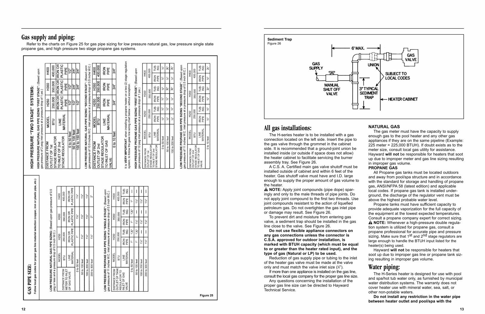
All gas installations:The H-series heater is to be installed with a gas
connection located on the left side. Insert the pipe tothe gas valve through the grommet in the cabinetside. It is recommended that a ground-joint union beinstalled inside (or outside if space does not allow)the heater cabinet to facilitate servicing the burnerassembly tray. See Figure 26.
A C.S. A. Certified main gas valve shutoff must beinstalled outside of cabinet and within 6 feet of theheater. Gas shutoff valve must have and I.D. largeenough to supply the proper amount of gas volume tothe heater.
NOTE: Apply joint compounds (pipe dope) spar-ingly and only to the male threads of pipe joints. Donot apply joint compound to the first two threads. Usejoint compounds resistant to the action of liquefiedpetroleum gas. Do not overtighten the gas inlet pipeor damage may result. See Figure 26.
To prevent dirt and moisture from entering gasvalve, a sediment trap should be installed in the gasline close to the valve. See Figure 26.
Do not use flexible appliance connectors onany gas connections unless the connector isC.S.A. approved for outdoor installation, ismarked with BTUH capacity (which must be equalto or greater than the heater rated input), and thetype of gas (Natural or LP) to be used.
Reduction of gas supply pipe or tubing to the inletof the heater gas valve must be made at the valveonly and must match the valve inlet size (3⁄4”).
If more than one appliance is installed on the gas line,consult the local gas company for the proper gas line size.
Any questions concerning the installation of theproper gas line size can be directed to HaywardTechnical Service.
NATURAL GASThe gas meter must have the capacity to supply
enough gas to the pool heater and any other gasappliances if they are on the same pipeline (Example:225 meter = 225,000 BTUH). If doubt exists as to themeter size, consult local gas utility for assistance.Hayward will not be responsible for heaters that sootup due to improper meter and gas line sizing resultingin improper gas volume.PROPANE GAS
All Propane gas tanks must be located outdoorsand away from pool/spa structure and in accordancewith the standard for storage and handling of propanegas, ANSI/NFPA 58 (latest edition) and applicablelocal codes. If propane gas tank is installed under-ground, the discharge of the regulator vent must beabove the highest probable water level.
Propane tanks must have sufficient capacity toprovide adequate vaporization for the full capacity ofthe equipment at the lowest expected temperatures.Consult a propane company expert for correct sizing.
NOTE: Whenever a high-pressure double regula-tion system is utilized for propane gas, consult apropane professional for accurate pipe and pressuresizing. Make sure that 1st and 2nd stage regulators arelarge enough to handle the BTUH input listed for theheater(s) being used.
Hayward will not be responsible for heaters thatsoot up due to improper gas line or propane tank siz-ing resulting in improper gas volume.
Water piping:The H-Series heater is designed for use with pool
and spa/hot tub water only, as furnished by municipalwater distribution systems. The warranty does notcover heater use with mineral water, sea, salt, orother non-potable waters.
Do not install any restriction in the water pipebetween heater outlet and pool/spa with the
13
Gas supply and piping:Refer to the charts on Figure 25 for gas pipe sizing for low pressure natural gas, low pressure single state
propane gas, and high pressure two stage propane gas systems.
12
Sediment TrapFigure 26
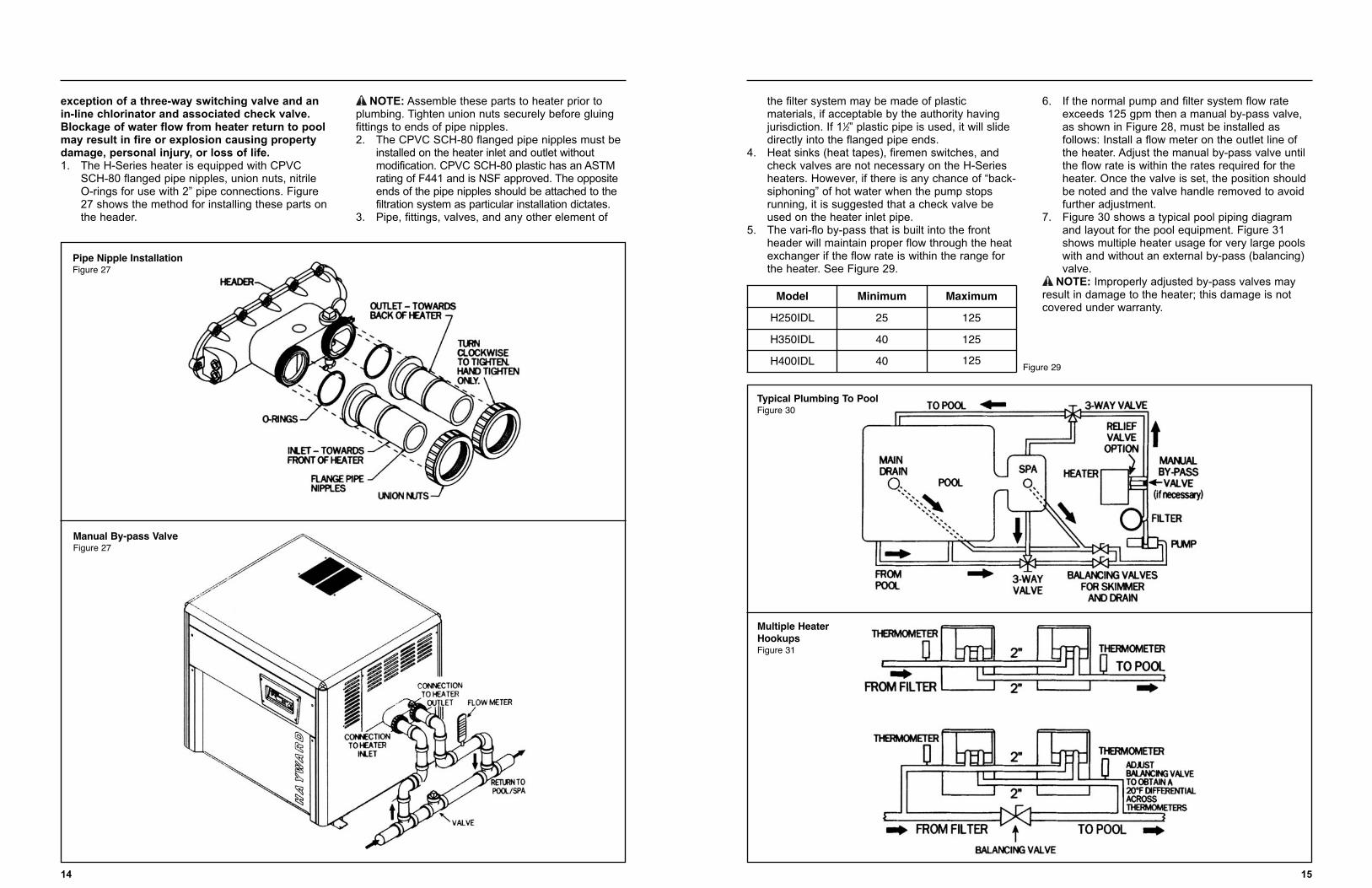
the filter system may be made of plastic materials, if acceptable by the authority having jurisdiction. If 11⁄2” plastic pipe is used, it will slide directly into the flanged pipe ends.
4. Heat sinks (heat tapes), firemen switches, and check valves are not necessary on the H-Series heaters. However, if there is any chance of “back-siphoning” of hot water when the pump stops running, it is suggested that a check valve be used on the heater inlet pipe.
5. The vari-flo by-pass that is built into the front header will maintain proper flow through the heat exchanger if the flow rate is within the range for the heater. See Figure 29.
6. If the normal pump and filter system flow rate exceeds 125 gpm then a manual by-pass valve, as shown in Figure 28, must be installed as follows: Install a flow meter on the outlet line of the heater. Adjust the manual by-pass valve until the flow rate is within the rates required for the heater. Once the valve is set, the position should be noted and the valve handle removed to avoid further adjustment.
7. Figure 30 shows a typical pool piping diagram and layout for the pool equipment. Figure 31 shows multiple heater usage for very large pools with and without an external by-pass (balancing) valve.
NOTE: Improperly adjusted by-pass valves mayresult in damage to the heater; this damage is notcovered under warranty.
15
exception of a three-way switching valve and anin-line chlorinator and associated check valve.Blockage of water flow from heater return to poolmay result in fire or explosion causing propertydamage, personal injury, or loss of life.1. The H-Series heater is equipped with CPVC
SCH-80 flanged pipe nipples, union nuts, nitrile O-rings for use with 2” pipe connections. Figure 27 shows the method for installing these parts on the header.
NOTE: Assemble these parts to heater prior toplumbing. Tighten union nuts securely before gluingfittings to ends of pipe nipples.2. The CPVC SCH-80 flanged pipe nipples must be
installed on the heater inlet and outlet without modification. CPVC SCH-80 plastic has an ASTM rating of F441 and is NSF approved. The opposite ends of the pipe nipples should be attached to the filtration system as particular installation dictates.
3. Pipe, fittings, valves, and any other element of
14
Pipe Nipple InstallationFigure 27
Manual By-pass ValveFigure 27
Typical Plumbing To PoolFigure 30
Figure 29
Multiple HeaterHookupsFigure 31
Model Minimum Maximum
H250IDL 25 125
H350IDL 40 125
H400IDL 40 125
Wiring Diagram Figure 35
Electrical connections:The heater is equipped with a Hot Surface Ignition
Control System that automatically lights the burners.An external power supply is required to power thecontrol system.
The heater comes factory-wired for use with a 240VAC, 60 Hz, field power supply. To convert the heaterto 120 VAC, 60 Hz, remove the 240 VAC VoltageSelector Plug from the receptacle on the Fuse Board.Locate the 120 VAC Voltage Selector Plug and installit into the receptacle.
All wiring connections to the heater must be madein accordance with the latest edition of the NationalElectrical Code ANSI/NFPA 70, unless local coderequirements specify otherwise. In Canada, follow CSAC22.1 – CANADIAN ELECTRICAL CODE, Part 1.
The heater must be electrically grounded andbonded in accordance with local codes, or in theabsence of local codes, with National Electrical Code,ANSI/NFPAA 70.
The H-Series heater must be installed with theelectrical connections, service entry/remote control,located on the left side of the heater.
Field wiring connections are to be made to theFuse Board behind the control access panel. Connectthe field supply wires to the terminal block on theFuse Board. Connect the ground wire to the lug adja-cent to the Fuse Board. Tighten terminal screws to 8in-lbs.
17
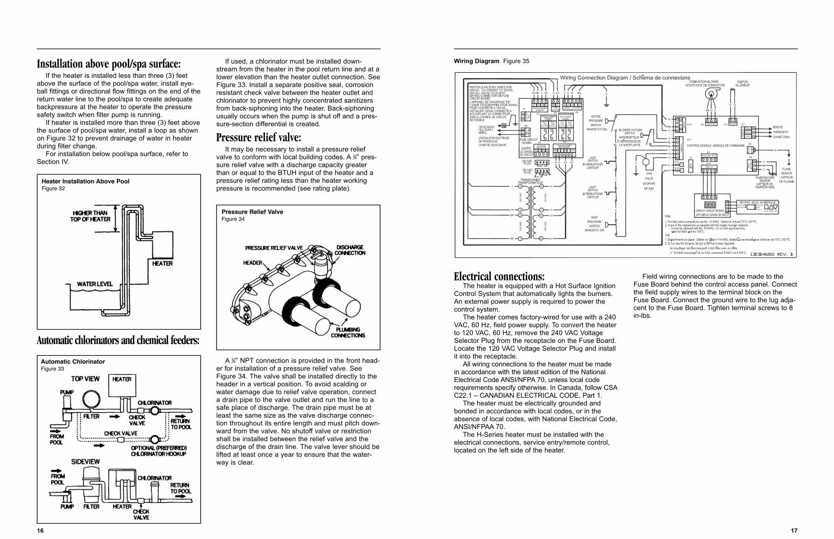
Installation above pool/spa surface:If the heater is installed less than three (3) feet
above the surface of the pool/spa water, install eye-ball fittings or directional flow fittings on the end of thereturn water line to the pool/spa to create adequatebackpressure at the heater to operate the pressuresafety switch when filter pump is running.
If heater is installed more than three (3) feet abovethe surface of pool/spa water, install a loop as shownon Figure 32 to prevent drainage of water in heaterduring filter change.
For installation below pool/spa surface, refer toSection IV.
Automatic chlorinators and chemical feeders:
If used, a chlorinator must be installed down-stream from the heater in the pool return line and at alower elevation than the heater outlet connection. SeeFigure 33. Install a separate positive seal, corrosionresistant check valve between the heater outlet andchlorinator to prevent highly concentrated sanitizersfrom back-siphoning into the heater. Back-siphoningusually occurs when the pump is shut off and a pres-sure-section differential is created.
Pressure relief valve:It may be necessary to install a pressure relief
valve to conform with local building codes. A 3⁄4” pres-sure relief valve with a discharge capacity greaterthan or equal to the BTUH input of the heater and apressure relief rating less than the heater workingpressure is recommended (see rating plate).
A 3⁄4” NPT connection is provided in the front head-er for installation of a pressure relief valve. SeeFigure 34. The valve shall be installed directly to theheader in a vertical position. To avoid scalding orwater damage due to relief valve operation, connecta drain pipe to the valve outlet and run the line to asafe place of discharge. The drain pipe must be atleast the same size as the valve discharge connec-tion throughout its entire length and must pitch down-ward from the valve. No shutoff valve or restrictionshall be installed between the relief valve and thedischarge of the drain line. The valve lever should belifted at least once a year to ensure that the water-way is clear.
16
Heater Installation Above PoolFigure 32
Automatic ChlorinatorFigure 33
Pressure Relief ValveFigure 34
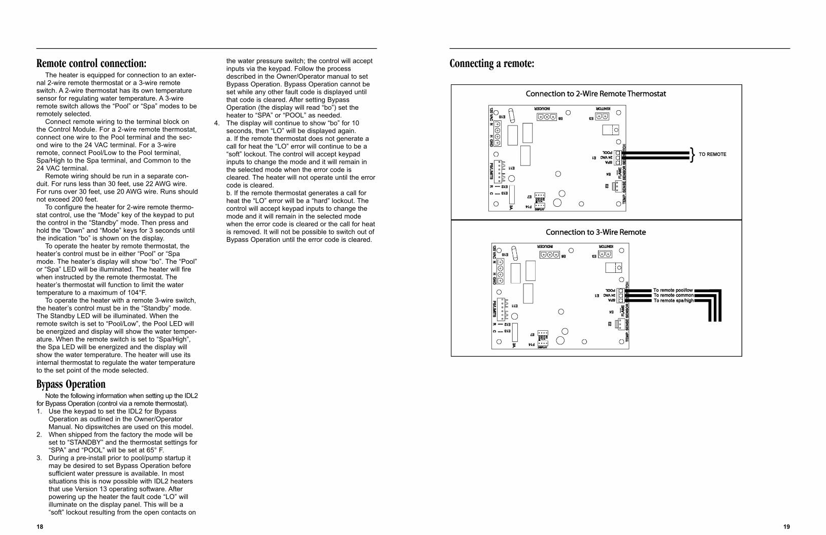
Connecting a remote:
19
Remote control connection:The heater is equipped for connection to an exter-
nal 2-wire remote thermostat or a 3-wire remoteswitch. A 2-wire thermostat has its own temperaturesensor for regulating water temperature. A 3-wireremote switch allows the “Pool” or “Spa” modes to beremotely selected.
Connect remote wiring to the terminal block onthe Control Module. For a 2-wire remote thermostat,connect one wire to the Pool terminal and the sec-ond wire to the 24 VAC terminal. For a 3-wireremote, connect Pool/Low to the Pool terminal,Spa/High to the Spa terminal, and Common to the24 VAC terminal.
Remote wiring should be run in a separate con-duit. For runs less than 30 feet, use 22 AWG wire.For runs over 30 feet, use 20 AWG wire. Runs shouldnot exceed 200 feet.
To configure the heater for 2-wire remote thermo-stat control, use the “Mode” key of the keypad to putthe control in the “Standby” mode. Then press andhold the “Down” and “Mode” keys for 3 seconds untilthe indication “bo” is shown on the display.
To operate the heater by remote thermostat, theheater’s control must be in either “Pool” or “Spamode. The heater’s display will show “bo”. The “Pool”or “Spa” LED will be illuminated. The heater will firewhen instructed by the remote thermostat. Theheater’s thermostat will function to limit the watertemperature to a maximum of 104°F.
To operate the heater with a remote 3-wire switch,the heater’s control must be in the “Standby” mode.The Standby LED will be illuminated. When theremote switch is set to “Pool/Low”, the Pool LED willbe energized and display will show the water temper-ature. When the remote switch is set to “Spa/High”,the Spa LED will be energized and the display willshow the water temperature. The heater will use itsinternal thermostat to regulate the water temperatureto the set point of the mode selected.
Bypass OperationNote the following information when setting up the IDL2
for Bypass Operation (control via a remote thermostat).1. Use the keypad to set the IDL2 for Bypass
Operation as outlined in the Owner/Operator Manual. No dipswitches are used on this model.
2. When shipped from the factory the mode will be set to “STANDBY” and the thermostat settings for“SPA” and “POOL” will be set at 65° F.
3. During a pre-install prior to pool/pump startup it may be desired to set Bypass Operation before sufficient water pressure is available. In most situations this is now possible with IDL2 heaters that use Version 13 operating software. After powering up the heater the fault code “LO” will illuminate on the display panel. This will be a “soft” lockout resulting from the open contacts on
the water pressure switch; the control will accept inputs via the keypad. Follow the process described in the Owner/Operator manual to set Bypass Operation. Bypass Operation cannot be set while any other fault code is displayed until that code is cleared. After setting Bypass Operation (the display will read “bo”) set the heater to “SPA” or “POOL” as needed.
4. The display will continue to show “bo” for 10 seconds, then “LO” will be displayed again.a. If the remote thermostat does not generate a call for heat the “LO” error will continue to be a “soft” lockout. The control will accept keypad inputs to change the mode and it will remain in the selected mode when the error code is cleared. The heater will not operate until the errorcode is cleared.b. If the remote thermostat generates a call for heat the “LO” error will be a “hard” lockout. The control will accept keypad inputs to change the mode and it will remain in the selected mode when the error code is cleared or the call for heatis removed. It will not be possible to switch out of Bypass Operation until the error code is cleared.
18
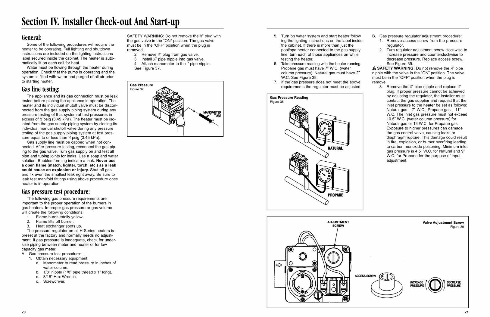
5. Turn on water system and start heater following the lighting instructions on the label insidethe cabinet. If there is more than just the pool/spa heater connected to the gas supply line, turn each of those appliances on while testing the heater.
6. Take pressure reading with the heater running. Propane gas must have 7” W.C. (water column pressure). Natural gas must have 2” W.C. See Figure 38.
7. If the gas pressure does not meet the above requirements the regulator must be adjusted.
B. Gas pressure regulator adjustment procedure:1. Remove access screw from the pressure
regulator.2. Turn regulator adjustment screw clockwise to
increase pressure and counterclockwise to decrease pressure. Replace access screw.See Figure 39.
SAFETY WARNING: Do not remove the 1⁄8” pipenipple with the valve in the “ON” position. The valvemust be in the “OFF” position when the plug isremove.
3. Remove the 1⁄8” pipe nipple and replace 1⁄8”plug. If proper pressure cannot be achieved by adjusting the regulator, the installer must contact the gas supplier and request that the inlet pressure to the heater be set as follows: Natural gas – 7” W.C., Propane gas – 11” W.C. The inlet gas pressure must not exceed 10.5” W.C. (water column pressure) for Natural gas or 13 W.C. for Propane gas. Exposure to higher pressures can damage the gas control valve, causing leaks or diaphragm rupture. This damage could result in fire, explosion, or burner overfiring leading to carbon monoxide poisoning. Minimum inletgas pressure is 4.5” W.C. for Natural and 9” W.C. for Propane for the purpose of input adjustment.
21
Section IV. Installer Check-out And Start-upGeneral:
Some of the following procedures will require theheater to be operating. Full lighting and shutdowninstructions are included on the lighting instructionslabel secured inside the cabinet. The heater is auto-matically lit on each call for heat.
Water must be flowing through the heater duringoperation. Check that the pump is operating and thesystem is filled with water and purged of all air priorto starting heater.
Gas line testing:The appliance and its gas connection must be leak
tested before placing the appliance in operation. Theheater and its individual shutoff valve must be discon-nected from the gas supply piping system during anypressure testing of that system at test pressures inexcess of 1⁄2 psig (3.45 kPa). The heater must be iso-lated from the gas supply piping system by closing itsindividual manual shutoff valve during any pressuretesting of the gas supply piping system at test pres-sure equal to or less than 1⁄2 psig (3.45 kPa).
Gas supply line must be capped when not con-nected. After pressure testing, reconnect the gas pip-ing to the gas valve. Turn gas supply on and test allpipe and tubing joints for leaks. Use a soap and watersolution. Bubbles forming indicate a leak. Never usea open flame (match, lighter, torch, etc.) as a leakcould cause an explosion or injury. Shut off gasand fix even the smallest leak right away. Be sure toleak test manifold fittings using above procedure onceheater is in operation.
Gas pressure test procedure:The following gas pressure requirements are
important to the proper operation of the burners ingas heaters. Improper gas pressure or gas volumewill create the following conditions:
1. Flame burns totally yellow.2. Flame lifts off burner.3. Heat exchanger soots up.The pressure regulator on all H-Series heaters is
preset at the factory and normally needs no adjust-ment. If gas pressure is inadequate, check for under-size piping between meter and heater or for lowcapacity gas meter.A. Gas pressure test procedure:
1. Obtain necessary equipment:a. Manometer to read pressure in inches of
water column.b. 1/8” nipple (1/8” pipe thread x 1” long).c. 3/16” Hex Wrench.d. Screwdriver.
SAFETY WARNING: Do not remove the 1⁄8” plug withthe gas valve in the “ON” position. The gas valvemust be in the “OFF” position when the plug isremoved.
2. Remove 1⁄8” plug from gas valve.3. Install 1⁄8” pipe nipple into gas valve.4. Attach manometer to the ” pipe nipple. See Figure 37.
20
Gas PressureFigure 37
Gas Pressure ReadingFigure 38
Valve Adjustment ScrewFigure 39
Section V. Consumer Operation & Maintenance Procedures
General:Water must be flowing through heater during oper-
ation. Check that the pump is operating and the sys-tem is filled with water and purged of all air prior tostarting heater. In a new pool it is recommended thatthe filter be operated long enough to completely cleanand clear the pool water and filter system.
Balance the pool/spa water chemistry and cleanthe filter. Then follow the instructions below.
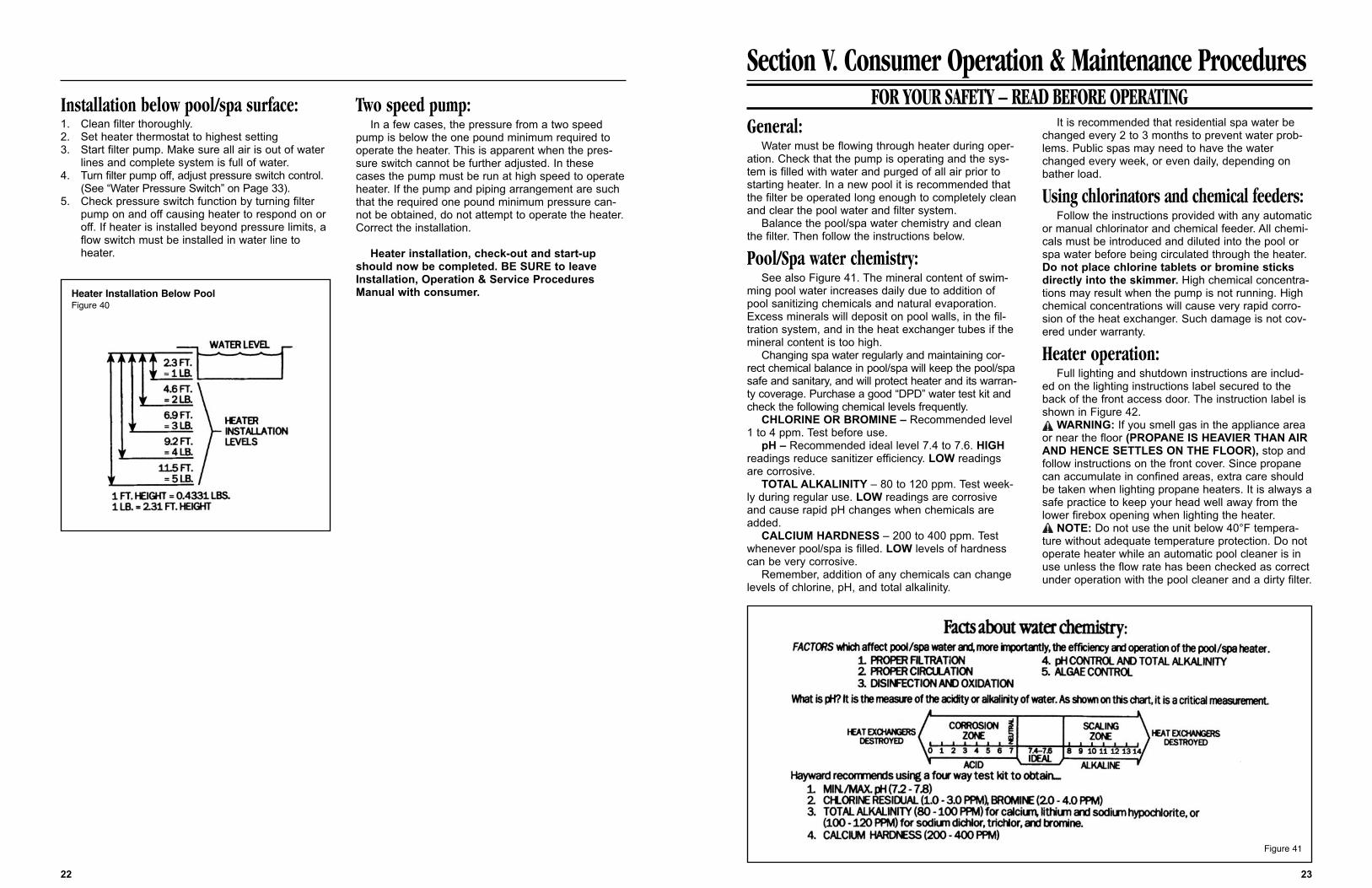
Pool/Spa water chemistry:See also Figure 41. The mineral content of swim-
ming pool water increases daily due to addition ofpool sanitizing chemicals and natural evaporation.Excess minerals will deposit on pool walls, in the fil-tration system, and in the heat exchanger tubes if themineral content is too high.
Changing spa water regularly and maintaining cor-rect chemical balance in pool/spa will keep the pool/spasafe and sanitary, and will protect heater and its warran-ty coverage. Purchase a good “DPD” water test kit andcheck the following chemical levels frequently.
CHLORINE OR BROMINE – Recommended level1 to 4 ppm. Test before use.
pH – Recommended ideal level 7.4 to 7.6. HIGHreadings reduce sanitizer efficiency. LOW readingsare corrosive.
TOTAL ALKALINITY – 80 to 120 ppm. Test week-ly during regular use. LOW readings are corrosiveand cause rapid pH changes when chemicals areadded.
CALCIUM HARDNESS – 200 to 400 ppm. Testwhenever pool/spa is filled. LOW levels of hardnesscan be very corrosive.
Remember, addition of any chemicals can changelevels of chlorine, pH, and total alkalinity.
It is recommended that residential spa water bechanged every 2 to 3 months to prevent water prob-lems. Public spas may need to have the waterchanged every week, or even daily, depending onbather load.
Using chlorinators and chemical feeders:Follow the instructions provided with any automatic
or manual chlorinator and chemical feeder. All chemi-cals must be introduced and diluted into the pool orspa water before being circulated through the heater.Do not place chlorine tablets or bromine sticksdirectly into the skimmer. High chemical concentra-tions may result when the pump is not running. Highchemical concentrations will cause very rapid corro-sion of the heat exchanger. Such damage is not cov-ered under warranty.
Heater operation:Full lighting and shutdown instructions are includ-
ed on the lighting instructions label secured to theback of the front access door. The instruction label isshown in Figure 42.
WARNING: If you smell gas in the appliance areaor near the floor (PROPANE IS HEAVIER THAN AIRAND HENCE SETTLES ON THE FLOOR), stop andfollow instructions on the front cover. Since propanecan accumulate in confined areas, extra care shouldbe taken when lighting propane heaters. It is always asafe practice to keep your head well away from thelower firebox opening when lighting the heater.
NOTE: Do not use the unit below 40°F tempera-ture without adequate temperature protection. Do notoperate heater while an automatic pool cleaner is inuse unless the flow rate has been checked as correctunder operation with the pool cleaner and a dirty filter.
23
Installation below pool/spa surface:1. Clean filter thoroughly.2. Set heater thermostat to highest setting3. Start filter pump. Make sure all air is out of water
lines and complete system is full of water.4. Turn filter pump off, adjust pressure switch control.
(See “Water Pressure Switch” on Page 33).5. Check pressure switch function by turning filter
pump on and off causing heater to respond on or off. If heater is installed beyond pressure limits, a flow switch must be installed in water line to heater.
Two speed pump:In a few cases, the pressure from a two speed
pump is below the one pound minimum required tooperate the heater. This is apparent when the pres-sure switch cannot be further adjusted. In thesecases the pump must be run at high speed to operateheater. If the pump and piping arrangement are suchthat the required one pound minimum pressure can-not be obtained, do not attempt to operate the heater.Correct the installation.
Heater installation, check-out and start-upshould now be completed. BE SURE to leaveInstallation, Operation & Service ProceduresManual with consumer.
22
FOR YOUR SAFETY – READ BEFORE OPERATING
Heater Installation Below PoolFigure 40
Figure 41
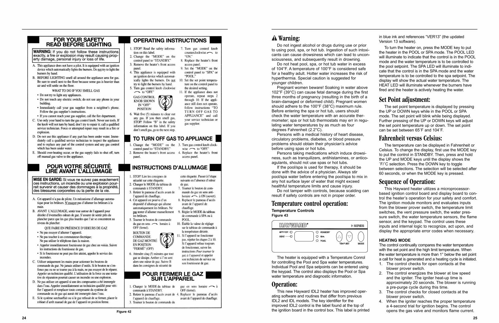
Warning:Do not ingest alcohol or drugs during use or prior
to using pool, spa, or hot tub. Ingestion of such intoxi-cants can cause drowsiness which can lead to uncon-sciousness, and subsequently result in drowning.
Do not heat pool, spa, or hot tub water in excessof 104°F. A temperature of 100°F is considered safefor a healthy adult. Hotter water increases the risk ofhyperthermia. Special caution is suggested foryounger children.
Pregnant women beware! Soaking in water above102°F (39°C) can cause fetal damage during the firstthree months of pregnancy (resulting in the birth of abrain-damaged or deformed child). Pregnant womenshould adhere to the 100°F (38°C) maximum rule.Before entering the spa or hot tub, users shouldcheck the water temperature with an accurate ther-mometer; spa or hot tub thermostats may err in regu-lating water temperatures by as much as fourdegrees Fahrenheit (2.2°C).
Persons with a medical history of heart disease,circulatory problems, diabetes, or blood pressureproblems should obtain their physician’s advicebefore using spas or hot tubs.
Persons taking medications which induce drowsi-ness, such as tranquilizers, antihistamines, or antico-agulants, should not use spas or hot tubs.
If the pool/spa is used for therapy, it should bedone with the advice of a physician. Always stirpool/spa water before entering the pool/spa to mix inany hot surface layer of water that might exceedhealthful temperature limits and cause injury.
Do not tamper with controls, because scalding canresult if safety controls are not in proper order.
Temperature control operation:Temperature ControlsFigure 43
The heater is equipped with a Temperature Conrolfor controlling the Pool and Spa water temperatures.Individual Pool and Spa setpoints can be entered usingthe keypad. The control also displays the Pool or Spawater temperature and diagnostic information.
Operation:This new Hayward IDL2 heater has improved oper-
ating software and routines that differ from previousIDL2 and IDL models. The key identifier for theimproved IDL2 control is the label found at the top ofthe ignition board in the control box. This label is printed
in blue ink and references “VER13” (the updatedVersion 13 software).
To turn the heater on, press the MODE key to putthe heater in the POOL or SPA mode. The POOL LEDwill illuminate to indicate that the control is in the POOLmode and the water temperature is to be controlled tothe pool setpoint. The SPA LED will illuminate to indi-cate that the control is in the SPA mode and the watertemperature is to be controlled to the spa setpoint. Thedisplay will show the actual water temperature. TheHEAT LED will illuminate whenever the burners havefired and the heater is actively heating the water.
Set Point adjustment:The set point temperature is displayed by pressing
the UP or DOWN keys while in the POOL or SPAmode. The set point will blink while being displayed.Further pressing of the UP or DOWN keys will adjustthe set point temperature up or down. The set pointcan be set between 65˚F and 104˚F.
Fahrenheit versus Celsius:The temperature can be displayed in Fahrenheit or
Celsius. To change the display, first use the MODE keyto put the control in STANDBY. Then, press and holdthe UP and MODE keys until the display shows the˚F/˚C selection. Press the DOWN key to togglebetween selections. The selection will be selected after60 seconds, or when the MODE key is pressed.
Sequence of Operation:This Hayward heater utilizes a microprocessor-
based ignition control board and display board to con-trol the heater’s operation for your safety and comfort.The ignition module monitors and evaluates inputsfrom the blower prover switch, the temperature limitswitches, the vent pressure switch, the water pres-sure switch, the water temperature sensors, the flamesensor, and the keypad. The control uses theseinputs and internal logic to recognize, act upon, anddisplay the appropriate error codes when necessary.
HEATING MODEThe control continually compares the water temperaturewith the set point and the high limit temperature. Whenthe water temperature is more than 1° below the set pointa call for heat is generated and a heating cycle is initiated.1. The control checks for open contacts at the
blower prover switch.2. The control energizes the blower at low speed
and the igniter. The igniter heat-up time is approximately 20 seconds. The blower is running a pre-purge cycle during this time.
3. The control checks for closed contacts at the blower prover switch.
4. When the igniter reaches the proper temperature a 4-second trial for ignition begins. The control opens the gas valve and monitors flame current.
2524
Figure 42
1. Periodically check the venting system on outdoor heaters. The heater’s venting areas must never be obstructed in any way and minimum clearances must be observed to prevent restriction of combus-tion and ventilation air. Remember shrubs grow andin time may obstruct a heater’s venting areas.
2. Check the venting of indoor heaters for loosenessand possible leaks. Keep all openings for com-bustion and ventilation air clear and unobstructed.
3. Keep the entire pool heater area clean and free of all debris, combustible materials, gasoline and other flammable vapors and liquids. Remove any leaves or paper from around the heater.
4. Do not store chlorine, other pool chemicals, or other corrosives in the vicinity of the heater.
5. If heater is operating on Propane gas, Propane tank must not fall below 30% full or damage to the heater may occur. Hayward will not be responsible for heaters that soot up due to improper gas level in tank resulting in inadequate gas volume.
6. If another appliance is added to the gas line at a later date, consult local gas company to be sure the gas line will have the capacity to supply both units at full capacity at the same time.
7. Do not use the heater if any part has been under water. Contact a qualified service technician to inspect the entire heater and replace any part of the control system or gas valve that was under water. If heater has been totally submerged in water, replace the entire heater.
8. An inspection program is a good preventative maintenance measure. Keep this manual in a safe place for future reference and also for a service technician when inspecting or servicing heater. Additional inspection procedures to be performed by a qualified service technician are covered in Section VI of this manual.
Winterization:In moderate climate, the heater can continue to
operate during short-term cold spells. Do not use theheater to maintain the water temperature just abovefreezing or for freeze protection. Care must be takento avoid freeze-up in the heater. When it is used dur-ing freezing weather, the pump must run continuous-ly. The heater is not warranted against freeze-ups.
In regions where freezing temperatures are encoun-tered, all water must be drained from the heater whenout of service, to prevent damage to the heater andpiping. Draining heat exchanger is recommended aspart of the season’s shut-down procedures.
A HEATER DAMAGED BY FREEZING IS NOT COV-ERED UNDER THE MANUFACTURER’S WARRANTY.
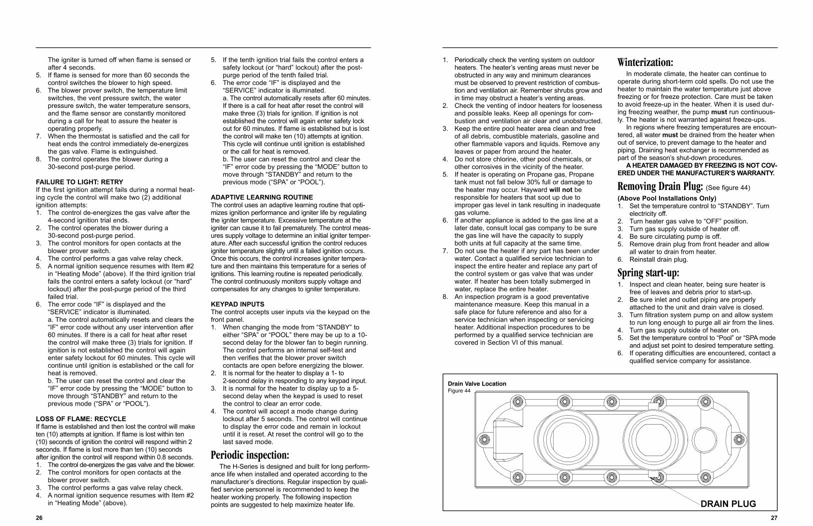
Removing Drain Plug: (See figure 44)(Above Pool Installations Only)1. Set the temperature control to “STANDBY”. Turn
electricity off.2. Turn heater gas valve to “OFF” position.3. Turn gas supply outside of heater off.4. Be sure circulating pump is off.5. Remove drain plug from front header and allow
all water to drain from heater.6. Reinstall drain plug.
Spring start-up:1. Inspect and clean heater, being sure heater is
free of leaves and debris prior to start-up.2. Be sure inlet and outlet piping are properly
attached to the unit and drain valve is closed.3. Turn filtration system pump on and allow system
to run long enough to purge all air from the lines.4. Turn gas supply outside of heater on.5. Set the temperature control to “Pool” or “SPA mode
and adjust set point to desired temperature setting.6. If operating difficulties are encountered, contact a
qualified service company for assistance.
27
The igniter is turned off when flame is sensed or after 4 seconds.
5. If flame is sensed for more than 60 seconds the control switches the blower to high speed.
6. The blower prover switch, the temperature limit switches, the vent pressure switch, the water pressure switch, the water temperature sensors, and the flame sensor are constantly monitored during a call for heat to assure the heater is operating properly.
7. When the thermostat is satisfied and the call for heat ends the control immediately de-energizes the gas valve. Flame is extinguished.
8. The control operates the blower during a 30-second post-purge period.
FAILURE TO LIGHT: RETRYIf the first ignition attempt fails during a normal heat-ing cycle the control will make two (2) additionalignition attempts:1. The control de-energizes the gas valve after the
4-second ignition trial ends.2. The control operates the blower during a
30-second post-purge period.3. The control monitors for open contacts at the
blower prover switch.4. The control performs a gas valve relay check.5. A normal ignition sequence resumes with Item #2
in “Heating Mode” (above). If the third ignition trialfails the control enters a safety lockout (or “hard” lockout) after the post-purge period of the third failed trial.
6. The error code “IF” is displayed and the “SERVICE” indicator is illuminated.a. The control automatically resets and clears the “IF” error code without any user intervention after 60 minutes. If there is a call for heat after reset the control will make three (3) trials for ignition. If ignition is not established the control will again enter safety lockout for 60 minutes. This cycle willcontinue until ignition is established or the call for heat is removed.b. The user can reset the control and clear the “IF” error code by pressing the “MODE” button to move through “STANDBY” and return to the previous mode (“SPA” or “POOL”).
LOSS OF FLAME: RECYCLEIf flame is established and then lost the control will maketen (10) attempts at ignition. If flame is lost within ten(10) seconds of ignition the control will respond within 2seconds. If flame is lost more than ten (10) secondsafter ignition the control will respond within 0.8 seconds.1. The control de-energizes the gas valve and the blower.2. The control monitors for open contacts at the
blower prover switch.3. The control performs a gas valve relay check.4. A normal ignition sequence resumes with Item #2
in “Heating Mode” (above).
5. If the tenth ignition trial fails the control enters a safety lockout (or “hard” lockout) after the post-purge period of the tenth failed trial.
6. The error code “IF” is displayed and the “SERVICE” indicator is illuminated.a. The control automatically resets after 60 minutes.If there is a call for heat after reset the control will make three (3) trials for ignition. If ignition is not established the control will again enter safety lockout for 60 minutes. If flame is established but is lostthe control will make ten (10) attempts at ignition. This cycle will continue until ignition is established or the call for heat is removed.b. The user can reset the control and clear the “IF” error code by pressing the “MODE” button to move through “STANDBY” and return to the previous mode (“SPA” or “POOL”).
ADAPTIVE LEARNING ROUTINEThe control uses an adaptive learning routine that opti-mizes ignition performance and igniter life by regulatingthe igniter temperature. Excessive temperature at theigniter can cause it to fail prematurely. The control meas-ures supply voltage to determine an initial igniter temper-ature. After each successful ignition the control reducesigniter temperature slightly until a failed ignition occurs.Once this occurs, the control increases igniter tempera-ture and then maintains this temperature for a series ofignitions. This learning routine is repeated periodically.The control continuously monitors supply voltage andcompensates for any changes to igniter temperature.
KEYPAD INPUTSThe control accepts user inputs via the keypad on thefront panel.1. When changing the mode from “STANDBY” to
either “SPA” or “POOL” there may be up to a 10-second delay for the blower fan to begin running. The control performs an internal self-test and then verifies that the blower prover switch contacts are open before energizing the blower.
2. It is normal for the heater to display a 1- to 2-second delay in responding to any keypad input.
3. It is normal for the heater to display up to a 5-second delay when the keypad is used to reset the control to clear an error code.
4. The control will accept a mode change during lockout after 5 seconds. The control will continue to display the error code and remain in lockout until it is reset. At reset the control will go to the last saved mode.
Periodic inspection:The H-Series is designed and built for long perform-
ance life when installed and operated according to themanufacturer’s directions. Regular inspection by quali-fied service personnel is recommended to keep theheater working properly. The following inspectionpoints are suggested to help maximize heater life.
26
DRAIN PLUG
Drain Valve LocationFigure 44
WARNING: It is not recommended that a wirebrush be used to remove soot from the heat exchang-er. This may cause a spark and ignite the gasestrapped within the soot.
Using a soft tipped brush such as a “paint brush”apply a degreaser to the entire heat exchanger sur-face top and bottom. Note: If an old style heatexchanger, remove “V” baffles prior to performingany cleaning. Allow the heat exchanger to sit for aperiod of time to allow the degreaser to loosen thesoot. Wash the heat exchanger using a garden hoseensuring both top and bottom surfaces are thoroughlycleaned. Follow the above procedure steps in reverseto re-install heat exchanger. Although the heatexchanger should be cleaned of soot and reinstalledin the heater, the fact that sooting occurred should beinvestigated, as it may be indicative of other prob-lems such as:• Insufficient air supply• Inadequate venting• High or low gas pressure• Blockage of burner tubes or orifices• Improper heater location installation• Incorrect gas supply pipe size• Excessive water flow through heat exchanger• LP tank below 30% full.
Combustion Chamber:The combustion chamber is a “one piece” box. If
damaged, the entire chamber must be replaced.
Heat exchanger removal:1. Turn pump, main gas valve and heater power off.2. Drain heat exchanger.3. Remove four screws from vent in top of heater
and remove top.4. Remove access covers from both sides of heater.5. Remove air deflector shield from around blower.6. Unplug blower wire connector.7. Disconnect pressure tap tubes from
blower/vent assembly.8. Remove flue collector assembly.9. Disconnect water pressure switch tube from
header.10. Disconnect high limit wires from header.11. Lift heat exchanger assembly straight up off
combustion chamber.12. Installation is the reverse of removal.
29
Section VI. Qualified Technician - Maintenance/ServicingGeneral:
IMPORTANT: Only qualified service technicians,having appropriate test equipment, should be allowedto service the heater. Bear in mind that all of the com-ponents that comprise the system have an effect onthe heater operation. Before proceeding with heaterrelated troubleshooting tips covered in Section VII, becertain that the pump is operating correctly, the filtersand strainers are not blocked, the valves in the pipingare properly positioned, and the time clocks are prop-erly set.
WARNING: Do not attempt to repair any compo-nents of heater. Do not modify heater in any manner.To do so may result in a malfunction which couldresult in death, personal injury, or property damage.Check with consumer to see if any part of heater hasbeen under water. Replace any part of the controlsystem and any gas control which has been underwater. Never use or attempt to use parts that havebeen previously used.
Maintenance:The following inspection procedures are recom-
mended to be performed as part of annual heatermaintenance and to assure safe operation.
1. External heat exchanger.2. Internal heat exchanger.3. Main burner flame patterns.4. Main burner orifices.5. Operating controls.
Inspection procedures are covered below. Some ofthe procedures will require disconnecting and remov-ing wires in the control department. See ControlAccess below.
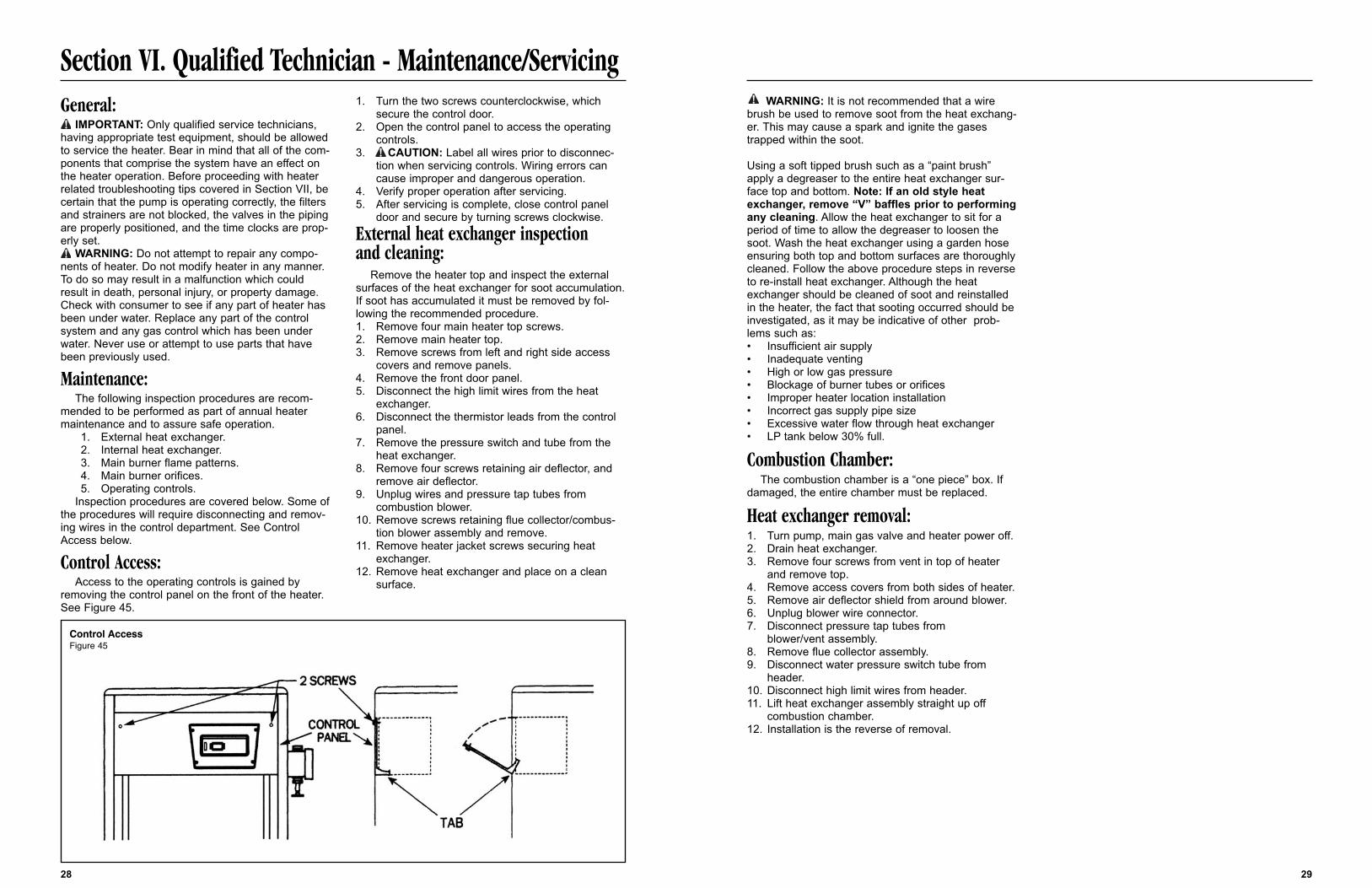
Control Access:Access to the operating controls is gained by
removing the control panel on the front of the heater.See Figure 45.
1. Turn the two screws counterclockwise, which secure the control door.
2. Open the control panel to access the operating controls.
3. CAUTION: Label all wires prior to disconnec-tion when servicing controls. Wiring errors can cause improper and dangerous operation.
4. Verify proper operation after servicing.5. After servicing is complete, close control panel
door and secure by turning screws clockwise.
External heat exchanger inspection and cleaning:
Remove the heater top and inspect the externalsurfaces of the heat exchanger for soot accumulation.If soot has accumulated it must be removed by fol-lowing the recommended procedure.1. Remove four main heater top screws.2. Remove main heater top.3. Remove screws from left and right side access
covers and remove panels.4. Remove the front door panel.5. Disconnect the high limit wires from the heat
exchanger.6. Disconnect the thermistor leads from the control
panel.7. Remove the pressure switch and tube from the
heat exchanger.8. Remove four screws retaining air deflector, and
remove air deflector.9. Unplug wires and pressure tap tubes from
combustion blower.10. Remove screws retaining flue collector/combus-
tion blower assembly and remove.11. Remove heater jacket screws securing heat
exchanger.12. Remove heat exchanger and place on a clean
surface.
28
Control AccessFigure 45
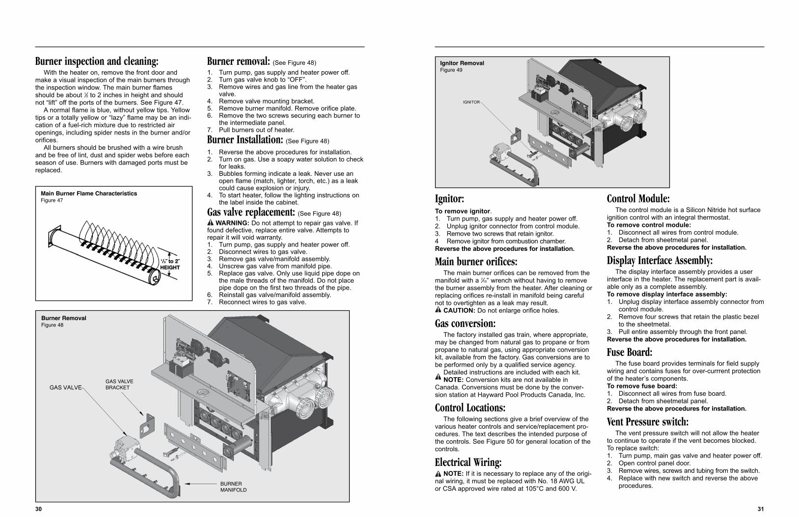
Ignitor:To remove ignitor.1. Turn pump, gas supply and heater power off.2. Unplug ignitor connector from control module.3. Remove two screws that retain ignitor.4 Remove ignitor from combustion chamber.Reverse the above procedures for installation.
Main burner orifices:The main burner orifices can be removed from the
manifold with a 7⁄16” wrench without having to removethe burner assembly from the heater. After cleaning orreplacing orifices re-install in manifold being carefulnot to overtighten as a leak may result.
CAUTION: Do not enlarge orifice holes.
Gas conversion:The factory installed gas train, where appropriate,
may be changed from natural gas to propane or frompropane to natural gas, using appropriate conversionkit, available from the factory. Gas conversions are tobe performed only by a qualified service agency.
Detailed instructions are included with each kit.NOTE: Conversion kits are not available in
Canada. Conversions must be done by the conver-sion station at Hayward Pool Products Canada, Inc.
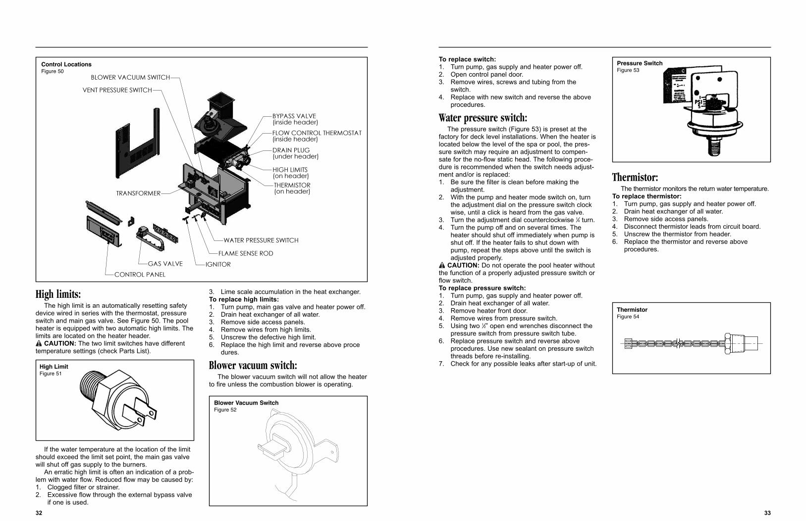
Control Locations:The following sections give a brief overview of the
various heater controls and service/replacement pro-cedures. The text describes the intended purpose ofthe controls. See Figure 50 for general location of thecontrols.
Electrical Wiring:NOTE: If it is necessary to replace any of the origi-
nal wiring, it must be replaced with No. 18 AWG ULor CSA approved wire rated at 105°C and 600 V.
Control Module:The control module is a Silicon Nitride hot surface
ignition control with an integral thermostat.To remove control module:1. Disconnect all wires from control module.2. Detach from sheetmetal panel.Reverse the above procedures for installation.
Display Interface Assembly:The display interface assembly provides a user
interface in the heater. The replacement part is avail-able only as a complete assembly.To remove display interface assembly:1. Unplug display interface assembly connector from
control module.2. Remove four screws that retain the plastic bezel
to the sheetmetal.3. Pull entire assembly through the front panel.Reverse the above procedures for installation.
Fuse Board:The fuse board provides terminals for field supply
wiring and contains fuses for over-currrent protectionof the heater’s components.To remove fuse board:1. Disconnect all wires from fuse board.2. Detach from sheetmetal panel.Reverse the above procedures for installation.
Vent Pressure switch:The vent pressure switch will not allow the heater
to continue to operate if the vent becomes blocked.To replace switch:1. Turn pump, main gas valve and heater power off.2. Open control panel door.3. Remove wires, screws and tubing from the switch.4. Replace with new switch and reverse the above
procedures.
31
Burner inspection and cleaning:With the heater on, remove the front door and
make a visual inspection of the main burners throughthe inspection window. The main burner flamesshould be about 1⁄2 to 2 inches in height and shouldnot “lift” off the ports of the burners. See Figure 47.
A normal flame is blue, without yellow tips. Yellowtips or a totally yellow or “lazy” flame may be an indi-cation of a fuel-rich mixture due to restricted airopenings, including spider nests in the burner and/ororifices.
All burners should be brushed with a wire brushand be free of lint, dust and spider webs before eachseason of use. Burners with damaged ports must bereplaced.
Burner removal: (See Figure 48)1. Turn pump, gas supply and heater power off.2. Turn gas valve knob to “OFF”.3. Remove wires and gas line from the heater gas
valve.4. Remove valve mounting bracket.5. Remove burner manifold. Remove orifice plate.6. Remove the two screws securing each burner to
the intermediate panel.7. Pull burners out of heater.
Burner Installation: (See Figure 48)
1. Reverse the above procedures for installation.2. Turn on gas. Use a soapy water solution to check
for leaks.3. Bubbles forming indicate a leak. Never use an
open flame (match, lighter, torch, etc.) as a leak could cause explosion or injury.
4. To start heater, follow the lighting instructions on the label inside the cabinet.
Gas valve replacement: (See Figure 48)WARNING: Do not attempt to repair gas valve. If
found defective, replace entire valve. Attempts torepair it will void warranty.1. Turn pump, gas supply and heater power off.2. Disconnect wires to gas valve.3. Remove gas valve/manifold assembly.4. Unscrew gas valve from manifold pipe.5. Replace gas valve. Only use liquid pipe dope on
the male threads of the manifold. Do not place pipe dope on the first two threads of the pipe.
6. Reinstall gas valve/manifold assembly.7. Reconnect wires to gas valve.
30
(9/$96$*
Main Burner Flame CharacteristicsFigure 47
Burner RemovalFigure 48
IGNITOR
Ignitor RemovalFigure 49
To replace switch:1. Turn pump, gas supply and heater power off.2. Open control panel door.3. Remove wires, screws and tubing from the
switch.4. Replace with new switch and reverse the above
procedures.
Water pressure switch:The pressure switch (Figure 53) is preset at the
factory for deck level installations. When the heater islocated below the level of the spa or pool, the pres-sure switch may require an adjustment to compen-sate for the no-flow static head. The following proce-dure is recommended when the switch needs adjust-ment and/or is replaced:1. Be sure the filter is clean before making the
adjustment.2. With the pump and heater mode switch on, turn
the adjustment dial on the pressure switch clockwise, until a click is heard from the gas valve.
3. Turn the adjustment dial counterclockwise 1⁄4 turn.4. Turn the pump off and on several times. The
heater should shut off immediately when pump is shut off. If the heater fails to shut down with pump, repeat the steps above until the switch is adjusted properly.
CAUTION: Do not operate the pool heater withoutthe function of a properly adjusted pressure switch orflow switch.To replace pressure switch: 1. Turn pump, gas supply and heater power off.2. Drain heat exchanger of all water.3. Remove heater front door.4. Remove wires from pressure switch.5. Using two 1⁄2” open end wrenches disconnect the
pressure switch from pressure switch tube.6. Replace pressure switch and reverse above
procedures. Use new sealant on pressure switch threads before re-installing.
7. Check for any possible leaks after start-up of unit.
Thermistor:The thermistor monitors the return water temperature.
To replace thermistor:1. Turn pump, gas supply and heater power off.2. Drain heat exchanger of all water.3. Remove side access panels.4. Disconnect thermistor leads from circuit board.5. Unscrew the thermistor from header.6. Replace the thermistor and reverse above
procedures.
33
High limits:The high limit is an automatically resetting safety
device wired in series with the thermostat, pressureswitch and main gas valve. See Figure 50. The poolheater is equipped with two automatic high limits. Thelimits are located on the heater header.
CAUTION: The two limit switches have differenttemperature settings (check Parts List).
If the water temperature at the location of the limitshould exceed the limit set point, the main gas valvewill shut off gas supply to the burners.
An erratic high limit is often an indication of a prob-lem with water flow. Reduced flow may be caused by:1. Clogged filter or strainer.2. Excessive flow through the external bypass valve
if one is used.
3. Lime scale accumulation in the heat exchanger.To replace high limits:1. Turn pump, main gas valve and heater power off.2. Drain heat exchanger of all water.3. Remove side access panels.4. Remove wires from high limits.5. Unscrew the defective high limit.6. Replace the high limit and reverse above proce
dures.
Blower vacuum switch:The blower vacuum switch will not allow the heater
to fire unless the combustion blower is operating.
32
IGNITOR
FLAME SENSE ROD
WATER PRESSURE SWITCH
CONTROL PANEL
GAS VALVE
TRANSFORMER
VENT PRESSURE SWITCH
BLOWER VACUUM SWITCH
BYPASS VALVE(inside header)
FLOW CONTROL THERMOSTAT(inside header)
DRAIN PLUG(under header)
HIGH LIMITS(on header)THERMISTOR(on header)
Control LocationsFigure 50
High LimitFigure 51
Blower Vacuum SwitchFigure 52
Pressure SwitchFigure 53
ThermistorFigure 54
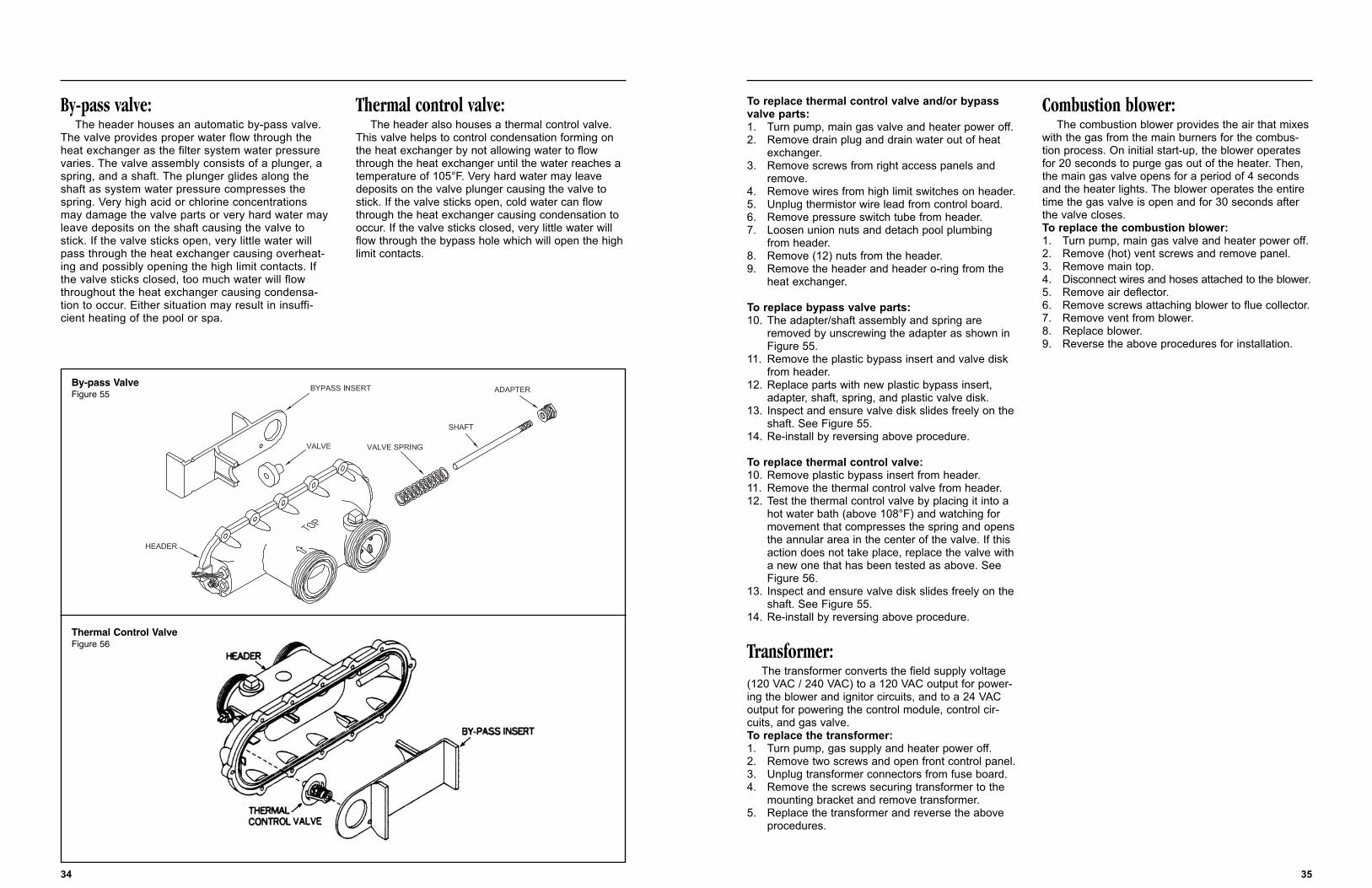
To replace thermal control valve and/or bypassvalve parts:1. Turn pump, main gas valve and heater power off.2. Remove drain plug and drain water out of heat
exchanger.3. Remove screws from right access panels and
remove.4. Remove wires from high limit switches on header.5. Unplug thermistor wire lead from control board.6. Remove pressure switch tube from header.7. Loosen union nuts and detach pool plumbing
from header.8. Remove (12) nuts from the header.9. Remove the header and header o-ring from the
heat exchanger.
To replace bypass valve parts:10. The adapter/shaft assembly and spring are
removed by unscrewing the adapter as shown in Figure 55.
11. Remove the plastic bypass insert and valve disk from header.
12. Replace parts with new plastic bypass insert, adapter, shaft, spring, and plastic valve disk.
13. Inspect and ensure valve disk slides freely on theshaft. See Figure 55.
14. Re-install by reversing above procedure.
To replace thermal control valve:10. Remove plastic bypass insert from header. 11. Remove the thermal control valve from header.12. Test the thermal control valve by placing it into a
hot water bath (above 108°F) and watching for movement that compresses the spring and opensthe annular area in the center of the valve. If this action does not take place, replace the valve witha new one that has been tested as above. See Figure 56.
13. Inspect and ensure valve disk slides freely on theshaft. See Figure 55.
14. Re-install by reversing above procedure.
Transformer:The transformer converts the field supply voltage
(120 VAC / 240 VAC) to a 120 VAC output for power-ing the blower and ignitor circuits, and to a 24 VACoutput for powering the control module, control cir-cuits, and gas valve.To replace the transformer:1. Turn pump, gas supply and heater power off.2. Remove two screws and open front control panel.3. Unplug transformer connectors from fuse board.4. Remove the screws securing transformer to the
mounting bracket and remove transformer.5. Replace the transformer and reverse the above
procedures.
Combustion blower:The combustion blower provides the air that mixes
with the gas from the main burners for the combus-tion process. On initial start-up, the blower operatesfor 20 seconds to purge gas out of the heater. Then,the main gas valve opens for a period of 4 secondsand the heater lights. The blower operates the entiretime the gas valve is open and for 30 seconds afterthe valve closes.To replace the combustion blower:1. Turn pump, main gas valve and heater power off.2. Remove (hot) vent screws and remove panel.3. Remove main top.4. Disconnect wires and hoses attached to the blower.5. Remove air deflector.6. Remove screws attaching blower to flue collector.7. Remove vent from blower.8. Replace blower.9. Reverse the above procedures for installation.
35
By-pass valve:The header houses an automatic by-pass valve.
The valve provides proper water flow through theheat exchanger as the filter system water pressurevaries. The valve assembly consists of a plunger, aspring, and a shaft. The plunger glides along theshaft as system water pressure compresses thespring. Very high acid or chlorine concentrationsmay damage the valve parts or very hard water mayleave deposits on the shaft causing the valve tostick. If the valve sticks open, very little water willpass through the heat exchanger causing overheat-ing and possibly opening the high limit contacts. Ifthe valve sticks closed, too much water will flowthroughout the heat exchanger causing condensa-tion to occur. Either situation may result in insuffi-cient heating of the pool or spa.
Thermal control valve:The header also houses a thermal control valve.
This valve helps to control condensation forming onthe heat exchanger by not allowing water to flowthrough the heat exchanger until the water reaches atemperature of 105°F. Very hard water may leavedeposits on the valve plunger causing the valve tostick. If the valve sticks open, cold water can flowthrough the heat exchanger causing condensation tooccur. If the valve sticks closed, very little water willflow through the bypass hole which will open the highlimit contacts.
34
By-pass ValveFigure 55
Thermal Control ValveFigure 56
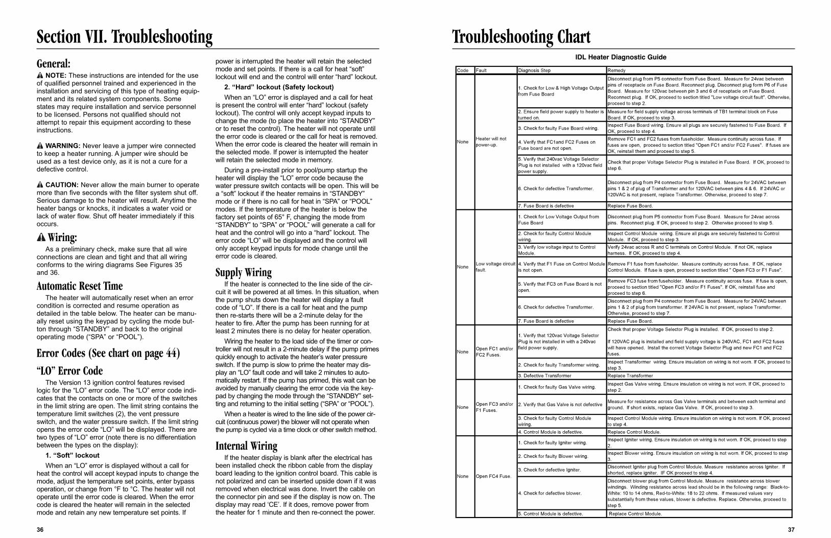
Troubleshooting Chart
37
Section VII. TroubleshootingGeneral:
NOTE: These instructions are intended for the useof qualified personnel trained and experienced in theinstallation and servicing of this type of heating equip-ment and its related system components. Somestates may require installation and service personnelto be licensed. Persons not qualified should notattempt to repair this equipment according to theseinstructions.
WARNING: Never leave a jumper wire connectedto keep a heater running. A jumper wire should beused as a test device only, as it is not a cure for adefective control.
CAUTION: Never allow the main burner to operatemore than five seconds with the filter system shut off.Serious damage to the heater will result. Anytime theheater bangs or knocks, it indicates a water void orlack of water flow. Shut off heater immediately if thisoccurs.
Wiring:As a preliminary check, make sure that all wire
connections are clean and tight and that all wiringconforms to the wiring diagrams See Figures 35 and 36.
Automatic Reset TimeThe heater will automatically reset when an error
condition is corrected and resume operation asdetailed in the table below. The heater can be manu-ally reset using the keypad by cycling the mode but-ton through “STANDBY” and back to the originaloperating mode (“SPA” or “POOL”).
Error Codes (See chart on page 44)“LO” Error Code
The Version 13 ignition control features revisedlogic for the “LO” error code. The “LO” error code indi-cates that the contacts on one or more of the switchesin the limit string are open. The limit string contains thetemperature limit switches (2), the vent pressureswitch, and the water pressure switch. If the limit stringopens the error code “LO” will be displayed. There aretwo types of “LO” error (note there is no differentiationbetween the types on the display):
1. “Soft” lockoutWhen an “LO” error is displayed without a call for
heat the control will accept keypad inputs to change themode, adjust the temperature set points, enter bypassoperation, or change from °F to °C. The heater will notoperate until the error code is cleared. When the errorcode is cleared the heater will remain in the selectedmode and retain any new temperature set points. If
power is interrupted the heater will retain the selectedmode and set points. If there is a call for heat “soft”lockout will end and the control will enter “hard” lockout.
2. “Hard” lockout (Safety lockout)When an “LO” error is displayed and a call for heat
is present the control will enter “hard” lockout (safetylockout). The control will only accept keypad inputs tochange the mode (to place the heater into “STANDBY”or to reset the control). The heater will not operate untilthe error code is cleared or the call for heat is removed.When the error code is cleared the heater will remain inthe selected mode. If power is interrupted the heaterwill retain the selected mode in memory.
During a pre-install prior to pool/pump startup theheater will display the “LO” error code because thewater pressure switch contacts will be open. This will bea “soft” lockout if the heater remains in “STANDBY”mode or if there is no call for heat in “SPA” or “POOL”modes. If the temperature of the heater is below thefactory set points of 65° F, changing the mode from“STANDBY” to “SPA” or “POOL” will generate a call forheat and the control will go into a “hard” lockout. Theerror code “LO” will be displayed and the control willonly accept keypad inputs for mode change until theerror code is cleared.
Supply WiringIf the heater is connected to the line side of the cir-
cuit it will be powered at all times. In this situation, whenthe pump shuts down the heater will display a faultcode of “LO”. If there is a call for heat and the pumpthen re-starts there will be a 2-minute delay for theheater to fire. After the pump has been running for atleast 2 minutes there is no delay for heater operation.
Wiring the heater to the load side of the timer or con-troller will not result in a 2-minute delay if the pump primesquickly enough to activate the heater’s water pressureswitch. If the pump is slow to prime the heater may dis-play an “LO” fault code and will take 2 minutes to auto-matically restart. If the pump has primed, this wait can beavoided by manually clearing the error code via the key-pad by changing the mode through the “STANDBY” set-ting and returning to the initial setting (“SPA” or “POOL”).
When a heater is wired to the line side of the power cir-cuit (continuous power) the blower will not operate whenthe pump is cycled via a time clock or other switch method.
Internal WiringIf the heater display is blank after the electrical has
been installed check the ribbon cable from the displayboard leading to the ignition control board. This cable isnot polarized and can be inserted upside down if it wasremoved when electrical was done. Invert the cable onthe connector pin and see if the display is now on. Thedisplay may read ‘CE’. If it does, remove power fromthe heater for 1 minute and then re-connect the power.
36
Code Fault Diagnosis Step Remedy
1. Check for Low & High Voltage Output from Fuse Board
Disconnect plug from P5 connector from Fuse Board. Measure for 24vac between pins of receptacle on Fuse Board. Reconnect plug. Disconnect plug form P6 of Fuse Board. Measure for 120vac between pin 3 and 6 of receptacle on Fuse Board. Reconnect plug. If OK, proceed to section titled "Low voltage circuit fault". Otherwise, proceed to step 2.
2. Ensure field power supply to heater is turned on.
Measure for field supply voltage across terminals of TB1 terminal block on Fuse Board. If OK, proceed to step 3.
3. Check for faulty Fuse Board wiring. Inspect Fuse Board wiring. Ensure all plugs are securely fastened to Fuse Board. If OK, proceed to step 4.
4. Verify that FC1and FC2 Fuses on Fuse board are not open.
Remove FC1 and FC2 fuses from fuseholder. Measure continuity across fuse. If fuses are open, proceed to section titled "Open FC1 and/or FC2 Fuses". If fuses are OK, reinstall them and proceed to step 5.
5. Verify that 240vac Voltage Selector Plug is not installed with a 120vac field power supply.
Check that proper Voltage Selector Plug is installed in Fuse Board. If OK, proceed to step 6.
6. Check for defective Transformer.Disconnect plug from P4 connector from Fuse Board. Measure for 24VAC between pins 1 & 2 of plug of Transformer and for 120VAC between pins 4 & 6. If 24VAC or 120VAC is not present, replace Transformer. Otherwise, proceed to step 7.
7. Fuse Board is defective Replace Fuse Board.
1. Check for Low Voltage Output from Fuse Board
Disconnect plug from P5 connector from Fuse Board. Measure for 24vac across pins. Reconnect plug. If OK, proceed to step 2. Otherwise proceed to step 5.
2. Check for faulty Control Module wiring.
Inspect Control Module wiring. Ensure all plugs are securely fastened to Control Module. If OK, proceed to step 3.
3. Verify low voltage input to Control Module.
Verify 24vac across R and C terminals on Control Module. If not OK, replace harness. If OK, proceed to step 4.
4. Verify that F1 Fuse on Control Module is not open.
Remove F1 fuse from fuseholder. Measure continuity across fuse. If OK, replace Control Module. If fuse is open, proceed to section titled " Open FC3 or F1 Fuse".
5. Verify that FC3 on Fuse Board is not open.
Remove FC3 fuse from fuseholder. Measure continuity across fuse. If fuse is open, proceed to section titled "Open FC3 and/or F1 Fuses". If OK, reinstall fuse and proceed to step 6.
6. Check for defective Transformer.Disconnect plug from P4 connector from Fuse Board. Measure for 24VAC between pins 1 & 2 of plug from transformer. If 24VAC is not present, replace Transformer. Otherwise, proceed to step 7.
7. Fuse Board is defective Replace Fuse Board.
1. Verify that 120vac Voltage Selector Plug is not installed in with a 240vac field power supply.
Check that proper Voltage Selector Plug is installed. If OK, proceed to step 2.
If 120VAC plug is installed and field supply voltage is 240VAC, FC1 and FC2 fuses will have opened. Install the correct Voltage Selector Plug and new FC1 and FC2 fuses.
2. Check for faulty Transformer wiring. Inspect Transformer wiring. Ensure insulation on wiring is not worn. If OK, proceed to step 3.
3. Defective Transformer Replace Transformer
1. Check for faulty Gas Valve wiring. Inspect Gas Valve wiring. Ensure insulation on wiring is not worn. If OK, proceed to step 2.
2. Verify that Gas Valve is not defective Measure for resistance across Gas Valve terminals and between each terminal and ground. If short exists, replace Gas Valve. If OK, proceed to step 3.
3. Check for faulty Control Module wiring.
Inspect Control Module wiring. Ensure insulation on wiring is not worn. If OK, proceed to step 4.
4. Control Module is defective. Replace Control Module.
1. Check for faulty Igniter wiring. Inspect Igniter wiring. Ensure insulation on wiring is not worn. If OK, proceed to step 2.
2. Check for faulty Blower wiring. Inspect Blower wiring. Ensure insulation on wiring is not worn. If OK, proceed to step 3.
3. Check for defective Igniter. Disconnect Igniter plug from Control Module. Measure resistance across Igniter. If shorted, replace igniter. IF OK proceed to step 4.
4. Check for defective blower.
Disconnect blower plug from Control Module. Measure resistance across blower windings. Winding resistance across lead should be in the following range: Black-to-White: 10 to 14 ohms, Red-to-White: 18 to 22 ohms. If measured values vary substantially from these values, blower is defective. Replace. Otherwise, proceed to step 5.
5. Control Module is defective. Replace Control Module.
None Open FC4 Fuse.
None Open FC1 and/or FC2 Fuses.
None Open FC3 and/or F1 Fuses.
None Heater will not power-up.
None Low voltage circuit fault.
IDL Heater Diagnostic Guide
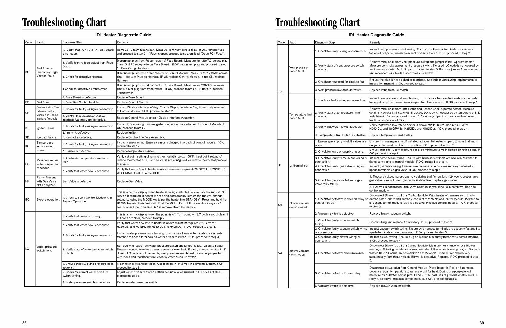
Troubleshooting Chart
39
Troubleshooting Chart
38
Code Fault Diagnosis Step Remedy
1. Verify that FC4 Fuse on Fuse Board is not open.
Remove FC from fuseholder. Measure continuity across fuse. If OK, reinstall fuse and proceed to step 2. If Fuse is open, proceed to section titled "Open FC4 Fuse".
2. Verify high voltage output from Fuse Board.
Disconnect plug from P6 connector of Fuse Board. Measure for 120VAC across pins 3 and 5 of P6 receptacle on Fuse Board. If OK, reconnect plug and proceed to step 3. If not OK, go to step 4.
3. Check for defective Harness.Disconnect plug from E10 connector of Control Module. Measure for 120VAC across pins 1 and 3 of Plug on Harness. IF OK replace Control Module. If not OK, replace Harness.
4.Check for defective Transformer.Disconnect plug from P4 connector of Fuse Board. Measure for 120VAC between pins 4 & 6 of plug from transformer . If OK, proceed to step 5. IF not OK, replace Transformer.
5. Fuse Board is defective Replace Fuse Board.EE Bad Board 1. Defective Control Module Replace Control Module.
1. Check for faulty wiring or connection. Inspect Display Interface Wiring. Ensure Display Interface Plug is securely attached to Control Module. If OK, proceed to step 2.
2. Control Module and/or Display Interface Assembly are defective. Replace Control Module and/or Display Interface Assembly.
1. Check for faulty wiring or connection. Inspect Igniter wiring. Ensure Igniter Plug is securely attached to Control Module. If OK, proceed to step 2.
2. Igniter is defective. Replace Igniter.SB Keypad Failure 1. Keypad is defective. Replace Display Interface Assembly.
1. Check for faulty wiring or connection. Inspect sensor wiring. Ensure sensor is plugged into back of control module. If OK, proceed to step 2.
2. Sensor is defective. Replace temperature sensor.
1. Pool water temperature exceeds 108°F.
Verify set point setting of remote thermostat is below 108°F. If set point setting of remote thermostat is OK, or if heater is not configured for remote thermostat proceed to step 2.
2. Verify that water flow is adequate Verify that water flow to heater is above minimum required (25 GPM for H250IDL, & 40 GPM for H350IDL & H400IDL).
HFFlame Present with Gas Valve Not Energized.
Gas Valve is defective. Replace Gas Valve.
BO Bypass operation. 1. Check to see if Control Module is in Bypass Operation.
This is a normal display when heater is being controlled by a remote thermostat. No service is required. If heater is not being controlled by remote thermostat, change setting by using the MODE key to put the heater into STANDBY. Press and hold the DOWN key and then press and hold the MODE key. HOLD down both keys for 3 seconds until the indication "bo" is removed from the display.
1. Verify that pump is running. This is a normal display when the pump is off. Turn pump on. LO code should clear. If LO does not clear, proceed to step 2.
2. Verify that water flow is adequate Verify that water flow rate to heater is above minimum required (25 GPM for H250IDL, and 40 GPM for H350IDL and H400IDL). If OK, proceed to step 3.
3. Check for faulty wiring or connection. Inspect water pressure switch wiring. Ensure wire harness terminals are securely fastened to spade terminals on water pressure switch. If OK, proceed to step 4.
4. Verify state of water pressure switch contacts.
Remove wire leads from water pressure switch and jumper leads. Operate heater. Measure continuity across water pressure switch fault. If open, proceed to step 5. If closed, LO code is not caused by vent pressure switch fault. Remove jumper from wire leads and reconnect wire leads to water pressure switch.
5. Ensure that low pump pressure does not exist.
Clean filter or clear blockages. Check position of valves in plumbing system. If OK proceed to step 6.
5. Check for correct water pressure switch setting.
Adjust water pressure switch setting per installation manual. If LO does not clear, proceed to step 6.
6. Water pressure switch is defective. Replace water pressure switch.
Water pressure switch fault.LO
SFTemperature sensor input failure.
HSMaximum return water temperature exceeded.
CE
Communication Error Between Control Module and Display Interface Assembly
IO Igniter Failure
BDBad Board or Secondary High Voltage Fault
IDL Heater Diagnostic Guide IDL Heater Diagnostic GuideCode Fault Diagnosis Step Remedy
1. Check for faulty wiring or connection. Inspect vent pressure switch wiring. Ensure wire harness terminals are securely fastened to spade terminals on vent pressure switch. If OK, proceed to step 2.
2. Verify state of vent pressure switch contacts.
Remove wire leads from vent pressure switch and jumper leads. Operate heater. Measure continuity across vent pressure switch. If closed, LO code is not caused by vent pressure switch fault. If open, proceed to step 3. Remove jumper from wire leads and reconnect wire leads to vent pressure switch.
3. Check for restricted for blocked flue. Ensure that flue is not blocked or restricted. See indoor vent sizing requirements in installation manual. If OK, proceed to step 4.
4. Vent pressure switch is defective. Replace vent pressure switch.
1.Check for faulty wiring or connection. Inspect temperature limit switch wiring. Ensure wire harness terminals are securely fastened to spade terminals on temperature limit switches. If OK, proceed to step 2.
2. Verify state of temperature limits’ contacts.
Remove wire leads from limit switch and jumper leads. Operate heater. Measure continuity across limit switches. If closed, LO code is not caused by temperature limit switch fault. If open, proceed to step 3. Remove jumper from leads and reconnect leads to temperature limits.
3. Verify that water flow is adequate Verify that water flow rate to heater is above minimum required (25 GPM for H250IDL, and 40 GPM for H350IDL and H400IDL). If OK, proceed to step 4.
4. Temperature limit switch is defective. Replace temperature limit switch.
1. Ensure gas supply shutoff valves are open.
Ensure that main gas shutoff installed adjacent to heater is open. Ensure that knob on gas valve inside unit is in on position. If OK, proceed to step 2.
2. Check for low gas supply pressure. Ensure inlet gas supply pressure exceeds minimum valve indicated on rating plate. If OK, proceed to step 3.
3. Check for faulty flame sense wiring or connection.
Inspect flame sense wiring. Ensure wire harness terminals are securely fastened to flame sense and to control module. If OK, proceed to step 4.
4. Check for faulty gas valve wiring or connection.
Inspect gas valve wiring. Ensure wire harness terminals are securely fastened to spade terminals on gas valve. If OK, proceed to step 5.
1. Measure voltage across gas valve during trial for ignition. If 24 vac is present and gas valve does not open, gas valve is defective. Replace gas valve.
2. If 24 vac is not present, gas valve relay on control module is defective. Replace control module.
1. Check for defective blower on relay or control module.
Disconnect Blower plug from Control Module. With heater off, measure continuity across pins 1 and 2 and across 2 and 3 of receptacle on Control Module. If either pair is closed, control module relay is defective. Replace control module. If OK, proceed to step 2.
2. Vacuum switch is defective. Replace blower vacuum switch.
1. Check for faulty vacuum switch tubing. Check tubing and replace if necessary. If OK, proceed to step 2.
2. Check for faulty vacuum switch wiring or connection.
Inspect vacuum switch wring. Ensure wire harness terminals are securely fastened to spade terminals on vacuum switch. If Ok, proceed to step 3.
3. Check for faulty blower wiring or connection.
Inspect blower wiring. Ensure plug on blower is securely fastened to control module. If OK, proceed to step 4.
4. Check for defective vacuum switch.
Disconnect Blower plug from Control Module. Measure resistance across Blower windings. Winding resistance across lead should be in the following range: Black-to-White: 10 to 14 ohms, Red-to-White: 18 to 22 ohms. If measured values vary substantially from these values, Blower is defective. Replace. If OK, proceed to step 5.
5. Check for defective blower relay.
Disconnect blower plug from Control Module. Place heater in Pool or Spa mode. Lower set point temperature to generate call for heat. During pre-purge period, measure for 120VAC across pins 1 and 2. If 120VAC is not present, control module relay is defective. Replace control module. If OK, proceed to step 6.
6. Vacuum switch is defective. Replace blower vacuum switch.
Blower vacuum switch closed.
Blower vacuum switch open
5. Check for gas valve failure or gas valve relay failure.
Vent pressure switch fault.
Temperature limit switch fault.
Ignition failureIF
AC
AO
LO
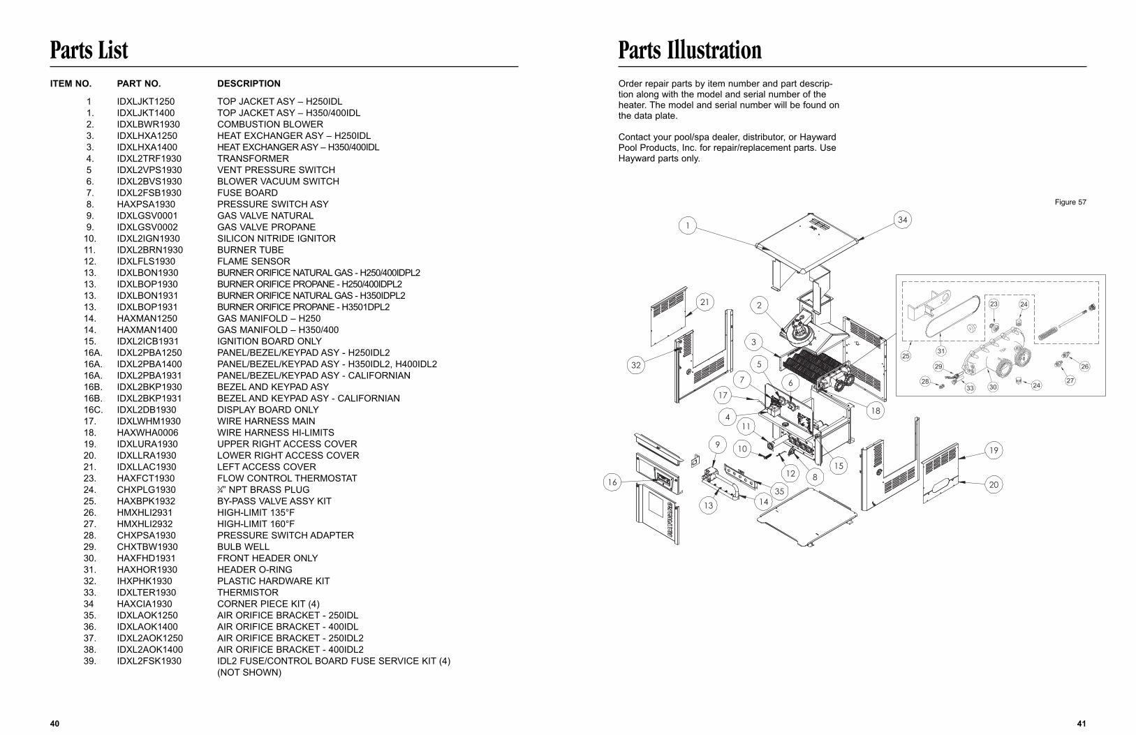
Parts List Parts IllustrationOrder repair parts by item number and part descrip-tion along with the model and serial number of theheater. The model and serial number will be found onthe data plate.
Contact your pool/spa dealer, distributor, or HaywardPool Products, Inc. for repair/replacement parts. UseHayward parts only.
ITEM NO. PART NO. DESCRIPTION
1 IDXLJKT1250 TOP JACKET ASY – H250IDL1. IDXLJKT1400 TOP JACKET ASY – H350/400IDL2. IDXLBWR1930 COMBUSTION BLOWER3. IDXLHXA1250 HEAT EXCHANGER ASY – H250IDL3. IDXLHXA1400 HEAT EXCHANGER ASY – H350/400IDL4. IDXL2TRF1930 TRANSFORMER5 IDXL2VPS1930 VENT PRESSURE SWITCH6. IDXL2BVS1930 BLOWER VACUUM SWITCH7. IDXL2FSB1930 FUSE BOARD8. HAXPSA1930 PRESSURE SWITCH ASY9. IDXLGSV0001 GAS VALVE NATURAL9. IDXLGSV0002 GAS VALVE PROPANE
10. IDXL2IGN1930 SILICON NITRIDE IGNITOR11. IDXL2BRN1930 BURNER TUBE12. IDXLFLS1930 FLAME SENSOR13. IDXLBON1930 BURNER ORIFICE NATURAL GAS - H250/400IDPL213. IDXLBOP1930 BURNER ORIFICE PROPANE - H250/400IDPL213. IDXLBON1931 BURNER ORIFICE NATURAL GAS - H350IDPL213. IDXLBOP1931 BURNER ORIFICE PROPANE - H3501DPL214. HAXMAN1250 GAS MANIFOLD – H25014. HAXMAN1400 GAS MANIFOLD – H350/40015. IDXL2ICB1931 IGNITION BOARD ONLY16A. IDXL2PBA1250 PANEL/BEZEL/KEYPAD ASY - H250IDL216A. IDXL2PBA1400 PANEL/BEZEL/KEYPAD ASY - H350IDL2, H400IDL216A. IDXL2PBA1931 PANEL/BEZEL/KEYPAD ASY - CALIFORNIAN16B. IDXL2BKP1930 BEZEL AND KEYPAD ASY16B. IDXL2BKP1931 BEZEL AND KEYPAD ASY - CALIFORNIAN16C. IDXL2DB1930 DISPLAY BOARD ONLY17. IDXLWHM1930 WIRE HARNESS MAIN18. HAXWHA0006 WIRE HARNESS HI-LIMITS19. IDXLURA1930 UPPER RIGHT ACCESS COVER20. IDXLLRA1930 LOWER RIGHT ACCESS COVER21. IDXLLAC1930 LEFT ACCESS COVER23. HAXFCT1930 FLOW CONTROL THERMOSTAT24. CHXPLG1930 3⁄4” NPT BRASS PLUG25. HAXBPK1932 BY-PASS VALVE ASSY KIT26. HMXHLI2931 HIGH-LIMIT 135°F27. HMXHLI2932 HIGH-LIMIT 160°F28. CHXPSA1930 PRESSURE SWITCH ADAPTER29. CHXTBW1930 BULB WELL30. HAXFHD1931 FRONT HEADER ONLY31. HAXHOR1930 HEADER O-RING32. IHXPHK1930 PLASTIC HARDWARE KIT33. IDXLTER1930 THERMISTOR34 HAXCIA1930 CORNER PIECE KIT (4)35. IDXLAOK1250 AIR ORIFICE BRACKET - 250IDL36. IDXLAOK1400 AIR ORIFICE BRACKET - 400IDL37. IDXL2AOK1250 AIR ORIFICE BRACKET - 250IDL238. IDXL2AOK1400 AIR ORIFICE BRACKET - 400IDL239. IDXL2FSK1930 IDL2 FUSE/CONTROL BOARD FUSE SERVICE KIT (4)
(NOT SHOWN)
40 41
Figure 57
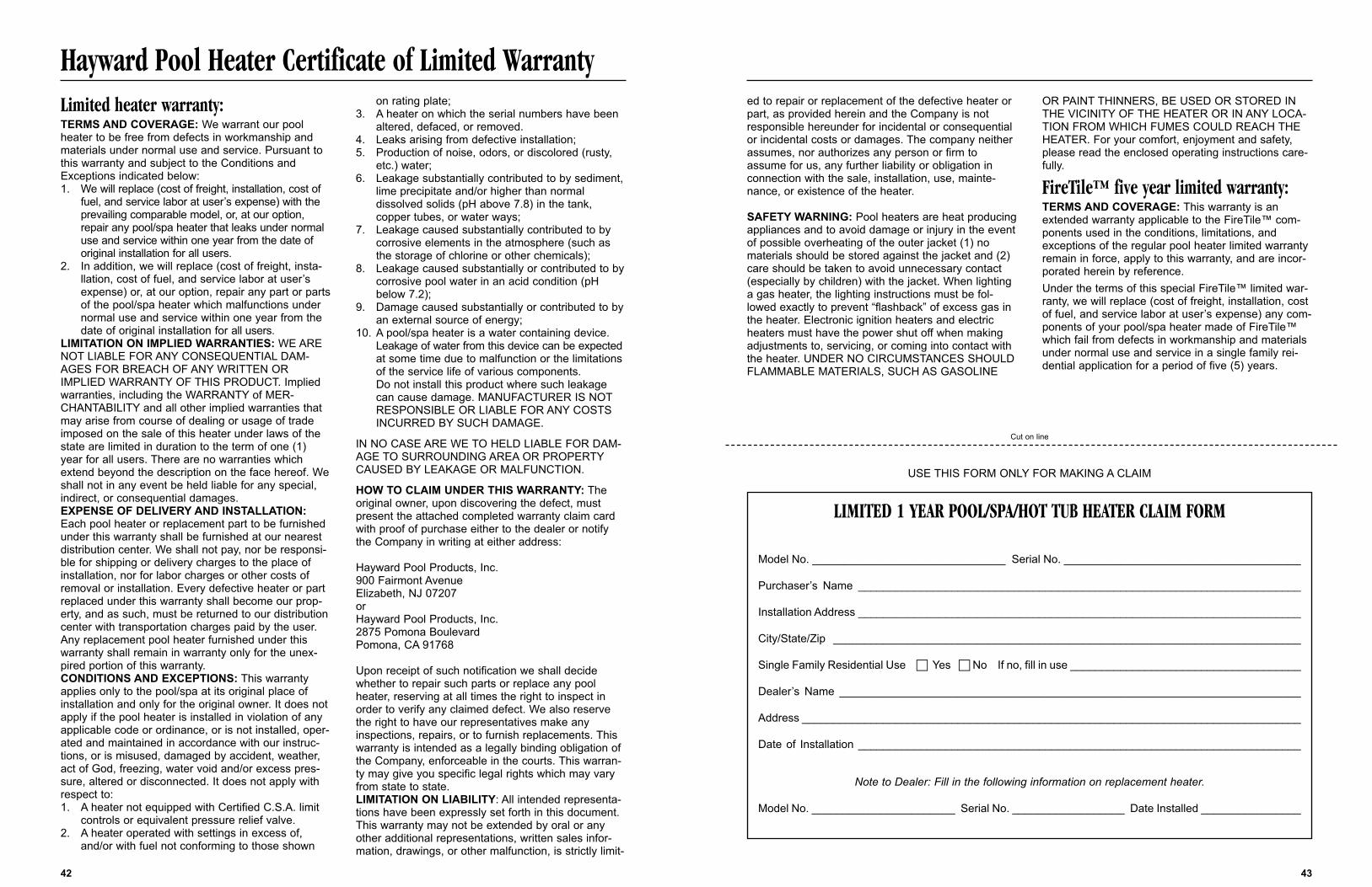
ed to repair or replacement of the defective heater orpart, as provided herein and the Company is notresponsible hereunder for incidental or consequentialor incidental costs or damages. The company neitherassumes, nor authorizes any person or firm toassume for us, any further liability or obligation inconnection with the sale, installation, use, mainte-nance, or existence of the heater.
SAFETY WARNING: Pool heaters are heat producingappliances and to avoid damage or injury in the eventof possible overheating of the outer jacket (1) nomaterials should be stored against the jacket and (2)care should be taken to avoid unnecessary contact(especially by children) with the jacket. When lightinga gas heater, the lighting instructions must be fol-lowed exactly to prevent “flashback” of excess gas inthe heater. Electronic ignition heaters and electricheaters must have the power shut off when makingadjustments to, servicing, or coming into contact withthe heater. UNDER NO CIRCUMSTANCES SHOULDFLAMMABLE MATERIALS, SUCH AS GASOLINE
OR PAINT THINNERS, BE USED OR STORED INTHE VICINITY OF THE HEATER OR IN ANY LOCA-TION FROM WHICH FUMES COULD REACH THEHEATER. For your comfort, enjoyment and safety,please read the enclosed operating instructions care-fully.
FireTile™ five year limited warranty: TERMS AND COVERAGE: This warranty is anextended warranty applicable to the FireTile™ com-ponents used in the conditions, limitations, andexceptions of the regular pool heater limited warrantyremain in force, apply to this warranty, and are incor-porated herein by reference.Under the terms of this special FireTile™ limited war-ranty, we will replace (cost of freight, installation, costof fuel, and service labor at user’s expense) any com-ponents of your pool/spa heater made of FireTile™which fail from defects in workmanship and materialsunder normal use and service in a single family rei-dential application for a period of five (5) years.
43
Hayward Pool Heater Certificate of Limited WarrantyLimited heater warranty:TERMS AND COVERAGE: We warrant our poolheater to be free from defects in workmanship andmaterials under normal use and service. Pursuant tothis warranty and subject to the Conditions andExceptions indicated below:1. We will replace (cost of freight, installation, cost of
fuel, and service labor at user’s expense) with the prevailing comparable model, or, at our option, repair any pool/spa heater that leaks under normal use and service within one year from the date of original installation for all users.
2. In addition, we will replace (cost of freight, insta-llation, cost of fuel, and service labor at user’s expense) or, at our option, repair any part or partsof the pool/spa heater which malfunctions under normal use and service within one year from the date of original installation for all users.
LIMITATION ON IMPLIED WARRANTIES: WE ARENOT LIABLE FOR ANY CONSEQUENTIAL DAM-AGES FOR BREACH OF ANY WRITTEN ORIMPLIED WARRANTY OF THIS PRODUCT. Impliedwarranties, including the WARRANTY of MER-CHANTABILITY and all other implied warranties thatmay arise from course of dealing or usage of tradeimposed on the sale of this heater under laws of thestate are limited in duration to the term of one (1)year for all users. There are no warranties whichextend beyond the description on the face hereof. Weshall not in any event be held liable for any special,indirect, or consequential damages.EXPENSE OF DELIVERY AND INSTALLATION:Each pool heater or replacement part to be furnishedunder this warranty shall be furnished at our nearestdistribution center. We shall not pay, nor be responsi-ble for shipping or delivery charges to the place ofinstallation, nor for labor charges or other costs ofremoval or installation. Every defective heater or partreplaced under this warranty shall become our prop-erty, and as such, must be returned to our distributioncenter with transportation charges paid by the user.Any replacement pool heater furnished under thiswarranty shall remain in warranty only for the unex-pired portion of this warranty.CONDITIONS AND EXCEPTIONS: This warrantyapplies only to the pool/spa at its original place ofinstallation and only for the original owner. It does notapply if the pool heater is installed in violation of anyapplicable code or ordinance, or is not installed, oper-ated and maintained in accordance with our instruc-tions, or is misused, damaged by accident, weather,act of God, freezing, water void and/or excess pres-sure, altered or disconnected. It does not apply withrespect to:1. A heater not equipped with Certified C.S.A. limit
controls or equivalent pressure relief valve.2. A heater operated with settings in excess of,
and/or with fuel not conforming to those shown
on rating plate;3. A heater on which the serial numbers have been
altered, defaced, or removed.4. Leaks arising from defective installation;5. Production of noise, odors, or discolored (rusty,
etc.) water;6. Leakage substantially contributed to by sediment,
lime precipitate and/or higher than normal dissolved solids (pH above 7.8) in the tank, copper tubes, or water ways;
7. Leakage caused substantially contributed to by corrosive elements in the atmosphere (such as the storage of chlorine or other chemicals);
8. Leakage caused substantially or contributed to bycorrosive pool water in an acid condition (pH below 7.2);
9. Damage caused substantially or contributed to byan external source of energy;
10. A pool/spa heater is a water containing device. Leakage of water from this device can be expectedat some time due to malfunction or the limitations of the service life of various components. Do not install this product where such leakage can cause damage. MANUFACTURER IS NOTRESPONSIBLE OR LIABLE FOR ANY COSTS INCURRED BY SUCH DAMAGE.
IN NO CASE ARE WE TO HELD LIABLE FOR DAM-AGE TO SURROUNDING AREA OR PROPERTYCAUSED BY LEAKAGE OR MALFUNCTION.
HOW TO CLAIM UNDER THIS WARRANTY: Theoriginal owner, upon discovering the defect, mustpresent the attached completed warranty claim cardwith proof of purchase either to the dealer or notifythe Company in writing at either address:
Hayward Pool Products, Inc.900 Fairmont AvenueElizabeth, NJ 07207orHayward Pool Products, Inc.2875 Pomona BoulevardPomona, CA 91768
Upon receipt of such notification we shall decidewhether to repair such parts or replace any poolheater, reserving at all times the right to inspect inorder to verify any claimed defect. We also reservethe right to have our representatives make anyinspections, repairs, or to furnish replacements. Thiswarranty is intended as a legally binding obligation ofthe Company, enforceable in the courts. This warran-ty may give you specific legal rights which may varyfrom state to state.LIMITATION ON LIABILITY: All intended representa-tions have been expressly set forth in this document.This warranty may not be extended by oral or anyother additional representations, written sales infor-mation, drawings, or other malfunction, is strictly limit-
42
LIMITED 1 YEAR POOL/SPA/HOT TUB HEATER CLAIM FORM
Model No. _______________________________ Serial No. ______________________________________
Purchaser’s Name _______________________________________________________________________
Installation Address _______________________________________________________________________
City/State/Zip ___________________________________________________________________________
Single Family Residential Use c Yes c No If no, fill in use _____________________________________
Dealer’s Name __________________________________________________________________________
Address ________________________________________________________________________________
Date of Installation _______________________________________________________________________
Note to Dealer: Fill in the following information on replacement heater.
Model No. _______________________ Serial No. __________________ Date Installed ________________
USE THIS FORM ONLY FOR MAKING A CLAIM
Cut on line
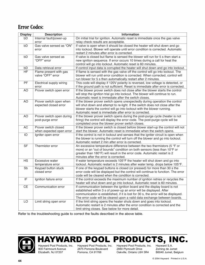
HAYWARD POOL PRODUCTS, INC.Hayward Pool Products, Inc.900 Fairmount AvenueElizabeth, NJ 07207
Hayward Pool Products, Inc.2875 Pomona BoulevardPomona, CA 91768
Hayward Pool Products, Inc.2880 Plymouth DriveOakville, Ontario L6H 5R4
Hayward S.A.Zoming de JumetB6040 Jumet, Belgium
© 2004 Hayward Printed in U.S.A.44
Error Codes:
Refer to the troubleshooting guide to correct the faults described in the above table.