Embed Size (px)
Citation preview

INSTALLATION, OPERATION & MAINTENANCE MANUAL
FOLLOW THIS MANUAL CAREFULLY TO ENSURE THE MACHINE WILL FUNCTION CORRECTLY AND PROVIDE MANY YEARS OF DEPENDABLE SERVICE. FAILURE TO FOLLOW THESE INSTRUCTIONS AND SAFETY WARNINGS MAY RESULT IN PERSONAL INJURY OR PROPERTY DAMAGE. KEEP THIS MANUAL IN A SAFE DRY PLACE FOR FUTURE REFERENCE.
MODELS:HD2P-13KCL13,000 LB CAPACITY 2 POST LIFT
®
Products May Be Upgraded Without Notice
Please Visit
WWW.TITANLIFTS.COM
For The Latest Version Of This Manual
P.O. Box 7069 • Greenwood, IN 46142 • Ph. 888-908-4826 • Fx. 317-215-2770 • www.titanlifts.com

PO Box 7069 Greenwood, IN 461421.888.908-4826 FAX (317) 215.2770
www.titanlifts.com
TITAN MARKETING, LLC
®
To Our Valued Customers:
Thank you for purchasing a Titan Lifts® product. We hope this high quality equipment provides you with years of dependable service.
It is unfortunate that rare situations may occur with the products you purchase from Titan Lifts®. We value your business as well as the trust you have and need to maintain your relationship with us. Titan Lifts® carries liability coverage that may protect our customers if a situation does occur. However, as in all accidents there must be proof of liability for a claim to be made. Our insurance company requires the following procedures be observed in order to consider a claim:
A. The claimant must contact the Titan Lifts® distributor immediately with the facts of the situation. B. If any equipment is damaged, including vehicles or shop equipment, Titan Lifts® must be given the opportunity to send an impartial representative to the site for proper assessment of the situation. C. The Vehicle cannot be moved until either an impartial representative has reviewed the accident or clear and precise pictures are taken that reflect all the pertinent information for an impartial representative to be able to access the information from a distance. Titan Lifts® or its representatives must approve the pictures before anything can be moved. D. If any potential liability is determined on behalf of Titan Lifts®, two estimates must be submitted for damages to be reimbursed.
It is imperative that the claimant complies with these procedures, because without proper assessment of the situation a claim will be denied.
ARBITRATION NOTICEThe installation or use of this equipment shall constitute an acknowledgment that the user agrees to resolve any and all disputes or claims of any kind whatsoever, which relate in any way to the equipment, by way of binding arbitration, not litigation. No suit or legal action may be filed in any state or federal court. Any arbitration shall be governed by the Federal Arbitration Act, and administered by the American Mediation Association, Indianapolis Indiana. The maximum amount that an arbitrator may award and all damages shall not exceed the retail value of this equipment.
WARRANTY NOTICEThis equipment must be assembled and used in the manner according to the documentation provided to be covered by warranty.
Damaged or missing components must be reported within 72 hours of receipt to your freight carrier and to the distributor. Claims must be filed to cover cost.
If you have any questions or if we can be of any further assistance, please don’t hesitate to contact a Titan Lifts® representative at 1-888-908-4826. Thank you for the opportunity to continue to serve your lift equipment needs.

TABLE OF CONTENTS1-SAFETY ���������������������������������������������������������������������������������������������������������������� PAGE 1
1�1 INTRODUCTION �������������������������������������������������������������������������������������������������������������������PAGE 11�2 SAFETY INSTRUCTIONS FOR COMMISSIONING ����������������������������������������������������������������PAGE 11�3 SAFETY INSTRUCTIONS FOR OPERATION �������������������������������������������������������������������������PAGE 11�4 SAFETY INSTRUCTIONS FOR MAINTENANCE �������������������������������������������������������������������PAGE 31�5 RISKS �����������������������������������������������������������������������������������������������������������������������������������PAGE 3
2-DESCRIPTION ������������������������������������������������������������������������������������������������������ PAGE 43-UNPACKING & SETUP ������������������������������������������������������������������������������������������ PAGE 5
3�1 DELIVERY AND CHECK OF PACKAGES ��������������������������������������������������������������������������������PAGE 53�2 LIFTING AND HANDLING �����������������������������������������������������������������������������������������������������PAGE 53�3 PREPARATION ���������������������������������������������������������������������������������������������������������������������PAGE 5
4 SPECIFICATIONS ������������������������������������������������������������������������������������������������� PAGE 65-FLOOR REQUIREMENTS �������������������������������������������������������������������������������������� PAGE 6
5�1 SELECTING THE SITE AREA ������������������������������������������������������������������������������������������������PAGE 65�2 FLOOR REQUIREMENTS �������������������������������������������������������������������������������������������������������PAGE 65�3 IMPORTANT CONCRETE AND ANCHORING INFORMATION �����������������������������������������������PAGE 75�4 ANCHORING TIP SHEET ������������������������������������������������������������������������������������������������������PAGE 7
6-INSTALLATION INSTRUCTIONS ������������������������������������������������������������������������� PAGE 87-OPERATION INSTRUCTIONS ����������������������������������������������������������������������������� PAGE 12
7�1 DEFECTS / MALFUNCTIONS ����������������������������������������������������������������������������������������������PAGE 127�2 CONTROLS �������������������������������������������������������������������������������������������������������������������������PAGE 12
7.2.1 UP CONTROL .................................................................................................................. PAGE 127.2.2 SAFETY LOCK CONTROL ............................................................................................... PAGE 127.2.3 LOWERING CONTROL .................................................................................................... PAGE 13
7�3 OPERATION ������������������������������������������������������������������������������������������������������������������������PAGE 13
8-MAINTENANCE �������������������������������������������������������������������������������������������������� PAGE 158�1 MAINTENANCE SCHEDULE �����������������������������������������������������������������������������������������������PAGE 15
8.1.1 DAILY ............................................................................................................................... PAGE 158.1.2 WEEKLY ........................................................................................................................... PAGE 158.1.3 MONTHLY ....................................................................................................................... PAGE 168.1.4 BI-MONTHLY ................................................................................................................... PAGE 168.1.5 YEARLY ............................................................................................................................ PAGE 168.1.6 EVERY OTHER YEAR ...................................................................................................... PAGE 16
8�2 MAINTENANCE BY OPERATOR �����������������������������������������������������������������������������������������PAGE 178.2.1 HYDRAULIC SYSTEM ..................................................................................................... PAGE 178.2.2 GREASING POINTS ........................................................................................................ PAGE 178.2.3 OPERATION AND WEAR CHECKS ................................................................................. PAGE 188.2.4 LIFT STABILITY .............................................................................................................. PAGE 18
8�3 CLEANING ��������������������������������������������������������������������������������������������������������������������������PAGE 18
9-TROUBLESHOOTING ����������������������������������������������������������������������������������������� PAGE 1910-OWNER/EMPLOYER RESPONSIBILITIES �������������������������������������������������������� PAGE 2011-DIAGRAMS (FIG� 1-8) ��������������������������������������������������������������������������������������� PAGE 21

1
1-SAFETYINSTRUCTIONS
1.1 INTRODUCTION
• The lift may be installed and commissioned by authorized service personnel only.• The standard lift version may not be installed and commissioned in the vicinity of explosives or flammable liquids, outdoors or in moist rooms (e.g. car wash).
• Read this entire manual.• Load should not exceed rated capacity for this lift – 13,000 lb (3,250 lb per lift arm)• Only trained authorized personnel over the age of 18 years should operate the lift.• Indoor use recommended.• Always lift the vehicle using all four arms.• Never use the lift to raise one end or one side of vehicle.
FAILURE TO COMPLY WITH INSTRUCTIONS COULD RESULT IN PROPERTY DAMAGE.
WARNING: READ ENTIRE MANUAL AND COMPLY WITH ALL SAFETY AND SERVICE PRECAUTIONS. DEATH, PERSONAL INJURY AND / OR PROPERTY DAMAGE MAY OCCUR IF INSTRUCTIONS ARE NOT FOLLOWED CAREFULLY.
Personal injury and property damage incurred due to non-compliance with these safety instructions are not covered by the product liability regulations.
FAILURE TO COMPLY WITH INSTRUCTIONS COULD RESULT IN PERSONAL INJURY.
SYMBOLS
IMPORTANT INFORMATION
1.2 SAFETY INSTRUCTIONS FOR COMMISSIONING
1.3 SAFETY INSTRUCTIONS FOR OPERATION

2
WARNING: Prior to completely raising the vehicle, raise the vehicle 6” off the ground and check the adapter pads for solid contact by performing the “BUMPER TEST”. Walk around the back of the vehicle and push up and down on the bumper. The vehicle will rock, but should not at any time lose contact with the pads. If the vehicle is bouncing off the pads or feels at all unstable, you should lower it back to the ground and reposition the pads to balance the load. Repeat this process until the vehicle is completely stable.
WARNING: Use this lift only in well ventilated areas. Carbon monoxide exhausted from running vehicle engines is a colorless, odorless fume that, if inhaled, can cause serious personal injury or death.
WARNING: People with pacemakers should consult their physician(s) before using this product. Operation of electrical equipment in close proximity to a heart pacemaker could cause interference or failure of the pacemaker.
WARNING: This product contains or produces a chemical known to the State of California to cause cancer and birth defects (or other reproductive harm). (California Health & Safety Code 25249.5 et seq.)
• Maintain a safe working environment. The work area should be clean, dry, clutter free, and sufficiently lit.
• Vehicle doors should be closed during the raising and lowering cycles.• Closely watch the vehicle and lift during the raising and lowering cycles.• Do not operate the lift in explosive atmospheres, such as in the presence of flammable
liquids, gases, or dust. Power equipment can create sparks which may ignite flammables.• Keep hands, tools, and other extremities from under carriage and moving parts.• Never operate this lift with someone on it.• Do not allow anyone on the lift or inside a raised vehicle.• Keep children and bystanders away from work area. Do not let children operate or play on
lift.• Wear proper safety attire. Do not wear loose fitting clothing while operating lift. Long hair,
jewelry and sleeves should be secured.• Never leave the lift unattended while under a load.• Do not operate this lift if under the influence of drugs, alcohol, or medication. Operator
must be alert at all times when using heavy lift equipment.• Comply with all applicable accident prevention regulations.• Only use the vehicle manufacturer’s recommended lifting points.• After positioning the vehicle, apply the parking brake.• Use caution when removing or installing heavy vehicle components which may result in
center-of-gravity displacement.• Use this lift only for the work it is intended. Do not use this product for an application for
which it was not designed. Misuse can lead to personal injury and/or property damage.

3
• Maintenance or repair work should be done by authorized service personnel only.• Work on the electrical equipment should be done by certified licensed electricians only.• Ensure that ecologically harmful substances are disposed of in accordance with the
appropriate regulations.• To prevent the risk of damage, do not use high pressure / steam jet cleaners or caustic
cleaning agents.• Do not replace or override the safety devices.
WARNING: Risks the personnel could encounter, due to an improper use of the lift, are described in this section.
CRUSHING RISK
During lowering of runways and vehicles, personnel must not be within the area covered by the lowering trajectory. The operator must be sure no one is in danger before operating the lift. Stay clear of the lift when lowering or raising vehicles. Keep hands and feet away from moving parts and especially points that could pinch. Keep your feet clear of the lift when raising and lowering vehicles.
RISK OF THE VEHICLE FALLING FROM THE LIFT
Risk of the vehicle falling from the lift is increased: when the vehicle is improperly placed on the platforms, when the vehicle’s weight or physical dimensions exceed the rated capacity of the lift, or when there is excessive movement of the vehicle while on the lift. If vehicle appears to begin falling, exit the area as quickly as possible to avoid injury. Always position vehicle with the center of gravity midway between the adapters. Adding or removing parts of a vehicle on the lift will alter the weight displacement on the lift. Therefore, use of auxilary safety stands in the front and back of the vehicle is recommended. Never override the manufactured lift controls. Always use height adapter pads when possible to ensure proper contact. Only authorized personnel should be allowed in the lift area and the lift should only be operated by authorized and trained personnel. Adding or removing parts of a vehicle on the lift will alter the weight displacement on the lift.
BUMPING RISK
When the lift is stopped at relatively low working height, the risk of bumping against projecting parts increases. Always be aware of your surroundings and avoid bumping your head or body on the lift or the vehicle.
1.4 SAFETY INSTRUCTIONS FOR MAINTENANCE
1.5 RISKS

4
The following is a 2-Column hydraulic, leaf chain driven lift.The model numbers covered in this manual are designated below:
HD2P-13KCL: 2-Column Overhead Beam Lift type, 13,000 lb Capacity, Symmetric Swing Arm set up.
This lift is a 13,000 lb capacity, 2-Post Lift. The safety latch system is very similar to an extension ladder. The safety latch is in contact with the rack as the lift ascends and drops into place as the lift rises. Safety latch engages in rack in 3” increments at about 16” from the ground. The latch must be manually disengaged for the lift to descend. The latch is released by raising the latch rack using the hydraulic drive system and pulling the release handle. If the user lets go of the manual release handle, the safety latch will re-engage on the next lock latch it encounters. Heavy bearings and heavy-duty leaf chains are used throughout the lift. The work is done with the heavy-duty chain connected to a 4” cylinder, driven by a hydraulic pump capable of providing 3,000 psi.
Please read the Safety Procedures and operation instructions in this manual before operating the lift. Proper installation is very important. To minimize the chance of making an error in installation, please read this manual thoroughly before beginning installation. Check with building owner and/or architect’s building plans when applicable. The lift should be located on a level floor with 6” 3000 psi concrete sufficiently cured, for at least 30 days.
This is a vehicle lift installation / operation manual and no attempt is made or implied herein to instruct the user in lifting methods particular to an individual application. Rather, the contents of this manual are intended as a basis for operation and maintenance of the unit as it stands alone or as it is intended and anticipated to be used in conjunction with other equipment.
Proper application of the equipment described herein is limited to the parameters detailed in the specifications and the uses set forth in the descriptive passages. Any other proposed application of this equipment should be documented and submitted in writing to the factory for examination. The user assumes full responsibility for any equipment damage, personal injury, or alteration of the equipment described in this manual or any subsequent damages.
2-DESCRIPTION

5
3-UNPACKING & SETUP
Only skilled personnel who are familiar with the lift and this manual shall be allowed to carry out, lifting, handling, transport and unpacking operations.
When the lift is delivered, carefully unpack the lift making sure all the parts have been included. Check for possible damages due to transport and storage; verify that what is specified in the confirmation of order is included. In case of damage in transit, the customer must immediately inform the carrier of the problem.
Remove the lift and all parts from delivery pallet and place on a clean, solid, flat surface. Packages must be opened paying attention not to cause damage to people (keep a safe distance when opening straps) and parts of the lift (be careful the objects do not drop from the package when opening.)
LIFT AND HANDLE ONLY ONE PACKAGE AT A TIME
3.1 DELIVERY AND CHECK OF PACKAGES
3.2 LIFTING AND HANDLING
3.3 PREPARATION
When loading/unloading or transporting the equipment to the site, be sure to use suitable loading (e.g. cranes, trucks) and hoisting means. Be sure to hoist and transport the components securely so that they cannot drop, taking into consideration the package’s size, weight, center of gravity, and its fragile parts.
Professional installation is required. The following tools and equipment are needed:
1. ISO-32, AW-32, or AW-46 hydraulic oil (3 Gallons)2. Chalk line and Tape Measure3. Rotary Hammer Drill with 3/4” Drill Bit. Core Drill Rebar Cutter recommended4. 4’ Level5. Sockets and Open Wrench set, metric & standard (1-1/8”for 3/4” Anchors)6. Pliers7. Torque Wrench8. Metric allen wrench set

6
4 SPECIFICATIONSModel Description Capacity Lifting Time Overall Height Overall Width Between Posts
HD2P-13KCL Clear Floor/ Asymmetric 13,000 lb 40-60 sec. 151” 142.75” 117.50”
Max Lifting Height Min Pad Height Drive-Thru
72.75” 4” 107”
5-FLOOR REQUIREMENTS
WARNING: SPECIFICATIONS OF CONCRETE MUST BE ADHERED TO. FAILURE TO DO SO COULD CAUSE LIFT FAILURE RESULTING IN PERSONAL INJURY OR DEATH. THE FLOOR SHOULD BE A REINFORCED CONCRETE SLAB NOT LESS THAN 6” THICK WITH THE COMPRESSIVE STRENGTH OF THE CONCRETE NO LESS THAN 3,000 PSI.
DANGER: FOR CORRECT INSTALLATION OF THE LIFT, THE FLOOR MUST BE FLAT AND LEVEL. CHECK WITH STRAIGHT EDGE AND LEVEL. IF A FLOOR IS OF QUESTIONABLE SLOPE, CONSIDER A SURVEY OF THE SITE AND/OR THE POSSIBILITY OF POURING A NEW LEVEL CONCRETE SLAB.
5.1 SELECTING THE SITE AREA
5.2 FLOOR REQUIREMENTS
1. Make sure that adequate space and height is available. 2. Check for ceiling clearance (lifting height plus vehicle height).3. Check for clearance in front and rear of vehicle on lift.4. Check for overhead garage door clearance.
Do not use the lift on any asphalt surface. Make sure the lift is used on a dry, oil/grease free, flat level CONCRETE surface capable of supporting the weight of the lift, the vehicle being lifted, and any additional tools and equipment. The concrete floor surface should have a minimum thickness of 6”. The concrete must have a minimum strength of 3,000 PSI, and should be aged at least 30 days prior to use. Do not use the lift on concrete expansion seams or on cracked, defective concrete.
IMPORTANT: NEW CONCRETE MUST BE ADEQUATELY CURED AT LEAST 30 DAYS MINIMUM. NO LIABILITY FOR ANY DAMAGES WILL BE ACCEPTED SHOULD YOU INSTALL THE LIFT ON AN UNSUITABLE FLOOR.
*Due to minor variances in the manufacturing process, dimensions in this manual may vary slightly from the finished product.

7
5.3 IMPORTANT CONCRETE AND ANCHORING INFORMATION1. Concrete shall have compression strength of at least 3,000 PSI and a minimum thickness of
4”. Measure the length of the supplied anchor bolts in order to achieve a minimum anchor embedment of 3-1/4”. If the top of the anchor exceeds 2” above the floor grade, you DO NOT have enough embedment.
2. Before drilling 3/4” dia. Holes in concrete floor using holes in column base plate as guide, make sure the hole distance from the edge of the concrete or any cracks is no less than 8”.
3. DANGER: DO NOT Install on asphalt or other similar unstable surface. Columns are supported only by anchoring in floor.
4. Shim each column base until each column is plumb. If one column has to be elevated to match the plane of the other column, full size base shim plates should be used (Reference Shim Kit). Torque anchors to 85 ft-lbs. Shim thickness MUST NOT exceed 1/2”.
5. If anchors do not tighten to 85 ft-lbs installation torque, replace concrete under each column base with a 4’ x 4’ x 36” thick 3,000 PSI minimum concrete pad pinned to the existing concrete and flush with the top of existing floor. Let concrete cure at least 30 days before installing lifts and anchors.
5.4 ANCHORING TIP SHEET1. Use a concrete hammer drill with a carbide tip, solid drill bit the same diameter as the anchor,
3/4”. (.775 to .787 inches diameter). Do not use excessively worn bits or bits which have been incorrectly sharpened.
2. Keep the drill perpendicular to the concrete while drilling.3. Let the drill do the work. Do not apply excessive pressure. Lift the drill up and down occasionally
to remove residue to reduce binding.4. Drill the hole for anchor bolt completely through the concrete. If an error is made during the
installation of these anchors, this will allow for the anchor bolt to be driven down into the ground, so that a new anchor may be installed in place (fig.1).
5. Be sure to clean all dust from hole (fig. 2).6. Place a flat washer and hex nut over threaded end of anchor, leaving approximately 1/4 inch of
thread exposed above the nut (fig.3). Carefully tap anchor into the concrete until nut and flat washer are against base plate. Be sure to only tap the top of the anchor and not the nut. This could cause damage to the threads of the anchor.
7. Tighten the nut (fig. 4) to 85 ft-lbs of torque (typically this should only be two to three full turns).
DO NOT USE AN IMPACT WRENCH TO TIGHTEN ANCHORS!

8
6-INSTALLATION INSTRUCTIONS
142.75”
117.50”15”
20.50
”
1) After unloading the lift, place it near the intended installation location.
2) Remove the shipping bands and protective wrapping from the lift. Support the top column as you remove the packing frames from each end of the lift. Be sure to set the columns down onto a block of wood to avoid any damage.
3) Remove all loose components from the lift columns and set aside. This is a good time to install the lock release cable pulley brackets to the top of the columns and check the contents of the parts box to ensure that you have all the components needed to complete this install.
4) Once you determine where you want to install the lift, check to make sure there are no obstructions in the ceiling that may interfere when standing the columns up. If clear, go ahead and stand the columns up at his time.
5) Position the columns facing each other 142.75” from the outside of the base plates; then install the locking system components into each column (refer to pictures). Be sure to secure the ends of the lock spindle with the provided C-Clips. Once installed, raise each carriage to the first safety lock. NOTE: The power unit column is referred to as the main side column and the non-power unit column is referred to as the offside column.
6) Once one of the lift columns is positioned, using a 3/4” concrete drill bit, drill the anchor bolt holes through the baseplate of the column, installing anchors as you go (see page 8). Thread the nut to the top of anchor and carefully tap them into the holes drilled into the concrete.
7) Using a level, check column for side-to-side plumb and front-to-back plumb. It is very important that the columns are perfectly plumb in both directions. Failure to do this could result in premature wear on the lifting components and/or pad movement while lifting a vehicle. Use the provided shims to shim the lift column as needed by placing them around the anchor. Once the column is perfectly plumb, torque 3/4” anchor bolts to 85 ft-lbs. using a torque wrench NOTE: DO NOT USE IMPACT WRENCH.
8) You are now ready to install the overhead crossbar. This is also a good time to mount the brackets for the safety shut-off bar, install the safety shut-off bar itself, and the shut-off switch, to the underside of the crossbar.
PLEASE NOTE THAT ALL DIMENSIONS GIVEN ARE FOR REFERENCE. FINAL DIMENSIONS MAY VARY SLIGHTLY. LIFT COLUMNS MUST BE PLUMB AND
SQUARE REGARDLESS OF FINAL DIMENSIONS.
MAIN SIDE
OFFSIDE

9
9) Measure the distance from the back of the crossbar mounting plate to the back of opposite mounting plate and set the second column this distance away from the first column that has already been anchored. (As a reference - the distance between the face of the columns should be +/- 117.50” at the top and at the bottom of the lift) Using a tape measure, measure diagonally from the face of one column to the opposite face of the other, to ensure that the columns are square (see below). After confirming the dimensions, loosely install the overhead crossbar assembly using the suppled (8) bolts, washers, and nuts. Check front to back and side to side plumb before drilling holes for the anchor bolts. Again, it is extremely important that these columns are perfectly plumb in both directions. If you are confident in your dimensions, drill the anchor bolt holes in the column, installing anchors as you go. Check front to back and side to side plumb before torqueing anchors to 85 ft-lbs. Use shims to plumb columns as needed.
10) After both columns are properly torqued, tighten the (8) crossbar bolts.
11) In order to operate both lock latches from the power unit column, you will need to install the Safety Release Cable. Start by loosening the bolt in the side of the lock mechanism on the offside column and insert the cable though the hole and leave about 6-10” of excess cable coming out. Snug the pinch bolt to secure the cable in place. Route the other end of the cable under the safety release pulley in the column, then up and around the safety release pulley at the top of the column. Continue to route the cable over to the safety release pulley at the top of the opposite column, then down the inside of the column, behind the carriage, until it can be routed in between the (2) safety release pulley’s on the Power Unit side of the lift. Loosen the bolt in the side of the lock mechanism on the power unit side column and feed the rest of the cable though the lock and pull all slack from the cable prior to snugging the pinch bolt back up. You can also install the safety lock release handle to the Main Side column but set the ball handle aside for later in the installation.
10
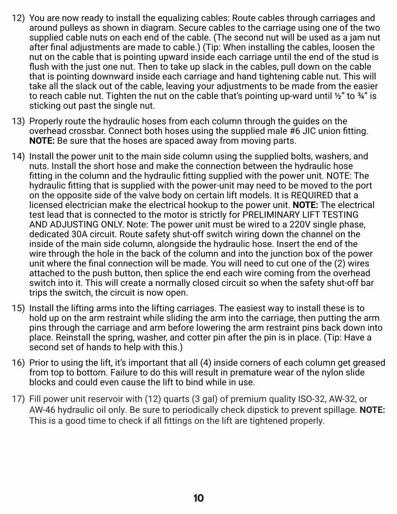
12) You are now ready to install the equalizing cables: Route cables through carriages and around pulleys as shown in diagram. Secure cables to the carriage using one of the two supplied cable nuts on each end of the cable. (The second nut will be used as a jam nut after final adjustments are made to cable.) (Tip: When installing the cables, loosen the nut on the cable that is pointing upward inside each carriage until the end of the stud is flush with the just one nut. Then to take up slack in the cables, pull down on the cable that is pointing downward inside each carriage and hand tightening cable nut. This will take all the slack out of the cable, leaving your adjustments to be made from the easier to reach cable nut. Tighten the nut on the cable that’s pointing up-ward until ½” to ¾” is sticking out past the single nut.
13) Properly route the hydraulic hoses from each column through the guides on the overhead crossbar. Connect both hoses using the supplied male #6 JIC union fitting. NOTE: Be sure that the hoses are spaced away from moving parts.
14) Install the power unit to the main side column using the supplied bolts, washers, and nuts. Install the short hose and make the connection between the hydraulic hose fitting in the column and the hydraulic fitting supplied with the power unit. NOTE: The hydraulic fitting that is supplied with the power-unit may need to be moved to the port on the opposite side of the valve body on certain lift models. It is REQUIRED that a licensed electrician make the electrical hookup to the power unit. NOTE: The electrical test lead that is connected to the motor is strictly for PRELIMINARY LIFT TESTING AND ADJUSTING ONLY. Note: The power unit must be wired to a 220V single phase, dedicated 30A circuit. Route safety shut-off switch wiring down the channel on the inside of the main side column, alongside the hydraulic hose. Insert the end of the wire through the hole in the back of the column and into the junction box of the power unit where the final connection will be made. You will need to cut one of the (2) wires attached to the push button, then splice the end each wire coming from the overhead switch into it. This will create a normally closed circuit so when the safety shut-off bar trips the switch, the circuit is now open.
15) Install the lifting arms into the lifting carriages. The easiest way to install these is to hold up on the arm restraint while sliding the arm into the carriage, then putting the arm pins through the carriage and arm before lowering the arm restraint pins back down into place. Reinstall the spring, washer, and cotter pin after the pin is in place. (Tip: Have a second set of hands to help with this.)
16) Prior to using the lift, it’s important that all (4) inside corners of each column get greased from top to bottom. Failure to do this will result in premature wear of the nylon slide blocks and could even cause the lift to bind while in use.
17) Fill power unit reservoir with (12) quarts (3 gal) of premium quality ISO-32, AW-32, or AW-46 hydraulic oil only. Be sure to periodically check dipstick to prevent spillage. NOTE: This is a good time to check if all fittings on the lift are tightened properly.
11
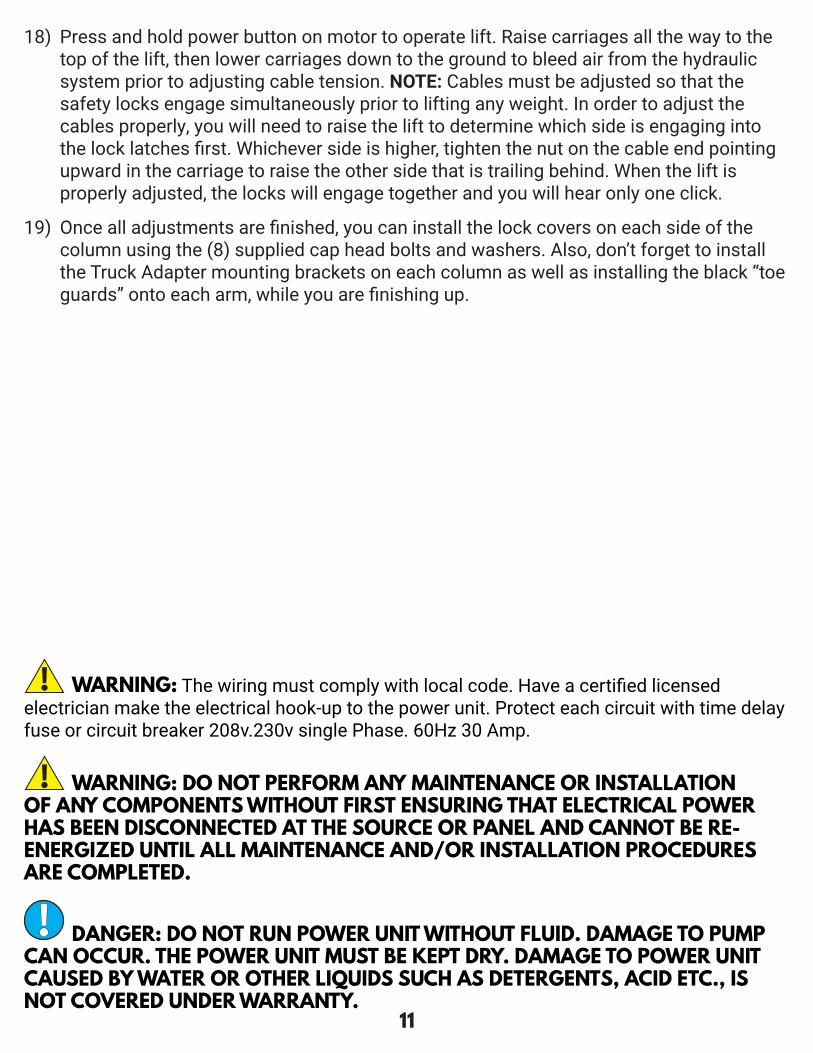
WARNING: DO NOT PERFORM ANY MAINTENANCE OR INSTALLATION OF ANY COMPONENTS WITHOUT FIRST ENSURING THAT ELECTRICAL POWER HAS BEEN DISCONNECTED AT THE SOURCE OR PANEL AND CANNOT BE RE-ENERGIZED UNTIL ALL MAINTENANCE AND/OR INSTALLATION PROCEDURES ARE COMPLETED.
DANGER: DO NOT RUN POWER UNIT WITHOUT FLUID. DAMAGE TO PUMP CAN OCCUR. THE POWER UNIT MUST BE KEPT DRY. DAMAGE TO POWER UNIT CAUSED BY WATER OR OTHER LIQUIDS SUCH AS DETERGENTS, ACID ETC., IS NOT COVERED UNDER WARRANTY.
WARNING: The wiring must comply with local code. Have a certified licensed electrician make the electrical hook-up to the power unit. Protect each circuit with time delay fuse or circuit breaker 208v.230v single Phase. 60Hz 30 Amp.
18) Press and hold power button on motor to operate lift. Raise carriages all the way to the top of the lift, then lower carriages down to the ground to bleed air from the hydraulic system prior to adjusting cable tension. NOTE: Cables must be adjusted so that the safety locks engage simultaneously prior to lifting any weight. In order to adjust the cables properly, you will need to raise the lift to determine which side is engaging into the lock latches first. Whichever side is higher, tighten the nut on the cable end pointing upward in the carriage to raise the other side that is trailing behind. When the lift is properly adjusted, the locks will engage together and you will hear only one click.
19) Once all adjustments are finished, you can install the lock covers on each side of the column using the (8) supplied cap head bolts and washers. Also, don’t forget to install the Truck Adapter mounting brackets on each column as well as installing the black “toe guards” onto each arm, while you are finishing up.

12
7-OPERATION INSTRUCTIONS WARNING: LIFT OPERATION BY TRAINED AUTHORIZED PERSONNEL OVER 18 YEARS ONLY. APPLY THE PARKING BRAKE AFTER POSITIONING THE VEHICLE ON THE LIFT. DO NOT ALLOW ANYONE TO STAY IN LIFT AREA DURING RAISING AND LOWERING CYCLES. CLOSELY WATCH THE VEHICLE AND THE LIFT DURING RAISING AND LOWERING CYCLES. OBSERVE THE RATED LOAD CAPACITY AND LOAD DISTRIBUTION. DO NOT ALLOW ANYONE TO CLIMB ON LIFT OR STAY INSIDE VEHICLE. AFTER RAISING THE VEHICLE FRAME 6”, STOP AND CHECK ADAPTERS FOR SECURE CONTACT. PERFORM BUMPER TEST(PG.2). MAKE SURE THE VEHICLE DOORS ARE CLOSED DURING RAISING AND LOWERING CYCLES.
WARNING: IN CASE OF DEFECTS OR MALFUNCTIONS SUCH AS JERKY LIFT MOVEMENT OR DEFORMATION OF THE SUPERSTRUCTURE, SUPPORT OR LOWER THE LIFT IMMEDIATELY. CONTACT QUALIFIED SERVICE PERSONNEL.
WARNING: PAY CLOSE ATTENTION WHEN SETTING THE LOCKS. THE LOCKS MUST BE A LEVEL MATCH SET IN ORDER TO AVOID A VEHICLE TILT.
WARNING: ALWAYS LOCK THE LIFT BEFORE GOING UNDER THE VEHICLE. NEVER ALLOW ANYONE TO GO UNDER THE LIFT WHEN RAISING OR LOWERING.
7.1 DEFECTS / MALFUNCTIONS
7.2 CONTROLS
7.2.1 UP CONTROL
7.2.2 SAFETY LOCK CONTROL
The safety latch mechanism will “Trip Over” as the lift raises and drop into each safety latch stop. To lock the lift you must press the lowering handle on the power unit (Fig. 1) to relieve the hydraulic pressure and let the safety locks engage into a level locked position.
Once the up button is actuated, the lift moves up until the button is released or the limit stop is reached.
UP

13
1. Before driving a vehicle onto the lift make sure the lift is fully lowered. Before driving a vehicle onto the lift, position the lift arms outward. Do not hit or run over the lifting arms, as this could damage the vehicle and/or lift. Make sure the lift is fully lowered before moving the vehicle over the lift. NOTE: It is recommended to swing both arms outward pointing toward the front of the lift prior to loading a vehicle into the HD2P-13KCL.
2. Drive the vehicle over the lift while keeping the vehicle parallel with the lift and aligning the center of gravity of the vehicle with the center of the lift. NOTE: The “Center of Gravity” (COG) of the vehicle is the balance point at which there is equal weight in front of and behind the COG, and equal weight on both sides of the COG. The COG is not necessarily the dimensional center of the vehicle, but is often slightly toward the engine from the dimensional center of the vehicle.
3. Turn off the vehicle’s engine and engage the parking brake of the vehicle.4. Read the vehicles owner’s manual to identify the recommended vehicle lifting points.5. Prepare the work area according to this manual. Move the lifting arms inward, and
position the rubber pads to contact with the vehicle manufacturer’s recommended lifting points.
7.3 OPERATION
NOTE: IT IS NORMAL FOR AN EMPTY LIFT TO LOWER SLOWLY - IT MAY BE NECESSARY TO ADD WEIGHT.
7.2.3 LOWERING CONTROL
WARNING: FAILURE TO OPERATE THE LIFT ACCORDING TO THIS MANUAL MAY CAUSE DAMAGE TO THE LIFT, PROPERTY DAMAGE AND/OR PERSONAL INJURY.
IMPORTANT: PLACE THE FOUR RUBBER PADS UNDER EDGE OF VEHICLE AT THE FOUR JACK POINTS.
6. Once the lifting arms have been positioned under the vehicle lifting points, operate the power switch to make contact and lift the vehicle slightly. Test to make sure the vehicle is well balanced and the contact between the rubber pads and vehicle lifting points are secure by performing the “BUMPER TEST.” (pg. 2) Then proceed to lift the vehicle to the desired height.
Press the up button enough to allow the safety locks to be disengaged. Pull the latch release handle (Fig. 1) to release the safety locks.
WARNING: ALWAYS ENSURE BOTH SIDES RELEASE.Press the lowering handle (Pg. 17 Fig. 2) until the lift is completely lowered. Fig. 1

14
7. WARNING: Do not lift the vehicle if you cannot establish secure and level lifting points. Do not use sub-standard shims or other devices in place of approved and recommended rubber pad adapters. Never use the lift without the rubber pads in place on each plate and in contact with the lifting points of a vehicle.
8. Press up button and raise vehicle to desired height. Do not go under vehicle until load rests on level safety locks.
9. While lifting the vehicle a clicking sound should be noticeable which indicates the safety mechanism is operating. If this sound is not heard, immediately cease using the lift and call an authorized service agent.
10. When lift reaches maximum height, a limit switch will come into operation and stop the lift. When lift has stopped, press and hold the lowering handle (Fig. 1) until load rests on level safety locks.
11. Once the repair work to the vehicle is complete, make sure to remove all tools, safety jack stands, and materials from under the vehicle and lift. Also, make sure the work area is clear and it is safe to lower the vehicle.
12. Lower vehicle by pressing the Up button to disengage the safety locks. Pull the latch release to release (Fig. 2) the safety locks then press the lowering handle (Fig. 1) until the lift is completely lowered.
13. Move the lifting arms outward, out of the path of the vehicle. Clear all bystanders, and any objects from work area and direction of vehicle.
14. Disengage the vehicle parking brake. Start the vehicle’s engine, and drive the vehicle off the lift slowly and carefully.
WARNING: THE OPERATOR MUST BE TRAINED AND AUTHORIZED TO OPERATE THE LIFT.
WARNING: DO NOT GO UNDER VEHICLE UNDER ANY CIRCUMSTANCES WHILE VEHICLE IS BEING RAISED OR LOWERED.
WARNING: LOAD MUST BE EVENLY DISTRIBUTED BETWEEN BOTH LIFTING PLATFORMS. IF LOAD IS UNBALANCED, REPOSITION VEHICLE. DO NOT LOWER ON TO LOCKS AT DIFFERENT HEIGHTS.

15
8-MAINTENANCE WARNING: DISCONNECT THE POWER BEFORE SERVICING THE LIFT.
IMPORTANT: THE MAINTENANCE INTERVALS INDICATED BELOW APPLY TO AVERAGE WORKSHOP USE. THE LIFT SHOULD BE INSPECTED MORE FREQUENTLY FOR SEVERE USE APPLICATIONS.
It is important to keep the lift clean, dry, lubricated and well maintained by establishing a periodic preventive maintenance program to ensure trouble-free operation and long service life.
1. Check safety locking mechanism is functioning correctly.2. Check safety lock audibly and visually while in operation.3. Check safety latches for free movement and full engagement with rack.4. Inspect the condition of rubber lifting pads and replace as necessary if worn or torn.5. Check hydraulic connections, and hoses for leakage.6. Check chain connections - Bends, cracks - and looseness.7. Check for frayed cables in both raised and lowered positions.8. Check snap rings at all rollers and sheaves.9. Check bolts, nuts, and screws and tighten.10. Check wiring & switches for damage.11. Keep base plate free of dirt, grease or any other corrosive substances.12. Check floor for stress cracks near anchor bolts.13. Check swing arm restraints.
1. Check anchor bolts torque to 85 ft-lbs for the 3/4’’ anchor bolts. NOTE: DO NOT USE IMPACT WRENCH.
2. Check floor for stress cracks near anchor bolts.3. Check hydraulic oil level.4. Check and tighten bolts and nuts, and screws.5. Check cylinder pulley assembly for free movement or excessive wear on cylinder yoke or
pulley pin.6. Check cable pulley for free movement and excessive wear.
8.1 MAINTENANCE SCHEDULE
8.1.1 DAILY
8.1.2 WEEKLY

16
8.1.3 MONTHLY
8.1.4 BI-MONTHLY
8.1.5 YEARLY
8.1.6 EVERY OTHER YEAR
1. Check safety mechanism operation.2. Check condition of shafts, shaft locks and bushings.3. Check overall cleanliness.
1. Check condition of extensions and lubricate.2. Check oil leaks from cylinders.3. Check oil leaks at pipe joints.
Service and safety inspection on the lift must be performed by a competent person. This inspection must be recorded. If the 12 month service and safety inspection is not performed, the warranty is null and void.
1. Lubricate chain.2. Grease the inside corners of the columns.3. Change the hydraulic fluid. A good maintenance program makes it mandatory to keep
hydraulic fluid clean. Operating temperature, type of service, contamination levels, filtration, and chemical composition of fluid should be considered. If operating in harsh or dusty conditions, a shorter interval may be required.
THE FOLLOWING ITEMS SHOULD ONLY BE PERFORMED BY A TRAINED MAINTENANCE EXPERT.• Replace hydraulic hoses.• Replace chains and rollers.• Replace cables and sheaves.• Replace or rebuild air and hydraulic cylinders as required.• Replace or rebuild pumps / motors as required.• Check hydraulic and air cylinder rod and rod end (threads) for deformation or damage.• Check cylinder mount for looseness and damage.
Relocating or changing components may cause problems. Each component in the system must be compatible; an undersized or restricted line will cause a drop in pressure. All valve, pump, and hose connections should be sealed and/or capped until just prior to use. Air hoses can be used to clean fittings and other components. However, the air supply must be filtered and dry to prevent contamination. Most important - CLEANLINESS - contamination is the most frequent cause of malfunction or failure of hydraulic equipment.
Hydraulic oil should be replaced.

17
8.2 MAINTENANCE BY OPERATOR
8.2.1 HYDRAULIC SYSTEM
8.2.2 GREASING POINTS
All moving parts have been lubricated at the factory and should be re-lubricated before the first use and at least once every six months to prevent damage.
IMPORTANT: AFTER CLEANING WORKSHOP FLOOR OR LIFT, TO MAINTAIN HOIST EFFICIENCY WE ADVISE TO LUBRICATE LIFTING ARM LOCKING MECHANISM, AND SAFETY LOCKING MECHANISM. CHECK SAFETY LOCKING MECHANISM IS FUNCTIONING CORRECTLY.
FIG. 2
SLIDE TRACKS:• The carriage assembly slide tracks should be greased every six months (or more
frequently in case of noise generation).• Slightly grease the slide tracks over their whole length using a brush.
ARM PINS:• Grease the arm pins to prevent excessive wear
1. Check the fluid level with the lift fully lowered and add fluid as required. Use premium quality ISO-32, AW-32, or AW-46 hydraulic oil.
2. Visually check all hydraulic hoses and connections for tightness before each use to ensure proper working condition.
3. Lightly oil the cylinder rods at least once every six months or when they become dry.

18
8.2.3 OPERATION AND WEAR CHECKS
8.2.4 LIFT STABILITY
8.3 CLEANING
1. Examine lift for structural cracks, bends, or other signs of damage prior to each use. Do not use this product if worn or damaged.
2. Check that the safety locking mechanism is functioning correctly.3. Check that the safety lock is audibly and visibly operating correctly.4. Check the floor for stress cracks near the anchor bolts.
1. Every six months check the nuts of all bolts for correct installation torque.2. Retighten them as required. NOTE: DO NOT USE AN IMPACT WRENCH.
DANGER: DO NOT USE HIGH PRESSURE / STEAM JET CLEANERS OR CAUSTIC CLEANING AGENTS.
1. Periodically wash off aggressive substances and treat the lift with oil or wax spray.2. Repair the damage to the paintwork immediately to prevent corrosion.

19
9-TROUBLESHOOTING1� Motor does not run:
A. Breaker or fuse blown.B. Motor thermal overload tripped. Wait for overload to cool.C. Faulty wiring connections……Call electrician for service.D. Defective up button……Call electrician for service.
2� Motor runs but will not raise:A. A piece of trash is under the check valve. Push handle down and push the up button
at the same time. Hold for 10-15 seconds. This should flush the system.B. Check the clearance between the plunger valve of the lowering handle. There should
be 1/16”.C. Remove the check valve cover and clean ball and seat.D. Oil level too low. Oil level should be just under the vent cap port when the lift is in the
lowered position. 3� Oil blows out breather of power unit:
A. Oil reservoir overfilled.B. Lift lowered too quickly while under a heavy load.
4� Motor hums and will not run:A. Impeller fan cover is dented. Take off and straighten.B. Faulty wiring……Call electrician.C. Bad capacitor……Call electrician.D. Low voltage……Call electrician.E. Lift overloaded……Reduce weight.
5� Lift jerks going up and down: Air in hydraulic system� Raise lift all the way to top and return to floor; Repeat 4-6 times. Do not let this overheat power unit.
6� Oil leaks:A. Check the power unit: If the power unit leaks hydraulic oil around the tank-mounting
flange, check the oil level in the tank. The level should be two inches below the flange of the tank. Check with a screwdriver.
B. Check the rod end of the cylinder: If the rod seal of the cylinder is out, rebuild or replace the cylinder.
C. Breather end of the cylinder: If the piston seal of the cylinder is out, rebuild or replace the cylinder.
7� Lift makes excessive noise:A. Column of the lift is dry and requires grease.B. Cylinder pulley assembly or cable pulley assembly is not moving freely.C. May have excessive wear on pins or cylinder yoke.

20
10-OWNER/EMPLOYER RESPONSIBILITIESThe owner/employer:Shall establish procedures to periodically maintain, inspect and care for the lift in accordance with the manufactures recommended procedures to ensure it’s continued safe operations.
Shall provide necessary lockout / tag outs of energy sources per ANSI Z244.1 - 1982 before beginning any lift repairs. Shall not modify the lift in any manner without prior written consent of the manufacturer.
Shall display this manual or copy supplied with the lift in a conspicuous, dry location in the lift area convenient to the operator.
Shall insure that lift operators are instructed in the safe proper use and operation of the lift using the manufacturer’s instructions outlined within this manual supplied with the lift.

21
FIG. 1 - HD2P-13KCL
117.50”
142.75”
151.00”
4” - 72.75”
32” - 45.50”
11-DIAGRAMS (FIG. 1-8)

22
FIG. 2 - HD2P-13KCLColumn
Anchor Bolts3/4” * 6.25”
Column
6”
Concrete 3000PSI min
Torque Nut
23
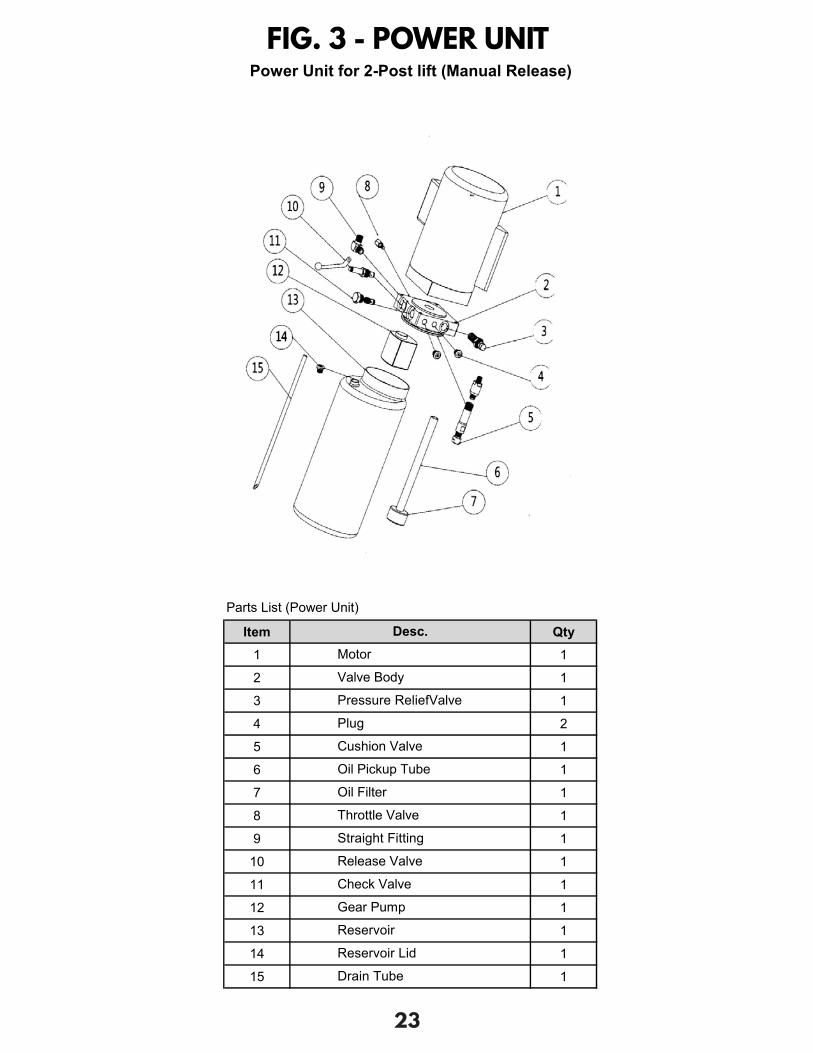
FIG. 3 - POWER UNIT
Parts List (Power Unit)
Item Qty1 1
2 1
3 1
4 2
5 1
6 1
7 1
8 1
9 1
10 1
11 1
12 1
13 1
14 1
15 1
Gear Pump
Reservoir
Reservoir Lid
Drain Tube
Power Unit for 2-Post lift (Manual Release)
Oil Pickup Tube
Oil Filter
Throttle Valve
Straight Fitting
Release Valve
Check Valve
Desc.Motor
Valve Body
Pressure ReliefValve
Plug
Cushion Valve

24
FIG. 4 - MAIN COLUMN
AB
C
1
234 56
7
7 89
9
10
11
14151617
1819
20
14
14
14 1412
4 4
212223
1414
13
26
25
A
1414
141426
25
31
B
27 27
27 2728
28
28
28
28
28
28
28
29
29
29
29
30
30
30
30
C
2727
2728 28 28 2728
29 28 28 2828
29 29
30 29
30 30
30

25
FIG. 5 - OFFSIDE COLUMN
BA
1A
23456
7
7
8
9
9
11
20
1719 18
161514
14
1414
1432
141425
26
414
1433
26
424
B
27 27
27 2728 28
2828 28 28
2853
29
29 29
29
30
3030
30
A
141431
1414
2526

26
FIG. 6 - CARRIAGE
A
A
4343
4343 43 29 29 54
2943 29 29 54
3535
3636
3837
37
39A
38A
4040
4040
39B
39
79
89
741
41
45
5042505152
45
41 41 5246
4949
4848
42 42
4251
4747
45
34
45
29
B
B

27
A
BC
536
66
65
5
56
57
5556
58
55
5959
59
359
33
3 2
2
22
60 1561
16
A62 62
62
626363
6364
64
6464
63
6565
6565B
6060
1515
1616
6161
C60
6015
1516
16 6161
FIG. 7 - CROSSBEAM
28
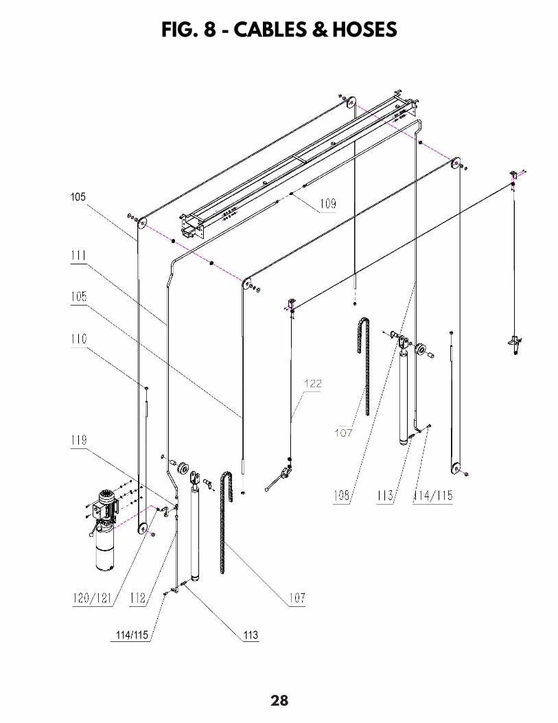
FIG. 8 - CABLES & HOSES

29
ITEM DESCRIPTION QTY ITEM DESCRIPTION QTY1 Main column assembly 1 34 Carriage assembly 2
1A Offside column assembly 1 35 Lifting pad assembly 42 Hex bolt - M8x8 2 36 Rubber lifting pad 43 Washer - Ø8 2 37 Clip - C50 44 Spring washer - C25 6 38 Forearm of 2-stage straight arm assembly 25 Copper bush - Ø29x25x16 2 38A Rear arm of 2-stage straight arm assembly 26 Wire rope pulley 2 39 Forearm of 3-stage straight arm assembly 27 Flat washer - M8 6 39A Middle section of 3-stage straight arm assembly 28 Pin of chain - Ø7.7x55 3 39B Rear arm of 3-stage straight arm assembly 29 Pin - Ø3.2 6 40 Hex bolt - M8x12 8
10 Power unit - YS79L-2F 1 41 Slide block 2 811 Oil cylinder - LY1610YK 2 42 Pin-shaft of lifting arm 812 Lock cover (mainside) 1 43 Hex bolt - M10x16 1213 Hex bolt - M5x12 1 44 Spring washer - M10 414 Hex bolt - M6x12 27 45 Slide block 1 815 Spring washer - M6 2 46 Crashproof block 416 Flat washer - M6 2 47 Hex bolt - M8x20 817 Shaft assembly of chain 2 48 Spring washer - M8 818 Copper bush - Ø34x30x50 2 49 Lock washer - M8 819 Chain wheel 2 50 Lock system of lifting arm 420 Spring washer - C30 2 51 Pressure spring - Ø31x3.2x165 421 Lock release handle 1 52 Lock bar of lifting arm 422 Shaft of safety lock 1 53 Crossbeam assembly 123 Lock teeth assembly (Left) 1 54 Arm Restraint Gear 224 Lock teeth assembly (Right) 1 55 Limit switch pipe 125 Lock release wire pulley 3 56 Connecting board 226 Shaft of lock release 6 57 Sponge tube - Ø30x5x1800 127 Outside hex bolt - M10x40 12 58 Limit switch - LX19-001 128 Flat washer - M10 8 59 Clip - C25 429 Spring washer - M10 4 60 Nut - M6 530 Nut - M10 4 61 Hex bolt - M6x16 531 Trundle bracket 2 62 Nut - M4 432 Lock cover (offside) 1 63 Spring washer - M4 433 Pull spring - 84xØ1.6 1 64 Flat washer - M4 434 Carriage assembly 1 65 Hex bolt - M4x20 435 Lifting pad assembly 236 Rubber lifting pad 2
PARTS LIST

30
ITEM DESCRIPTION QTY105 Cable 10900mm 2107 Chain 1108 Hydraulic Hose 5300mm 1109 Hydraulic Hose Fitting 9/16 to 9/16 1110 Nut for cable M16 1111 Hydraulic Hose 4450mm 1112 Hydraulic Hose 940mm 1113 Connector to Cylinder 65mm 2114 Banjo Bolt 2115 Combination Seal 2119 T-Fitting 1120 Hydraulic Hose 430mm 1121 Connector to Power Unit 1/4 to 3/8 1122 Safety Release Cable 1

31
NOTES

32
P.O. Box 7069 • Greenwood, IN 46142 • Ph. 888-908-4826 • Fx. 317-215-2770 • www.titanlifts.com
LIMITED WARRANTYThe Titan 2 Post lifts, 4 Post lifts and Bridge Jacks are backed by a standard 1-year replacement parts warranty and a 5-year structural warranty from the date of purchase, to the original purchaser only. The 1-year replacement parts warranty covers power units, hydraulic cylinders, and all other assembly components such as, but not limited to: turn plates, slip plates, cables, chains, valves, switches etc. This does not cover normal wear items such as, but not limited to: rubber lifting pads and nylon slide blocks. Titan Elite model lifts have been discontinued but still qualify under the same terms as shown above.
Titan SL-6600 Scissor Lifts and PREMIER Series 2 Post Lifts are backed by a 2-year replacement parts warranty and a 5-year structural warranty from the date of purchase, to the original purchaser only. The 2-year replacement parts warranty covers power units, hydraulic cylinders, and all other assembly components such as, but not limited to: valves, switches, capacitors etc. This does not cover normal wear items such as, but not limited to: rubber lifting pads, nylon slide blocks and rubber arm pads.
Titan MRL-6000 Scissor lifts are backed by a standard 1-year replacement parts warranty and a 5-year structural warranty from the date of purchase, to the original purchaser only. The 1-year replacement parts warranty covers power units, hydraulic cylinders, and all other assembly components such as, but not limited to: valves, switches, capacitors etc. This does not cover normal wear items such as but not limited to rubber lifting pads.
Titan ROT-4500 Rotisseries are backed by a standard 1-year replacement parts warranty from the date of purchase, to the original purchaser only. The 1-year replacement parts warranty covers components such as, but not limited to: hydraulic cylinders, caster assemblies, bearings etc. This does not cover normal wear items such as, but not limited to, mounting adapters.
Titan Standard Duty and Heavy Duty motorcycle lifts are backed by a standard 1-year replacement parts warranty from the date of purchase, to the original purchaser only. The 1-year replacement parts warranty covers power units, hydraulic cylinders, pneumatic cylinders, and all other assembly components such as, but not limited to: cables, caster wheels, valves, switches, wheel vises etc. This does not cover normal wear items such as, but not limited to: rubber wheel vise pads.
Titan Light Duty motorcycle lifts are warrantied for replacement parts only to the original purchaser for a period of 90 days from the date of purchase. This 90 day replacement parts warranty covers items such as, but not limited to: hydraulic cylinder, casters, pedal assemblies, wheel vises etc. This does not cover normal wear items such as, but not limited to: rubber wheel vise pads.
Titan Bulldog Moto Cradle Wheel Chock is warrantied for replacement parts, only to the original purchaser, for a period of 2-years from the date of purchase.
XL Tool by Titan Wheel Service Machines and Helper Arm Assemblies are backed by a standard 1-year replacement parts warranty from the date of purchase, to the original purchaser only. The 1-year replacement parts warranty covers internal boards, motors, pneumatic cylinders, and all other assembly components such as, but not limited to: cabinet, switches, valves, fittings etc. This does not cover normal wear items such as but not limited to: rubber pads, jaw protectors, air hoses, quick nut assemblies.
Titan shop equipment products and accessories are warrantied for replacement parts only to the original purchaser for a period of 90 days from the date of purchase. This 90 day replacement parts warranty covers products such as but not limited to: EZ -Mover Jacks, Mini Jacks, tie down products, wheel service accessories, Bulldog Moto Cradle Wheel Chock accessories, dollies, stands, Multi-purpose Jacks, etc.
Titan TJ1T, FJ2T, and FJ3T are warrantied for replacement parts only to the original purchaser for a period of 1 year from the date of purchase.
All non-serialized items will require proof of purchase in the form of a sales receipt from an authorized Titan Lifts dealer showing the date of purchase for any warranty consideration.
For all warranty considerations, Titan Marketing, LLC will supply replacement parts only during the warranty period. The original purchaser is responsible for all shipping, handling, and any labor charges incurred. Hydraulic/Pneumatic cylinders may qualify for exchange under warranty if reported within the first 30 days from date of sale. After the first 30 days from date of sale, a seal kit and installation instructions will be sent for cylinder repairs. All defective parts must be returned to Titan for inspection and examination. Any parts that are found to be defective will be replaced or repaired to proper working order. Other items not listed above may be considered general wear parts and therefore, will not be covered under warranty. These warranties do not extend to defects caused by ordinary wear, abuse, misuse, shipping damage, improper installation, voltage or lack of required maintenance. Titan Marketing, LLC is not to be held responsible for any failure that results from an accident, purchaser/operator abuse, neglect, or failure to operate products in accordance with instructions provided in the owner’s manual(s) supplied. Damage caused by rain, excessive humidity, corrosive environments or other contaminants are not covered under warranty. THESE WARRANTIES DO NOT EXTEND TO ANY COSMETIC DEFECT NOT INTERFERING WITH EQUIPMENT FUNCTIONALITY OR ANY INCIDENTAL, INDIRECT, OR CONSEQUENTIAL LOSS, DAMAGE, OR EXPENSE THAT MAY RESULT FROM ANY DEFECT, FAILURE OR MALFUNCTION OF A TITAN MARKETING LLC PRODUCT OR THE BREACH OR DELAY IN PERFORMANCE OF THE WARRANTY.
33
EQUIPMENT MODEL:
TYPE OF POWER UNIT:
DATE OF PURCHASE:
PLACE PURCHASED:
NAME:
STREET:
CITY, STATE, ZIP:
PHONE:
EMAIL:
SERIAL NUMBER:
SERIAL NUMBER:
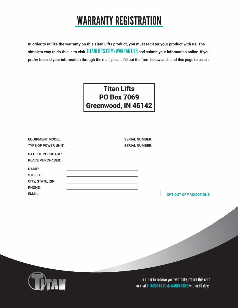
WARRANTY REGISTRATION
OPT OUT OF PROMOTIONS
In order to utilize the warranty on this Titan Lifts product, you must register your product with us. The
simplest way to do this is to visit TITANLIFTS.COM/WARRANTIES and submit your information online. If you
prefer to send your information through the mail, please fill out the form below and send this page to us at :
Titan LiftsPO Box 7069
Greenwood, IN 46142
In order to receive your warranty, return this card or visit TITANLIFTS.COM/WARRANTIES within 30 days.


NOTES

WARNINGThe warnings, precautions and instructions in this manual cannot cover all possible conditions and situations that may occur. The operator must understand that the operator must supply common sense and examine caution factors when using this product to determine safety in all circumstances being used.
PO Box 7069 Greenwood, IN 461421.888.908-4826 FAX (317) 215.2770
www.titanlifts.com
TITAN MARKETING, LLC
Copyright © 2020 by Titan Marketing, LLC. All rights reserved. No portion of this manual or any artwork contained herein may be reproduced in any shape or form without the express consent of Titan Marketing, LLC. Diagrams within this manual may not be drawn proportionally. Due to continuing improvements, actual product may differ slightly from the product described herein. Tools required for assembly and service may not be included.
Patent No.: US 8,104,588 B2 CA 2,729,670 4/7/20