Embed Size (px)
Citation preview
All information contained herein is subject to change without notice.
Goodman Manufacturing Company, L.P.I0-213D 2550 North Loop West, Suite 400, Houston, TX 77092 2/04
www.goodmanmfg.com© 2003-2004 Goodman Manufacturing Company, L.P.
WARNINGDO NOT USE THIS FURNACE IF ANY PART HASBEEN UNDER WATER. IMMEDIATELY CALL AQUALIFIED SERVICE TECHNICIAN TO INSPECTTHE FURNACE AND TO REPLACE ANY PART OFTHE CONTROL SYSTEM AND ANY GAS CONTROLTHAT HAS BEEN UNDER WATER.
WARNINGTHIS FURNACE IS DESIGN CERTIFIED FORINSTALLATION IN BUILDINGS CONSTRUCTED ONSITE ONLY.
C US
®
INSTALLATION & OPERATINGINSTRUCTIONS
for GMNTCONDENSING GAS FURNACE
(CATEGORY IV)
amaEFFICIENCYRATINGCERTIFIED
WARNINGIF THIS FURNACE IS INSTALLED IN AN ENCLOSEDAREA, SUCH AS A GARAGE OR UTILITY ROOM,EITHER ALONE OR WITH ANY OTHER CARBONMONOXIDE PRODUCING DEVICE (E.G.AUTOMOBILE, SPACE HEATER, WATER HEATER,ETC.), ENSURE THAT THE ENCLOSED AREA ISPROPERLY VENTILATED.
WARNINGCARBON MONOXIDE (REFERRED TO AS CO) CANCAUSE SERIOUS PERSONAL INJURY OR DEATH.
IO-213D 2/042
INDEXREPLACEMENT PARTS................................................ 2WARNINGS ................................................................... 2GENERAL INFORMATION ............................................. 3LOCATION, CLEARANCES ........................................... 4COMBUSTION AIR ........................................................ 4VENTING ....................................................................... 5CONDENSATE DRAINS ................................................ 8GAS PIPING ................................................................ 11CIRCULATING AIR ....................................................... 11ELECTRICAL SUPPLY CONNECTIONS ...................... 12CONTROL VOLTAGE CONNECTIONS ........................ 12FEATURES .................................................................. 12RATING THE FURNACE .............................................. 13TIMING THE GAS METER ........................................... 13
SPECIAL INSTRUCTIONS FOR WHITE....................... 14RODGERS 36G22 GAS VALVE ADJUSTMENTSAFETY CONTROL ..................................................... 15CIRCULATING AIR FILTERS ........................................ 16TEMPERATURE RISE ................................................. 16MOTOR LUBRICATION AND MAINTENANCE .............. 16SERVICE INSTRUCTIONS........................................... 16SEQUENCE OF OPERATION...................................... 16REMOVING AN EXISTING APPLIANCE....................... 17INSPECTING AND CLEANING ..................................... 17THE HEAT EXCHANGERLIGHTING INSTRUCTIONS .......................................... 18WIRING DIAGRAM ...................................................... 19
THIS FURNACE CONTAINS ELECTRONIC COMPONENTS,WHICH REQUIRE A DEFINITE GROUND. PROVISIONS AREMADE FOR CONNECTION OF THE GROUND. A DEDICATEDGROUND FROM THE MAIN POWER SUPPLY OR AN EARTHGROUND MUST BE PROVIDED.
REPLACEMENT PARTSReplacement parts for this appliance are available throughyour contractor or local distributor. For the location of yournearest distributor consult the white business pages, theyellow page section of the local telephone book or contact:
SERVICE PARTS DEPARTMENTGOODMAN MANUFACTURING CO., L.P.2550 NORTH LOOP WEST, SUITE 400
HOUSTON, TEXAS 77092(713) 861 � 2500
The major parts groups are as follows:
BLOWER ASSEMBLYMotorBlower HousingBlower wheelMisc. sheetmetal itemsCapacitor
HEAT EXCHANGERHeat exchanger sectionsSecondary coilCollector Box
ELECTRICAL CONTROLSControl boardAuxiliary / main limit switchRoll-out switchTransformerDoor interlock switchAir pressure switchInduced draft blower
BURNER ASSEMBLYBurnersManifoldOrificesGas ValveIgniterFlame sensor
MISCELLANEOUSWrapperAccess doorsChimneyGaskets and sealsWiring assemblies
In order to effectively process the parts requirement thedistributor / contractor will need the entire model numberand serial number found on the series and rating platelocated inside the blower compartment.
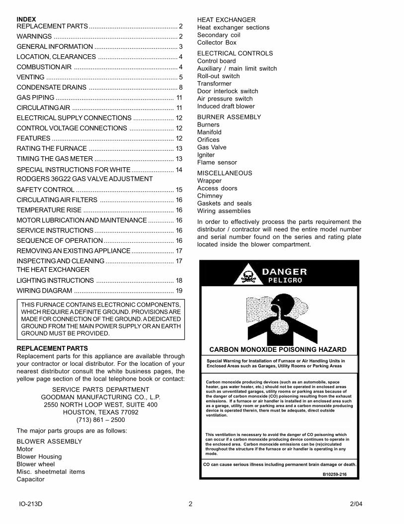
CARBON MONOXIDE POISONING HAZARD
-
Special Warning for Installation of Furnace or Air Handling Units inEnclosed Areas such as Garages, Utility Rooms or Parking Areas
Carbon monoxide producing devices (such as an automobile, spaceheater, gas water heater, etc.) should not be operated in enclosed areassuch as unventilated garages, utility rooms or parking areas because ofthe danger of carbon monoxide (CO) poisoning resulting from the exhaustemissions. If a furnace or air handler is installed in an enclosed area suchas a garage, utility room or parking area and a carbon monoxide producingdevice is operated therein, there must be adequate, direct outsideventilation.
This ventilation is necessary to avoid the danger of CO poisoning whichcan occur if a carbon monoxide producing device continues to operate inthe enclosed area. Carbon monoxide emissions can be (re)circulatedthroughout the structure if the furnace or air handler is operating in anymode.
CO can cause serious illness including permanent brain damage or death.
B10259-216
IO-213D 2/043
WARNINGWHILE CARBON MONOXIDE DETECTORS DO PROVIDEADDITIONAL PROTECTION, LIMITATIONS TO THEIREFFECTIVENESS REQUIRE THAT YOU OTHERWISECONTINUE TO FOLLOW APPROPRIATE INSTRUCTIONSLOCATED IN THE �INSTALLATION & OPERATINGINSTRUCTIONS� AND �USER�S INFORMATION MANUAL�RELATING TO PROTECTING PERSONS FROM THE RISKSOF CARBON MONOXIDE. REVIEW EACH CO DETECTOR�SMANUFACTURERS� EXPLANATION OF THEIR UNIT�SCAPABILITIES AND FOLLOW THE INSTALLATION ANDOPERATING MANUAL WHEN INSTALLING ANDOPERATING SUCH UNITS.
WARNINGTHE CIRCULATING AIR DUCTS MUST BE COMPLETELYAND POSITIVELY SEALED TO PREVENT THECOMBUSTION PRODUCTS, INCLUDING CARBONMONOXIDE, FROM ENTERING THE LIVING SPACE.
WARNINGTO ENSURE PROPER INSTALLATION AND OPERATION OFTHIS PRODUCT, COMPLETELY READ AND UNDERSTANDTHESE INSTRUCTIONS PRIOR TO ATTEMPTING TOASSEMBLE, INSTALL, MAINTAIN, OR REPAIR. IF THESEINSTRUCTIONS ARE NOT FOLLOWED PRECISELY THEREIS A POTENTIAL OF CARBON MONOXIDE POISONING,WHICH CAN RESULT IN SERIOUS ILLNESS OR DEATH.
WARNINGUNLESS ALLOWED BY LOCAL CODE, DO NOT INSTALL ALIQUID PETROLEUM GAS BURNING APPLIANCE IN A PIT,BASEMENT, OR SIMILAR LOCATION. L.P., A HEAVIER THANAIR GAS, CAN COLLECT IN LOW AREAS AND MAY NOTDISPERSE NATURALLY. APPLIANCES SO FUELED SHALLNOT BE INSTALLED IN AN ABOVE GRADE UNDER FLOORSPACE OR BASEMENT UNLESS SUCH LOCATION ISPROVIDED WITH APPROVED MEANS FOR REMOVAL OFUNBURNED GAS.
WARNINGTHIS FURNACE WAS EQUIPPED AT THE FACTORY FORUSE WITH NATURAL GAS ONLY. LIQUID PETROLEUM (L.P.)CONVERSION, IF REQUIRED, MUST BE PERFORMED BYA QUALIFIED TECHNICIAN FAMILIAR WITH PERFORMINGTHIS TYPE OF CONVERSION. IF L.P. CONVERSION ISREQUIRED, ALL INSTRUCTIONS INCLUDED WITH THEFACTORY AUTHORIZED KIT MUST BE FOLLOWED. THEONLY KIT THAT MUST BE USED FOR THIS CONVERSIONIS THE FACTORY AUTHORIZED LPT-01. FAILURE TOFOLLOW THOSE INSTRUCTIONS EXPLICITLY MAY CAUSEFIRE, EXPLOSION, PROPERTY DAMAGE, PERSONALINJURY OR DEATH.
WARNINGNEVER LAY THIS FURNACE ON ITS FRONT OR REAR.
WARNINGHEATING UNIT SHOULD NOT BE UTILIZED WITHOUTREASONABLE, ROUTINE, INSPECTION, MAINTENANCEAND SUPERVISION. IF THE BUILDING IN WHICH ANYSUCH DEVICE IS LOCATED WILL BE VACANT, CARESHOULD BE TAKEN THAT SUCH DEVICE IS ROUTINELYINSPECTED, MAINTAINED AND MONITORED. IN THEEVENT THAT THE BUILDING MAY BE EXPOSED TOFREEZING TEMPERATURES AND WILL BE VACANT, ALLWATER-BEARING PIPES SHOULD BE DRAINED, THEBUILDING SHOULD BE PROPERLY WINTERIZED, ANDTHE WATER SOURCE CLOSED. IN THE EVENT THAT THEBUILDING MAY BE EXPOSED TO FREEZINGTEMPERATURES AND WILL BE VACANT, ANY HYDRONICCOIL UNITS SHOULD BE DRAINED AS WELL AND, IN SUCHCASE, ALTERNATIVE HEAT SOURCES SHOULD BEUTILIZED.
GENERAL INFORMATIONThe GMNT series furnace can be installed as an upflow,downflow or horizontal furnace. It can also be installed as adirect vent or a non-direct vent furnace.
These Installation and Operating Instructions are intendedfor use by fully qualified installation technicians. Somelocalities require the installer/sevicer to be licensed. If indoubt, check with local authorities.
INSTALLATION: In the USA, this furnace MUST be installedin accordance with the latest edition of the ANSI Z223.1booklet entitled �National Fuel Gas Code� (NFPA 54), andthe requirements or codes of the local utility or other authorityhaving jurisdiction. In Canada, this furnace must be installedin accordance with the current CAN/CGA-B149.1 & 2 GasInstallation Codes, local plumbing or waste water codes andother applicable codes.
Additional helpful publications available from the NFPA are,NFPA 90A - Installation of Air Conditioning and VentilatingSystem and NFPA 90B - Warm Air Heating and AirConditioning System.
All venting shall be in accordance with PART 7, Venting ofEquipment, of the National Fuel Gas Code, ANSI Z223.1, orapplicable local building and/or air conditioning codes.
These publications are available from:
National Fire Protection Association, Inc.Batterymarch ParkQuincy, MA 02269
The GMNT series of furnaces meet the California NOxemission standards and California seasonal efficiencystandards. ANNUAL inspections of the furnace and its ventsystem is strongly recommended. It is the installer�sresponsibility to inform the user of this importance. Anyinstallation, alteration or repair of this equipment must notbe in violation of local code or the information contained inthis manual. This furnace shall be securely fastened in placewhen installed in the vertical position. This furnace must beinstalled in such a manner as to allow for service, inspection,repair or replacement without removing permanentconstruction. A platform is recommended to allow for service.
IO-213D 2/044
LOCATION� DO NOT install this furnace in a mobile home. This furnace
is designed only for installation in buildings constructedon site and connected to ductwork. When installed in autility room or closet, the door should be wide enough toallow the largest part of the furnace to enter, or to permitthe replacement of another appliance, such as a waterheater. This furnace is designed to be installed indoorsonly.
� DO NOT install outdoors. This furnace should be installedin such a manner so that it is protected from water. If anycomponents should become wetted or submerged underwater, replace those parts before returning the furnace tooperation.
� DO NOT use as a construction heater.� DO NOT use in an area where freezing may occur without
properly protecting the vent and drain system. The drainmay crack and leak if subjected to freezing temperatures.
� DO NOT install in a room used or designed to be used asa bedroom, bathroom or storage closet, or in any enclosedspace with access only through such a room or space.
A return air filter grille or means of inserting a filter into thereturn air duct is recommended. The opening in the ductused for filter access must be capable of being sealed airtight if located in the same pressure zone as the furnace.
The furnace and it�s individual shut-off must be disconnectedfrom the gas supply piping system during any pressuretesting of that system at test pressures in excess of 1/2psig (3.5kPa)
The furnace must be isolated from the gas supply pipingsystem by closing it�s individual manual shut-off valve duringany pressure testing of the gas supply piping system atpressures equal to or less than 1/2 psig (3.5 kPa).
CLEARANCESMIN. CLEARANCES TO COMBUSTIBLE SURFACESUnobstructed front clearance of 24" for servicing isrecommended.
RIGHT SIDE - 1" VENT - 0"REAR - 0" LEFT SIDE - 1"TOP OF PLENUM - 1" FRONT - 3"Line contact is permitted in the horizontal position.
ACCESSIBILITY CLEARANCE, WHERE GREATER,SHOULD TAKE PRECEDENCE OVER MINIMUM FIREPROTECTION CLEARANCE.
A gas-fired furnace for installation in a residential garagemust be installed so that the ignition source and burnersare located not less than eighteen inches (18") above thefloor and is protected or located to prevent physical damageby vehicles.
A gas furnace must not be installed directly on carpeting,tile, or other combustible materials other than wood flooring.
WARNINGCOMBUSTIBLE MATERIAL MUST NOT BE PLACED ON ORAGAINST THE FURNACE CABINET. THE AREA AROUNDTHE FURNACE MUST BE KEPT CLEAR AND FREE OF ALLCOMBUSTIBLE MATERIAL INCLUDING GASOLINE ANDOTHER FLAMMABLE VAPORS AND LIQUIDS. THE USERMUST BE CAUTIONED THAT THE FURNACE AREA MUSTNOT BE USED AS A BROOM CLOSET OR FOR ANY OTHERSTORAGE PURPOSE.
WARNINGA SOLID METAL BASEPLATE IS SUPPLIED WITH THISFURNACE. THIS BASEPLATE MUST BE IN PLACE ANDSEALED AIR TIGHT WHEN THE FURNACE IS INSTALLEDWITH SIDE RETURN AIR DUCTS. FAILURE TO DO SOMAY PERMIT COMBUSTION PRODUCTS, INCLUDINGCABON MONOXIDE, TO ENTER THE LIVING SPACE ANDCREATE POTENTIALLY HAZARDOUS CONDITIONS SUCHAS CARBON MONOXIDE POISONING OR DEATH. FULLSIZE RETURN AIR DUCT OPENINGS MUST BE UTILIZED.EMBOSSES ARE PROVIDED FOR THIS PURPOSE.
Before proceeding with this installation check the following:� Correct clearance from combustible materials� Adequate accessibility for servicing� Flooring is not carpet or any other combustible material,
except wood� Adequate combustion / ventilation air is supplied� Metal base plate is in place when using side(s) for return
air� In a garage, the furnace has been adequately elevated
and protected from vehicle damage� Furnace area is free of flammable materials and vapors
such as gasoline
COMBUSTION AIRThe GMNT furnace can be installed either as a Direct Vent(2 pipe) or a Non-Direct Vent (1 pipe) appliance. If installedas direct vent appliance, the combustion air is to be takenfrom the outdoors via a 2" or 3" schedule 40 PVC pipe andterminate at the furnace burner box. As a non-direct ventfurnace, the combustion air is taken from the area whichthe furnace is installed. Avoid combustion air sources thatcontain flammable fumes and vapors, and gasses such ascarbon monoxide, hydrogen sulfide, ammonia, chlorine, andhalogenated hydrocarbons.
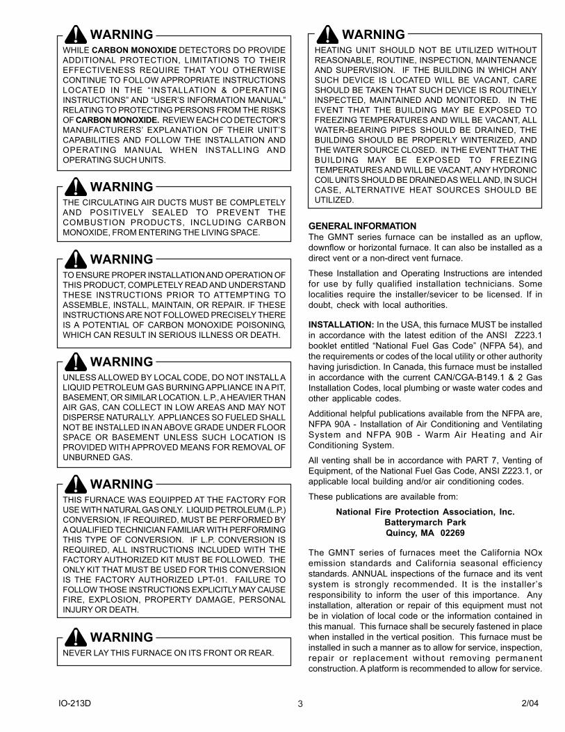
Direct Vent Combustion Air. As shown in the followingillustration, the combustion air pipe is to originate at thefurnace�s cabinet and terminate outside of the building. Thediameter of the PVC combustion air pipe depends uponthe furnace size, the length of pipe, and the quantity offittings employed. The table found in the �Combustion/VentPipe Size� section of this manual outlines these sizingrequirements. As a direct vent installation, the �Air forCombustion and Ventilation Air� requirements found in ANSIZ223.1, section 5.3 is not required for the furnace to operatecorrectly. However, other fuel burning appliances locatedin the same space as the furnace may still require that thearea be serviced with Combustion and Ventilation Airconsistent with ANSI Z223.1, section 5.3.
IO-213D 2/045
Attaching Combustion Air Intake Fitting. A coupling forattaching the combustion air fitting to the furnace cabinetis included in a plastic bag packaged with the furnace. Thefitting is sized to accept a 3" diameter PVC pipe. In certainsituation, a 2" diameter pipe can be used for this application.Refer to the combustion/ vent table for sizing requirements.Attach the fitting to the cabinet using (4) #10 x 1/2" sheetmetal screws (field supplied). If a right hand entrance ispreferred, the plug installed on this side is to be removedand reinstalled in the left side opening.
Non-Direct Vent Combustion Air. If the furnace is to beinstalled as a non-direct vent appliance, the combustion airpipe outlined previously is not used.
As a non-direct vent furnace, this must be installed inaccordance with the combustion and ventilation airrequirements found in ANSI Z221.3, section 5.3. Wheninstalled as a non-direct vent furnace in an area, which isdeemed as a confined area, see (ANSI Z223.1, section 1.7,�Space, Confined�) the requirements are as follows:
All Combustion Air Taken From The Inside Of TheBuilding. When installed as a non-direct vent furnace andindoor air is used as the combustion air source, the spaceis to be provided with (2) permanent openings communicatingdirectly with an additional room(s) of sufficient volume sothat the combined volume of all spaces meets the criteria ofan unconfined area. The total input of all gas burningequipment shall be used to determine the minimum size ofeach opening. Each opening shall be sized to be a minimumof 1 square inch of free area per 1,000 Btu/hr of combinedinput of gas utilization equipment in the area. The minimumarea for each opening shall not be less than 100 squareinches, and the minimum dimension of these openings shallnot be less than 3 inches. One opening shall commencewithin 12 inches of the top of the area, while the other openingshall commence within 12 inches of the bottom of the area.
All Combustion Air Taken From Outdoors. If installedas a non-direct furnace and outdoor air is selected as thecombustion air source, then area shall be serviced with anopening(s) communicating directly with the outdoors by eitherof the following two methods. When calculating the minimumarea for each opening, the combined input of all gas utilizationequipment is to be considered. Also, the minimumdimension for any opening shall not be less than 3 inches.
Method 1..... Two permanent openings communicatingdirectly with the outdoors via. horizontal ducts shall besized to be a minimum of 1 square inch per 4,000 Btu/hror, two permanent openings communicating directly withthe outdoors via. vertical ducts shall be sized to be aminimum of 1 square inch per 2,000 Btu /hr.
Method 2..... One permanent opening communicatingdirectly with the outdoors via a horizontal duct. Thisopening/duct shall be sized to be equal to 1 square inchper 3,000 Btu / hr, but not less than the sum of the areasall of the vent connectors in the confined space.
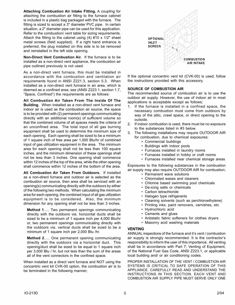
When installed as a direct vent furnace and NOT using theconcentric vent kit CVK-00 option, the combustion air is tobe terminated in the following manner;
OPTIONALINLETSCREEN
COMBUSTION AIR INTAKE
If the optional concentric vent kit (CVK-00) is used, followthe instructions provided with this accessory.
SOURCE OF COMBUSTION AIRThe recommended source of combustion air is to use theoutdoor air supply. However, the use of indoor air in mostapplications is acceptable except as follows;1. If the furnace is installed in a confined space, the
necessary combustion must come from outdoors byway of the attic, crawl space, or direct opening to theoutside.
2. If indoor combustion is used, there must be no exposureto the substances listed in #3 below.
3. The following installations may require OUTDOOR AIRfor combustion, due to chemical exposures;
� Commercial buildings� Buildings with indoor pools� Furnaces installed in laundry rooms� Furnaces installed in hobby or craft rooms� Furnaces installed near chemical storage areas
Exposures to the following substances in the combustionair supply may also require OUTDOOR AIR for combustion;
� Permanent wave solutions� Chlorinated waxes and cleaners� Chlorine based swimming pool chemicals� De-icing salts or chemicals� Carbon tetrachloride� Halogen type refrigerants� Cleaning solvents (such as perchloroethylene)� Printing inks, paint removers, varnishes, etc.� Hydrochloric acid� Cements and glues� Antistatic fabric softeners for clothes dryers� Masonry acid washing materials
VENTINGANNUAL inspections of the furnace and it�s vent / combustionair supply is strongly recommended. It is the contractor�sresponsibility to inform the user of this importance. All ventingshall be in accordance with Part 7; Venting of Equipment,of the National Fuel Gas Code, ANSI Z223.1, or applicablelocal building and/ or air conditioning codes.
PROPER INSTALLATION OF THE VENT / COMBUSTION AIRSYSTEMS IS CRITICAL TO SAFE OPERATION OF THISAPPLIANCE. CAREFULLY READ AND UNDERSTAND THEINSTRUCTIONS IN THIS SECTION. EACH VENT ANDCOMBUSTION AIR SUPPLY PIPE MUST SERVE ONLY ONE
IO-213D 2/046
APPLIANCE. DO NOT CONNECT TO AN EXISTING VENT ORCHIMNEY UNLESS IT CONFORMS TO ALL PROVISIONS INTHIS INSTRUCTION BOOKLET. THE VENT MUST TERMINATEOUTDOORS.
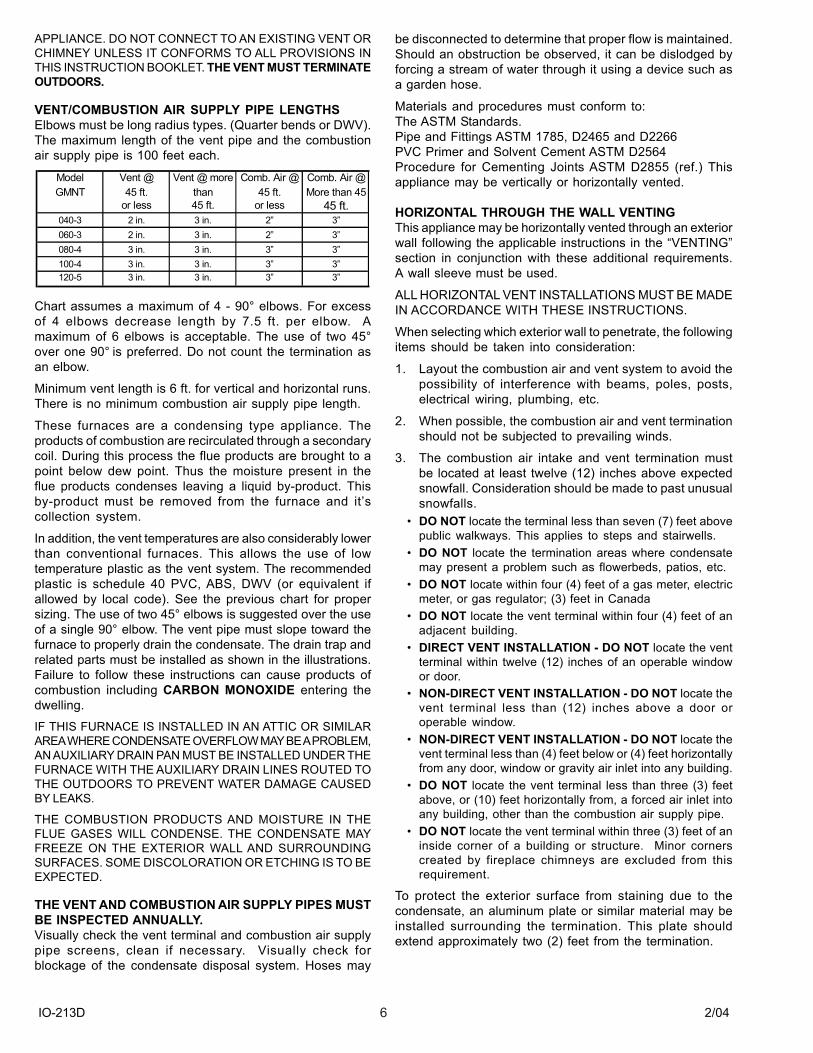
VENT/COMBUSTION AIR SUPPLY PIPE LENGTHSElbows must be long radius types. (Quarter bends or DWV).The maximum length of the vent pipe and the combustionair supply pipe is 100 feet each.
Model Vent @ Vent @ more Comb. Air @ Comb. Air @GMNT 45 ft. than 45 ft. More than 45
or less 45 ft. or less 45 ft.040-3 2 in. 3 in. 2� 3�060-3 2 in. 3 in. 2� 3�080-4 3 in. 3 in. 3� 3�100-4 3 in. 3 in. 3� 3�120-5 3 in. 3 in. 3� 3�
Chart assumes a maximum of 4 - 90° elbows. For excessof 4 elbows decrease length by 7.5 ft. per elbow. Amaximum of 6 elbows is acceptable. The use of two 45°over one 90° is preferred. Do not count the termination asan elbow.
Minimum vent length is 6 ft. for vertical and horizontal runs.There is no minimum combustion air supply pipe length.
These furnaces are a condensing type appliance. Theproducts of combustion are recirculated through a secondarycoil. During this process the flue products are brought to apoint below dew point. Thus the moisture present in theflue products condenses leaving a liquid by-product. Thisby-product must be removed from the furnace and it�scollection system.
In addition, the vent temperatures are also considerably lowerthan conventional furnaces. This allows the use of lowtemperature plastic as the vent system. The recommendedplastic is schedule 40 PVC, ABS, DWV (or equivalent ifallowed by local code). See the previous chart for propersizing. The use of two 45° elbows is suggested over the useof a single 90° elbow. The vent pipe must slope toward thefurnace to properly drain the condensate. The drain trap andrelated parts must be installed as shown in the illustrations.Failure to follow these instructions can cause products ofcombustion including CARBON MONOXIDE entering thedwelling.
IF THIS FURNACE IS INSTALLED IN AN ATTIC OR SIMILARAREA WHERE CONDENSATE OVERFLOW MAY BE A PROBLEM,AN AUXILIARY DRAIN PAN MUST BE INSTALLED UNDER THEFURNACE WITH THE AUXILIARY DRAIN LINES ROUTED TOTHE OUTDOORS TO PREVENT WATER DAMAGE CAUSEDBY LEAKS.
THE COMBUSTION PRODUCTS AND MOISTURE IN THEFLUE GASES WILL CONDENSE. THE CONDENSATE MAYFREEZE ON THE EXTERIOR WALL AND SURROUNDINGSURFACES. SOME DISCOLORATION OR ETCHING IS TO BEEXPECTED.
THE VENT AND COMBUSTION AIR SUPPLY PIPES MUSTBE INSPECTED ANNUALLY.Visually check the vent terminal and combustion air supplypipe screens, clean if necessary. Visually check forblockage of the condensate disposal system. Hoses may
be disconnected to determine that proper flow is maintained.Should an obstruction be observed, it can be dislodged byforcing a stream of water through it using a device such asa garden hose.
Materials and procedures must conform to:The ASTM Standards.Pipe and Fittings ASTM 1785, D2465 and D2266PVC Primer and Solvent Cement ASTM D2564Procedure for Cementing Joints ASTM D2855 (ref.) Thisappliance may be vertically or horizontally vented.
HORIZONTAL THROUGH THE WALL VENTINGThis appliance may be horizontally vented through an exteriorwall following the applicable instructions in the �VENTING�section in conjunction with these additional requirements.A wall sleeve must be used.
ALL HORIZONTAL VENT INSTALLATIONS MUST BE MADEIN ACCORDANCE WITH THESE INSTRUCTIONS.
When selecting which exterior wall to penetrate, the followingitems should be taken into consideration:
1. Layout the combustion air and vent system to avoid thepossibility of interference with beams, poles, posts,electrical wiring, plumbing, etc.
2. When possible, the combustion air and vent terminationshould not be subjected to prevailing winds.
3. The combustion air intake and vent termination mustbe located at least twelve (12) inches above expectedsnowfall. Consideration should be made to past unusualsnowfalls.
� DO NOT locate the terminal less than seven (7) feet abovepublic walkways. This applies to steps and stairwells.
� DO NOT locate the termination areas where condensatemay present a problem such as flowerbeds, patios, etc.
� DO NOT locate within four (4) feet of a gas meter, electricmeter, or gas regulator; (3) feet in Canada
� DO NOT locate the vent terminal within four (4) feet of anadjacent building.
� DIRECT VENT INSTALLATION - DO NOT locate the ventterminal within twelve (12) inches of an operable windowor door.
� NON-DIRECT VENT INSTALLATION - DO NOT locate thevent terminal less than (12) inches above a door oroperable window.
� NON-DIRECT VENT INSTALLATION - DO NOT locate thevent terminal less than (4) feet below or (4) feet horizontallyfrom any door, window or gravity air inlet into any building.
� DO NOT locate the vent terminal less than three (3) feetabove, or (10) feet horizontally from, a forced air inlet intoany building, other than the combustion air supply pipe.
� DO NOT locate the vent terminal within three (3) feet of aninside corner of a building or structure. Minor cornerscreated by fireplace chimneys are excluded from thisrequirement.
To protect the exterior surface from staining due to thecondensate, an aluminum plate or similar material may beinstalled surrounding the termination. This plate shouldextend approximately two (2) feet from the termination.
IO-213D 2/047
WARNINGTHE AREA SURROUNDING THE VENT TERMINAL ANDCOMBUSTION AIR SUPPLY PIPE MUST BE KEPT FREEOF SNOW, TRASH, BUSHES OR ANY OTHER OBSTACLEWHICH COULD CAUSE CARBON MONOXIDE TO ENTERTHE BUILDING.
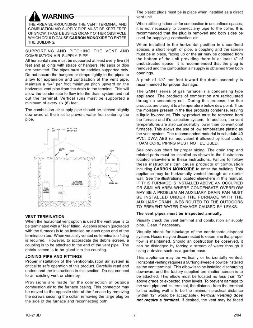
SUPPORTING AND PITCHING THE VENT ANDCOMBUSTION AIR SUPPLY PIPE.All horizontal runs must be supported at least every five (5)feet and at joints with straps or hangers. No sags or dipsare permitted. The pipes must be saddles supported only.Do not secure the hangers or straps tightly to the pipes toallow for expansion and contraction of the vent pipe.Maintain a 1/4" per foot minimum pitch upward on thehorizontal vent pipe from the drain to the terminal. This willallow the condensate to flow into the drain system and notout the terminal. Vertical runs must be supported aminimum of every six (6) feet.
The combustion air supply pipe should be pitched slightlydownward at the inlet to prevent water from entering thepipe.
VENT
COMB.AIR
12"MIN
12"/2" DIA.14"/3" DIA.
GASWATERHEATER
ALTERNATEINSTALLATION COMB. AIR
VENT
VENT TERMINATIONWhen the horizontal vent option is used the vent pipe is tobe terminated with a �Tee� fitting. A debris screen (packagedwith the furnace) is to be installed on each open end of thetermination tee. When vertically vented no termination fittingis required. However, to accoradate the debris screen, acoupling is to be attached to the end of the vent pipe. Thedebris screen is to be glued into the coupling.
JOINING PIPE AND FITTINGSProper installation of the vent/combustion air system iscritical to safe operation of this product. Carefully read andunderstand the instructions in this section. Do not connectto an existing vent or chimney.
Provisions are made for the connection of outsidecombustion air to the furnace casing. This connector maybe moved to the opposite side of the furnace by removingthe screws securing the collar, removing the large plug onthe side of the furnace and reconnecting both.
The plastic plugs must be in place when installed as a directvent unit.
When utilizing indoor air for combustion in unconfined spaces,it is not necessary to connect any pipe to the collar. It isrecommended that the plug is removed and both sides beused for supplying combustion air.
When installed in the horizontal position in unconfinedspaces, a short length of pipe, a coupling and the screenmust be in place, facing up or the air may be obtained fromthe bottom of the unit providing there is at least 4" ofunobstructed space. It is recommended that the plug isremoved and the combustion air supply is obtained from bothopenings.
A pitch of 1/4" per foot toward the drain assembly isrecommended for proper drainage.
The GMNT series of gas furnace is a condensing typeappliance. The products of combustion are recirculatedthrough a secondary coil. During this process, the flueproducts are brought to a temperature below dew point. Thusthe moisture present in the flue products condense, leavinga liquid by-product. This by-product must be removed fromthe furnace and it�s collection system. In addition, the venttemperatures are also considerably lower than conventionalfurnaces. This allows the use of low temperature plastic asthe vent system. The recommended material is schedule 40PVC, DWV, ABS (or equivalent if allowed by local code).FOAM CORE PIPING MUST NOT BE USED.
See previous chart for proper sizing. The drain trap andrelated parts must be installed as shown in the illustrationslocated elsewhere in these instructions. Failure to followthese instructions can cause products of combustionincluding CARBON MONOXIDE to enter the building. Thisappliance may be horizontally vented through an exteriorwall. See the illustrations located elsewhere in this manual.IF THIS FURNACE IS INSTALLED ABOVE AN OCCUPIEDOR SIMILAR AREA WHERE CONDENSATE OVERFLOWMAY BE A PROBLEM AN AUXILIARY DRAIN PAN MUSTBE INSTALLED UNDER THE FURNACE WITH THEAUXILIARY DRAIN LINES ROUTED TO THE OUTDOORSTO PREVENT WATER DAMAGE CAUSED BY LEAKS.
The vent pipes must be inspected annually.Visually check the vent terminal and combustion air supplypipe. Clean if necessary.
Visually check for blockage of the condensate disposalsystem. Hoses may be disconnected to determine that properflow is maintained. Should an obstruction be observed, itcan be dislodged by forcing a stream of water through itusing a device such as a garden hose.
This appliance may be vertically or horizontally vented.Horizontal venting requires a 90o long sweep elbow be installedas the vent terminal. This elbow is to be installed dischargingdownward and the factory supplied termination screen is tobe attached. This elbow must be located no less than 12"above grade or expected snow levels. To prevent damage tothe vent pipe and its terminal, the distance from the terminalto the exiting wall is to be the minimum practical distance(within 12" would be acceptable). Vertical venting doesnot require a terminal. If desired, the vent may be faced
IO-213D 2/048
downward to prevent water or other foreign objects fromentering the vent pipe. In that case, two long radius elbowsmay be employed, facing downward and terminating no lessthan one foot (1�) from the roof surface or expected snowlevel.
Protection From FreezingThe vent pipe and drain assembly must be properly protectedfrom freezing particularly if it is installed in an UNHEATEDSPACE. Low wattage tape heaters should be employed onthe drain system. The vent pipe should be insulated using aone (1) inch thick closed foam insulation if exposed to theoutdoors. For pipes located indoors or protected from theelements such as a garage, basement, etc. fiberglass withan R value of 7 or greater is acceptable.
CAUTIONDO NOT INSTALL THE VENT PIPE IN THE SAME CHASEWITH THE VENT FROM ANOTHER FUEL BURNINGAPPLIANCE, EXCEPT WITH A GMN, GMPN, GSUS, GSU,GSM, GSMS OR ANOTHER GMNT FURNACEMANUFACTURED BY GOODMAN.DO NOT INSTALL THE VENT PIPE WITHIN SIX (6) INCHESOF ANOTHER FUEL BURNING APPLIANCE.THE DRAIN TRAP MUST BE EASILY ACCESSIBLE FORCHECKING AND/OR CLEANING. IT MUST BE MOUNTEDAS SHOWN ELSEWHERE IN THESE INSTRUCTIONS.DO NOT INSTALL THE TRAP HIGHER THAN THE VENTERBLOWER OUTLET.DO NOT INSTALL THIS APPLIANCE IN ANY AREA WHEREFREEZING MAY OCCUR WITHOUT PROPERLYPROTECTING THE DRAIN ASSEMBLY.DO NOT TERMINATE THE VENT UNDER A DECK,OVERHANG OR IN A POSITIVE PRESSURE AREA. THERECIRCULATION OF VENT PRODUCTS MAY OCCUR.
CONSULT LOCAL CODES FOR SPECIAL ADDITIONALREQUIREMENT.
THE COMBUSTION PRODUCTS IN THE FLUE GASES WILLCONDENSE. THE CONDENSATE MAY FREEZE ON THEEXTERIOR WALL AND SURROUNDING SURFACES. SOMEDISCOLORATION OR ETCHING IS TO BE EXPECTED.
When selecting which exterior wall to penetrate, thefollowing items should be taken into consideration:
1. Layout the vent system to avoid the possibility ofinterference with beams, poles, posts, electrical wiring,plumbing, etc.
2. When possible, the vent termination/combustion airsupply pipe should not be subjected to prevailing winds.
3. The vent terminal must be located at least twelve (12)inches above grade or expected snow depth.Consideration should be given to past unusual snowfalls.
4. To protect the exterior surface from staining due to thecondensate, an aluminum plate or similar material maybe installed surrounding the termination. This plateshould extend approximately two (2) feet around thepenetration.
CONDENSATE DRAINThis furnace is designed to remove both sensible and latentheat from the combustion products. As a result water vaporis condensed in the secondary heat exchanger. Thiscondensate must be drained either to the outdoors or, wherelocal code permits, to a sewage system.
In areas where floor level drains are not available, acondensate pump may be employed. This condensatepump must be constructed of corrosion resistant materials.It must also have an auxiliary switch that will shut down thefurnace in the event of a pump failure or drain tube blockage.
DO NOT run the condensate drain to an outdoor drain or toan unheated area where the possibility of freezing mayoccur.
Note: Some locals require the condensate to be neutralized.Check local codes.
IO-213D 2/049
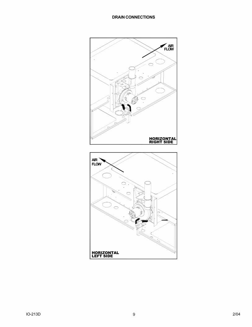
DRAIN CONNECTIONS
HORIZONTALRIGHT SIDE
HORIZONTALLEFT SIDE
AIRFLOW
AIRFLOW
IO-213D 2/0410
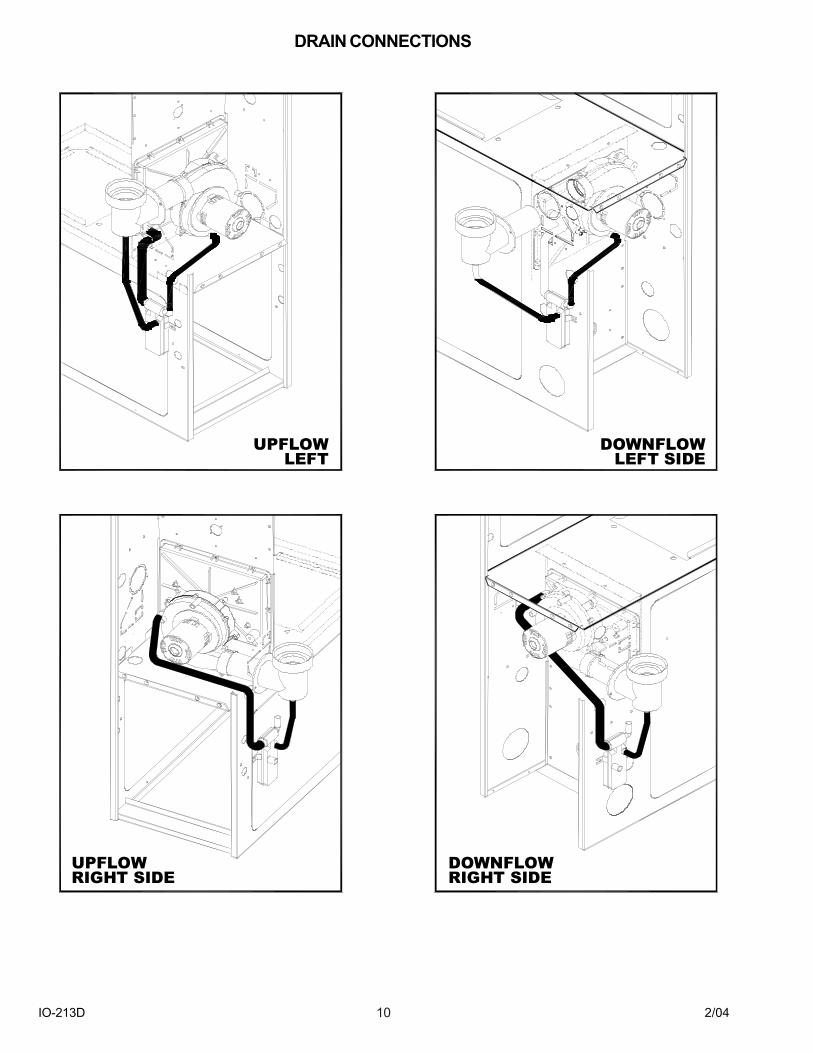
DRAIN CONNECTIONS
UPFLOWLEFT
DOWNFLOWLEFT SIDE
DOWNFLOWRIGHT SIDE
UPFLOWRIGHT SIDE
IO-213D 2/0411
GAS PIPING & GAS PIPE CAPACITY TABLECheck the rating plate to make certain that the gas suppliedis compatible with the unit requirements. Care should betaken after the installation of this appliance that the gascontrol valve is not subjected to high gas supply linepressure. In making connections, avoid strains as they maycause noise and damage the controls. Always use a back-up wrench when tightening the gas supply pipe to the gascontrol valve. Check for leaks in the gas supply using soapbubbles or other approved methods.
NEVER USE AN OPEN FLAME TO CHECK FOR GASLEAKS. THIS PRACTICE MAY CAUSE A FIRE,EXPLOSION, BODILY HARM OR PROPERTY DAMAGE.
Pipe joint compound must be resistant to the action of L.P.gas. When connecting the gas service to the furnace, aground joint union and manual shutoff must be installedexterior to the furnace cabinet and located in the same roomso the control assembly may be easily removed.
A 1/8" NPT plug on the supply pipe near the manual valvefor the purpose of making pressure measurement shouldalso be installed. The valve should be readily accessible forturning on or off. A capped sediment trap, sometimes calleda drip leg, must be installed in the gas supply pipe as closeto the furnace as possible. The sediment trap mustincorporate a change of gas flow direction.
Refer to local codes or the previously mentioned publicationsfor proper location and size of the manual shutoff andsediment trap lengths.
The gas pipe must be sized to eliminate undue pressuredrop. See pipe capacity table or consult your local utility.Both the supply and manifold pressure must be measuredwith the furnace running using the field supplied pressuretap near the manual shut-off valve and the pressure adjustedif necessary.
All gas piping must conform to local codes, or in the absenceof local codes, to the National Fuel Gas Code ANSI Z223.1and / or CAN/CGA B149 Installation Codes.
Note: Copper tubing must not be used for natural gasinstallations where more than .3 grains of hydrogen sulfideper 100 standard cubic feet of gas is present. (If thequantities of hydrogen sulfide cannot be verified, do not usecopper).
FOR INSTALLATIONS IN THE COMMONWEALTH OFMASSACHUSETTS SEE FUEL GAS AND PLUMBINGCODE 248 CMR: APPENDIX C.
P ip e S iz e * ½ ¾ 1 1 ¼ 1 ½
1 0 1 3 2 2 7 8 5 2 0 1 0 5 0 1 6 0 02 0 9 2 1 9 0 3 5 0 7 3 0 1 1 0 0
L e n g th 3 0 7 3 1 5 2 2 8 5 5 9 0 8 9 0o f 4 0 6 3 1 3 0 2 4 5 5 0 0 7 6 0P ip e 5 0 5 6 1 1 5 2 1 5 4 4 0 6 7 0in F e e t 6 0 5 0 1 0 5 1 9 5 4 0 0 6 1 0
7 0 4 6 9 6 1 8 0 3 7 0 5 6 08 0 4 3 9 0 1 7 0 3 5 0 5 3 0
*N o m in a l s iz e o f iro n p ip e in in c h e s .
C a p a c ity o f g a s p ip e o f d if fe re n t d ia m e te rs a n d le n g th in f t3 /h r . w ith a p re s s u re d ro p o f 0 .3 " W .C . a n d a s p e c if ic
g ra v ity o f 0 .6 0 (n a tu ra l g a s ) .
After the length of pipe has been determined, select thepipe size, which will provide the minimum cubic feet per
hour of gas flow for the required input of the appliance. Inthe case where more than one appliance utilizes the samesupply pipe be sure to consider the sum of all appliances.The cubic feet of gas required for the appliances should bedetermined using the following formula;
Cubic feet of Gas input of appliance (BTU/hr.)
gas required Heating value of gas (BTU/hr.)
The gas input of the appliance is marked on the specificationplate. The heating value of the gas may be determined bycontacting the gas utility or gas supplier.
CAUTIONIF THE LOCAL UTILITY PERMITS THE USE OF A FLEXIBLEGAS CONNECTOR - ALWAYS USE A NEW FLEXIBLECONNECTOR. DO NOT USE FLEXIBLE GAS LINES THATHAVE SERVICED ANOTHER APPLIANCE. AFTER A PERIODOF TIME THESE LINES MAY BECOME BRITTLE AND CANDEVELOP LEAKS. THE CONNECTIONS TO A FLEXIBLEGAS LINE MUST BE MADE OUTSIDE OF THE FURNACECABINET.
CIRCULATING AIR SUPPLY AND RETURN AIRThe circulating air supply may be taken from; 1) Outsidethe building, 2) return ducts from several rooms, 3) centralreturn, 4) any combination of the above.
When a cooling coil is not installed it is recommended thatthe supply duct have an access panel so the heat exchangercan be viewed. This panel shall be of sufficient size to permitthe entrance of a light or probe to assist in the observationof the heat exchanger integrity or sampling the air stream.It should be sealed to prevent air leakage during normaloperation.
Return air from one dwelling shall not be discharged intoanother dwelling through the heating system.
There shall be a positive separation between combustionair and return air.
Do not obtain return air from a hazardous or insanitarylocation or a refrigeration machinery room or any room orspace having any fuel-burning appliances therein.
CAUTIONDO NOT TAKE RETURN AIR FROM BATHROOMS,KITCHENS, FURNACE ROOMS, GARAGES, UTILITY/LAUNDRY ROOMS OR COLD AREAS. IF OUTSIDE AIR ISUTILIZED, IT SHOULD NOT BE TAKEN FROM WITHIN 10FEET OF AN APPLIANCE VENT OUTLET, A VENT OPENINGOR A PLUMBING DRAINAGE SYSTEM, OR THE DISCHARGEFROM AN EXHAUST SYSTEM UNLESS THE OUTLET ISTHREE (3) FEET ABOVE THE OUTSIDE AIR INLET. DONOT TAKE RETURN AIR FROM AN AREA WHERE IT CANPICK-UP OBJECTIONABLE ODORS, FUMES, ORFLAMMABLE VAPORS.
Note: When a combination of outdoor and indoor air isutilized the system should be designed and adjusted suchthat the temperature reaching the appliance will not dropbelow 50o F during heating operation. This will minimize thepossibility of condensate forming inside the heat exchanger.When this type of system is utilized the volume of air mustnot be reduced.
=
IO-213D 2/0412
Plenum chambers and air ducts must be installed inaccordance with the Standard for the Installation of AirConditioning and Ventilating Systems, NFPA #90A, or theStandard for the Installation of Warm Air Heating and AirConditioning Systems, NFPA # 90B.
If installed in parallel with a cooling unit the damper or othermeans used to control the flow of air must be adequate toprevent chilled air from entering the furnace, and if manuallyoperated must be equipped with means to prevent operationof the other unit unless the damper is in the full heat or coolposition.
NOTE: UPON INITIAL START-UP SOME SMOKE OR AN ODORMAY BE PRESENT. THIS IS NORMAL AND SHOULDDISAPPEAR IN A SHORT AMOUNT OF TIME. IT ISRECOMMENDED THAT WINDOWS AND DOORS BE OPENEDUPON INITIAL START-UP TO VENT THIS NON-TOXIC SMOKE.
One of the most common causes of problems, includingpremature heat exchanger failure, in a forced air heatingsystem is insufficient return air. The return air connectionsto the furnace should be approximately equal to the area ofwarm air discharge. Consult local codes for specificrequirements.
All return ducts must be adequately secured to the furnaceand sealed airtight. All other ductwork must be secured withapproved connections and sealed airtight.
When the furnace is mounted on a platform it must be sealedair tight between the furnace and the return ductwork. Thefloor or platform must provide sound physical support forthe furnace without cracks, gaps, sagging, etc. around thebase as to provide an airtight seal between the support andthe base.
Install the return air to terminate through the base under thefurnace. For installations where return air ducts cannot berun under the floor, the return air supply may be taken fromthe side(s).
Embosses are provided on the sides of the furnace for useas a template for the ductwork connection.
Where the maximum required airflow is 1800 c.f.m. orgreater, the bottom or both sides must be utilized for returnair supply. Never use the rear of the furnace for the returnconnection unless it is for conditions where additional returnair ducts are desired.
ELECTRICAL SUPPLY CONNECTIONSThe electrical requirements are 115Volts, 60 Hz., 1 Ph. Aseparate supply line with a current overload device and amanual switch, where required, must be installed. Type �T�wire or equivalent with a minimum rating of 95oF (35oC)temperature rise must be run directly from the main powersupply. Use copper conductors only.
Holes are provided on both sides of the furnace for electricalconnection. The junction box may be moved to either side.The entry holes for supply and low voltage control wires arefor use with ½� electrical connectors.
All electrical wiring entering the furnace must be secured tothe casing with proper methods of strain relief. Solderlessconnectors may be used to connect wires inside the junctionbox for supply wires.
It is recommended that a means of shutting off the powerbe within sight of the furnace.
INSTALLATION OF THE ELECTRICAL SUPPLY MUST BE INACCORDANCE WITH LOCAL CODES. IN THE ABSENCEOF LOCAL CODES REFER TO THE NATIONALELECTRICAL CODE ANSI/NFPA NO. 7 (LATEST EDITION),WHICH CAN BE OBTAINED FROM THE NATIONAL FIREPROTECTION ASSOCIATION, BATTERYMARCH PARK,QUINCY, MA 02269. IN CANADA REFER TO THE LATESTEDITION OF THE CANADIAN ELECTRICAL CODE C22.1PART I.
CONTROL VOLTAGE CONNECTIONSThermostat InstallationInstall the thermostat in accordance with the instructionsaccompanying the thermostat. Connect the thermostatwiring to the thermostat terminal block on the furnace controlboard. The thermostat wiring should be a minimum of 18gauge. Adhere to recommended color code to facilitatefuture troubleshooting.
The thermostat should be located near the return air grilleor opening. It should be approximately 5 feet from the floorlevel. Never locate the thermostat where it will be influencedby heat generated by hot water pipes, lamps, televisions,direct sunlight, supply air registers, etc.
Interconnecting wiring must be secured and protected fromdamage or disconnection. The use of solderless connectorsor equivalent is recommended. The low voltage control wiringexiting the furnace is labeled �thermostat wiring�.
Setting The Heat AnticipatorFollowing the instructions accompanying the thermostat forproper adjustment of the anticipator.
FEATURESThe integrated control board in this furnace has terminalsprovided for added features. These features are a 115v.Humidifier, a 24v. Humidifier, an Electronic Air Cleaner, Blower�OFF� Timing and Twinning with another furnace.
115 Volt HumidifierThe �115v HUM� terminal is located on the high voltage sideof the board. It is covered with a terminal protector. Seewiring below.
24 Volt HumidifierThe �HUM� lug for the operation of a 24-volt humidifier islocated in the vicinity of the thermostat connections. Seewiring.
HUM
IGNITION CONTROLFIELD SUPPLIEDHUMIDISTATHUMIDIFIER
LINENEUTRAL
Electronic Air CleanerThe E.A.C. terminal is located near the blower speedconnections and is covered with a terminal protector. Thisoption should be wired in conjunction with the electronic aircleaner. This feature assures the indoor blower fan isenergized when there is a demand for air cleaner.
IO-213D 2/0413
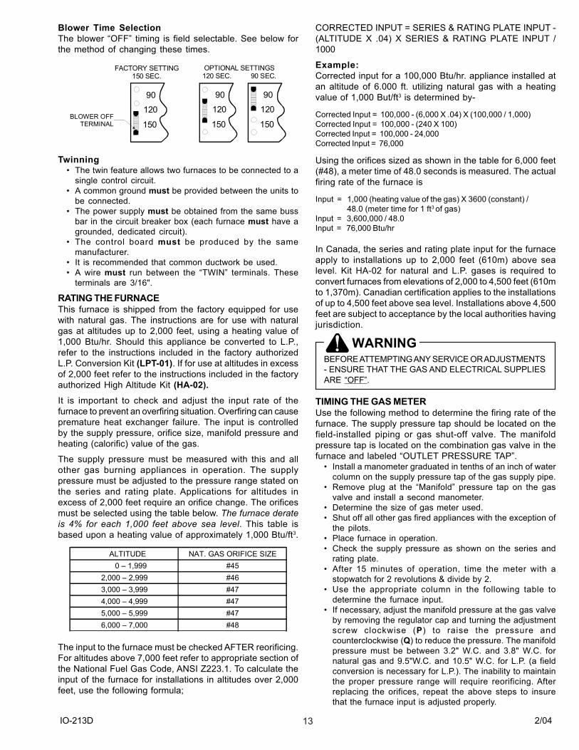
Blower Time SelectionThe blower �OFF� timing is field selectable. See below forthe method of changing these times.
BLOWER OFFTERMINAL
90
120
150
FACTORY SETTING150 SEC.
OPTIONAL SETTINGS120 SEC. 90 SEC.
90
120
150
90
120
150
Twinning� The twin feature allows two furnaces to be connected to a
single control circuit.� A common ground must be provided between the units to
be connected.� The power supply must be obtained from the same buss
bar in the circuit breaker box (each furnace must have agrounded, dedicated circuit).
� The control board must be produced by the samemanufacturer.
� It is recommended that common ductwork be used.� A wire must run between the �TWIN� terminals. These
terminals are 3/16".
RATING THE FURNACEThis furnace is shipped from the factory equipped for usewith natural gas. The instructions are for use with naturalgas at altitudes up to 2,000 feet, using a heating value of1,000 Btu/hr. Should this appliance be converted to L.P.,refer to the instructions included in the factory authorizedL.P. Conversion Kit (LPT-01). If for use at altitudes in excessof 2,000 feet refer to the instructions included in the factoryauthorized High Altitude Kit (HA-02).It is important to check and adjust the input rate of thefurnace to prevent an overfiring situation. Overfiring can causepremature heat exchanger failure. The input is controlledby the supply pressure, orifice size, manifold pressure andheating (calorific) value of the gas.
The supply pressure must be measured with this and allother gas burning appliances in operation. The supplypressure must be adjusted to the pressure range stated onthe series and rating plate. Applications for altitudes inexcess of 2,000 feet require an orifice change. The orificesmust be selected using the table below. The furnace derateis 4% for each 1,000 feet above sea level. This table isbased upon a heating value of approximately 1,000 Btu/ft3.
ALTITUDE NAT. GAS ORIFICE SIZE 0 � 1,999 #452,000 � 2,999 #463,000 � 3,999 #474,000 � 4,999 #475,000 � 5,999 #476,000 � 7,000 #48
The input to the furnace must be checked AFTER reorificing.For altitudes above 7,000 feet refer to appropriate section ofthe National Fuel Gas Code, ANSI Z223.1. To calculate theinput of the furnace for installations in altitudes over 2,000feet, use the following formula;
CORRECTED INPUT = SERIES & RATING PLATE INPUT -(ALTITUDE X .04) X SERIES & RATING PLATE INPUT /1000
Example:Corrected input for a 100,000 Btu/hr. appliance installed atan altitude of 6.000 ft. utilizing natural gas with a heatingvalue of 1,000 But/ft3 is determined by-
Corrected Input = 100,000 - (6,000 X .04) X (100,000 / 1,000)Corrected Input = 100,000 - (240 X 100)Corrected Input = 100,000 - 24,000Corrected Input = 76,000
Using the orifices sized as shown in the table for 6,000 feet(#48), a meter time of 48.0 seconds is measured. The actualfiring rate of the furnace is
Input = 1,000 (heating value of the gas) X 3600 (constant) / 48.0 (meter time for 1 ft3 of gas)Input = 3,600,000 / 48.0Input = 76,000 Btu/hr
In Canada, the series and rating plate input for the furnaceapply to installations up to 2,000 feet (610m) above sealevel. Kit HA-02 for natural and L.P. gases is required toconvert furnaces from elevations of 2,000 to 4,500 feet (610mto 1,370m). Canadian certification applies to the installationsof up to 4,500 feet above sea level. Installations above 4,500feet are subject to acceptance by the local authorities havingjurisdiction.
WARNINGBEFORE ATTEMPTING ANY SERVICE OR ADJUSTMENTS- ENSURE THAT THE GAS AND ELECTRICAL SUPPLIESARE �OFF�.
TIMING THE GAS METERUse the following method to determine the firing rate of thefurnace. The supply pressure tap should be located on thefield-installed piping or gas shut-off valve. The manifoldpressure tap is located on the combination gas valve in thefurnace and labeled �OUTLET PRESSURE TAP�.
� Install a manometer graduated in tenths of an inch of watercolumn on the supply pressure tap of the gas supply pipe.
� Remove plug at the �Manifold� pressure tap on the gasvalve and install a second manometer.
� Determine the size of gas meter used.� Shut off all other gas fired appliances with the exception of
the pilots.� Place furnace in operation.� Check the supply pressure as shown on the series and
rating plate.� After 15 minutes of operation, time the meter with a
stopwatch for 2 revolutions & divide by 2.� Use the appropriate column in the following table to
determine the furnace input.� If necessary, adjust the manifold pressure at the gas valve
by removing the regulator cap and turning the adjustmentscrew clockwise (P) to raise the pressure andcounterclockwise (Q) to reduce the pressure. The manifoldpressure must be between 3.2" W.C. and 3.8" W.C. fornatural gas and 9.5"W.C. and 10.5" W.C. for L.P. (a fieldconversion is necessary for L.P.). The inability to maintainthe proper pressure range will require reorificing. Afterreplacing the orifices, repeat the above steps to insurethat the furnace input is adjusted properly.
IO-213D 2/0414
� Turn off gas and electrical supply, remove manometersand replace any plugs, which were removed. Use a pipejoint compound, which is suitable for use with L.P. gas.
� Restore any other appliances affected to their normaloperating mode.
METER TIME IN MINUTES AND SECONDS FOR NORMALINPUT RATING OF FURNACES EQUIPPED FOR USEWITH NATURAL GAS AT 0 - 2,000 FEET ALTITUDE.
INPUT METER SIZE
HEAT VALUE
HEAT VALUE
HEAT VALUE
HEAT VALUE
Btu/hr FT3 900 1,000 1040 1,100MIN. SEC. MIN.SEC MIN. SEC. MIN. SEC.
1 1 21 1 30 1 33 1 3910 13 30 15 00 15 36 16 301 0 54 1 00 1 03 1 0610 9 00 10 10 10 24 11 001 0 41 0 45 0 47 0 5010 6 45 7 30 7 48 8 151 0 32 0 36 0 37 0 4010 5 24 6 00 6 14 6 361 0 27 0 30 0 31 0 3310 4 30 5 00 5 12 5 30
120,000
40,000
60,000
80,000
100,000
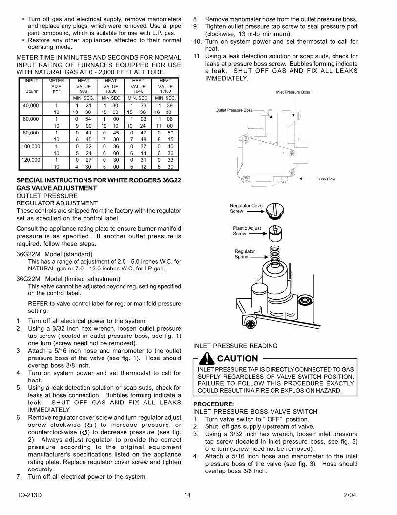
SPECIAL INSTRUCTIONS FOR WHITE RODGERS 36G22GAS VALVE ADJUSTMENTOUTLET PRESSUREREGULATOR ADJUSTMENTThese controls are shipped from the factory with the regulatorset as specified on the control label.
Consult the appliance rating plate to ensure burner manifoldpressure is as specified. If another outlet pressure isrequired, follow these steps.
36G22M Model (standard)This has a range of adjustment of 2.5 - 5.0 inches W.C. forNATURAL gas or 7.0 - 12.0 inches W.C. for LP gas.
36G22M Model (limited adjustment)This valve cannot be adjusted beyond reg. setting specifiedon the control label.
REFER to valve control label for reg. or manifold pressuresetting.
1. Turn off all electrical power to the system.2. Using a 3/32 inch hex wrench, loosen outlet pressure
tap screw (located in outlet pressure boss, see fig. 1)one turn (screw need not be removed).
3. Attach a 5/16 inch hose and manometer to the outletpressure boss of the valve (see fig. 1). Hose shouldoverlap boss 3/8 inch.
4. Turn on system power and set thermostat to call forheat.
5. Using a leak detection solution or soap suds, check forleaks at hose connection. Bubbles forming indicate aleak. SHUT OFF GAS AND FIX ALL LEAKSIMMEDIATELY.
6. Remove regulator cover screw and turn regulator adjustscrew clockwise (!!!!! ) to increase pressure, orcounterclockwise (""""") to decrease pressure (see fig.2). Always adjust regulator to provide the correctpressure according to the original equipmentmanufacturer's specifications listed on the appliancerating plate. Replace regulator cover screw and tightensecurely.
7. Turn off all electrical power to the system.
8. Remove manometer hose from the outlet pressure boss.9. Tighten outlet pressure tap screw to seal pressure port
(clockwise, 13 in-lb minimum).10. Turn on system power and set thermostat to call for
heat.11. Using a leak detection solution or soap suds, check for
leaks at pressure boss screw. Bubbles forming indicatea leak. SHUT OFF GAS AND FIX ALL LEAKSIMMEDIATELY.
Outlet Pressure Boss
Inlet Pressure Boss
Gas Flow
Regulator Cover Screw
Plastic AdjustScrew
Regulator Spring
INLET PRESSURE READING
CAUTIONINLET PRESSURE TAP IS DIRECTLY CONNECTED TO GASSUPPLY REGARDLESS OF VALVE SWITCH POSITION.FAILURE TO FOLLOW THIS PROCEDURE EXACTLYCOULD RESULT IN A FIRE OR EXPLOSION HAZARD.
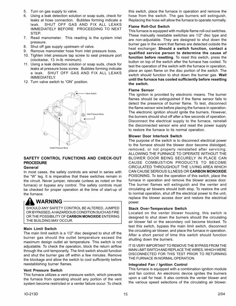
PROCEDURE:INLET PRESSURE BOSS VALVE SWITCH1. Turn valve switch to � OFF� position.2. Shut off gas supply upstream of valve.3. Using a 3/32 inch hex wrench, loosen inlet pressure
tap screw (located in inlet pressure boss, see fig. 3)one turn (screw need not be removed).
4. Attach a 5/16 inch hose and manometer to the inletpressure boss of the valve (see fig. 3). Hose shouldoverlap boss 3/8 inch.
IO-213D 2/0415
5. Turn on gas supply to valve.6. Using a leak detection solution or soap suds, check for
leaks at hose connection. Bubbles forming indicate aleak. SHUT OFF GAS AND FIX ALL LEAKSIMMEDIATELY BEFORE PROCEEDING TO NEXTSTEP.
7. Read manometer. This reading is the system inletpressure.
8. Shut off gas supply upstream of valve.9. Remove manometer hose from inlet pressure boss.10. Tighten inlet pressure tap screw to seal pressure port
(clockwise, 13 in-lb minimum).11. Using a leak detection solution or soap suds, check for
leaks at pressure boss screw. Bubbles forming indicatea leak. SHUT OFF GAS AND FIX ALL LEAKSIMMEDIATELY.
12. Turn valve switch to �ON� position.
Outlet Pressure Boss
Inlet Pressure Boss
Valve Switch
SAFETY CONTROL FUNCTIONS AND CHECK-OUTPROCEDUREGeneralIn most cases, the safety controls are wired in series withthe �W� leg. It is imperative that these switches remain inthe circuit. Never jumper, relocate (unless as noted on thefurnace) or bypass any control. The safety controls mustbe checked for proper operation at the time of start-up ofthe furnace.
WARNINGSHOULD ANY SAFETY CONTROL BE ALTERED, JUMPEDOR BYPASSED, A HAZARDOUS CONDITION SUCH AS FIREOR THE POSSIBILITY OF CARBON MONOXIDE ENTERINGTHE BUILDING MAY OCCUR.
Main Limit SwitchThe main limit switch is a 1/2" disc designed to shut off theburner gas should the outlet temperature exceed themaximum design outlet air temperature. This switch is notadjustable. To check the operation, block the return airflowthrough the unit temporarily. The limit switch should functionand shut the burner gas off within a few minutes. Removethe blockage and allow the switch to cool sufficiently beforereestablishing burner flames.
Vent Pressure SwitchThis furnace utilizes a vent pressure switch, which preventsthe furnace from operating should any portion of the ventsystem become restricted or a venter failure occur. To check
this switch, place the furnace in operation and remove thehose from the switch. The gas burners will extinguish.Replacing the hose will allow the furnace to operate normally.
Flame Roll-Out SwitchThis furnace is equipped with multiple flame roll-out switches.These manually resetable switches are 1/2" disc type andare non-adjustable. They are designed to shut down theburner gas in the event that flames are detected outside theheat exchanger. Should a switch function, contact aqualified service person to determine the cause offunction before resetting. To reset this switch, press thebutton on top of the switch after the furnace has cooled. Totest the operation of the switch with the furnace in operation,place an open flame on the disc portion of the switch. Theswitch should function to shut down the burner gas. Waituntil the furnace has cooled sufficiently before resettingthe switch.Flame SensorThe ignition is provided by electronic means. The burnerflames should be extinguished if the flame sensor fails todetect the presence of burner flame. To test, disconnectthe flame sensor wire before placing the furnace in operation.The electronic ignition should ignite the burners. However,the burners should shut off after a few seconds of operation.Disconnect the electrical supply to the furnace, reinstallthe disconnected sensor wire and reset the power supplyto restore the furnace to its normal operation.
Blower Door Interlock SwitchThe purpose of the switch is to disconnect electrical powerto the furnace should the blower door become dislodged,removed, or not properly reinstalled after servicing.ALLOWING THE FURNACE TO OPERATE WITHOUT THEBLOWER DOOR BEING SECURELY IN PLACE CANCAUSE COMBUSTION PRODUCTS TO BECOMECIRCULATED THROUGHOUT THE LIVING AREA WHICHCAN CAUSE SERIOUS ILLNESS OR CARBON MONOXIDEPOISONING. To test the operation of this switch, place thefurnace in operation and remove the blower access door.The burner flames will extinguish and the venter andcirculating air blowers should both stop. To restore the unitto normal operation, shut off the electrical power to the unit,replace the blower access door and restore the electricalpower.
Stack Over-Temperature SwitchLocated on the venter blower housing, this switch isdesigned to shut down the burners should the circulatingair blower fail or the secondary coil become blocked. Totest this switch, bypass the main limit switch, disconnectthe circulating air blower, and place the furnace in operation.After a short period of time this switch should functionshutting down the burners.
IT IS VERY IMPORTANT TO REMOVE THE BYPASS FROM THEMAIN LIMIT SWITCH AND REPLACE THE WIRES, WHICH WEREDISCONNECTED FOR THIS TEST PRIOR TO RETURNINGTHE FURNACE IN NORMAL OPERATION.
Integrated Fan / Ignition ControlThis furnace is equipped with a combination ignition moduleand fan control. An electronic device ignites the burnersupon a call for heat. It also controls the venter blower andthe various speed selections of the circulating air blower.
IO-213D 2/0416
This control is located in the circulating air blowercompartment. Upon a demand for heat, the venter isenergized. After a short purge, the electronic ignition deviceis energized. The burners are ignited after a short delay andthe burner flame is proven. The circulating air blower isenergized at approximately 30 seconds after the burnersare ignited. The circulating air blower off time is fieldselectable at 90, 120 or 150 seconds. THIS CONTROL ISNOT FIELD SERVICEABLE.
CIRCULATING AIR FILTERSOne of the most common causes of problems in a forcedair heating system is blocked or dirty filters. Circulating airfilters must be inspected monthly for dirt accumulation andreplaced if necessary. Failure to maintain clean filters cancause premature heat exchanger failure. A new home mayrequire more frequent replacement until all construction dustand dirt is removed. Circulating air filters must be installedexternal to the furnace cabinet.
CAUTIONBEFORE PERFORMING ANY SERVICE ON THIS FURNACE,DISCONNECT THE MAIN POWER SUPPLY.
CAUTIONDO NOT OPERATE THE FURNACE WITHOUT THECIRCULATING AIR FILTERS IN PLACE. DUST AND DIRT INTHE AIR WILL RESTRICT THE AIR MOVEMENT OVER THESECONDARY COIL CAUSING NUISANCE CYCLING OFSAFETY CONTROLS, WHICH MAY RESULT IN A �NO HEATCONDITION.�
TEMPERATURE RISEThe temperature difference between the outlet air and theinlet air of the furnace is known as the temperature rise.This furnace is designed to operate within the temperaturerise displayed on the furnace series and rating plate. Toensure satisfactory performance, the temperature rise ofthe furnace must be measured and adjusted if necessary.Use the following procedure to measure and adjust thetemperature rise;
� Prior to starting the furnace, visually inspect all joints andseams in the supply and return air ducts for leaks. Repairthem if necessary.
� Adjust the room thermostat to obtain constant operation.� Allow the furnace to operate for at least fifteen (15) minutes.� With an accurate thermometer, measure the temperature
at the return air grille. If a combination indoor / outdoorsystem is used, the temperature must be measureddownstream of the connection.
� Measure the outlet air temperature at a point approximatelytwelve to eighteen (12 -18) inches from the supply air ductopening of the furnace. It may be necessary to measurethe outlet air at several places to obtain an accurateaverage. NOTE: IF AN AIR CONDITIONING COIL ISINSTALLED, TAKE CARE SO AS NOT TO DAMAGE THATCOIL.
� Adjust the temperature rise by changing circulating airblower speed tap.
MOTOR LUBRICATION AND MAINTENANCEThe circulating air blower is equipped with bearings that arepermanently lubricated by the motor manufacturer andrequire no additional lubrication. At the time of the monthlyfilter inspection, clean the exterior of the circulating air motor,
especially around the perimeter air holes to prevent thepossibility of overheating due to an accumulation of dust ordirt on the windings and motor casing. As suggestedelsewhere in these instructions, the air filters are to be keptclean. Dirty filters will restrict the airflow over the motorwindings and possibly cause an overheating condition. Theventer motor has bearings that are prelubricated by the motormanufacturer and require no attention.
SERVICE INSTRUCTIONS� DO keep the circulating air filters clean. The heating system
will operate more efficiently and economically.� DO arrange drapes and furniture so that the supply air
registers and return air grilles are unobstructed.� DO close doors and windows. This will reduce the heat
load on the system.� DO avoid excessive use of bathroom and kitchen exhaust
fans.� DO NOT let heat generated by televisions, lamps, direct
sunlight, etc. influence the thermostat operation.� DO NOT use the furnace room as a storage area.� DO NOT store gasoline or other flammable liquids or vapors
in the vicinity of the furnace.� EXCLUSIVE of the mounting platform, keep all
combustible materials at least 3 feet from the Furnace.
SEQUENCE OF OPERATIONThis appliance is controlled by the thermostat. Within thissection, the term lockout is referenced. This lockout is a�soft� lockout, which will reset after one hour. It is theobligation of the installer to educate the user on the properuse of the thermostat and the sequence of operation in boththe heating and cooling modes. It is also important that anyrepair or service be performed by a QUALIFIED serviceperson, not by the user.
Heating Mode� The furnace control checks for an open main limit (this
limit is normally closed). If the limit is open, the furnacewill remain inoperable until the limit is closed. During anopen limit, the circulating air blower will be energized. Thestatus light will blink four (4) times.
� The room thermostat reacts to a demand for heat.� The control will then check to insure that the vent pressure
switch is open. If, at this point, the vent pressure switch isclosed, the control will blink two (2) times and will remaininoperable until this situation is corrected.
� The venter blower is energized.� The vent pressure switch will close when it detects a
pressure in excess of its setting. If the pressure switchfails to close, the status light will flash three (3) times. Thesequence cannot continue until the pressure switch closes.
� After a pre-purge of about fifteen (15) seconds, theelectronic ignition device will be energized.
� The flame rollout switches are then checked to assurethey are in the closed position.
� After a slight delay, the gas valve will open if the flamerollout switches are closed.
� The burners will ignite and the flame sensor will detect thepresence of flame. The ignition device will deenergize. Ifthe sensor does not detect the burner flame, the gas valvewill close and the ignition cycle will be repeated for a totalof three attempts. If, after the third attempt, the presence offlame is not detected, the furnace will go into a lockoutcondition for one (1) hour. It will then repeat the ignitioncycle. This one (1) hour lockout and retry will occurindefinitely.
IO-213D 2/0417
� Thirty (30) seconds after the main valve is energized thecirculating air blower will be activated.
� The furnace will remain in operation until the demand forheat is satisfied.
� Once the demand is satisfied the venter will shut off, andthe circulating air blower will shut off after the fieldselectable time off is attained.
� The furnace will remain dormant until the next demand forheat.
Cooling Mode� The control checks for an open limit. If an open limit is
detected, the furnace will remain inoperable until thecondition is corrected. During an open limit condition, thecirculating air blower will be energized. The status lightwill blink four (4) times.
� A demand for cooling is initiated.� The condenser contactor will close.� After approximately five (5) seconds, the circulating air
blower will start on the cooling speed.� After the room thermostat is satisfied, the condenser
contactor will open.� The circulating air blower will remain in operation for
approximately sixty (60) seconds.
REMOVING AN EXISTING APPLIANCEWhen replacing an existing appliance, the resultinginstallation must comply with all local codes, or in theabsence of local codes, to the National Fuel Gas CodesANSI Z223.1 and/or CAN/CGA B149 Installation Codes aswell as these installation instructions.
If the installation of this GMNT furnace requires that anexisting appliance be removed from a venting system, whichstill serves another gas, fired appliance, this may requirethat the existing vent be re-sized. The following steps shallbe performed with each appliance connected to the ventingsystem placed in operation while any other applianceconnected to the venting system are not in operation;
a. Sealing unused openings in the venting system;b. Inspect the venting system for proper size and horizontal
pitch, as required in the National Fuel Gas Code, ANSIZ223.1 or the CAN/CGA B149 Installation Codes and theseinstructions. Determine that there is no blockage orrestriction, leakage, corrosion and other deficiencies,which could cause an unsafe condition;
c. In so far as practical, close all building doors and windowsand all doors between the space in which the appliance(s)connected to the venting system are located and otherspaces in the building. Turn on clothes dryers and anyother appliance not connected to the venting system. Turnon any exhaust fans such as range hoods and bathroomexhausts, so they shall operate at their maximum speed.DO NOT operate a summer exhaust fan (whole housefan). Close fireplace dampers;
d. Follow lighting instructions. Place the appliance beinginspected in operation. Adjust the thermostat so theappliance shall operate continuously;
e. Test for draft hood equipped appliance spillage at the reliefopening after five (5) minutes of burner operation. Use theflame of a match or candle;
f. After it has been determined that each appliance connectedto the venting system properly vents when tested asoutlined above, return all doors, windows, exhaust fans,fireplace dampers and any other gas-burning applianceback to their previous condition of use;
g. If improper venting is observed during any of the abovetests, the venting system must be corrected.
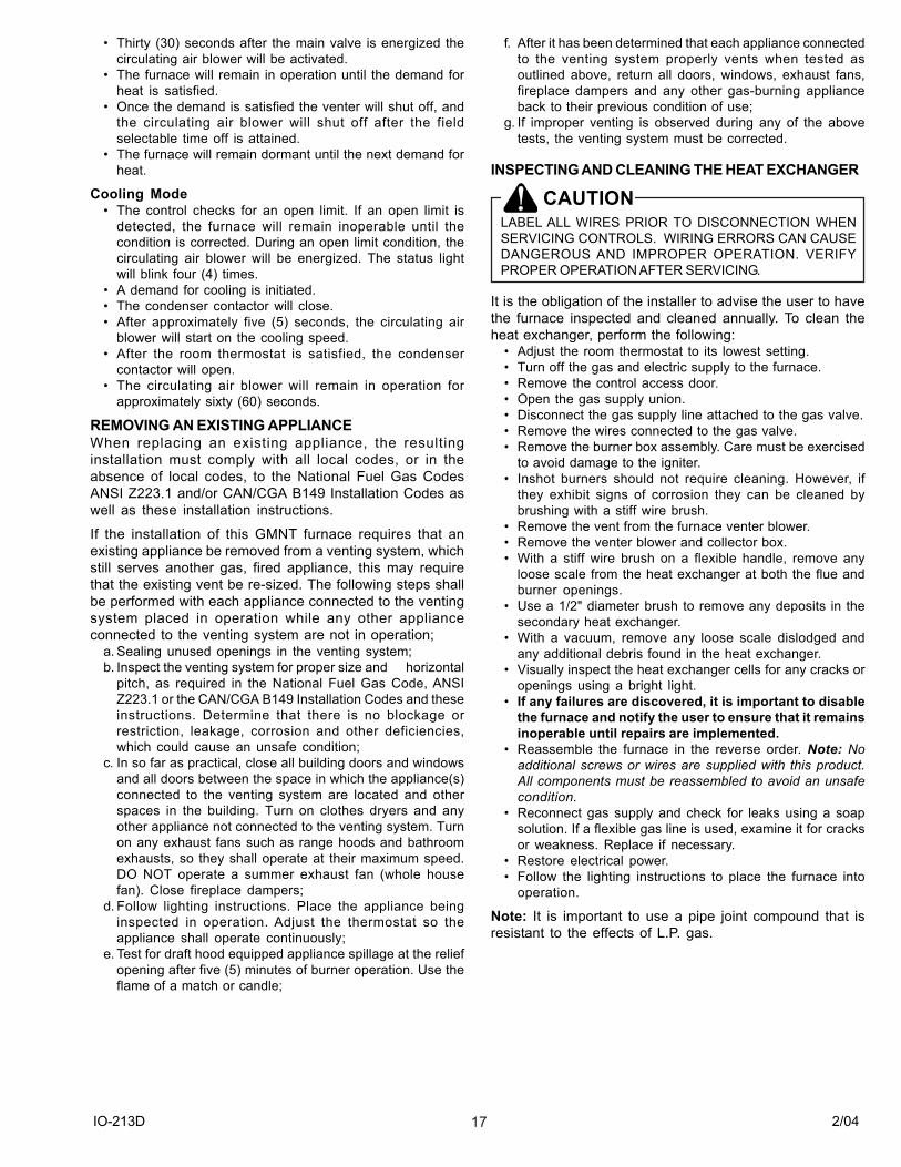
INSPECTING AND CLEANING THE HEAT EXCHANGER
CAUTIONLABEL ALL WIRES PRIOR TO DISCONNECTION WHENSERVICING CONTROLS. WIRING ERRORS CAN CAUSEDANGEROUS AND IMPROPER OPERATION. VERIFYPROPER OPERATION AFTER SERVICING.
It is the obligation of the installer to advise the user to havethe furnace inspected and cleaned annually. To clean theheat exchanger, perform the following:
� Adjust the room thermostat to its lowest setting.� Turn off the gas and electric supply to the furnace.� Remove the control access door.� Open the gas supply union.� Disconnect the gas supply line attached to the gas valve.� Remove the wires connected to the gas valve.� Remove the burner box assembly. Care must be exercised
to avoid damage to the igniter.� Inshot burners should not require cleaning. However, if
they exhibit signs of corrosion they can be cleaned bybrushing with a stiff wire brush.
� Remove the vent from the furnace venter blower.� Remove the venter blower and collector box.� With a stiff wire brush on a flexible handle, remove any
loose scale from the heat exchanger at both the flue andburner openings.
� Use a 1/2" diameter brush to remove any deposits in thesecondary heat exchanger.
� With a vacuum, remove any loose scale dislodged andany additional debris found in the heat exchanger.
� Visually inspect the heat exchanger cells for any cracks oropenings using a bright light.
� If any failures are discovered, it is important to disablethe furnace and notify the user to ensure that it remainsinoperable until repairs are implemented.
� Reassemble the furnace in the reverse order. Note: Noadditional screws or wires are supplied with this product.All components must be reassembled to avoid an unsafecondition.
� Reconnect gas supply and check for leaks using a soapsolution. If a flexible gas line is used, examine it for cracksor weakness. Replace if necessary.
� Restore electrical power.� Follow the lighting instructions to place the furnace into
operation.
Note: It is important to use a pipe joint compound that isresistant to the effects of L.P. gas.
IO-213D 2/0418
LIGHTING DIAGRAM
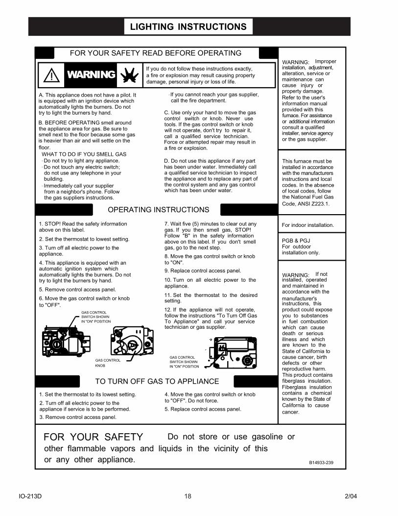
LIGHTING INSTRUCTIONS
installed, operatedautomatically lights the burners. Do not try to light the burners by hand. 10. Turn on all electric power to the
TO TURN OFF GAS TO APPLIANCE
other flammable vapors and liquids in the vicinity of this Do not store or use gasoline or
4. Move the gas control switch or knob
follow the instructions "To Turn Off Gas
to "OFF". Do not force.5. Replace control access panel.
To Appliance" and call your service
12. If the appliance will not operate,
11. Set the thermostat to the desired
technician or gas supplier.
FOR YOUR SAFETY
or any other appliance.
GAS CONTROLGAS CONTROL
3. Remove control access panel.
1. Set the thermostat to its lowest setting.
appliance if service is to be performed.2. Turn off all electric power to the
KNOBSWITCH SHOWN IN "ON" POSITION
6. Move the gas control switch or knob5. Remove control access panel.
SWITCH SHOWN IN "ON" POSITION
GAS CONTROL
to "OFF".
ON
OFF
setting.
appliance.
B14933-239
cause cancer, birthdefects or other
known by the State of
cancer.California to cause
reproductive harm.This product contains
Fiberglass insulationcontains a chemical
fiberglass insulation.
in fuel combustionyou to substances
death or seriouswhich can cause
State of California toare known to theillness and which
accordance with theand maintained in
instructions, thisproduct could expose
manufacturer's
call a qualified service technician. will not operate, don't try to repair it,
gas. If you then smell gas, STOP!
gas, go to the next step.8. Move the gas control switch or knob
above on this label. If you don't smellFollow "B" in the safety information
7. Wait five (5) minutes to clear out any
the control system and any gas controlthe appliance and to replace any part ofa qualified service technician to inspect has been under water. Immediately callD. Do not use this appliance if any part
tools. If the gas control switch or knobcontrol switch or knob. Never useC. Use only your hand to move the gas
which has been under water.
If you do not follow these instructions exactly, a fire or explosion may result causing property
If you cannot reach your gas supplier,
damage, personal injury or loss of life.
call the fire department.
FOR YOUR SAFETY READ BEFORE OPERATING
Force or attempted repair may result in
9. Replace control access panel.
try to light the burners by hand.
the gas suppliers instructions.
OPERATING INSTRUCTIONS
1. STOP! Read the safety information
2. Set the thermostat to lowest setting.3. Turn off all electric power to the
4. This appliance is equipped with an automatic ignition system which
appliance.
above on this label.
to "ON".
B. BEFORE OPERATING smell aroundthe appliance area for gas. Be sure to smell next to the floor because some gasis heavier than air and will settle on the
do not use any telephone in yourDo not touch any electric switch;Do not try to light any appliance.
WHAT TO DO IF YOU SMELL GAS
from a neighbor's phone. FollowImmediately call your supplierbuilding.
floor. a fire or explosion.
A. This appliance does not have a pilot. Itis equipped with an ignition device whichautomatically lights the burners. Do not
furnace. For assistance
the National Fuel Gas
installation only.For outdoorPGB & PGJ
WARNING: If not
Code, ANSI Z223.1.
For indoor installation.
installed in accordanceThis furnace must be
of local codes, follow
instructions and localwith the manufacturers
codes. In the absence
consult a qualified
or the gas supplier.installer, service agency
or additional information
alteration, service ormaintenance cancause injury or
Refer to the user'sinformation manualprovided with this
property damage.
installation, adjustment,WARNING: Improper
WARNING
IO-213D 2/0419
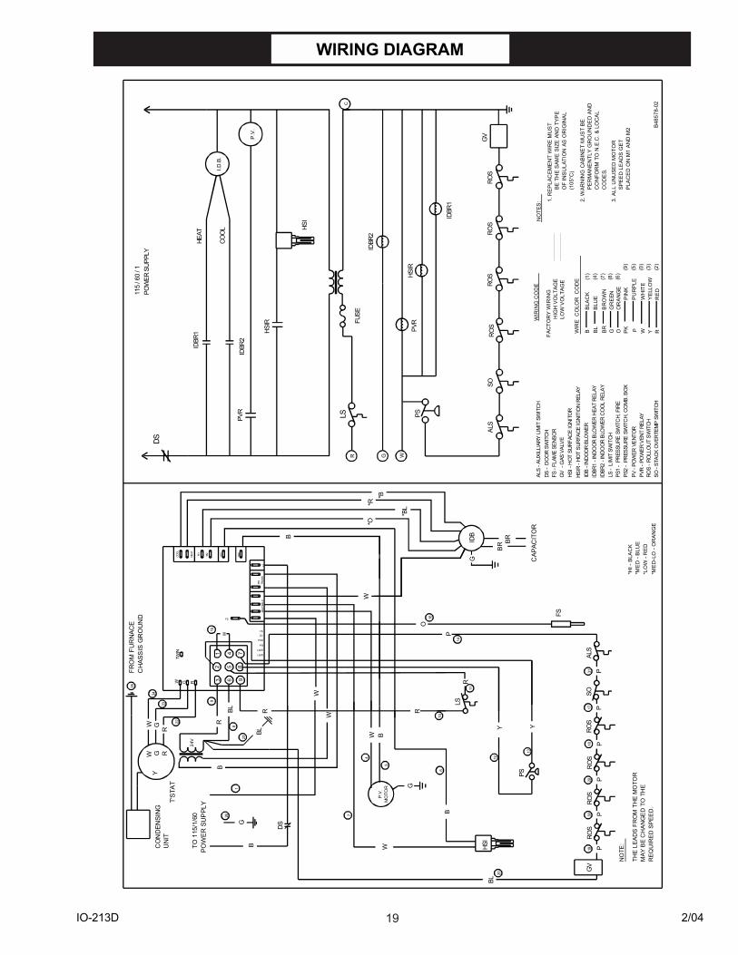
WIRING DIAGRAM
12
3
45
6
78
9
POW
ER S
UP
PLY
TO 1
15/1
/60
24V
B
BP
.V.
MO
TOR G
W
G
BR BR
WIR
E C
OLO
R C
OD
E
B BL
BR
G OO
RA
NG
EG
RE
ENB
RO
WN
BLU
EB
LAC
K
PIN
KP
UR
PLE
WH
ITE
YE
LLO
WR
ED
RYWPK
NO
TE:
THE
LEA
DS
FR
OM
TH
E M
OTO
RM
AY B
E C
HAN
GE
D T
O T
HE
REQ
UIR
ED
SPE
ED
.
P.V
.
I.D.B
.
NO
TES
: 1. R
EP
LAC
EM
EN
T W
IRE
MU
ST
BE
TH
E S
AME
SIZ
E A
ND
TY
PE
OF
INS
ULA
TIO
N A
S O
RIG
INA
L(1
05°C
)
CO
DE
S.C
ON
FOR
M T
O N
.E.C
. & L
OC
AL
PE
RM
ANE
NTL
Y G
RO
UN
DE
D A
ND
2. W
ARN
ING
CA
BIN
ET
MU
ST
BE
WIR
ING
CO
DE
FAC
TOR
Y W
IRIN
GH
IGH
VO
LTAG
ELO
W V
OLT
AG
E
BBL
115
/ 60
/ 1
HEAT
COO
L
LSC
R G W
PS
IDB
- IN
DOO
R BL
OW
ER
LS -
LIM
IT S
WIT
CH
DS -
DO
OR
SWIT
CH
PVR
- PO
WER
VEN
T RE
LAY
ROS
- RO
LLO
UT
SWIT
CH
GV
- G
AS V
ALVE
HSI -
HO
T SU
RFAC
E IG
NIT
OR
IDBR
2
IDBR
1 - I
NDO
OR
BLO
WER
HEA
T RE
LAY
PV -
POW
ER V
ENTO
R
FS -
FLAM
E SE
NSO
R
PS
LS
DS
IDB
GV
FS
HSI
SO
W
COO
L
HEAT
M1
M2
HSI
IND
NEU
TRAL
SPR
ITR
AN
S
W G R
L2
W
W
R
LIMIT
PSI
PSO
GVFS
LIMIT
Y
R
R
Y
CAP
ACIT
OR
PPVR
ROS
GV
IDBR
1
IDBR
2PV
R
HSIR
- HO
T SU
RFA
CE IG
NITI
ON
REL
AY
HSI
FUSE
W GR
B
W
R
O
B
P
FS
TWIN
P
BL
PS1
- PR
ESSU
RE S
WIT
CH,
FIR
E
SO -
STAC
K O
VER
TEM
P SW
ITCH
W RGY
CO
ND
ENSI
NG
UN
IT
SO
T'S
TAT
W
G
HSIR
HSIR
POW
ER S
UPPL
Y
P
IDBR
1
BL
RO
SP
FRO
M F
UR
NAC
EC
HAS
SIS
GR
OU
ND
(1)
(4)
(7)
(8)
(6)
(0)
(2)
(3)
(5)
(9)
PS2
- PR
ESSU
RE S
WIT
CH,
CO
MB.
BO
X
IDBR
2 - I
NDO
OR
BLO
WER
CO
OL
RELA
Y
RO
S
ROS
DS
ROS
P
ROS
B48
578-
02
PRO
S
ROS
ALS
ALS
- AUX
ILLI
ARY
LIM
IT S
WIT
CH
ALS
P
3. A
LL U
NU
SED
MO
TOR
SP
EED
LE
AD
S G
ET
PLA
CE
D O
N M
1 A
ND
M2
*ME
D-L
O -
OR
AN
GE
*LO
W -
RE
D
*HI -
BLA
CK
*ME
D -
BLU
E
*BL
*O*B
*R
25
24
23
22
9
81
26 7
5
4
610
11
12
13
29
20
16
17
14
15
21
1819
3031
IO-213D 2/0420
Quality Makes the Difference!
All of our systems are designed and manufactured with the same high quality standardsregardless of size or efficiency. We have designed these units to significantly reduce the mostfrequent causes of product failure. They are simple to service and forgiving to operate. We usequality materials and components. Finally, every unit is run tested before it leaves the factory.That�s why we know. . . There�s No Better Quality.
Visit our web site at www.goodmanmfg.com for information on:
� Goodman products� Warranties� Customer Services� Parts� Contractor Programs and Training� Financing Options
© 2003-2004 Goodman Manufacturing Company, L.P.