Embed Size (px)
Citation preview
User Manual
InstallationOpen Dual-Band Industrial Access-Point / Client / Access-BridgeOpenBAT-Family: BAT-R
Installation BAT-RRelease 15 12/2019
Technical supporthttps://hirschmann-support.belden.com

The naming of copyrighted trademarks in this manual, even when not specially indicated, should not be taken to mean that these names may be considered as free in the sense of the trademark and tradename protection law and hence that they may be freely used by anyone.
© 2019 Hirschmann Automation and Control GmbH
Manuals and software are protected by copyright. All rights reserved. The copying, reproduction, translation, conversion into any electronic medium or machine scannable form is not permitted, either in whole or in part. An exception is the preparation of a backup copy of the software for your own use.
The performance features described here are binding only if they have been expressly agreed when the contract was made. This document was produced by Hirschmann Automation and Control GmbH according to the best of the company's knowledge. Hirschmann reserves the right to change the contents of this document without prior notice. Hirschmann can give no guarantee in respect of the correctness or accuracy of the information in this document.
Hirschmann can accept no responsibility for damages, resulting from the use of the network components or the associated operating software. In addition, we refer to the conditions of use specified in the license contract.
You can get the latest version of this manual on the Internet at the Hirschmann product site (www.hirschmann.com).
Hirschmann Automation and Control GmbHStuttgarter Str. 45-5172654 NeckartenzlingenGermany
04.12.2019Installation BAT-R
Release 15 12/2019
Contents
Safety instructions 6
About this manual 25
Key 26
1 Description 27
1.1 General description 27
1.2 Device name and product code 28
1.3 Device view 32
1.4 Power supply 331.4.1 Supply voltage with the characteristic value C
(24 V DC ... 48 V DC) 341.4.2 Supply voltage with the characteristic value K
(60 V DC ... 250 V DC / 110 V AC ... 230 V AC, 50 Hz ... 60 Hz) 34
1.4.3 Supply voltage with the characteristic value P (Power supply only through PoE) 34
1.4.4 Supply voltage with the characteristic value W (24 V DC) 34
1.5 Ethernet ports 351.5.1 Gigabit combo port 351.5.2 10/100/1000 Mbit/s twisted-pair connection (optional) 361.5.3 Pin assignments 37
1.6 Connections for antennas 38
1.7 Display elements 381.7.1 Meaning of the LEDs 381.7.2 Device state 381.7.3 Port status 39
1.8 Management interfaces 401.8.1 V.24 interface (external management) 401.8.2 USB interface 41
1.9 Signal contact 42
1.10 Reset button 42
Installation BAT-RRelease 15 12/2019 3
2 Installation 43
2.1 Checking the package contents 43
2.2 Installing and grounding the device 432.2.1 Installing the device onto the DIN rail 442.2.2 Mounting on a vertical flat surface 442.2.3 Grounding the device 44
2.3 Installing an SFP transceiver (optional) 45
2.4 Installing the antennas 45
2.5 Connecting the terminal blocks (optional) 462.5.1 Supply voltage with the characteristic value C
(24 V DC ... 48 V DC) 472.5.2 Supply voltage with the characteristic value K
(60 V DC ... 250 V DC / 110 V AC ... 230 V AC, 50 Hz ... 60 Hz) 47
2.5.3 Supply voltage with the characteristic value W (24 V DC) 48
2.5.4 Signal contact 49
2.6 Operating the device 502.6.1 Connecting the power supply through a terminal
block 502.6.2 Connecting the power supply through PoE 50
2.7 Connecting data cables 512.7.1 Gigabit combo port 512.7.2 10/100/1000 Mbit/s twisted-pair connection (optional) 51
3 Making basic settings 52
4 First login (Password change) 53
5 Obtain compliance for operation in the European Union 54
6 Configuring the transmit power 57
7 Maintenance and service 59
8 Disassembly 60
8.1 Removing the device 60
4Installation BAT-R
Release 15 12/2019
8.2 Removing an SFP transceiver (optional) 60
9 Technical data 61
9.1 General technical data 61
9.2 Dimension drawings 63
9.3 Radio technology 65
9.4 Roaming 65
9.5 Receiving sensitivity, transmit power, and data rate of the WLAN module version EWLAN1 (Approvals 2, characteristic value M, V or 9) 669.5.1 IEEE 802.11b 669.5.2 IEEE 802.11g 669.5.3 IEEE 802.11a 669.5.4 IEEE 802.11n 67
9.6 Receiving sensitivity, transmit power, and data rate of the WLAN module version EWLAN2 for high-gain antennas (Approvals 2, characteristic value H) 699.6.1 IEEE 802.11b 699.6.2 IEEE 802.11g 699.6.3 IEEE 802.11a 699.6.4 IEEE 802.11n 70
9.7 EMC and immunity 72
9.8 Network range 73
9.9 Power consumption/power output 74
10 Scope of delivery, order numbers and accessories 75
11 Underlying technical standards 77
A Further support 79
Installation BAT-RRelease 15 12/2019 5
Safety instructions
General safety instructionsYou operate this device with electricity. Improper usage of the device entails the risk of physical injury or significant property damage. The proper and safe operation of this device depends on proper handling during transportation, proper storage and installation, and careful operation and maintenance procedures. Before connecting any cable, read this document, and the safety
instructions and warnings. Operate the device with undamaged components exclusively. The device is free of any service components. In case of a damaged
or malfunctioning device, turn off the supply voltage and return the device to Hirschmann for inspection.
Internal fuses are triggered only in the case of a detected error in the device. In case of damage or malfunction of the device, turn off the supply voltage and return the device to the plant for inspection.
Certified usage Use the product only for the application cases described in the
Hirschmann product information, including this manual. Operate the product only according to the technical specifications.
See “Technical data” on page 61. Connect to the product only components suitable for the requirements
of the specific application case.
Installation site requirementsRestricted access location: The location is outside the operator access area. The location is accessible to the service personnel even when the
device is switched on.
WARNINGUNCONTROLLED MACHINE ACTIONS To avoid uncontrolled machine actions caused by data loss, configure all the data transmission devices individually.Before you start any machine which is controlled via data transmission, be sure to complete the configuration of all data transmission devices. Failure to follow this instruction can result in death, serious injury, or equipment damage.
6Installation BAT-R
Release 15 12/2019
Indoor operator access area: The location is accessible without tools. The person responsible for the area has provided access for the
operator intentionally. The operator knows of the access possibilities, regardless of whether
they need a tool. Applies to device variants featuring supply voltage with characteristic
value K: (60 V DC ... 250 V DC / 110 V AC ... 230 V AC, 50 Hz ... 60 Hz):See “Device name and product code” on page 28.Install this device solely in a switch cabinet or in an operating site with restricted access, to which maintenance staff have exclusive access.
Relevant for Europe:
Install the device in a fire enclosure according to EN 60950-1.In the following exceptional cases, you do not require a fire-protected shell: You are supplying voltage to the device only via PoE. You are supplying only 24 V to the device and are using a fuse.
Regarding the properties of this fuse: See “General technical data” on page 61.
For use in UL 60950-1 conditions:Install the device in a fire enclosure.
Device casingOnly technicians authorized by the manufacturer are permitted to open the casing. Never insert pointed objects (narrow screwdrivers, wires, etc.) into the
device or into the connection terminals for electric conductors. Do not touch the connection terminals.
Keep the ventilation slits free to ensure good air circulation. Mount the device in the vertical position. At ambient air temperatures > 140 °F (+60 °C):
The surfaces of the device housing may become hot. Avoid touching the device while it is operating.
Qualification requirements for personnel Only allow qualified personnel to work on the device.Qualified personnel have the following characteristics: Qualified personnel are properly trained. Training as well as practical
knowledge and experience make up their qualifications. This is the prerequisite for grounding and labeling circuits, devices, and systems in accordance with current standards in safety technology.
Qualified personnel are aware of the dangers that exist in their work.
Installation BAT-RRelease 15 12/2019 7
Qualified personnel are familiar with appropriate measures against these hazards in order to reduce the risk for themselves and others.
Qualified personnel receive training on a regular basis.
National and international safety regulations Verify that the electrical installation meets local or nationally applicable
safety regulations. When installing antennas, observe the regulations of the country in
which you are operating the WLAN device with regard to the general operating permission and the maximum emission levels.
Install and operate this equipment with a minimum distance of 19.7 inches (50 cm) between the antenna and your body.
Grounding the deviceGrounding the device is by means of a separate ground connection on the device. Ground the device before connecting any other cables. Disconnect the grounding only after disconnecting all other cables. The overall shield of a connected shielded twisted pair cable is connected to the grounding connector on the front panel as a conductor.
Lightning protection Refer to the information in the “WLAN Outdoor Guide” on “Lightning
and overvoltage protection”.The manual is available for download on the Internet: https://www.doc.hirschmann.com
Install over voltage protector devices on every outdoor Ethernet cable. Protect antennas installed outside with lightning protection devices (for
example lightning conductors). Take lightning protection measures which mitigate the effects of
lightning strikes. The installation of the device occurs in accordance with valid
standards (such as VDE 0185 and IEC 62305), and in accordance with the lightning protection procedures recognized and proven for the application and the environment.
Requirements for connecting electrical wiresBefore connecting the electrical wires, always verify that the requirements listed are complied with.
8Installation BAT-R
Release 15 12/2019
The following requirements apply without restrictions: The electrical wires are voltage-free. The cables used are permitted for the temperature range of the application case. Relevant for North America:
The power supply cables are suitable for ambient air temperatures of at least 167 °F (75 °C). The power supply cable wires are made of copper.
Table 1: Requirements for connecting electrical wires
Installation BAT-RRelease 15 12/2019 9
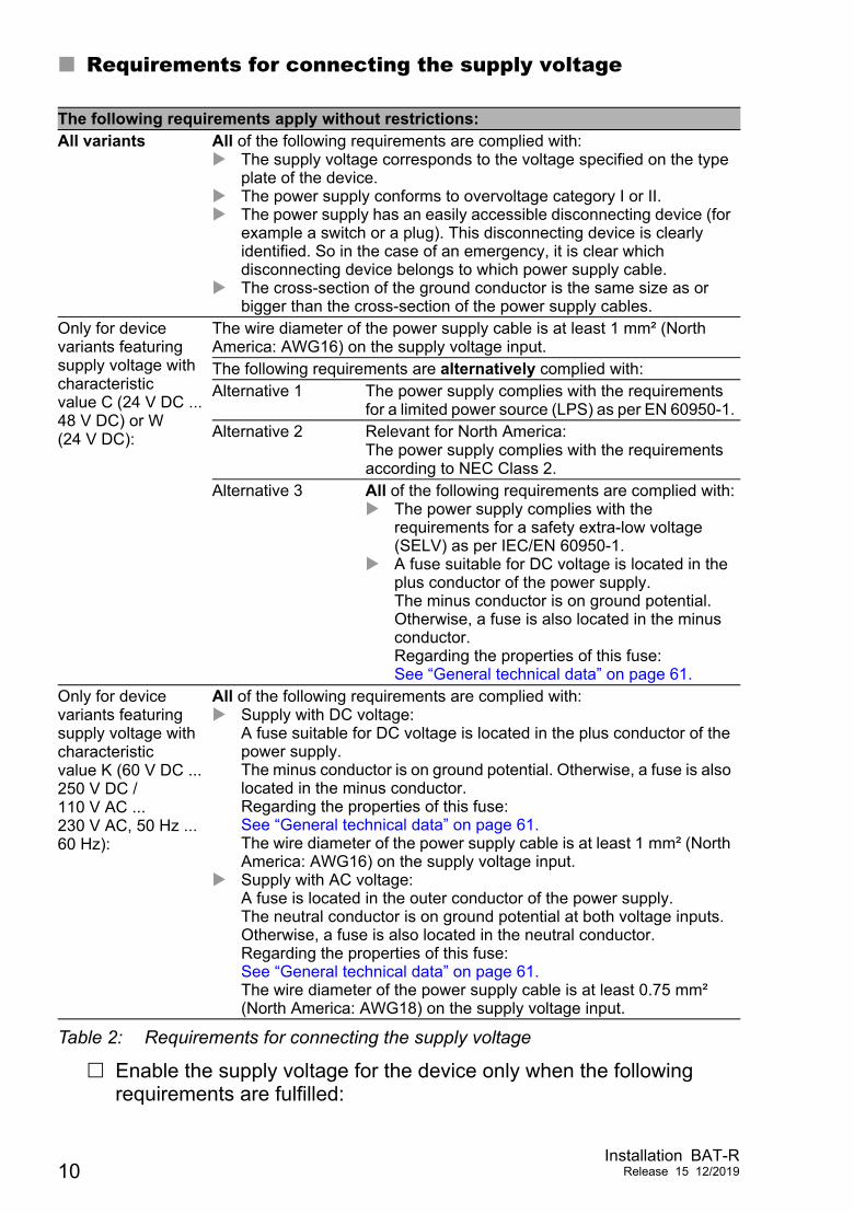
Requirements for connecting the supply voltage
Enable the supply voltage for the device only when the following requirements are fulfilled:
The following requirements apply without restrictions:All variants All of the following requirements are complied with:
The supply voltage corresponds to the voltage specified on the type plate of the device.
The power supply conforms to overvoltage category I or II. The power supply has an easily accessible disconnecting device (for
example a switch or a plug). This disconnecting device is clearly identified. So in the case of an emergency, it is clear which disconnecting device belongs to which power supply cable.
The cross-section of the ground conductor is the same size as or bigger than the cross-section of the power supply cables.
Only for device variants featuring supply voltage with characteristic value C (24 V DC ... 48 V DC) or W (24 V DC):
The wire diameter of the power supply cable is at least 1 mm² (North America: AWG16) on the supply voltage input.The following requirements are alternatively complied with:Alternative 1 The power supply complies with the requirements
for a limited power source (LPS) as per EN 60950-1.Alternative 2 Relevant for North America:
The power supply complies with the requirements according to NEC Class 2.
Alternative 3 All of the following requirements are complied with: The power supply complies with the
requirements for a safety extra-low voltage (SELV) as per IEC/EN 60950-1.
A fuse suitable for DC voltage is located in the plus conductor of the power supply. The minus conductor is on ground potential. Otherwise, a fuse is also located in the minus conductor.Regarding the properties of this fuse: See “General technical data” on page 61.
Only for device variants featuring supply voltage with characteristic value K (60 V DC ... 250 V DC / 110 V AC ... 230 V AC, 50 Hz ... 60 Hz):
All of the following requirements are complied with: Supply with DC voltage:
A fuse suitable for DC voltage is located in the plus conductor of the power supply. The minus conductor is on ground potential. Otherwise, a fuse is also located in the minus conductor.Regarding the properties of this fuse: See “General technical data” on page 61.The wire diameter of the power supply cable is at least 1 mm² (North America: AWG16) on the supply voltage input.
Supply with AC voltage:A fuse is located in the outer conductor of the power supply.The neutral conductor is on ground potential at both voltage inputs. Otherwise, a fuse is also located in the neutral conductor.Regarding the properties of this fuse: See “General technical data” on page 61.The wire diameter of the power supply cable is at least 0.75 mm² (North America: AWG18) on the supply voltage input.
Table 2: Requirements for connecting the supply voltage
10Installation BAT-R
Release 15 12/2019
the housing is closed the terminal blocks are wired correctly the terminal blocks for the power supply are connected
For supply voltage connections with protective conductor connection: First connect the protective conductor before connecting the wires for the supply voltage. If your device comprises a 2nd supply voltage connection of this type: First connect the protective conductor before connecting the wires for the supply voltages.
Installation BAT-RRelease 15 12/2019 11
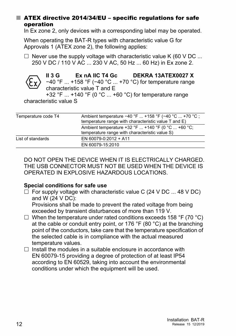
ATEX directive 2014/34/EU – specific regulations for safe operationIn Ex zone 2, only devices with a corresponding label may be operated.
When operating the BAT-R types with characteristic value G for Approvals 1 (ATEX zone 2), the following applies:
Never use the supply voltage with characteristic value K (60 V DC ... 250 V DC / 110 V AC ... 230 V AC, 50 Hz ... 60 Hz) in Ex zone 2.
II 3 G Ex nA IIC T4 Gc DEKRA 13ATEX0027 X−40 °F ... +158 °F (−40 °C ... +70 °C) for temperature range characteristic value T and E +32 °F ... +140 °F (0 °C ... +60 °C) for temperature range
characteristic value S
DO NOT OPEN THE DEVICE WHEN IT IS ELECTRICALLY CHARGED.THE USB CONNECTOR MUST NOT BE USED WHEN THE DEVICE IS OPERATED IN EXPLOSIVE HAZARDOUS LOCATIONS. Special conditions for safe use For supply voltage with characteristic value C (24 V DC ... 48 V DC)
and W (24 V DC): Provisions shall be made to prevent the rated voltage from being exceeded by transient disturbances of more than 119 V.
When the temperature under rated conditions exceeds 158 °F (70 °C) at the cable or conduit entry point, or 176 °F (80 °C) at the branching point of the conductors, take care that the temperature specification of the selected cable is in compliance with the actual measured temperature values.
Install the modules in a suitable enclosure in accordance with EN 60079-15 providing a degree of protection of at least IP54 according to EN 60529, taking into account the environmental conditions under which the equipment will be used.
Temperature code T4 Ambient temperature −40 °F ... +158 °F (−40 °C ... +70 °C ; temperature range with characteristic value T and E)Ambient temperature +32 °F ... +140 °F (0 °C ... +60 °C; temperature range with characteristic value S)
List of standards EN 60079-0:2012 + A11EN 60079-15:2010
12Installation BAT-R
Release 15 12/2019
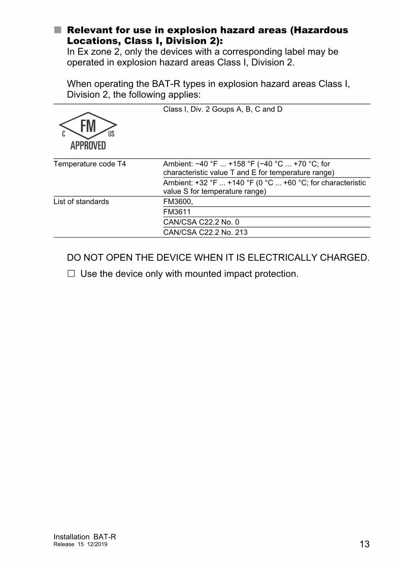
Relevant for use in explosion hazard areas (Hazardous Locations, Class I, Division 2):In Ex zone 2, only the devices with a corresponding label may be operated in explosion hazard areas Class I, Division 2. When operating the BAT-R types in explosion hazard areas Class I, Division 2, the following applies:
DO NOT OPEN THE DEVICE WHEN IT IS ELECTRICALLY CHARGED.
Use the device only with mounted impact protection.
Class I, Div. 2 Goups A, B, C and D
Temperature code T4 Ambient: −40 °F ... +158 °F (−40 °C ... +70 °C; for characteristic value T and E for temperature range)Ambient: +32 °F ... +140 °F (0 °C ... +60 °C; for characteristic value S for temperature range)
List of standards FM3600,FM3611CAN/CSA C22.2 No. 0CAN/CSA C22.2 No. 213
Installation BAT-RRelease 15 12/2019 13
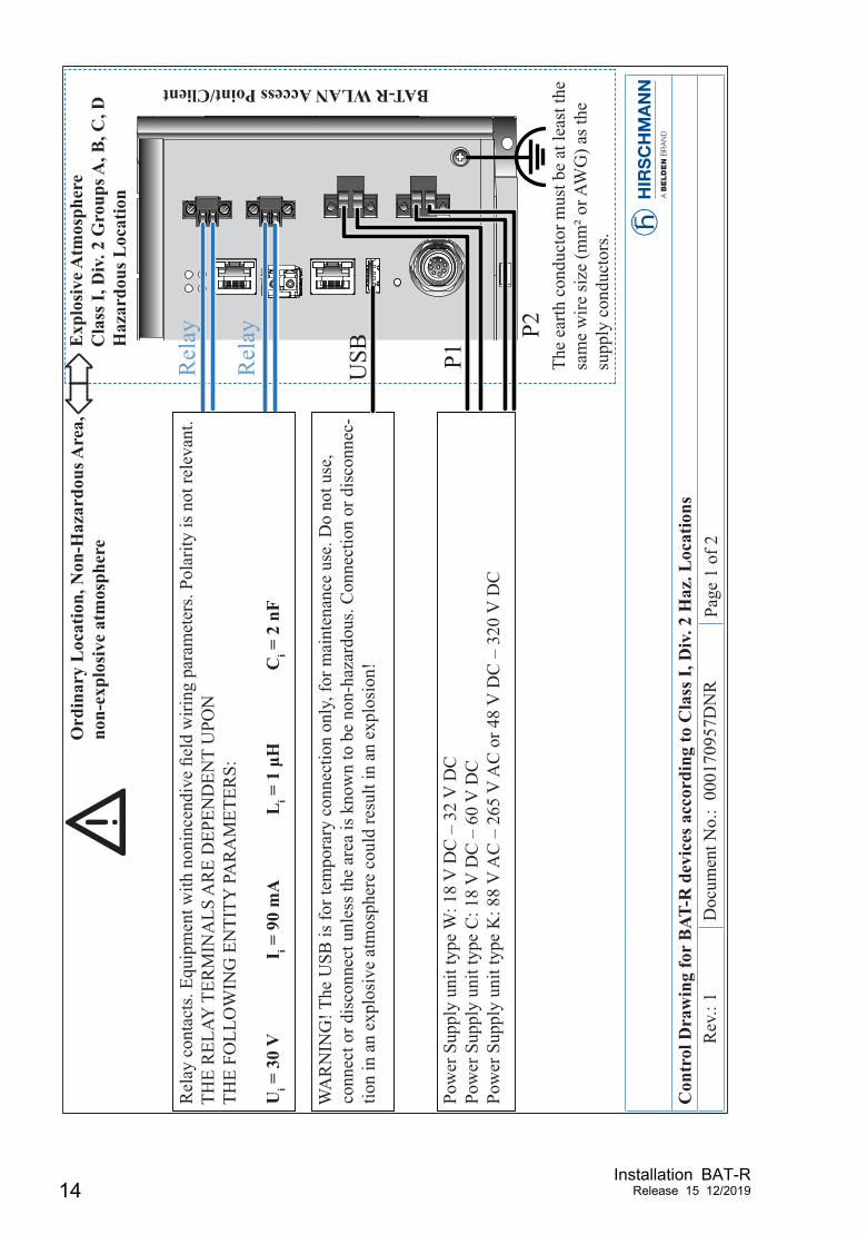
Con
trol
Dra
win
g fo
r B
AT-R
dev
ices
acc
ordi
ng to
Cla
ss I,
Div
. 2 H
az. L
ocat
ions
Rev
.: 1
Doc
umen
t No.
: 00
0170
957D
NR
Page
1 o
f 2
Ord
inar
y L
ocat
ion,
Non
-Haz
ardo
us A
rea,
non-
expl
osiv
e at
mos
pher
eE
xplo
sive
Atm
osph
ere
Cla
ss I,
Div
. 2 G
roup
s A, B
, C, D
H
azar
dous
Loc
atio
n
Pow
er S
uppl
y un
it ty
pe W
: 18
V D
C –
32
V D
CPo
wer
Sup
ply
unit
type
C: 1
8 V
DC
– 6
0 V
DC
Pow
er S
uppl
y un
it ty
pe K
: 88
V A
C –
265
V A
C o
r 48
V D
C –
320
V D
C
The
earth
con
duct
or m
ust b
e at
leas
t the
sa
me
wire
size
(mm
² or A
WG
) as t
he
supp
ly c
ondu
ctor
s.
Rel
ay c
onta
cts.
Equi
pmen
t with
non
ince
ndiv
e e
ld w
iring
par
amet
ers.
Pola
rity
is n
ot re
leva
nt.
THE
REL
AY T
ERM
INA
LS A
RE
DEP
END
ENT
UPO
NTH
E FO
LLO
WIN
G E
NTI
TY P
AR
AM
ETER
S:
Ui =
30
V
I i = 9
0 m
A
Li =
1
H
Ci =
2 n
F
WA
RN
ING
! The
USB
is fo
r tem
pora
ry c
onne
ctio
n on
ly, f
or m
aint
enan
ce u
se. D
o no
t use
, co
nnec
t or d
isco
nnec
t unl
ess t
he a
rea
is k
now
n to
be
non-
haza
rdou
s. C
onne
ctio
n or
dis
conn
ec-
tion
in a
n ex
plos
ive
atm
osph
ere
coul
d re
sult
in a
n ex
plos
ion!
Rel
ay
Rel
ay P2
P1USB
BAT-R WLAN Access Point/Client
14Installation BAT-R
Release 15 12/2019
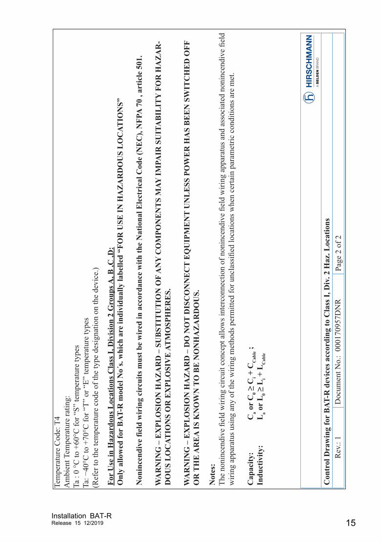
Con
trol
Dra
win
g fo
r B
AT-R
dev
ices
acc
ordi
ng to
Cla
ss I,
Div
. 2 H
az. L
ocat
ions
Rev
.: 1
Doc
umen
t No.
: 00
0170
957D
NR
Page
2 o
f 2
For
Use
in H
azar
dous
Loc
atio
ns C
lass
I, D
ivis
ion
2 G
roup
s A, B
,C ,D
:O
nly
allo
wed
for
BAT
-R m
odel
No´
s. w
hich
are
indi
vidu
ally
labe
lled
“FO
R U
SE IN
HA
ZA
RD
OU
S L
OC
ATIO
NS”
Non
ince
ndiv
e fie
ld w
irin
g ci
rcui
ts m
ust b
e w
ired
in a
ccor
danc
e w
ith th
e N
atio
nal E
lect
rica
l Cod
e (N
EC
), N
FPA
70
, art
icle
501
.
WA
RN
ING
– E
XPL
OSI
ON
HA
ZA
RD
– S
UB
STIT
UT
ION
OF
AN
Y C
OM
PON
EN
TS
MAY
IMPA
IR S
UIT
AB
ILIT
Y F
OR
HA
ZA
R-
DO
US
LO
CAT
ION
S O
R E
XPL
OSI
VE
AT
MO
SPH
ER
ES.
WA
RN
ING
– E
XPL
OSI
ON
HA
ZA
RD
– D
O N
OT
DIS
CO
NN
EC
T E
QU
IPM
EN
T U
NL
ESS
PO
WE
R H
AS
BE
EN
SW
ITC
HE
D O
FF
OR
TH
E A
RE
A IS
KN
OW
N T
O B
E N
ON
HA
ZA
RD
OU
S.
Not
es:
The
noni
ncen
dive
el
d w
iring
circ
uit c
once
pt a
llow
s int
erco
nnec
tion
of n
onin
cend
ive
eld
wiri
ng a
ppar
atus
and
ass
ocia
ted
noni
ncen
dive
el
d w
iring
app
arat
us u
sing
any
of t
he w
iring
met
hods
per
mitt
ed fo
r unc
lass
i ed
loca
tions
whe
n ce
rtain
par
amet
ric c
ondi
tions
are
met
.
Cap
acity
: C
a or
C0
Ci +
CC
able ;
Indu
ctiv
ity:
La o
r L
0 L
i + L
Cab
le
Tem
pera
ture
Cod
e: T
4A
mbi
ent T
empe
ratu
re ra
ting:
Ta :
0 °C
to +
60°C
for “
S” te
mpe
ratu
re ty
pes
Ta:
40°C
to +
70°C
for “
T” o
r “E”
tem
pera
ture
type
s(R
efer
to th
e te
mpe
ratu
re c
ode
of th
e ty
pe d
esig
natio
n on
the
devi
ce.)
Installation BAT-RRelease 15 12/2019 15
E markingThe labeled devices comply with the regulations contained in the following European directive(s): Regulation No. 10 of the Economic Commission for Europe of the United Nations (UN/ECE): Devices with an approval are labeled with the E type approval mark. The optical transceivers M-SFP-SX/LC-EEC and M-SFP-LX/LC-EEC can be used (relevant for devices with approval characteristic value M). Devices featuring supply voltage with characteristic value C are not specified for operation during the motor start phase.
CE markingThe labeled devices comply with the regulations contained in the following European directive(s):
2011/65/EU and 2015/863/EU (RoHS)Directive of the European Parliament and of the Council on the restriction of the use of certain hazardous substances in electrical and electronic equipment.
2014/53/EU (RED)Directive of the European Parliament and of the council on the harmonization of the laws of the Member States relating to the making available on the market of radio equipment.
This product may be operated in all EU (European Union) countries under the condition that it has been configured correctly.
In accordance with the above-named EU directive(s), the EU conformity declaration will be available to the relevant authorities at the following address:
Hirschmann Automation and Control GmbHStuttgarter Str. 45-5172654 NeckartenzlingenGermany
The product can be used in residential areas (residential, commercial and light-industrial environments) and in industrial areas.
16Installation BAT-R
Release 15 12/2019
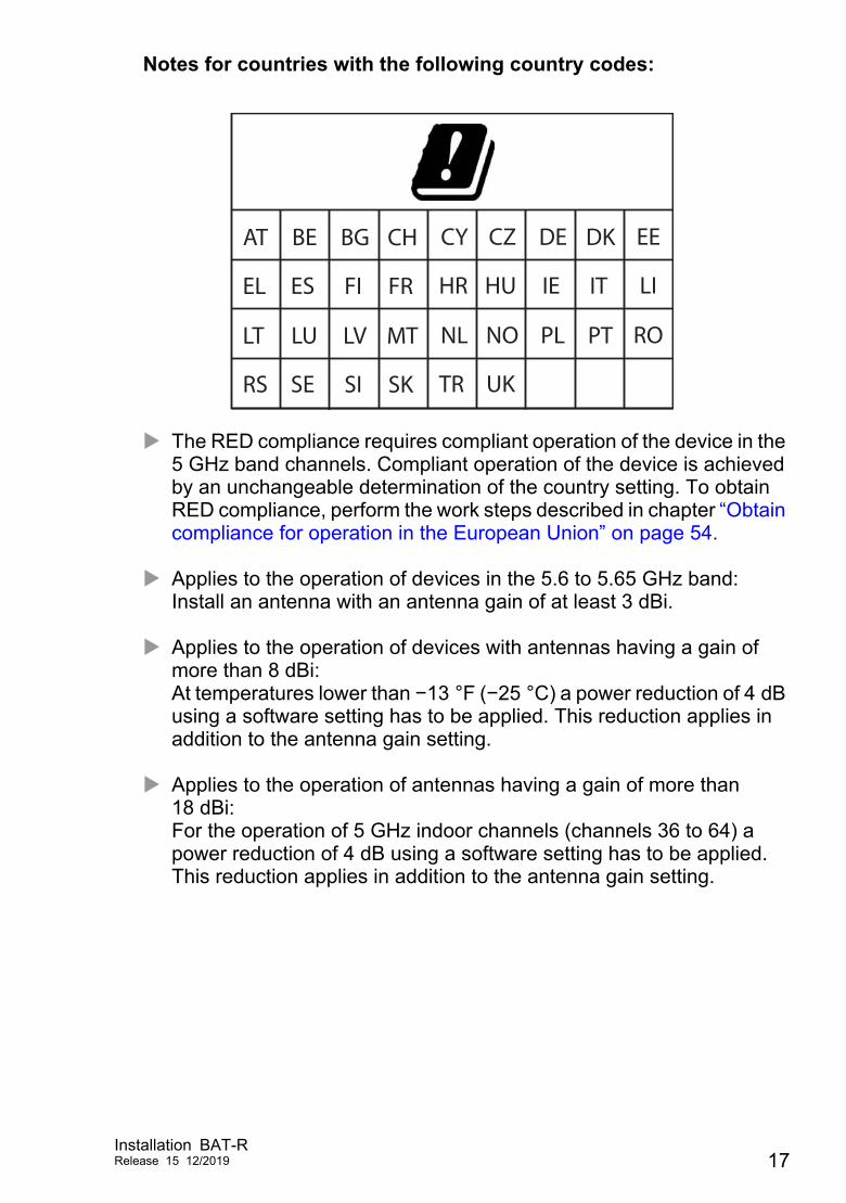
Notes for countries with the following country codes:
The RED compliance requires compliant operation of the device in the 5 GHz band channels. Compliant operation of the device is achieved by an unchangeable determination of the country setting. To obtain RED compliance, perform the work steps described in chapter “Obtain compliance for operation in the European Union” on page 54.
Applies to the operation of devices in the 5.6 to 5.65 GHz band:Install an antenna with an antenna gain of at least 3 dBi.
Applies to the operation of devices with antennas having a gain of more than 8 dBi:At temperatures lower than −13 °F (−25 °C) a power reduction of 4 dB using a software setting has to be applied. This reduction applies in addition to the antenna gain setting.
Applies to the operation of antennas having a gain of more than 18 dBi:For the operation of 5 GHz indoor channels (channels 36 to 64) a power reduction of 4 dB using a software setting has to be applied. This reduction applies in addition to the antenna gain setting.
AT BE BG CH CY CZ DE DK EE
EL ES FI FR HR HU IE IT LI
LT LU LV MT NL NO PL PT RO
RS SE SI SK TR UK
Installation BAT-RRelease 15 12/2019 17
Applies to the operation of the BAT-ANT-N-14G-IP23 antenna:In addition to the antenna cable supplied, the use of the BAT-CLB-2 N m-f antenna is required.See “Accessories” on page 76.
Applies exclusively to BAT-R device variants featuring Approvals 2 with characteristic value V (SRD):The maximum radiated power (EIRP) is 25 mW according to EN 300 440 (Short Range Device).
18Installation BAT-R
Release 15 12/2019
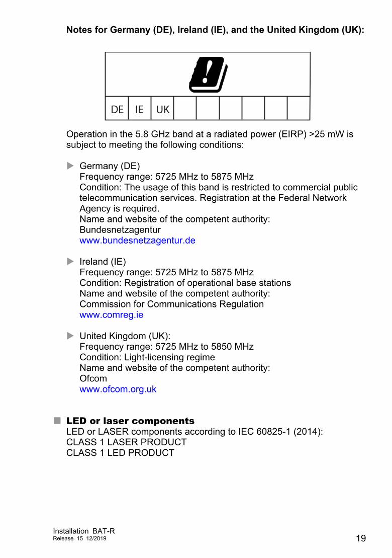
Notes for Germany (DE), Ireland (IE), and the United Kingdom (UK):
Operation in the 5.8 GHz band at a radiated power (EIRP) >25 mW is subject to meeting the following conditions: Germany (DE)
Frequency range: 5725 MHz to 5875 MHzCondition: The usage of this band is restricted to commercial public telecommunication services. Registration at the Federal Network Agency is required. Name and website of the competent authority:Bundesnetzagenturwww.bundesnetzagentur.de
Ireland (IE)Frequency range: 5725 MHz to 5875 MHzCondition: Registration of operational base stationsName and website of the competent authority:Commission for Communications Regulationwww.comreg.ie
United Kingdom (UK):Frequency range: 5725 MHz to 5850 MHzCondition: Light-licensing regimeName and website of the competent authority:Ofcomwww.ofcom.org.uk
LED or laser componentsLED or LASER components according to IEC 60825-1 (2014):CLASS 1 LASER PRODUCTCLASS 1 LED PRODUCT
DE IE UK
Installation BAT-RRelease 15 12/2019 19
FCC note Supplier's Declaration of Conformity47 CFR § 2.1077 Compliance Information BAT-R U.S. Contact InformationBelden – St. Louis1 N. Brentwood Blvd. 15th FloorSt. Louis, Missouri 63105, United States Phone: 314.854.8000 This device complies with part 15 of the FCC rules. Operation is subject to the following two conditions: This device may not cause harmful interference, and This device must accept any interference received, including
interference that may cause undesired operation. This equipment has been tested and found to comply with the limits for a Class B digital device, pursuant to part 15 of the FCC Rules. These limits are designed to provide reasonable protection against harmful interference in a residential installation. This equipment generates, uses and can radiate radio frequency energy and, if not installed and used in accordance with the instructions, may cause harmful interference to radio communications. However, there is no guarantee that interference will not occur in a particular installation. If this equipment does cause harmful interference to radio or television reception, which can be determined by turning the equipment off and on, the user is encouraged to try to correct the interference by one or more of the following measures:
Reposition the receiver antenna or change the angle of the receiver antenna.
Increase the separation between the device and the receiver. Connect the device to a different outlet on a different power supply
cable from that to which the receiver is connected. Consult a specialist retailer or an electronic systems engineer for help.Changes or modifications not expressly approved by the holder of the certificate could void the user’s authority to operate this equipment. EWLAN1 ModuleNote for the use in the USA and in CanadaThe following section applies to BAT-R variants with the characteristic value US (USA/Canada) for country approvals which are labeled as follows:Contains Transmitter Module
20Installation BAT-R
Release 15 12/2019
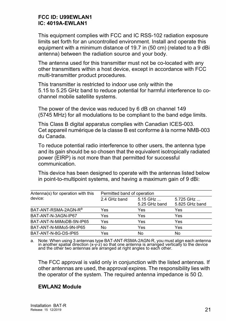
FCC ID: U99EWLAN1IC: 4019A-EWLAN1 This equipment complies with FCC and IC RSS-102 radiation exposure limits set forth for an uncontrolled environment. Install and operate this equipment with a minimum distance of 19.7 in (50 cm) (related to a 9 dBi antenna) between the radiation source and your body.
The antenna used for this transmitter must not be co-located with any other transmitters within a host device, except in accordance with FCC multi-transmitter product procedures.
This transmitter is restricted to indoor use only within the 5.15 to 5.25 GHz band to reduce potential for harmful interference to co-channel mobile satellite systems. The power of the device was reduced by 6 dB on channel 149 (5745 MHz) for all modulations to be compliant to the band edge limits.
This Class B digital apparatus complies with Canadian ICES-003.Cet appareil numérique de la classe B est conforme à la norme NMB-003 du Canada.
To reduce potential radio interference to other users, the antenna type and its gain should be so chosen that the equivalent isotropically radiated power (EIRP) is not more than that permitted for successful communication.
This device has been designed to operate with the antennas listed below in point-to-multipoint systems, and having a maximum gain of 9 dBi:
The FCC approval is valid only in conjunction with the listed antennas. If other antennas are used, the approval expires. The responsibility lies with the operator of the system. The required antenna impedance is 50 Ω. EWLAN2 Module
Antenna(s) for operation with this device:
Permitted band of operation2.4 GHz band 5.15 GHz ...
5.25 GHz band5.725 GHz ... 5.825 GHz band
BAT-ANT-RSMA-2AGN-Ra
a. Note: When using 3 antennas type BAT-ANT-RSMA-2AGN-R, you must align each antenna in another spatial direction (x-y-z) so that one antenna is arranged vertically to the device and the other two antennas are arranged at right angles to each other.
Yes Yes YesBAT-ANT-N-3AGN-IP67 Yes Yes YesBAT-ANT-N-MiMoDB-5N-IP65 Yes Yes YesBAT-ANT-N-MiMo5-9N-IP65 No Yes YesBAT-ANT-N-8G-DS-IP65 Yes No No
Installation BAT-RRelease 15 12/2019 21
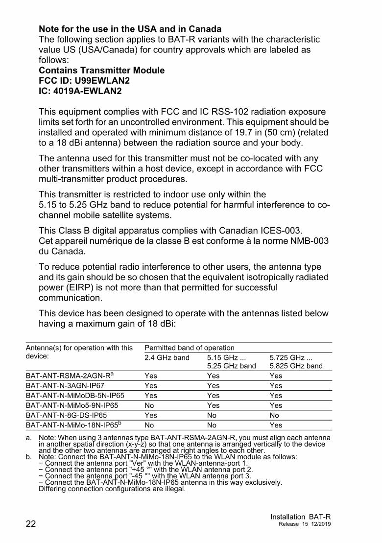
Note for the use in the USA and in CanadaThe following section applies to BAT-R variants with the characteristic value US (USA/Canada) for country approvals which are labeled as follows:Contains Transmitter ModuleFCC ID: U99EWLAN2IC: 4019A-EWLAN2 This equipment complies with FCC and IC RSS-102 radiation exposure limits set forth for an uncontrolled environment. This equipment should be installed and operated with minimum distance of 19.7 in (50 cm) (related to a 18 dBi antenna) between the radiation source and your body.
The antenna used for this transmitter must not be co-located with any other transmitters within a host device, except in accordance with FCC multi-transmitter product procedures.
This transmitter is restricted to indoor use only within the 5.15 to 5.25 GHz band to reduce potential for harmful interference to co-channel mobile satellite systems.
This Class B digital apparatus complies with Canadian ICES-003.Cet appareil numérique de la classe B est conforme à la norme NMB-003 du Canada.
To reduce potential radio interference to other users, the antenna type and its gain should be so chosen that the equivalent isotropically radiated power (EIRP) is not more than that permitted for successful communication.
This device has been designed to operate with the antennas listed below having a maximum gain of 18 dBi:
Antenna(s) for operation with this device:
Permitted band of operation2.4 GHz band 5.15 GHz ...
5.25 GHz band5.725 GHz ... 5.825 GHz band
BAT-ANT-RSMA-2AGN-Ra
a. Note: When using 3 antennas type BAT-ANT-RSMA-2AGN-R, you must align each antenna in another spatial direction (x-y-z) so that one antenna is arranged vertically to the device and the other two antennas are arranged at right angles to each other.
Yes Yes YesBAT-ANT-N-3AGN-IP67 Yes Yes YesBAT-ANT-N-MiMoDB-5N-IP65 Yes Yes YesBAT-ANT-N-MiMo5-9N-IP65 No Yes YesBAT-ANT-N-8G-DS-IP65 Yes No NoBAT-ANT-N-MiMo-18N-IP65b
b. Note: Connect the BAT-ANT-N-MiMo-18N-IP65 to the WLAN module as follows:− Connect the antenna port "Ver" with the WLAN-antenna-port 1.− Connect the antenna port "+45 °" with the WLAN antenna port 2.− Connect the antenna port "-45 °" with the WLAN antenna port 3.− Connect the BAT-ANT-N-MiMo-18N-IP65 antenna in this way exclusively.Differing connection configurations are illegal.
No No Yes
22Installation BAT-R
Release 15 12/2019
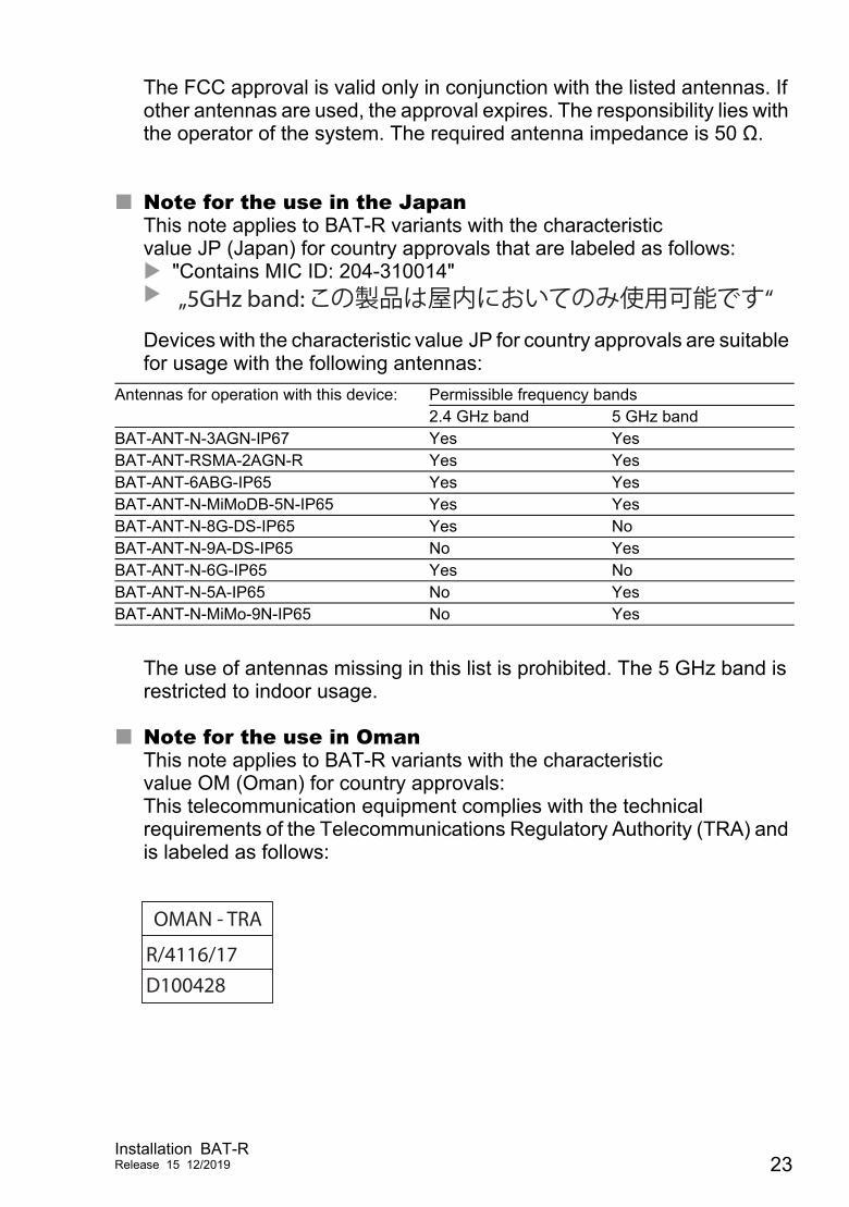
The FCC approval is valid only in conjunction with the listed antennas. If other antennas are used, the approval expires. The responsibility lies with the operator of the system. The required antenna impedance is 50 Ω.
Note for the use in the JapanThis note applies to BAT-R variants with the characteristic value JP (Japan) for country approvals that are labeled as follows: "Contains MIC ID: 204-310014" Devices with the characteristic value JP for country approvals are suitable for usage with the following antennas:
The use of antennas missing in this list is prohibited. The 5 GHz band is restricted to indoor usage.
Note for the use in OmanThis note applies to BAT-R variants with the characteristic value OM (Oman) for country approvals:This telecommunication equipment complies with the technical requirements of the Telecommunications Regulatory Authority (TRA) and is labeled as follows:
Antennas for operation with this device: Permissible frequency bands2.4 GHz band 5 GHz band
BAT-ANT-N-3AGN-IP67 Yes YesBAT-ANT-RSMA-2AGN-R Yes YesBAT-ANT-6ABG-IP65 Yes YesBAT-ANT-N-MiMoDB-5N-IP65 Yes YesBAT-ANT-N-8G-DS-IP65 Yes NoBAT-ANT-N-9A-DS-IP65 No YesBAT-ANT-N-6G-IP65 Yes NoBAT-ANT-N-5A-IP65 No YesBAT-ANT-N-MiMo-9N-IP65 No Yes
„5GHz band: この製品は屋内においてのみ使用可能です“
OMAN - TRA
R/4116/17D100428
Installation BAT-RRelease 15 12/2019 23
Recycling noteAfter usage, this device must be disposed of properly as electronic waste, in accordance with the current disposal regulations of your county, state, and country.
24Installation BAT-R
Release 15 12/2019
About this manual
The “Installation” user manual contains a device description, safety instructions, a description of the display, and the other information that you need to install the device.
Documentation mentioned in the “User Manual Installation” that is not supplied with your device as a printout can be found as PDF files for downloading on the Internet at: https://www.doc.hirschmann.com
Installation BAT-RRelease 15 12/2019 25
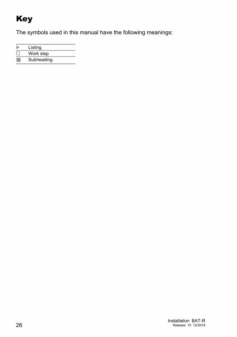
KeyThe symbols used in this manual have the following meanings:
Listing Work step
Subheading
26Installation BAT-R
Release 15 12/2019
1 Description
1.1 General descriptionThe devices allow you to set up WLANs (Wireless Local Area Networks) in a local network. In contrast to a conventional network connection through copper cables and fiber optic cables, some of the communication is performed by means of a radio link. The devices allow you to install a new LAN or expand an existing LAN. Thanks to their high level of flexibility, the OpenBAT device is suitable for a wide range of applications. Anywhere that high bandwidths, stable operation and network security is required, WLAN with these devices provides the ideal solution. The devices are dual-band industrial high-performance wireless LAN access points or clients complying with IEEE 802.11a/b/g/h/n. They provide a high radio output with a bandwidth of up to 450 Mbit/s. The devices support MIMO (Multiple Input Multiple Output) and Multipath. The bandwidth is increased by using the multipath transmission by means of reflections. Each WLAN module has 3 antennas for sending and receiving, to ensure stable network coverage with few shadow areas.
You can choose from between a wide range of variants. You have the option to set up your device individually based on different criteria: Access point or client Number of WLAN modules Number of ports Supply voltage range Configuration (with or without equipment package) Software options Temperature range Approvals The device is designed for the special requirements of industrial automation. The device meets the relevant industry standards, provides very high operational reliability, even under extreme conditions, and also long-term reliability and flexibility.The device works without a fan.
The following installation options are available: Mounting on the DIN rail Mounting on a vertical flat surface
Installation BAT-RRelease 15 12/2019 27

You have the option of choosing various media to connect to the end devices and other network components: Twisted pair cable Multimode F/O Singlemode F/O
There are convenient options for managing the device. Manage your devices via: Web browser SSH Telnet HiDiscovery (software for putting the device into operation) Management software (for example Industrial HiVision, LANconfig/
LANmonitor)The Network Management Software Industrial HiVision provides you with options for smooth configuration and monitoring. You find further information on the Internet at the Hirschmann product pages:http://www.hirschmann.com/en/QR/INET-Industrial-HiVision
V.24 interface (locally on the device)
The device provides you with a large range of functions, which the manuals for the operating software inform you about. You can download these manuals as PDF files from the Internet on the Hirschmann product pages (http://www.doc.hirschmann.com). The Hirschmann network components help you ensure continuous communication across all levels of the company.
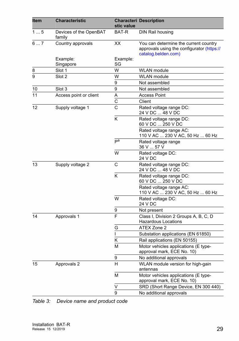
1.2 Device name and product codeThe device name corresponds to the product code. The product code is made up of characteristics with defined positions. The characteristic values stand for specific product properties.You have numerous options of combining the device characteristics. You can determine the possible combinations using the configurator which is available in the Belden Online Catalog https://catalog.belden.com on the web page of the device.
28Installation BAT-R
Release 15 12/2019
Item Characteristic Characteristic value
Description
1 ... 5 Devices of the OpenBAT family
BAT-R DIN Rail housing
6 ... 7 Country approvals Example:Singapore
XX Example:SG
You can determine the current country approvals using the configurator (https://catalog.belden.com)
8 Slot 1 W WLAN module9 Slot 2 W WLAN module
9 Not assembled10 Slot 3 9 Not assembled11 Access point or client A Access Point
C Client12 Supply voltage 1 C Rated voltage range DC:
24 V DC ... 48 V DCK Rated voltage range DC:
60 V DC ... 250 V DCRated voltage range AC:110 V AC ... 230 V AC, 50 Hz ... 60 Hz
Pa Rated voltage range36 V ... 57 V
W Rated voltage DC:24 V DC
13 Supply voltage 2 C Rated voltage range DC:24 V DC ... 48 V DC
K Rated voltage range DC:60 V DC ... 250 V DCRated voltage range AC:110 V AC ... 230 V AC, 50 Hz ... 60 Hz
W Rated voltage DC:24 V DC
9 Not present14 Approvals 1 F Class I, Division 2 Groups A, B, C, D
Hazardous LocationsG ATEX Zone 2I Substation applications (EN 61850)K Rail applications (EN 50155)M Motor vehicles applications (E type-
approval mark, ECE No. 10)9 No additional approvals
15 Approvals 2 H WLAN module version for high-gain antennas
M Motor vehicles applications (E type-approval mark, ECE No. 10)
V SRD (Short Range Device, EN 300 440)9 No additional approvals
Table 3: Device name and product code
Installation BAT-RRelease 15 12/2019 29
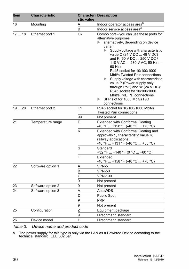
16 Mounting A Indoor operator access areab
B Indoor service access areac
17 ... 18 Ethernet port 1 O7 Combo port – you can use these ports for alternative purposes: alternatively, depending on device
variant Supply voltage with characteristic
value C (24 V DC ... 48 V DC) and K (60 V DC ... 250 V DC / 110 V AC ... 230 V AC, 50 Hz ... 60 Hz):RJ45 socket for 10/100/1000 Mbit/s Twisted Pair connections
Supply voltage with characteristic value P (Power supply only through PoE) and W (24 V DC):RJ45 socket for 10/100/1000 Mbit/s PoE PD connections
SFP slot for 1000 Mbit/s F/O connections
19 ... 20 Ethernet port 2 T1 RJ45 socket for 10/100/1000 Mbit/s Twisted Pair connections
99 Not present21 Temperature range E Extended with Conformal Coating
-40 °F ... +158 °F (-40 °C ... +70 °C)K Extended with Conformal Coating and
approvals 1, characteristic value K, railway applications:-40 °F ... +131 °F (-40 °C ... +55 °C)
S Standard+32 °F ... +140 °F (0 °C ... +60 °C)
T Extended-40 °F ... +158 °F (-40 °C ... +70 °C)
22 Software option 1 A VPN-5B VPN-50C VPN-1009 Not present
23 Software option 2 9 Not present24 Software option 3 A AutoWDS
D Public SpotP PRP9 Not present
25 Configuration Z Equipment package9 Hirschmann standard
26 Device model H Hirschmann standard
a. The power supply for this type is only via the LAN as a Powered Device according to the technical standard IEEE 802.3af.
Item Characteristic Characteristic value
Description
Table 3: Device name and product code
30Installation BAT-R
Release 15 12/2019
b. Location for which one of the following conditions apply when one operates it correctly:- The area is accessible without tools.- The person responsible for the area has provided access for the operator intentionally.- The operator knows of the access possibilities, regardless of whether they need a tool.
c. Location outside the operator area to which the service personnel has access, even when the device is switched on.
Installation BAT-RRelease 15 12/2019 31
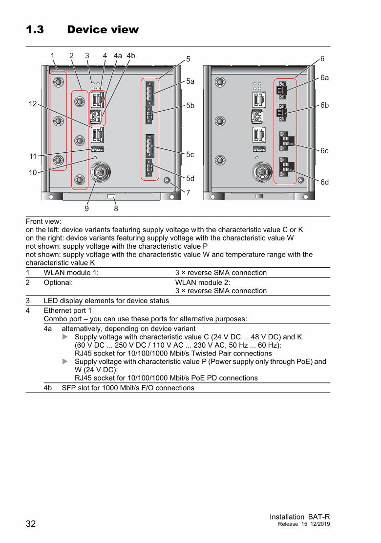
1.3 Device view
Front view:on the left: device variants featuring supply voltage with the characteristic value C or Kon the right: device variants featuring supply voltage with the characteristic value Wnot shown: supply voltage with the characteristic value Pnot shown: supply voltage with the characteristic value W and temperature range with the characteristic value K1 WLAN module 1: 3 × reverse SMA connection2 Optional: WLAN module 2:
3 × reverse SMA connection3 LED display elements for device status4 Ethernet port 1
Combo port – you can use these ports for alternative purposes:4a alternatively, depending on device variant
Supply voltage with characteristic value C (24 V DC ... 48 V DC) and K (60 V DC ... 250 V DC / 110 V AC ... 230 V AC, 50 Hz ... 60 Hz):RJ45 socket for 10/100/1000 Mbit/s Twisted Pair connections
Supply voltage with characteristic value P (Power supply only through PoE) and W (24 V DC):RJ45 socket for 10/100/1000 Mbit/s PoE PD connections
4b SFP slot for 1000 Mbit/s F/O connections
1 2 3 4 4a 4b
5d
5c
5b
5a
7
6
9 8
12
11
10
6a
6b
6c
6d
5 6
32Installation BAT-R
Release 15 12/2019
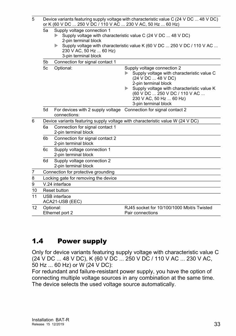
1.4 Power supplyOnly for device variants featuring supply voltage with characteristic value C (24 V DC ... 48 V DC), K (60 V DC ... 250 V DC / 110 V AC ... 230 V AC, 50 Hz ... 60 Hz) or W (24 V DC):For redundant and failure-resistant power supply, you have the option of connecting multiple voltage sources in any combination at the same time. The device selects the used voltage source automatically.
5 Device variants featuring supply voltage with characteristic value C (24 V DC ... 48 V DC) or K (60 V DC ... 250 V DC / 110 V AC ... 230 V AC, 50 Hz ... 60 Hz)5a Supply voltage connection 1
Supply voltage with characteristic value C (24 V DC ... 48 V DC)2-pin terminal block
Supply voltage with characteristic value K (60 V DC ... 250 V DC / 110 V AC ... 230 V AC, 50 Hz ... 60 Hz)3-pin terminal block
5b Connection for signal contact 15c Optional: Supply voltage connection 2
Supply voltage with characteristic value C (24 V DC ... 48 V DC)2-pin terminal block
Supply voltage with characteristic value K (60 V DC ... 250 V DC / 110 V AC ... 230 V AC, 50 Hz ... 60 Hz)3-pin terminal block
5d For devices with 2 supply voltage connections:
Connection for signal contact 2
6 Device variants featuring supply voltage with characteristic value W (24 V DC)6a Connection for signal contact 1
2-pin terminal block6b Connection for signal contact 2
2-pin terminal block6c Supply voltage connection 1
2-pin terminal block6d Supply voltage connection 2
2-pin terminal block7 Connection for protective grounding8 Locking gate for removing the device9 V.24 interface10 Reset button11 USB interface
ACA21-USB (EEC)12 Optional:
Ethernet port 2RJ45 socket for 10/100/1000 Mbit/s Twisted Pair connections
Installation BAT-RRelease 15 12/2019 33
Switching to a redundant voltage source possibly occurs with a short delay. If the active power source is lost and another power source takes over the power supply to the device, the device reboots if necessary to activate the redundant power supply.
1.4.1 Supply voltage with the characteristic value C (24 V DC ... 48 V DC)
A 2-pin terminal block is available to supply the device with power.Further information:“Supply voltage with the characteristic value C (24 V DC ... 48 V DC)” on page 47
1.4.2 Supply voltage with the characteristic value K (60 V DC ... 250 V DC / 110 V AC ... 230 V AC, 50 Hz ... 60 Hz)
For the power supply of the device, a 3-pin terminal block is available.Further information:“Supply voltage with the characteristic value K (60 V DC ... 250 V DC / 110 V AC ... 230 V AC, 50 Hz ... 60 Hz)” on page 47
1.4.3 Supply voltage with the characteristic value P (Power supply only through PoE)
Note: With supply voltage with the characteristic value P (Power supply only through PoE), the signal contact is omitted.
Your device is a PD (powered device). PSE (power sourcing equipment) connected via a twisted pair cable on the PoE PD port serves as the PoE power supply voltage. The PoE power supply means that no separate power supply is required for your device.Further information:“10/100/1000 Mbit/s PoE PD port” on page 51
1.4.4 Supply voltage with the characteristic value W (24 V DC)
You have the following options to supply your device with voltage:
Power supply through a terminal blockA 2-pin terminal block is available to supply the device with power.Further information:“Supply voltage with the characteristic value W (24 V DC)” on page 48
34Installation BAT-R
Release 15 12/2019
Power supply through PoE
Note: For devices with 2 WLAN modules, the option of suppling power via PoE is unavailable.
Your device is a PD (powered device). PSE (power sourcing equipment) connected via a twisted pair cable on the PoE PD port serves as the PoE power supply voltage. The PoE power supply means that no separate power supply is required for your device.Further information:“10/100/1000 Mbit/s PoE PD port” on page 35
1.5 Ethernet portsYou can connect end devices and other segments to the device ports using twisted pair cables or optical fibers (F/O).You find information on pin assignments for making patch cables here:“Pin assignments” on page 37
1.5.1 Gigabit combo portYou have the option of alternatively connecting a twisted pair cable via a RJ45 socket or an optical fiber via a SFP transceiver to a combo port.Only plug a connector or SFP transceiver that you want to use for the data transmission into the socket of the combo port.
10/100/1000 Mbit/s PoE PD portOnly device variants featuring supply voltage with characteristic value P (Power supply only through PoE) or W (24 V DC) have this port.The 10/100/1000 Mbit/s PoE PD port offers you the ability to connect network components according to the IEEE 802.3 10BASE-T/100BASE-TX/1000BASE-T and IEEE 802.3af/at standard.This port supports: Autocrossing (if autonegotiation is activated) Autonegotiation Autopolarity 10 Mbit/s half-duplex mode, 10 Mbit/s full duplex mode 100 Mbit/s half-duplex mode, 100 Mbit/s full duplex mode 1000 Mbit/s full duplexDelivery state: Autonegotiation activatedThe port casing is electrically connected to the front panel.The pin assignment corresponds to MDI-X.
Installation BAT-RRelease 15 12/2019 35
When using 10/100 Mbit/s, the PoE power is supplied via the signal-transmitting wire pair (phantom voltage) or via the free wire pairs (spare pair supply).
10/100/1000 Mbit/s twisted pair portOnly device variants featuring supply voltage with characteristic value C (24 V DC ... 48 V DC) or K (60 V DC ... 250 V DC / 110 V AC ... 230 V AC, 50 Hz ... 60 Hz) have this port.The 10/100/1000 Mbit/s twisted pair port allows you to connect network components according to the IEEE 802.3 10BASE-T/100BASE-TX/1000BASE-T standard.This port supports: Autocrossing (if autonegotiation is activated) Autonegotiation Autopolarity 10 Mbit/s half-duplex mode, 10 Mbit/s full duplex mode 100 Mbit/s half-duplex mode, 100 Mbit/s full duplex mode 1000 Mbit/s full duplexDelivery state: Autonegotiation activatedThe port casing is electrically connected to the front panel.The pin assignment corresponds to MDI-X.
1000 Mbit/s F/O portThe 1000 Mbit/s F/O port offers you the ability to connect network components according to the IEEE 802.3 1000BASE-SX/1000BASE-LX standard.This port supports: Full duplex mode
1.5.2 10/100/1000 Mbit/s twisted-pair connection (optional)See the properties of this port “10/100/1000 Mbit/s twisted pair port” on page 36.
36Installation BAT-R
Release 15 12/2019
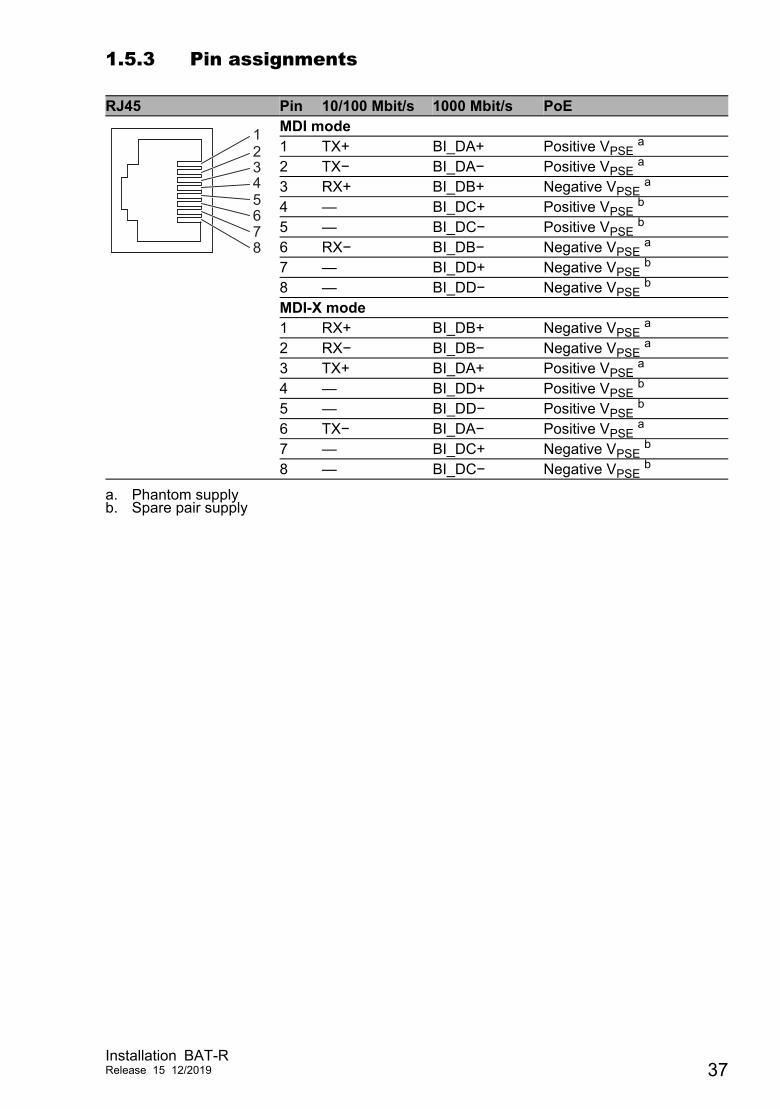
1.5.3 Pin assignments
RJ45 Pin 10/100 Mbit/s 1000 Mbit/s PoEMDI mode1 TX+ BI_DA+ Positive VPSE a
a. Phantom supply
2 TX− BI_DA− Positive VPSE a
3 RX+ BI_DB+ Negative VPSE a
4 — BI_DC+ Positive VPSE b
b. Spare pair supply
5 — BI_DC− Positive VPSE b
6 RX− BI_DB− Negative VPSE a
7 — BI_DD+ Negative VPSE b
8 — BI_DD− Negative VPSE b
MDI-X mode1 RX+ BI_DB+ Negative VPSE a
2 RX− BI_DB− Negative VPSE a
3 TX+ BI_DA+ Positive VPSE a
4 — BI_DD+ Positive VPSE b
5 — BI_DD− Positive VPSE b
6 TX− BI_DA− Positive VPSE a
7 — BI_DC+ Negative VPSE b
8 — BI_DC− Negative VPSE b
12345678
Installation BAT-RRelease 15 12/2019 37
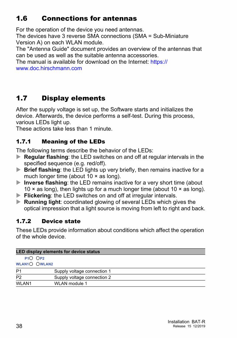
1.6 Connections for antennasFor the operation of the device you need antennas.The devices have 3 reverse SMA connections (SMA = Sub-Miniature Version A) on each WLAN module.The "Antenna Guide" document provides an overview of the antennas that can be used as well as the suitable antenna accessories.The manual is available for download on the Internet: https://www.doc.hirschmann.com
1.7 Display elementsAfter the supply voltage is set up, the Software starts and initializes the device. Afterwards, the device performs a self-test. During this process, various LEDs light up.These actions take less than 1 minute.
1.7.1 Meaning of the LEDsThe following terms describe the behavior of the LEDs: Regular flashing: the LED switches on and off at regular intervals in the
specified sequence (e.g. red/off). Brief flashing: the LED lights up very briefly, then remains inactive for a
much longer time (about 10 × as long). Inverse flashing: the LED remains inactive for a very short time (about
10 × as long), then lights up for a much longer time (about 10 × as long). Flickering: the LED switches on and off at irregular intervals. Running light: coordinated glowing of several LEDs which gives the
optical impression that a light source is moving from left to right and back.
1.7.2 Device stateThese LEDs provide information about conditions which affect the operation of the whole device.
LED display elements for device status
P1 Supply voltage connection 1P2 Supply voltage connection 2WLAN1 WLAN module 1
P1WLAN2P2
WLAN1
38Installation BAT-R
Release 15 12/2019
1.7.3 Port statusThese LEDs provide port-related information.The LEDs are directly located on the ports.
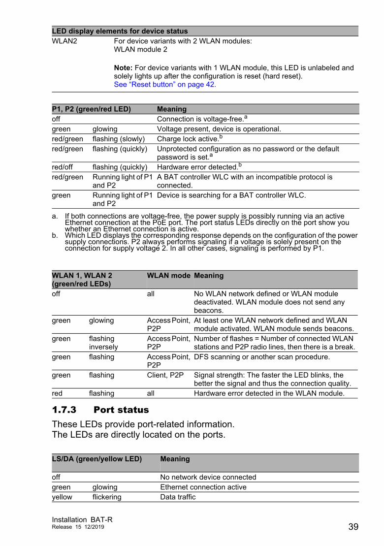
WLAN2 For device variants with 2 WLAN modules:WLAN module 2
Note: For device variants with 1 WLAN module, this LED is unlabeled and solely lights up after the configuration is reset (hard reset).See “Reset button” on page 42.
P1, P2 (green/red LED) Meaningoff Connection is voltage-free.a
a. If both connections are voltage-free, the power supply is possibly running via an active Ethernet connection at the PoE port. The port status LEDs directly on the port show you whether an Ethernet connection is active.
green glowing Voltage present, device is operational.red/green flashing (slowly) Charge lock active.b
b. Which LED displays the corresponding response depends on the configuration of the power supply connections. P2 always performs signaling if a voltage is solely present on the connection for supply voltage 2. In all other cases, signaling is performed by P1.
red/green flashing (quickly) Unprotected configuration as no password or the default password is set.a
red/off flashing (quickly) Hardware error detected.b
red/green Running light of P1 and P2
A BAT controller WLC with an incompatible protocol is connected.
green Running light of P1 and P2
Device is searching for a BAT controller WLC.
WLAN 1, WLAN 2 (green/red LEDs)
WLAN mode Meaning
off all No WLAN network defined or WLAN module deactivated. WLAN module does not send any beacons.
green glowing Access Point, P2P
At least one WLAN network defined and WLAN module activated. WLAN module sends beacons.
green flashing inversely
Access Point, P2P
Number of flashes = Number of connected WLAN stations and P2P radio lines, then there is a break.
green flashing Access Point, P2P
DFS scanning or another scan procedure.
green flashing Client, P2P Signal strength: The faster the LED blinks, the better the signal and thus the connection quality.
red flashing all Hardware error detected in the WLAN module.
LS/DA (green/yellow LED) Meaning
off No network device connectedgreen glowing Ethernet connection activeyellow flickering Data traffic
LED display elements for device status
Installation BAT-RRelease 15 12/2019 39
1.8 Management interfaces
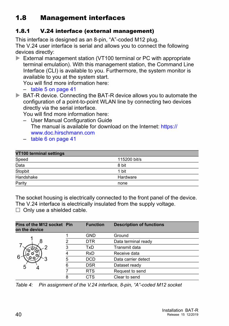
1.8.1 V.24 interface (external management)This interface is designed as an 8-pin, “A”-coded M12 plug.The V.24 user interface is serial and allows you to connect the following devices directly: External management station (VT100 terminal or PC with appropriate
terminal emulation). With this management station, the Command Line Interface (CLI) is available to you. Furthermore, the system monitor is available to you at the system start.You will find more information here:– table 5 on page 41
BAT-R device. Connecting the BAT-R device allows you to automate the configuration of a point-to-point WLAN line by connecting two devices directly via the serial interface.You will find more information here:– User Manual Configuration Guide
The manual is available for download on the Internet: https://www.doc.hirschmann.com
– table 6 on page 41
The socket housing is electrically connected to the front panel of the device. The V.24 interface is electrically insulated from the supply voltage. Only use a shielded cable.
VT100 terminal settingsSpeed 115200 bit/sData 8 bitStopbit 1 bitHandshake HardwareParity none
Pins of the M12 socket on the device
Pin Function Description of functions
1 GND Ground 2 DTR Data terminal ready 3 TxD Transmit data 4 RxD Receive data 5 DCD Data carrier detect 6 DSR Dataset ready 7 RTS Request to send 8 CTS Clear to send
Table 4: Pin assignment of the V.24 interface, 8-pin, “A”-coded M12 socket
82
34
7
6
1
5
40Installation BAT-R
Release 15 12/2019
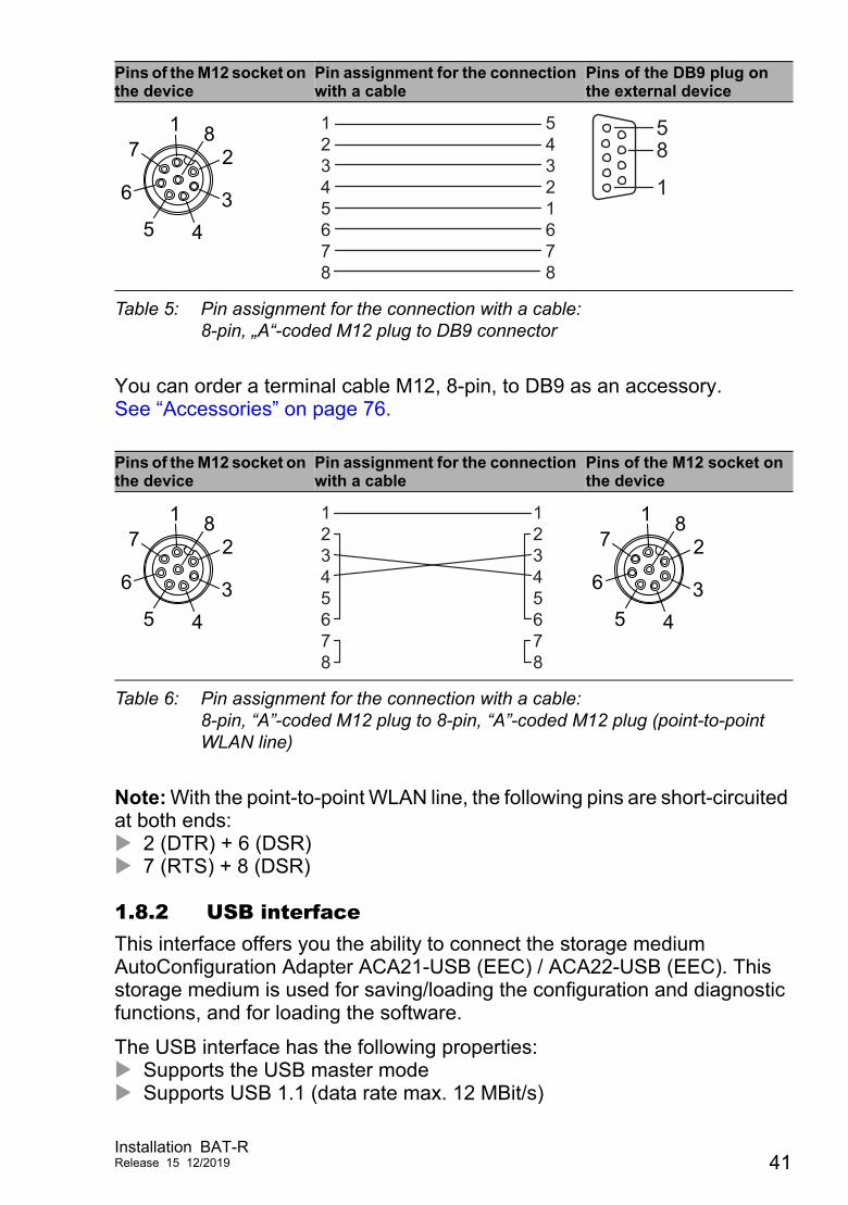
You can order a terminal cable M12, 8-pin, to DB9 as an accessory.See “Accessories” on page 76.
Note: With the point-to-point WLAN line, the following pins are short-circuited at both ends: 2 (DTR) + 6 (DSR) 7 (RTS) + 8 (DSR)
1.8.2 USB interfaceThis interface offers you the ability to connect the storage medium AutoConfiguration Adapter ACA21-USB (EEC) / ACA22-USB (EEC). This storage medium is used for saving/loading the configuration and diagnostic functions, and for loading the software.
The USB interface has the following properties: Supports the USB master mode Supports USB 1.1 (data rate max. 12 MBit/s)
Pins of the M12 socket on the device
Pin assignment for the connection with a cable
Pins of the DB9 plug on the external device
Table 5: Pin assignment for the connection with a cable:8-pin, „A“-coded M12 plug to DB9 connector
Pins of the M12 socket on the device
Pin assignment for the connection with a cable
Pins of the M12 socket on the device
Table 6: Pin assignment for the connection with a cable:8-pin, “A”-coded M12 plug to 8-pin, “A”-coded M12 plug (point-to-point WLAN line)
82
34
7
6
1
5
12345678
54321678
1
85
82
34
7
6
1
5
12345678
12345678
82
34
7
6
1
5
Installation BAT-RRelease 15 12/2019 41
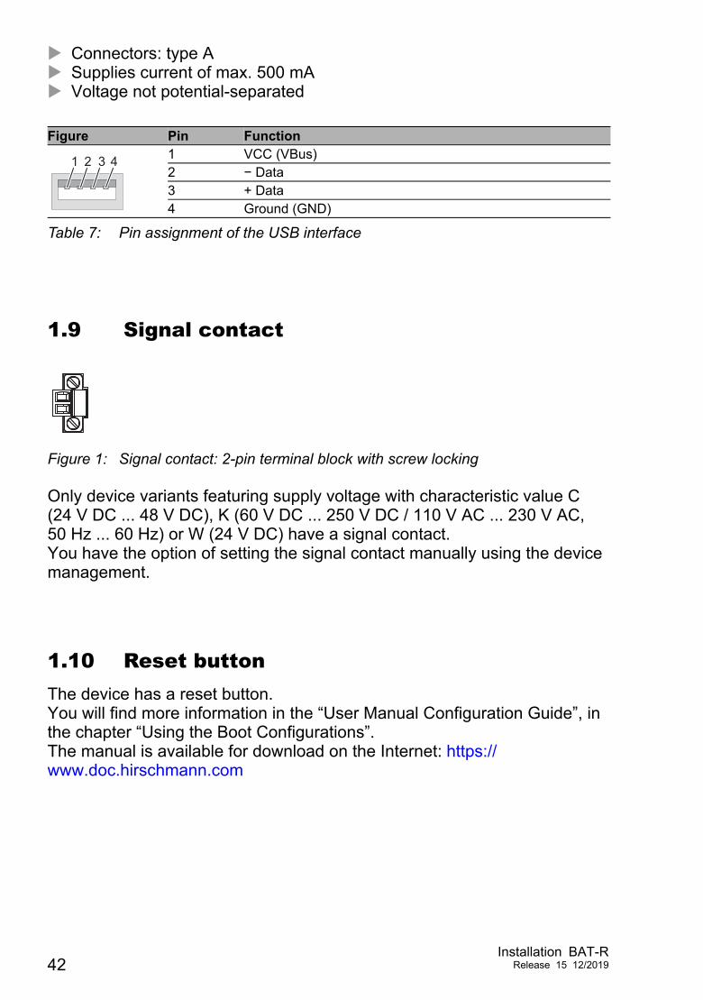
Connectors: type A Supplies current of max. 500 mA Voltage not potential-separated
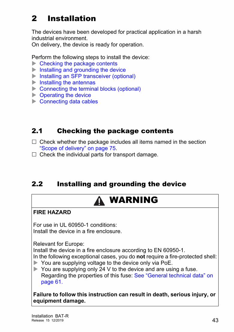
1.9 Signal contact
Figure 1: Signal contact: 2-pin terminal block with screw locking
Only device variants featuring supply voltage with characteristic value C (24 V DC ... 48 V DC), K (60 V DC ... 250 V DC / 110 V AC ... 230 V AC, 50 Hz ... 60 Hz) or W (24 V DC) have a signal contact.You have the option of setting the signal contact manually using the device management.
1.10 Reset buttonThe device has a reset button.You will find more information in the “User Manual Configuration Guide”, in the chapter “Using the Boot Configurations”.The manual is available for download on the Internet: https://www.doc.hirschmann.com
Figure Pin Function1 VCC (VBus)2 − Data3 + Data4 Ground (GND)
Table 7: Pin assignment of the USB interface
1 2 43
42Installation BAT-R
Release 15 12/2019
2 InstallationThe devices have been developed for practical application in a harsh industrial environment.On delivery, the device is ready for operation.
Perform the following steps to install the device: Checking the package contents Installing and grounding the device Installing an SFP transceiver (optional) Installing the antennas Connecting the terminal blocks (optional) Operating the device Connecting data cables
2.1 Checking the package contents Check whether the package includes all items named in the section
“Scope of delivery” on page 75. Check the individual parts for transport damage.
2.2 Installing and grounding the device
WARNINGFIRE HAZARD For use in UL 60950-1 conditions:Install the device in a fire enclosure. Relevant for Europe:Install the device in a fire enclosure according to EN 60950-1.In the following exceptional cases, you do not require a fire-protected shell: You are supplying voltage to the device only via PoE. You are supplying only 24 V to the device and are using a fuse.
Regarding the properties of this fuse: See “General technical data” on page 61.
Failure to follow this instruction can result in death, serious injury, or equipment damage.
Installation BAT-RRelease 15 12/2019 43
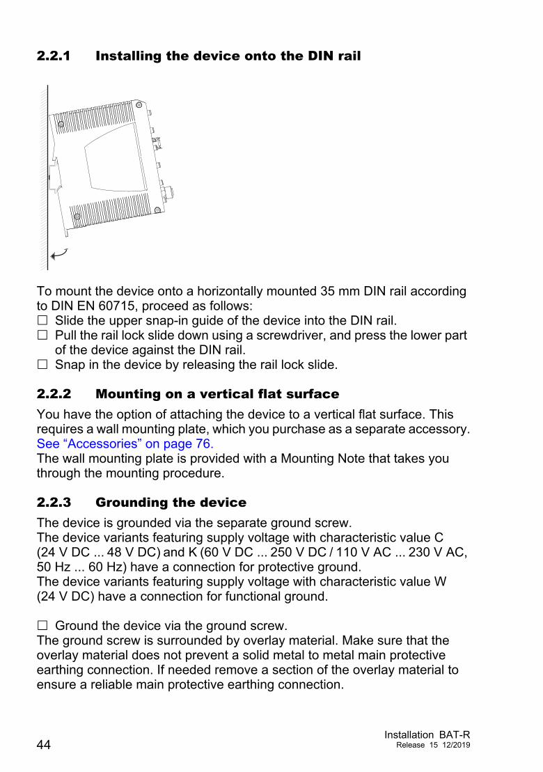
2.2.1 Installing the device onto the DIN rail
To mount the device onto a horizontally mounted 35 mm DIN rail according to DIN EN 60715, proceed as follows: Slide the upper snap-in guide of the device into the DIN rail. Pull the rail lock slide down using a screwdriver, and press the lower part
of the device against the DIN rail. Snap in the device by releasing the rail lock slide.
2.2.2 Mounting on a vertical flat surfaceYou have the option of attaching the device to a vertical flat surface. This requires a wall mounting plate, which you purchase as a separate accessory.See “Accessories” on page 76.The wall mounting plate is provided with a Mounting Note that takes you through the mounting procedure.
2.2.3 Grounding the deviceThe device is grounded via the separate ground screw.The device variants featuring supply voltage with characteristic value C (24 V DC ... 48 V DC) and K (60 V DC ... 250 V DC / 110 V AC ... 230 V AC, 50 Hz ... 60 Hz) have a connection for protective ground.The device variants featuring supply voltage with characteristic value W (24 V DC) have a connection for functional ground. Ground the device via the ground screw.The ground screw is surrounded by overlay material. Make sure that the overlay material does not prevent a solid metal to metal main protective earthing connection. If needed remove a section of the overlay material to ensure a reliable main protective earthing connection.
44Installation BAT-R
Release 15 12/2019
2.3 Installing an SFP transceiver (optional)Use only Hirschmann SFP transceivers which are suitable for usage with the device.See “Accessories” on page 76.Proceed as follows: Remove the protection cap from the SFP transceiver. Push the transceiver with the lock closed into the slot until it latches in.
2.4 Installing the antennas
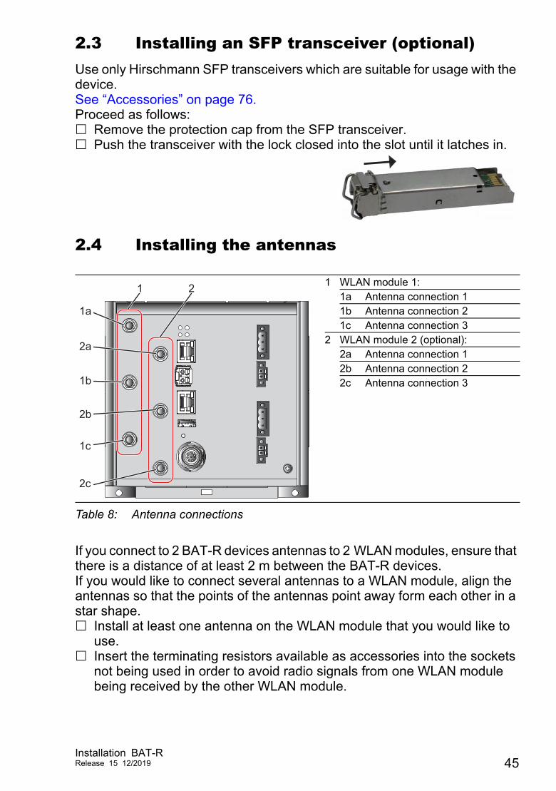
If you connect to 2 BAT-R devices antennas to 2 WLAN modules, ensure that there is a distance of at least 2 m between the BAT-R devices.If you would like to connect several antennas to a WLAN module, align the antennas so that the points of the antennas point away form each other in a star shape. Install at least one antenna on the WLAN module that you would like to
use. Insert the terminating resistors available as accessories into the sockets
not being used in order to avoid radio signals from one WLAN module being received by the other WLAN module.
1 WLAN module 1:1a Antenna connection 11b Antenna connection 21c Antenna connection 3
2 WLAN module 2 (optional):2a Antenna connection 12b Antenna connection 22c Antenna connection 3
Table 8: Antenna connections
6
1a
1b
1c
2a
2b
2c
1 2
Installation BAT-RRelease 15 12/2019 45
Relevant for use of BAT-ANT-N-MiMo-18N-IP65 with FCC and approval 2, characteristic value H. The devices are labeled as follows: “FCC ID: U99EWLAN2 and IC: 4019A-EWLAN2”Connect the BAT-ANT-N-MiMo-18N-IP65 to the WLAN module as follows: Connect the antenna port "Ver" with the WLAN antenna port 1. Connect the antenna port "+45 °" with the WLAN antenna port 2. Connect the antenna port "-45 °" with the WLAN antenna port 3. Connect the BAT-ANT-N-MiMo-18N-IP65 in this way exclusively.
2.5 Connecting the terminal blocks (optional)
The supply voltage is electrically isolated from the casing.For devices with 2 supply voltage connections:You have the option of supplying the supply voltage redundantly, without load distribution.Both supply voltage inputs are uncoupled.
WARNINGELECTRIC SHOCK Before connecting the electrical wires, always verify that the requirements listed are complied with.See “Requirements for connecting electrical wires” on page 8.See “Requirements for connecting the supply voltage” on page 10. Never insert sharp objects (small screwdrivers, wires, etc.) into the connection terminals for electric conductors, and do not touch the terminals. Failure to follow this instruction can result in death, serious injury, or equipment damage.
46Installation BAT-R
Release 15 12/2019
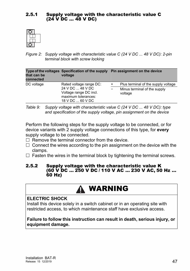
2.5.1 Supply voltage with the characteristic value C (24 V DC ... 48 V DC)
Figure 2: Supply voltage with characteristic value C (24 V DC ... 48 V DC): 2-pin terminal block with screw locking
Perform the following steps for the supply voltage to be connected, or for device variants with 2 supply voltage connections of this type, for every supply voltage to be connected. Remove the terminal connector from the device. Connect the wires according to the pin assignment on the device with the
clamps. Fasten the wires in the terminal block by tightening the terminal screws.
2.5.2 Supply voltage with the characteristic value K (60 V DC ... 250 V DC / 110 V AC ... 230 V AC, 50 Hz ... 60 Hz)
Type of the voltages that can be connected
Specification of the supply voltage
Pin assignment on the device
DC voltage Rated voltage range DC:24 V DC ... 48 V DCVoltage range DC incl. maximum tolerances:18 V DC ... 60 V DC
+ Plus terminal of the supply voltage− Minus terminal of the supply
voltage
Table 9: Supply voltage with characteristic value C (24 V DC ... 48 V DC): type and specification of the supply voltage, pin assignment on the device
WARNINGELECTRIC SHOCKInstall this device solely in a switch cabinet or in an operating site with restricted access, to which maintenance staff have exclusive access. Failure to follow this instruction can result in death, serious injury, or equipment damage.
Installation BAT-RRelease 15 12/2019 47
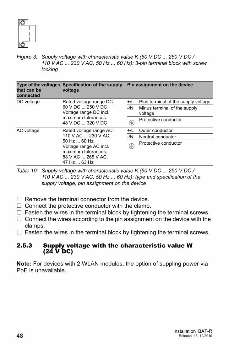
Figure 3: Supply voltage with characteristic value K (60 V DC ... 250 V DC / 110 V AC ... 230 V AC, 50 Hz ... 60 Hz): 3-pin terminal block with screw locking
Remove the terminal connector from the device. Connect the protective conductor with the clamp. Fasten the wires in the terminal block by tightening the terminal screws. Connect the wires according to the pin assignment on the device with the
clamps. Fasten the wires in the terminal block by tightening the terminal screws.
2.5.3 Supply voltage with the characteristic value W (24 V DC)
Note: For devices with 2 WLAN modules, the option of suppling power via PoE is unavailable.
Type of the voltages that can be connected
Specification of the supply voltage
Pin assignment on the device
DC voltage Rated voltage range DC:60 V DC ... 250 V DCVoltage range DC incl. maximum tolerances:48 V DC ... 320 V DC
+/L Plus terminal of the supply voltage-/N Minus terminal of the supply
voltageProtective conductor
AC voltage Rated voltage range AC:110 V AC ... 230 V AC, 50 Hz ... 60 HzVoltage range AC incl. maximum tolerances:88 V AC ... 265 V AC, 47 Hz ... 63 Hz
+/L Outer conductor-/N Neutral conductor
Protective conductor
Table 10: Supply voltage with characteristic value K (60 V DC ... 250 V DC / 110 V AC ... 230 V AC, 50 Hz ... 60 Hz): type and specification of the supply voltage, pin assignment on the device
48Installation BAT-R
Release 15 12/2019
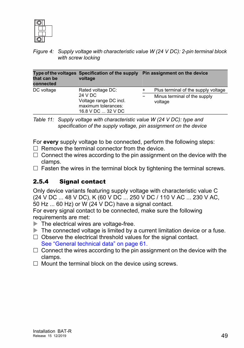
Figure 4: Supply voltage with characteristic value W (24 V DC): 2-pin terminal block with screw locking
For every supply voltage to be connected, perform the following steps: Remove the terminal connector from the device. Connect the wires according to the pin assignment on the device with the
clamps. Fasten the wires in the terminal block by tightening the terminal screws.
2.5.4 Signal contactOnly device variants featuring supply voltage with characteristic value C (24 V DC ... 48 V DC), K (60 V DC ... 250 V DC / 110 V AC ... 230 V AC, 50 Hz ... 60 Hz) or W (24 V DC) have a signal contact.For every signal contact to be connected, make sure the following requirements are met: The electrical wires are voltage-free. The connected voltage is limited by a current limitation device or a fuse. Observe the electrical threshold values for the signal contact.
See “General technical data” on page 61. Connect the wires according to the pin assignment on the device with the
clamps. Mount the terminal block on the device using screws.
Type of the voltages that can be connected
Specification of the supply voltage
Pin assignment on the device
DC voltage Rated voltage DC:24 V DCVoltage range DC incl. maximum tolerances:16.8 V DC ... 32 V DC
+ Plus terminal of the supply voltage− Minus terminal of the supply
voltage
Table 11: Supply voltage with characteristic value W (24 V DC): type and specification of the supply voltage, pin assignment on the device
Installation BAT-RRelease 15 12/2019 49
2.6 Operating the device
By connecting the supply voltage via a terminal block or a twisted pair cable (Power over Ethernet), you start the operation of the device.
2.6.1 Connecting the power supply through a terminal block
Relevant for North America:The torque for tightening the supply voltage terminal block on the device is 4.5 lb-in (0.51 Nm).The torque for tightening the terminal block for the signal contact on the device is 3 lb-in (0.34 Nm). Use screws to secure the connectors to the device. Enable the supply voltage.
2.6.2 Connecting the power supply through PoE
Note: For devices with 2 WLAN modules, the option of suppling power via PoE is unavailable.
WARNINGELECTRIC SHOCK Before connecting the electrical wires, always verify that the requirements listed are complied with.See “Requirements for connecting electrical wires” on page 8.See “Requirements for connecting the supply voltage” on page 10. Failure to follow this instruction can result in death, serious injury, or equipment damage.
NOTICEMATERIAL DAMAGEIn a PoE installation, use only devices that comply with the IEEE 802.3af/at standard.
Failure to follow this instruction can lead to equipment damage.
50Installation BAT-R
Release 15 12/2019
Only for device variants featuring supply voltage with the characteristic value P (Power supply only through PoE) or W (24 V DC):By connecting the supply voltage via PoE, you start the operation of the device.
2.7 Connecting data cables
2.7.1 Gigabit combo port
10/100/1000 Mbit/s PoE PD portFurther information:“10/100/1000 Mbit/s PoE PD port” on page 35 Connect the data cables according to your requirements.
1000 Mbit/s F/O portFurther information:“1000 Mbit/s F/O port” on page 36 Make sure that you connect LH ports exclusively with LH ports, SX ports exclusively with SX ports, and LX ports exclusively with LX ports. Connect the data cables according to your requirements.
2.7.2 10/100/1000 Mbit/s twisted-pair connection (optional)Further information:“10/100/1000 Mbit/s twisted-pair connection (optional)” on page 36 Connect the data cables according to your requirements.
Installation BAT-RRelease 15 12/2019 51
3 Making basic settingsThe IP parameters must be entered when the device is installed for the first time. The device provides the following options for configuring IP addresses: Input via the V.24 interface Entry via the HiDiscovery protocol in the applications HiDiscovery or
Industrial HiVision Configuration via BOOTP Configuration via DHCP (Option 82) AutoConfiguration Adapter You will find more information in the “User Manual Configuration Guide”. The manual is available for download on the Internet: https://www.doc.hirschmann.com
52Installation BAT-R
Release 15 12/2019
4 First login (Password change)Applies to devices with the following software release and later:HiLCOS 10.12-RU2
To help prevent undesired access to the device, it is imperative that you change the default password during initial setup.
Perform the following steps: Open the Graphical User Interface, the Command Line Interface or
LANconfig the first time you log on to the device. Log on to the device with the default password “private”.
The device prompts you to type in a new password.Note: When you log on with LANconfig, the device prompts you to type in a new password before your first configuration change.
Type in your new password.Choose a password that contains at least 8 characters which includes upper-case characters, lower-case characters, numerical digits and special characters.
Confirm your new password.
For further information see:https://hirschmann-support.belden.com/en/kb/required-password-change-new-procedure-for-first-time-login
Installation BAT-RRelease 15 12/2019 53
5 Obtain compliance for operation in the European Union
For operation in the European Union, the device must comply with the Radio Equipment Directive (RED) 2014/53/EU. The RED compliance requires compliant operation of the device in the 5 GHz band channels. Compliant operation of the device is achieved by an unchangeable determination of the country setting. Make the country setting unchangeable using the Command Line Interface (CLI), the graphical user interface or the LANconfig software. You can download the LANconfig software as an ISO image from the Hirschmann product pages (www.hirschmann.com). Perform the following work steps:
Command Line Interface (CLI) To access the possible country settings, execute the following
command: set Setup/WLAN/Country ?
Note: The country setting “Europe” is valid for all European countries. Specific country settings such as “France” or “Germany” include additional country specific channels in comparison to the “Europe” country setting.The device ignores specific country settings and uses the country setting “Europe” until the RED compliance has been obtained.
Select the desired country setting with the following command: set Setup/WLAN/Country [Country] Example:set Setup/WLAN/Country France
Execute the following command:> REDcompliance
54Installation BAT-R
Release 15 12/2019
Note: To check the country setting and correct it, type no. Then check the country setting with the following command: ls Setup/WLAN/Country.
To obtain RED compliance, type yes. This makes the country setting unchangeable. Subsequently, the device restarts.
Graphical user interface Open the Configuration > Wireless LAN > General dialog and select
the desired country setting.
Note: The country setting “Europe” is valid for all European countries. Specific country settings such as “France” or “Germany” include additional country specific channels in comparison to the “Europe” country setting.The device ignores specific country settings and uses the country setting “Europe” until the RED compliance has been obtained.
To confirm your choice, click the “Send” button.
Open the Extras > RED compliance dialog.
Note: To check the country setting and correct it, open the Configuration > Wireless LAN > General dialog.
To obtain RED compliance, click the “Confirm RED compliance” button. This makes the country setting unchangeable. Subsequently, the device restarts.
LANconfig In the LANconfig device overview, highlight the row containing the
desired device.
In the menu bar, select Device > Configure.
Open the Configuration > Wireless LAN > General dialog and select the desired country setting.
Note: The country setting “Europe” is valid for all European countries. Specific country settings such as “France” or “Germany” include additional country specific channels in comparison to the “Europe” country setting.The device ignores specific country settings and uses the country setting “Europe” until the RED compliance has been obtained.
Installation BAT-RRelease 15 12/2019 55
To confirm your choice, click the “OK” button.
In the LANconfig device overview, highlight the row containing the desired device.
In the menu bar, select Device > RED compliance.
Note: To check the country setting and correct it, click the “No” button. Then open the Configuration > Wireless LAN > General dialog.
To obtain RED compliance, click the “Yes” button. This makes the country setting unchangeable. Subsequently, the device restarts.
56Installation BAT-R
Release 15 12/2019
6 Configuring the transmit power
Note: The operator of a WLAN radio installation must adhere to the applicable transmission threshold values.
Use the graphical user interface or the LANconfig software. You can download the LANconfig software as an ISO image from the Hirschmann product pages (www.hirschmann.com). In the graphical user interface, proceed as follows: In the menu tree, open the Configuration > Wireless LAN > General
dialog. In the “General” tab, specify in the “General” frame the country in which
you install the device, and click the “Send” button.
Note: For devices that are operated in the European Union perform thework steps described in chapter “Obtain compliance for operation in the European Union” on page 54.
In the menu tree, open the Configuration > Wireless LAN > General > Physical WLAN settings - Radio dialog.
In the “General” tab, click in the “Interface” column the physical WLAN interface to which you connect the antenna.
Installation BAT-RRelease 15 12/2019 57
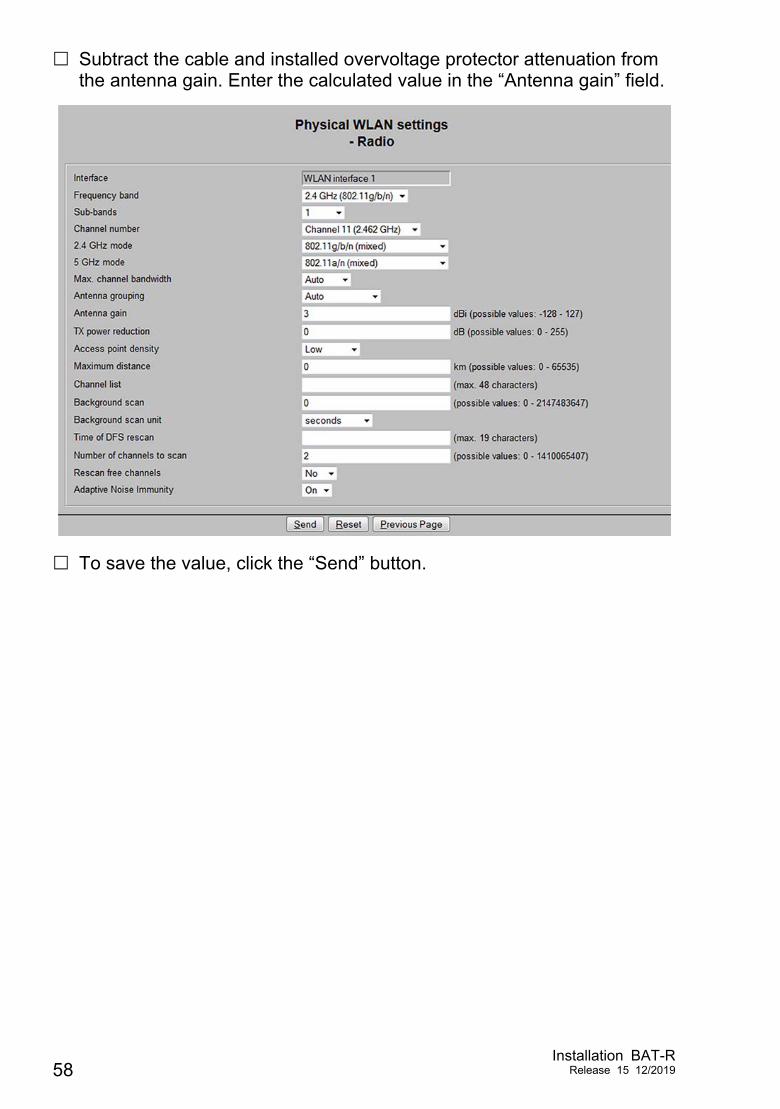
Subtract the cable and installed overvoltage protector attenuation from the antenna gain. Enter the calculated value in the “Antenna gain” field.
To save the value, click the “Send” button.
58Installation BAT-R
Release 15 12/2019
7 Maintenance and service When designing this device, Hirschmann largely avoided using high-wear
parts. The parts subject to wear and tear are dimensioned to last longer than the lifetime of the product when it is operated normally. Operate this device according to the specifications.
Relays are subject to natural wear. This wear depends on the frequency of the switching operations. Check the resistance of the closed relay contacts and the switching function depending on the frequency of the switching operations.
Hirschmann is continually working on improving and developing their software. Check regularly whether there is an updated version of the software that provides you with additional benefits. You find information and software downloads on the Hirschmann product pages on the Internet (http://www.hirschmann.com).
Depending on the degree of pollution in the operating environment, check at regular intervals that the ventilation slots in the device are not obstructed.
Note: You find information on settling complaints on the Internet at http://www.beldensolutions.com/en/Service/Repairs/index.phtml.
Installation BAT-RRelease 15 12/2019 59
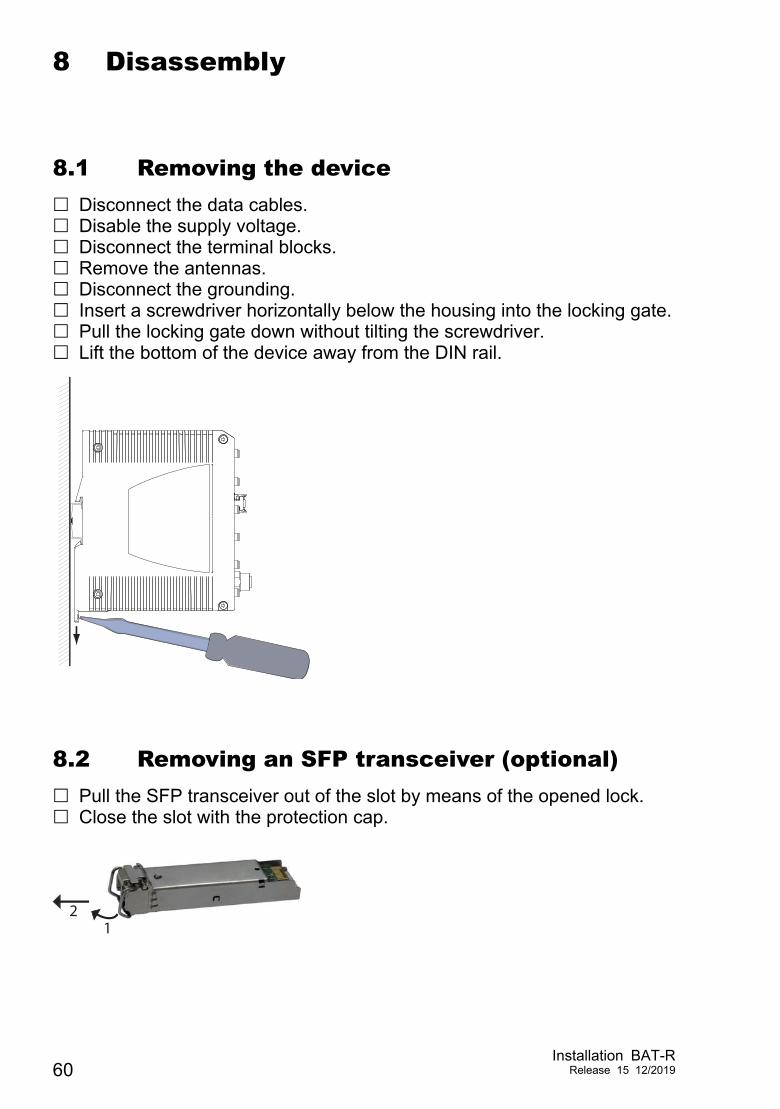
8 Disassembly
8.1 Removing the device Disconnect the data cables. Disable the supply voltage. Disconnect the terminal blocks. Remove the antennas. Disconnect the grounding. Insert a screwdriver horizontally below the housing into the locking gate. Pull the locking gate down without tilting the screwdriver. Lift the bottom of the device away from the DIN rail.
8.2 Removing an SFP transceiver (optional) Pull the SFP transceiver out of the slot by means of the opened lock. Close the slot with the protection cap.
12
60Installation BAT-R
Release 15 12/2019
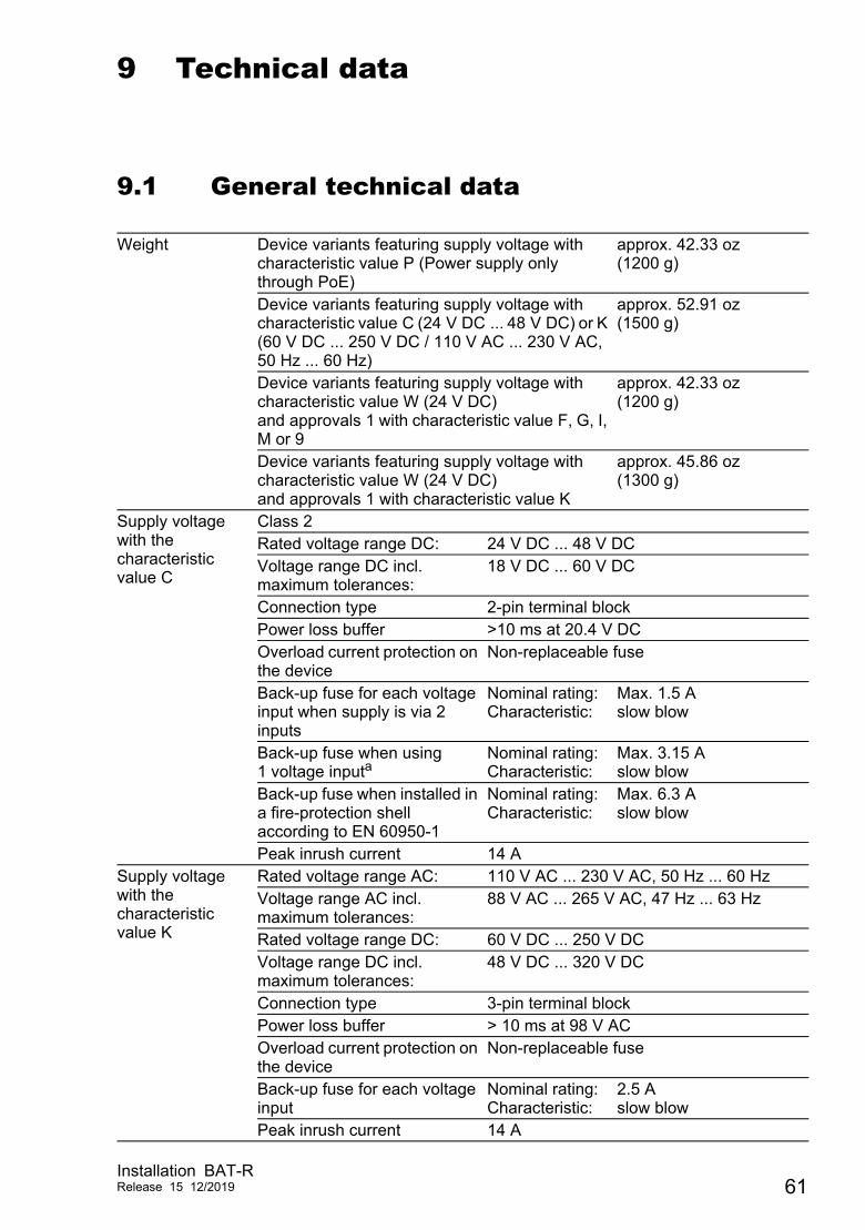
9 Technical data
9.1 General technical data
Weight Device variants featuring supply voltage with characteristic value P (Power supply only through PoE)
approx. 42.33 oz (1200 g)
Device variants featuring supply voltage with characteristic value C (24 V DC ... 48 V DC) or K (60 V DC ... 250 V DC / 110 V AC ... 230 V AC, 50 Hz ... 60 Hz)
approx. 52.91 oz (1500 g)
Device variants featuring supply voltage with characteristic value W (24 V DC)and approvals 1 with characteristic value F, G, I, M or 9
approx. 42.33 oz (1200 g)
Device variants featuring supply voltage with characteristic value W (24 V DC)and approvals 1 with characteristic value K
approx. 45.86 oz (1300 g)
Supply voltage with the characteristic value C
Class 2Rated voltage range DC: 24 V DC ... 48 V DCVoltage range DC incl. maximum tolerances:
18 V DC ... 60 V DC
Connection type 2-pin terminal blockPower loss buffer >10 ms at 20.4 V DCOverload current protection on the device
Non-replaceable fuse
Back-up fuse for each voltage input when supply is via 2 inputs
Nominal rating: Characteristic:
Max. 1.5 Aslow blow
Back-up fuse when using 1 voltage inputa
Nominal rating: Characteristic:
Max. 3.15 Aslow blow
Back-up fuse when installed in a fire-protection shell according to EN 60950-1
Nominal rating: Characteristic:
Max. 6.3 Aslow blow
Peak inrush current 14 ASupply voltage with the characteristic value K
Rated voltage range AC: 110 V AC ... 230 V AC, 50 Hz ... 60 HzVoltage range AC incl. maximum tolerances:
88 V AC ... 265 V AC, 47 Hz ... 63 Hz
Rated voltage range DC: 60 V DC ... 250 V DCVoltage range DC incl. maximum tolerances:
48 V DC ... 320 V DC
Connection type 3-pin terminal blockPower loss buffer > 10 ms at 98 V ACOverload current protection on the device
Non-replaceable fuse
Back-up fuse for each voltage input
Nominal rating: Characteristic:
2.5 Aslow blow
Peak inrush current 14 A
Installation BAT-RRelease 15 12/2019 61
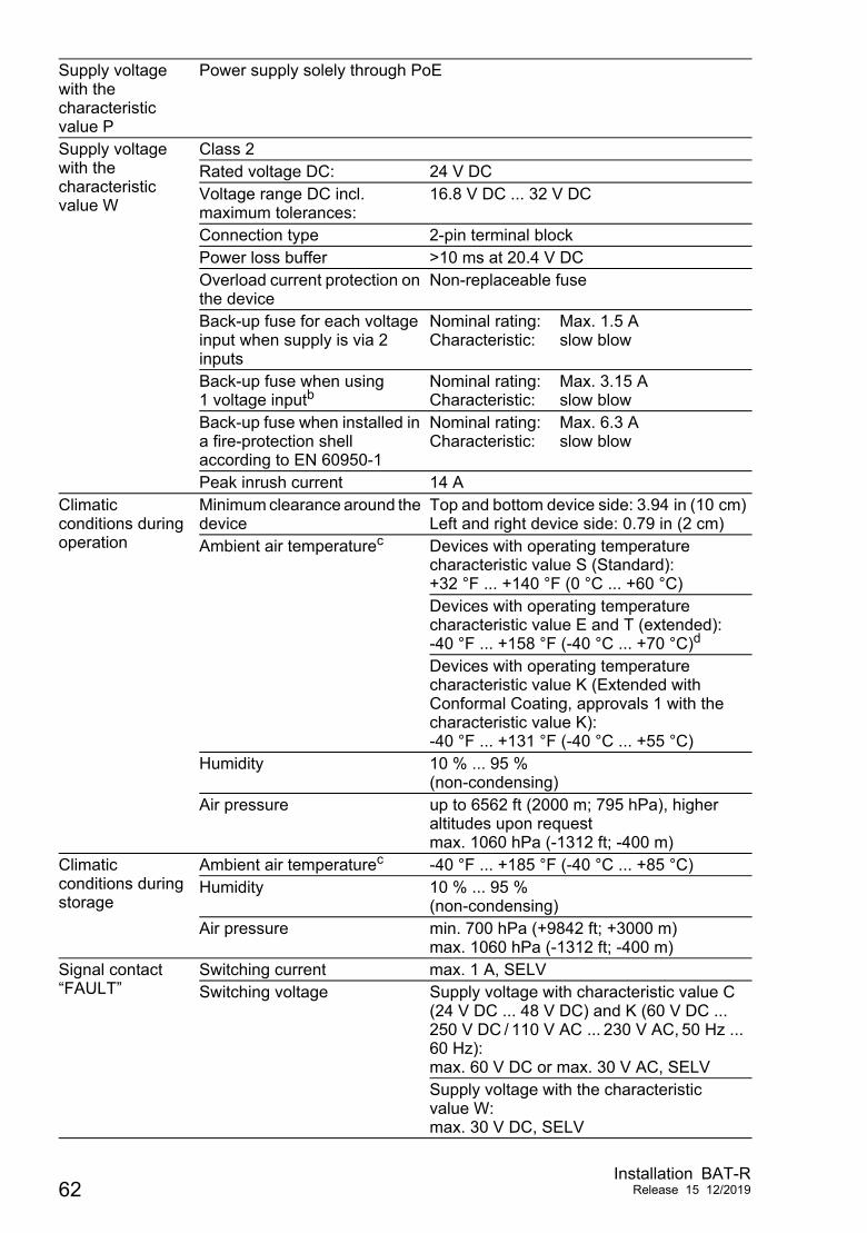
Supply voltage with the characteristic value P
Power supply solely through PoE
Supply voltage with the characteristic value W
Class 2Rated voltage DC: 24 V DCVoltage range DC incl. maximum tolerances:
16.8 V DC ... 32 V DC
Connection type 2-pin terminal blockPower loss buffer >10 ms at 20.4 V DCOverload current protection on the device
Non-replaceable fuse
Back-up fuse for each voltage input when supply is via 2 inputs
Nominal rating: Characteristic:
Max. 1.5 Aslow blow
Back-up fuse when using 1 voltage inputb
Nominal rating: Characteristic:
Max. 3.15 Aslow blow
Back-up fuse when installed in a fire-protection shell according to EN 60950-1
Nominal rating: Characteristic:
Max. 6.3 Aslow blow
Peak inrush current 14 AClimatic conditions during operation
Minimum clearance around the device
Top and bottom device side: 3.94 in (10 cm)Left and right device side: 0.79 in (2 cm)
Ambient air temperaturec Devices with operating temperature characteristic value S (Standard):+32 °F ... +140 °F (0 °C ... +60 °C) Devices with operating temperature characteristic value E and T (extended):-40 °F ... +158 °F (-40 °C ... +70 °C)d
Devices with operating temperature characteristic value K (Extended with Conformal Coating, approvals 1 with the characteristic value K):-40 °F ... +131 °F (-40 °C ... +55 °C)
Humidity 10 % ... 95 %(non-condensing)
Air pressure up to 6562 ft (2000 m; 795 hPa), higher altitudes upon requestmax. 1060 hPa (-1312 ft; -400 m)
Climatic conditions during storage
Ambient air temperaturec -40 °F ... +185 °F (-40 °C ... +85 °C) Humidity 10 % ... 95 %
(non-condensing)Air pressure min. 700 hPa (+9842 ft; +3000 m)
max. 1060 hPa (-1312 ft; -400 m)Signal contact “FAULT”
Switching current max. 1 A, SELVSwitching voltage Supply voltage with characteristic value C
(24 V DC ... 48 V DC) and K (60 V DC ... 250 V DC / 110 V AC ... 230 V AC, 50 Hz ... 60 Hz):max. 60 V DC or max. 30 V AC, SELVSupply voltage with the characteristic value W:max. 30 V DC, SELV
62Installation BAT-R
Release 15 12/2019
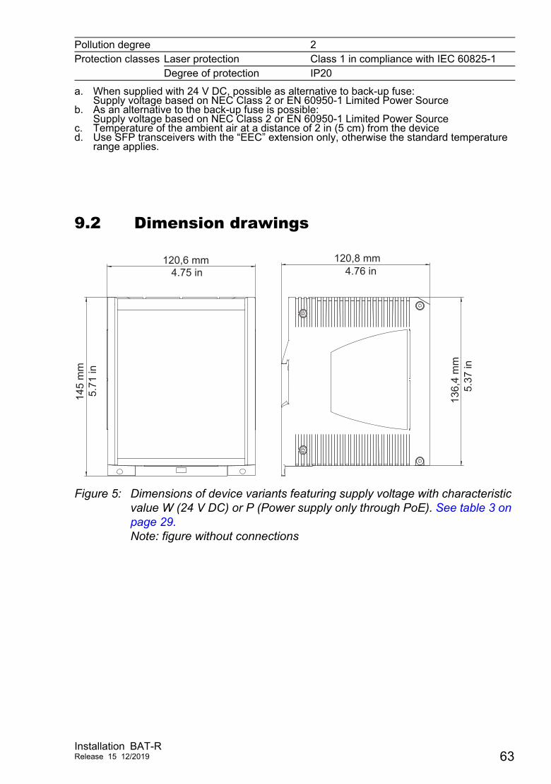
9.2 Dimension drawings
Figure 5: Dimensions of device variants featuring supply voltage with characteristic value W (24 V DC) or P (Power supply only through PoE). See table 3 on page 29.Note: figure without connections
Pollution degree 2Protection classes Laser protection Class 1 in compliance with IEC 60825-1
Degree of protection IP20
a. When supplied with 24 V DC, possible as alternative to back-up fuse:Supply voltage based on NEC Class 2 or EN 60950-1 Limited Power Source
b. As an alternative to the back-up fuse is possible:Supply voltage based on NEC Class 2 or EN 60950-1 Limited Power Source
c. Temperature of the ambient air at a distance of 2 in (5 cm) from the deviced. Use SFP transceivers with the “EEC” extension only, otherwise the standard temperature
range applies.
120,6 mm
145
mm
136,
4 m
m
120,8 mm4.75 in
5.71
in
4.76 in
5.37
in
Installation BAT-RRelease 15 12/2019 63
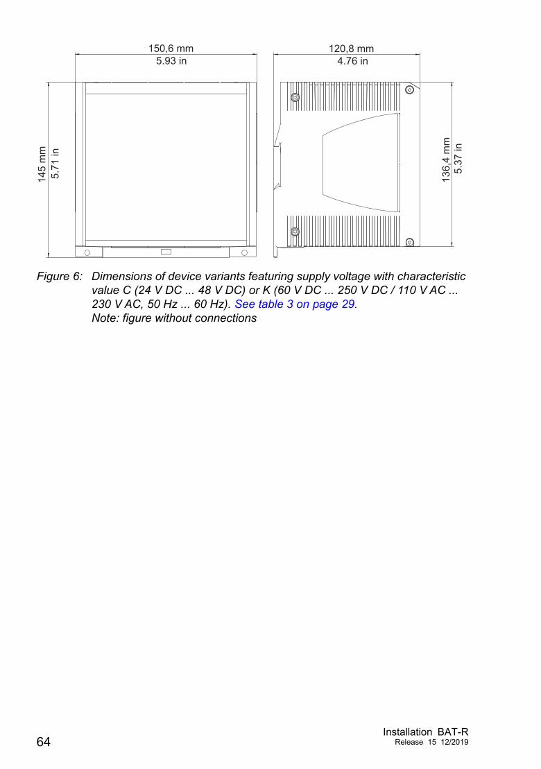
Figure 6: Dimensions of device variants featuring supply voltage with characteristic value C (24 V DC ... 48 V DC) or K (60 V DC ... 250 V DC / 110 V AC ... 230 V AC, 50 Hz ... 60 Hz). See table 3 on page 29.Note: figure without connections
145
mm
150,6 mm 120,8 mm
136,
4 m
m
5.93 in5.
71 in
4.76 in
5.37
in
64Installation BAT-R
Release 15 12/2019
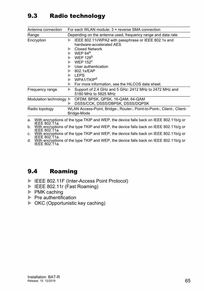
9.3 Radio technology
9.4 Roaming IEEE 802.11F (Inter-Access Point Protocol) IEEE 802.11r (Fast Roaming) PMK caching Pre authentification OKC (Opportunistic key caching)
Antenna connection For each WLAN module: 3 × reverse SMA connectionRange Depending on the antenna used, frequency range and data rateEncryption IEEE 802.11i/WPA2 with passphrase or IEEE 802.1x and
hardware-accelerated AES Closed Network WEP 64a
WEP 128b
WEP 152c
User authentication 802.1x/EAP LEPS WPA1/TKIPd
For more information, see the HiLCOS data sheet.
a. With encryptions of the type TKIP and WEP, the device falls back on IEEE 802.11b/g or IEEE 802.11a.
b. With encryptions of the type TKIP and WEP, the device falls back on IEEE 802.11b/g or IEEE 802.11a.
c. With encryptions of the type TKIP and WEP, the device falls back on IEEE 802.11b/g or IEEE 802.11a.
d. With encryptions of the type TKIP and WEP, the device falls back on IEEE 802.11b/g or IEEE 802.11a.
Frequency range Support of 2.4 GHz and 5 GHz: 2412 MHz to 2472 MHz and 5180 MHz to 5825 MHz
Modulation technology OFDM: BPSK, QPSK, 16-QAM, 64-QAM DSSS/CCK, DSSS/DBPSK, DSSS/DQPSK
Radio topology WLAN Access-Point, Bridge-, Router-, Point-to-Point-, Client-, Client-Bridge-Mode
Installation BAT-RRelease 15 12/2019 65
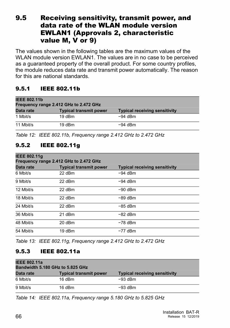
9.5 Receiving sensitivity, transmit power, and data rate of the WLAN module version EWLAN1 (Approvals 2, characteristic value M, V or 9)
The values shown in the following tables are the maximum values of the WLAN module version EWLAN1. The values are in no case to be perceived as a guaranteed property of the overall product. For some country profiles, the module reduces data rate and transmit power automatically. The reason for this are national standards.
9.5.1 IEEE 802.11b
9.5.2 IEEE 802.11g
9.5.3 IEEE 802.11a
IEEE 802.11bFrequency range 2.412 GHz to 2.472 GHzData rate Typical transmit power Typical receiving sensitivity1 Mbit/s 19 dBm −94 dBm
11 Mbit/s 19 dBm −94 dBm
Table 12: IEEE 802.11b, Frequency range 2.412 GHz to 2.472 GHz
IEEE 802.11gFrequency range 2.412 GHz to 2.472 GHzData rate Typical transmit power Typical receiving sensitivity6 Mbit/s 22 dBm −94 dBm
9 Mbit/s 22 dBm −94 dBm
12 Mbit/s 22 dBm −90 dBm
18 Mbit/s 22 dBm −89 dBm
24 Mbit/s 22 dBm −85 dBm
36 Mbit/s 21 dBm −82 dBm
48 Mbit/s 20 dBm −78 dBm
54 Mbit/s 19 dBm −77 dBm
Table 13: IEEE 802.11g, Frequency range 2.412 GHz to 2.472 GHz
IEEE 802.11aBandwidth 5.180 GHz to 5.825 GHzData rate Typical transmit power Typical receiving sensitivity6 Mbit/s 16 dBm −93 dBm
9 Mbit/s 16 dBm −93 dBm
Table 14: IEEE 802.11a, Frequency range 5.180 GHz to 5.825 GHz
66Installation BAT-R
Release 15 12/2019
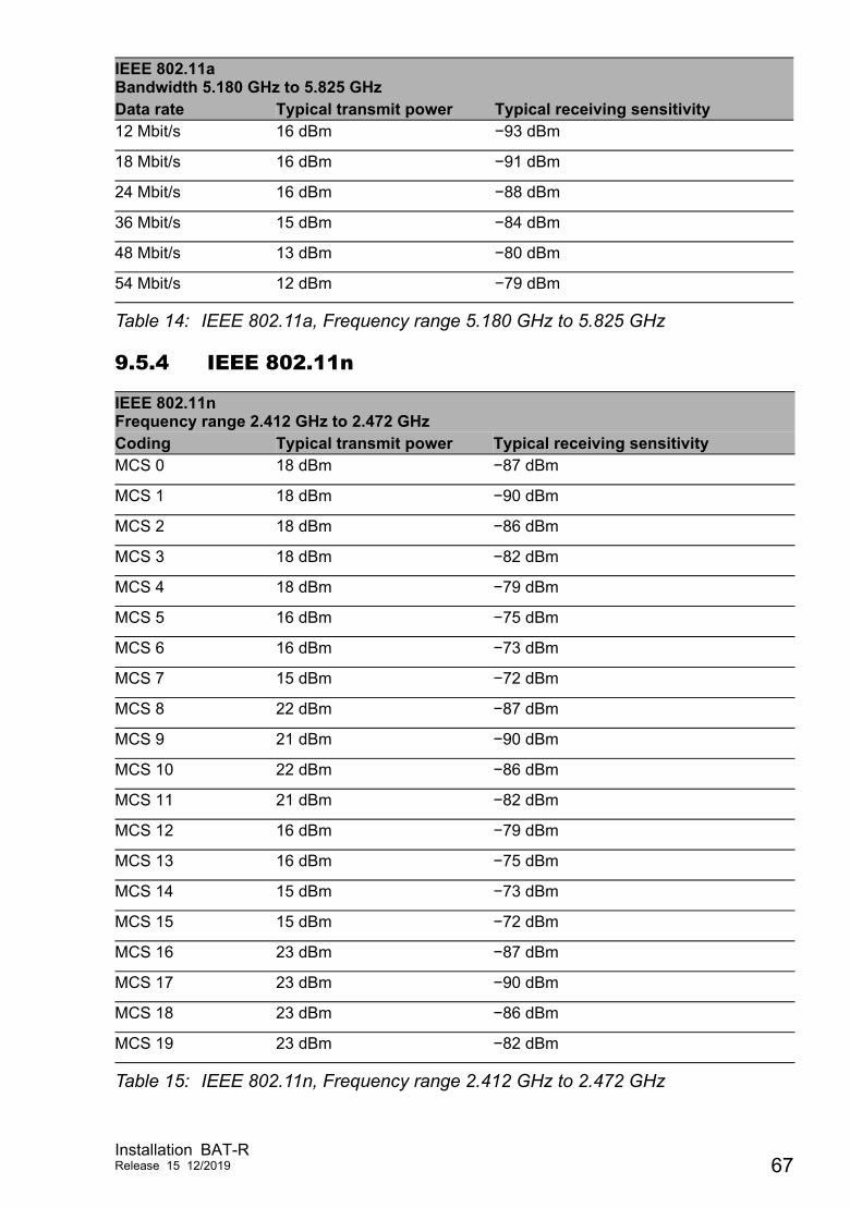
9.5.4 IEEE 802.11n
12 Mbit/s 16 dBm −93 dBm
18 Mbit/s 16 dBm −91 dBm
24 Mbit/s 16 dBm −88 dBm
36 Mbit/s 15 dBm −84 dBm
48 Mbit/s 13 dBm −80 dBm
54 Mbit/s 12 dBm −79 dBm
IEEE 802.11nFrequency range 2.412 GHz to 2.472 GHzCoding Typical transmit power Typical receiving sensitivityMCS 0 18 dBm −87 dBm
MCS 1 18 dBm −90 dBm
MCS 2 18 dBm −86 dBm
MCS 3 18 dBm −82 dBm
MCS 4 18 dBm −79 dBm
MCS 5 16 dBm −75 dBm
MCS 6 16 dBm −73 dBm
MCS 7 15 dBm −72 dBm
MCS 8 22 dBm −87 dBm
MCS 9 21 dBm −90 dBm
MCS 10 22 dBm −86 dBm
MCS 11 21 dBm −82 dBm
MCS 12 16 dBm −79 dBm
MCS 13 16 dBm −75 dBm
MCS 14 15 dBm −73 dBm
MCS 15 15 dBm −72 dBm
MCS 16 23 dBm −87 dBm
MCS 17 23 dBm −90 dBm
MCS 18 23 dBm −86 dBm
MCS 19 23 dBm −82 dBm
Table 15: IEEE 802.11n, Frequency range 2.412 GHz to 2.472 GHz
IEEE 802.11aBandwidth 5.180 GHz to 5.825 GHzData rate Typical transmit power Typical receiving sensitivity
Table 14: IEEE 802.11a, Frequency range 5.180 GHz to 5.825 GHz
Installation BAT-RRelease 15 12/2019 67
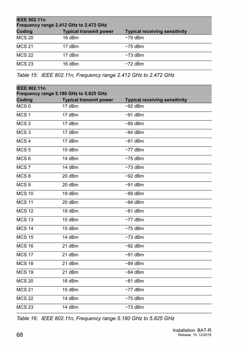
MCS 20 16 dBm −79 dBm
MCS 21 17 dBm −75 dBm
MCS 22 17 dBm −73 dBm
MCS 23 16 dBm −72 dBm
IEEE 802.11nFrequency range 5.180 GHz to 5.825 GHzCoding Typical transmit power Typical receiving sensitivityMCS 0 17 dBm −92 dBm
MCS 1 17 dBm −91 dBm
MCS 2 17 dBm −89 dBm
MCS 3 17 dBm −84 dBm
MCS 4 17 dBm −81 dBm
MCS 5 15 dBm −77 dBm
MCS 6 14 dBm −75 dBm
MCS 7 14 dBm −73 dBm
MCS 8 20 dBm −92 dBm
MCS 9 20 dBm −91 dBm
MCS 10 19 dBm −89 dBm
MCS 11 20 dBm −84 dBm
MCS 12 18 dBm −81 dBm
MCS 13 15 dBm −77 dBm
MCS 14 15 dBm −75 dBm
MCS 15 14 dBm −73 dBm
MCS 16 21 dBm −92 dBm
MCS 17 21 dBm −91 dBm
MCS 18 21 dBm −89 dBm
MCS 19 21 dBm −84 dBm
MCS 20 16 dBm −81 dBm
MCS 21 15 dBm −77 dBm
MCS 22 14 dBm −75 dBm
MCS 23 14 dBm −73 dBm
Table 16: IEEE 802.11n, Frequency range 5.180 GHz to 5.825 GHz
IEEE 802.11nFrequency range 2.412 GHz to 2.472 GHzCoding Typical transmit power Typical receiving sensitivity
Table 15: IEEE 802.11n, Frequency range 2.412 GHz to 2.472 GHz
68Installation BAT-R
Release 15 12/2019
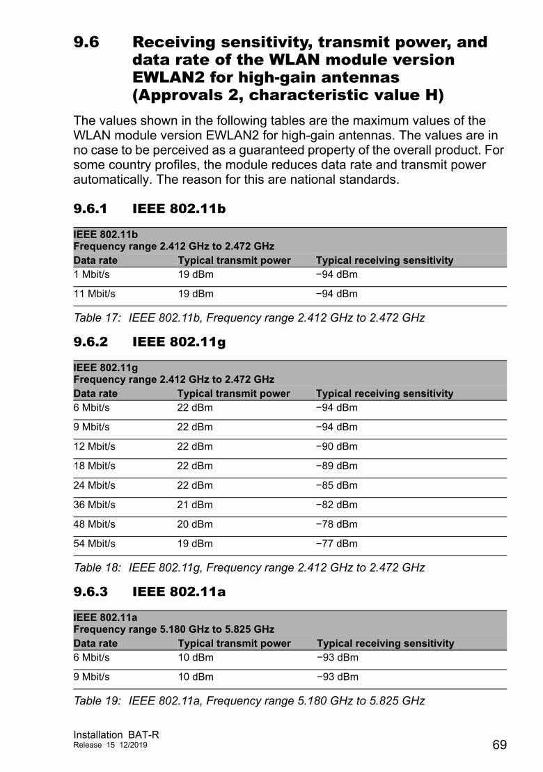
9.6 Receiving sensitivity, transmit power, and data rate of the WLAN module version EWLAN2 for high-gain antennas (Approvals 2, characteristic value H)
The values shown in the following tables are the maximum values of the WLAN module version EWLAN2 for high-gain antennas. The values are in no case to be perceived as a guaranteed property of the overall product. For some country profiles, the module reduces data rate and transmit power automatically. The reason for this are national standards.
9.6.1 IEEE 802.11b
9.6.2 IEEE 802.11g
9.6.3 IEEE 802.11a
IEEE 802.11bFrequency range 2.412 GHz to 2.472 GHzData rate Typical transmit power Typical receiving sensitivity1 Mbit/s 19 dBm −94 dBm
11 Mbit/s 19 dBm −94 dBm
Table 17: IEEE 802.11b, Frequency range 2.412 GHz to 2.472 GHz
IEEE 802.11gFrequency range 2.412 GHz to 2.472 GHzData rate Typical transmit power Typical receiving sensitivity6 Mbit/s 22 dBm −94 dBm
9 Mbit/s 22 dBm −94 dBm
12 Mbit/s 22 dBm −90 dBm
18 Mbit/s 22 dBm −89 dBm
24 Mbit/s 22 dBm −85 dBm
36 Mbit/s 21 dBm −82 dBm
48 Mbit/s 20 dBm −78 dBm
54 Mbit/s 19 dBm −77 dBm
Table 18: IEEE 802.11g, Frequency range 2.412 GHz to 2.472 GHz
IEEE 802.11aFrequency range 5.180 GHz to 5.825 GHzData rate Typical transmit power Typical receiving sensitivity6 Mbit/s 10 dBm −93 dBm
9 Mbit/s 10 dBm −93 dBm
Table 19: IEEE 802.11a, Frequency range 5.180 GHz to 5.825 GHz
Installation BAT-RRelease 15 12/2019 69
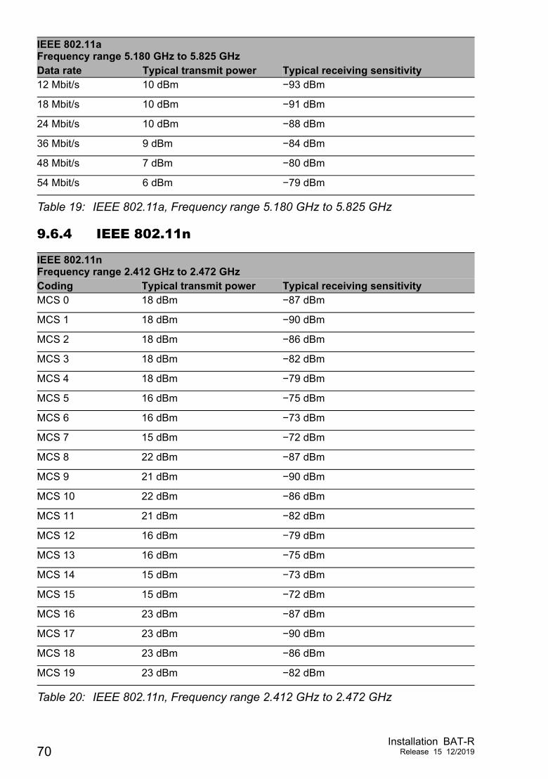
9.6.4 IEEE 802.11n
12 Mbit/s 10 dBm −93 dBm
18 Mbit/s 10 dBm −91 dBm
24 Mbit/s 10 dBm −88 dBm
36 Mbit/s 9 dBm −84 dBm
48 Mbit/s 7 dBm −80 dBm
54 Mbit/s 6 dBm −79 dBm
IEEE 802.11nFrequency range 2.412 GHz to 2.472 GHzCoding Typical transmit power Typical receiving sensitivityMCS 0 18 dBm −87 dBm
MCS 1 18 dBm −90 dBm
MCS 2 18 dBm −86 dBm
MCS 3 18 dBm −82 dBm
MCS 4 18 dBm −79 dBm
MCS 5 16 dBm −75 dBm
MCS 6 16 dBm −73 dBm
MCS 7 15 dBm −72 dBm
MCS 8 22 dBm −87 dBm
MCS 9 21 dBm −90 dBm
MCS 10 22 dBm −86 dBm
MCS 11 21 dBm −82 dBm
MCS 12 16 dBm −79 dBm
MCS 13 16 dBm −75 dBm
MCS 14 15 dBm −73 dBm
MCS 15 15 dBm −72 dBm
MCS 16 23 dBm −87 dBm
MCS 17 23 dBm −90 dBm
MCS 18 23 dBm −86 dBm
MCS 19 23 dBm −82 dBm
Table 20: IEEE 802.11n, Frequency range 2.412 GHz to 2.472 GHz
IEEE 802.11aFrequency range 5.180 GHz to 5.825 GHzData rate Typical transmit power Typical receiving sensitivity
Table 19: IEEE 802.11a, Frequency range 5.180 GHz to 5.825 GHz
70Installation BAT-R
Release 15 12/2019
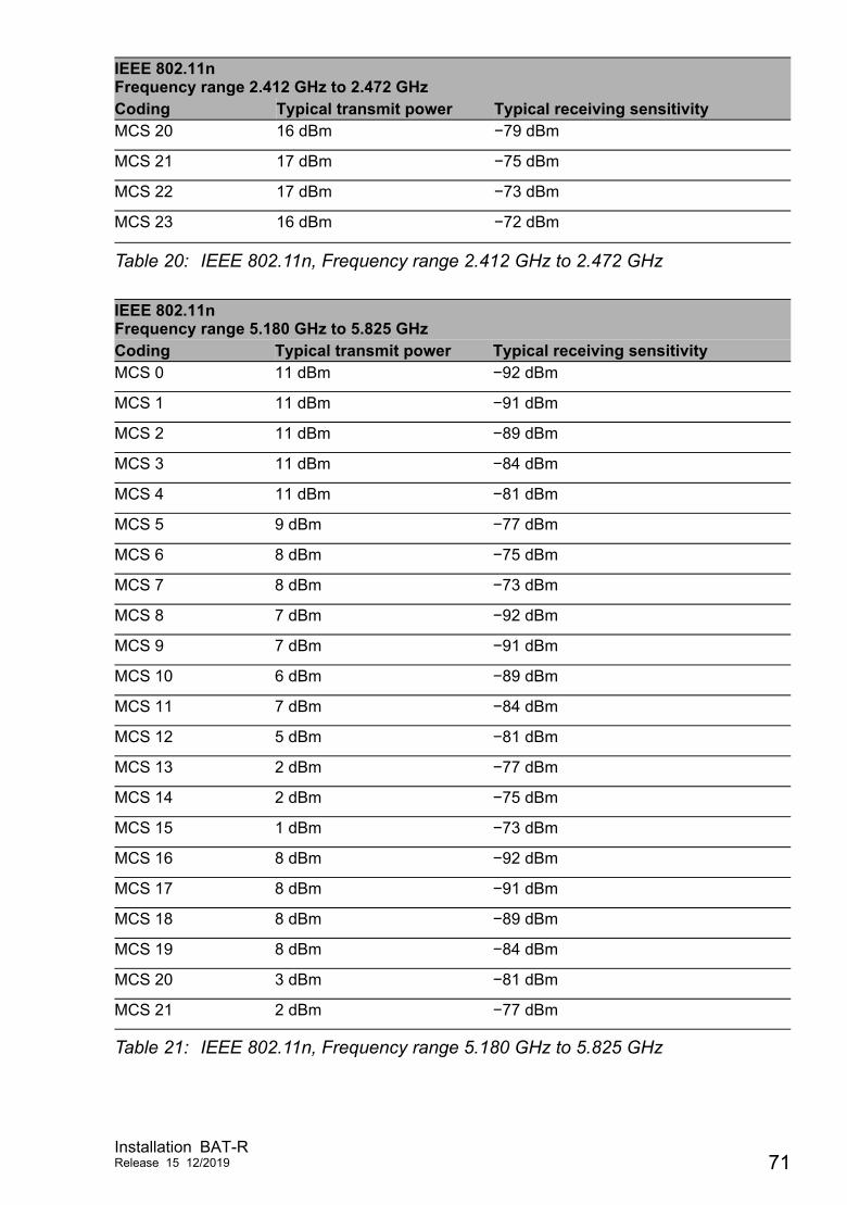
MCS 20 16 dBm −79 dBm
MCS 21 17 dBm −75 dBm
MCS 22 17 dBm −73 dBm
MCS 23 16 dBm −72 dBm
IEEE 802.11nFrequency range 5.180 GHz to 5.825 GHzCoding Typical transmit power Typical receiving sensitivityMCS 0 11 dBm −92 dBm
MCS 1 11 dBm −91 dBm
MCS 2 11 dBm −89 dBm
MCS 3 11 dBm −84 dBm
MCS 4 11 dBm −81 dBm
MCS 5 9 dBm −77 dBm
MCS 6 8 dBm −75 dBm
MCS 7 8 dBm −73 dBm
MCS 8 7 dBm −92 dBm
MCS 9 7 dBm −91 dBm
MCS 10 6 dBm −89 dBm
MCS 11 7 dBm −84 dBm
MCS 12 5 dBm −81 dBm
MCS 13 2 dBm −77 dBm
MCS 14 2 dBm −75 dBm
MCS 15 1 dBm −73 dBm
MCS 16 8 dBm −92 dBm
MCS 17 8 dBm −91 dBm
MCS 18 8 dBm −89 dBm
MCS 19 8 dBm −84 dBm
MCS 20 3 dBm −81 dBm
MCS 21 2 dBm −77 dBm
Table 21: IEEE 802.11n, Frequency range 5.180 GHz to 5.825 GHz
IEEE 802.11nFrequency range 2.412 GHz to 2.472 GHzCoding Typical transmit power Typical receiving sensitivity
Table 20: IEEE 802.11n, Frequency range 2.412 GHz to 2.472 GHz
Installation BAT-RRelease 15 12/2019 71
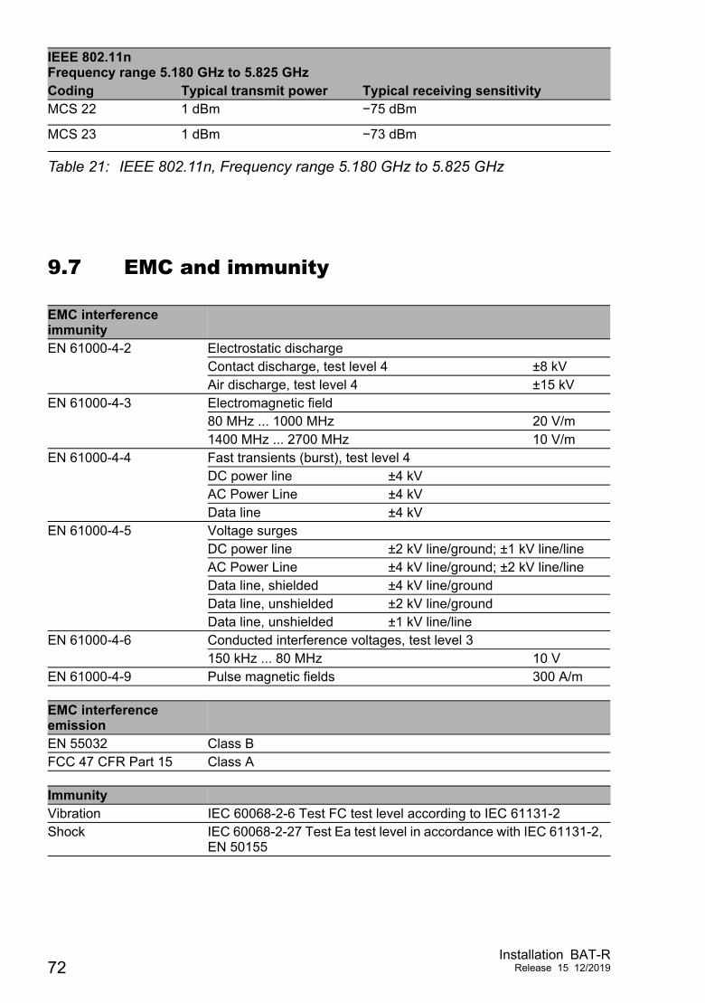
9.7 EMC and immunity
MCS 22 1 dBm −75 dBm
MCS 23 1 dBm −73 dBm
EMC interference immunityEN 61000-4-2 Electrostatic discharge
Contact discharge, test level 4 ±8 kVAir discharge, test level 4 ±15 kV
EN 61000-4-3 Electromagnetic field80 MHz ... 1000 MHz 20 V/m1400 MHz ... 2700 MHz 10 V/m
EN 61000-4-4 Fast transients (burst), test level 4DC power line ±4 kVAC Power Line ±4 kVData line ±4 kV
EN 61000-4-5 Voltage surgesDC power line ±2 kV line/ground; ±1 kV line/line AC Power Line ±4 kV line/ground; ±2 kV line/line Data line, shielded ±4 kV line/groundData line, unshielded ±2 kV line/groundData line, unshielded ±1 kV line/line
EN 61000-4-6 Conducted interference voltages, test level 3150 kHz ... 80 MHz 10 V
EN 61000-4-9 Pulse magnetic fields 300 A/m
EMC interference emissionEN 55032 Class BFCC 47 CFR Part 15 Class A
ImmunityVibration IEC 60068-2-6 Test FC test level according to IEC 61131-2Shock IEC 60068-2-27 Test Ea test level in accordance with IEC 61131-2,
EN 50155
IEEE 802.11nFrequency range 5.180 GHz to 5.825 GHzCoding Typical transmit power Typical receiving sensitivity
Table 21: IEEE 802.11n, Frequency range 5.180 GHz to 5.825 GHz
72Installation BAT-R
Release 15 12/2019
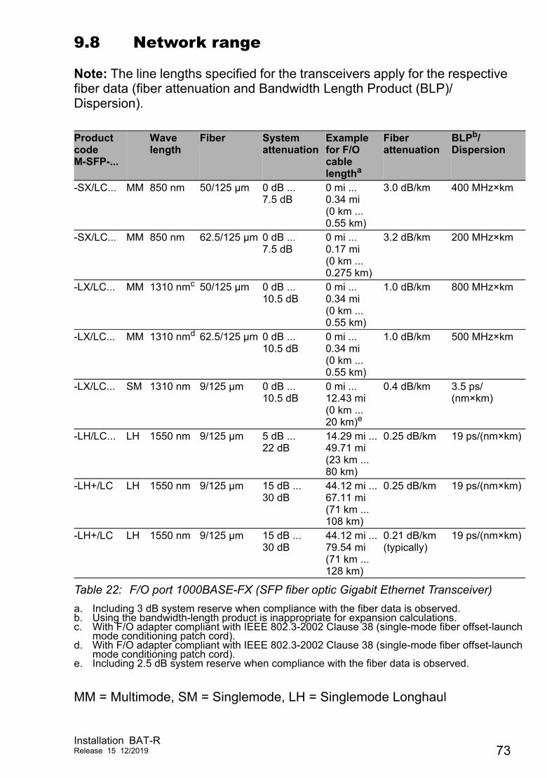
9.8 Network range
Note: The line lengths specified for the transceivers apply for the respective fiber data (fiber attenuation and Bandwidth Length Product (BLP)/ Dispersion).
MM = Multimode, SM = Singlemode, LH = Singlemode Longhaul
Product codeM-SFP-...
Wave length
Fiber System attenuation
Example for F/O cable lengtha
a. Including 3 dB system reserve when compliance with the fiber data is observed.
Fiber attenuation
BLPb/Dispersion
b. Using the bandwidth-length product is inappropriate for expansion calculations.
-SX/LC... MM 850 nm 50/125 µm 0 dB ... 7.5 dB
0 mi ... 0.34 mi (0 km ... 0.55 km)
3.0 dB/km 400 MHz×km
-SX/LC... MM 850 nm 62.5/125 µm 0 dB ... 7.5 dB
0 mi ... 0.17 mi (0 km ... 0.275 km)
3.2 dB/km 200 MHz×km
-LX/LC... MM 1310 nmc
c. With F/O adapter compliant with IEEE 802.3-2002 Clause 38 (single-mode fiber offset-launchmode conditioning patch cord).
50/125 µm 0 dB ... 10.5 dB
0 mi ... 0.34 mi (0 km ... 0.55 km)
1.0 dB/km 800 MHz×km
-LX/LC... MM 1310 nmd
d. With F/O adapter compliant with IEEE 802.3-2002 Clause 38 (single-mode fiber offset-launchmode conditioning patch cord).
62.5/125 µm 0 dB ... 10.5 dB
0 mi ... 0.34 mi (0 km ... 0.55 km)
1.0 dB/km 500 MHz×km
-LX/LC... SM 1310 nm 9/125 µm 0 dB ... 10.5 dB
0 mi ... 12.43 mi (0 km ... 20 km)e
e. Including 2.5 dB system reserve when compliance with the fiber data is observed.
0.4 dB/km 3.5 ps/(nm×km)
-LH/LC... LH 1550 nm 9/125 µm 5 dB ... 22 dB
14.29 mi ... 49.71 mi (23 km ... 80 km)
0.25 dB/km 19 ps/(nm×km)
-LH+/LC LH 1550 nm 9/125 µm 15 dB ... 30 dB
44.12 mi ... 67.11 mi (71 km ... 108 km)
0.25 dB/km 19 ps/(nm×km)
-LH+/LC LH 1550 nm 9/125 µm 15 dB ... 30 dB
44.12 mi ... 79.54 mi (71 km ... 128 km)
0.21 dB/km (typically)
19 ps/(nm×km)
Table 22: F/O port 1000BASE-FX (SFP fiber optic Gigabit Ethernet Transceiver)
Installation BAT-RRelease 15 12/2019 73
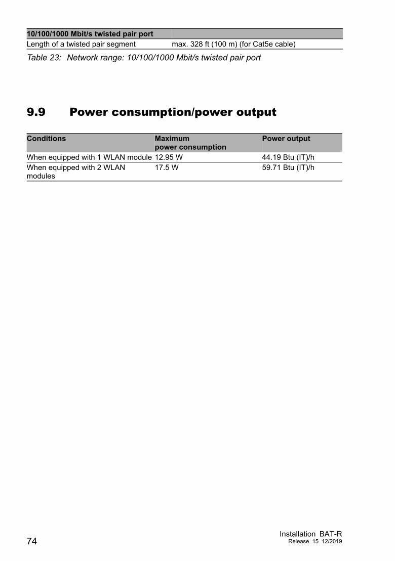
9.9 Power consumption/power output
10/100/1000 Mbit/s twisted pair portLength of a twisted pair segment max. 328 ft (100 m) (for Cat5e cable)
Table 23: Network range: 10/100/1000 Mbit/s twisted pair port
Conditions Maximumpower consumption
Power output
When equipped with 1 WLAN module 12.95 W 44.19 Btu (IT)/hWhen equipped with 2 WLAN modules
17.5 W 59.71 Btu (IT)/h
74Installation BAT-R
Release 15 12/2019
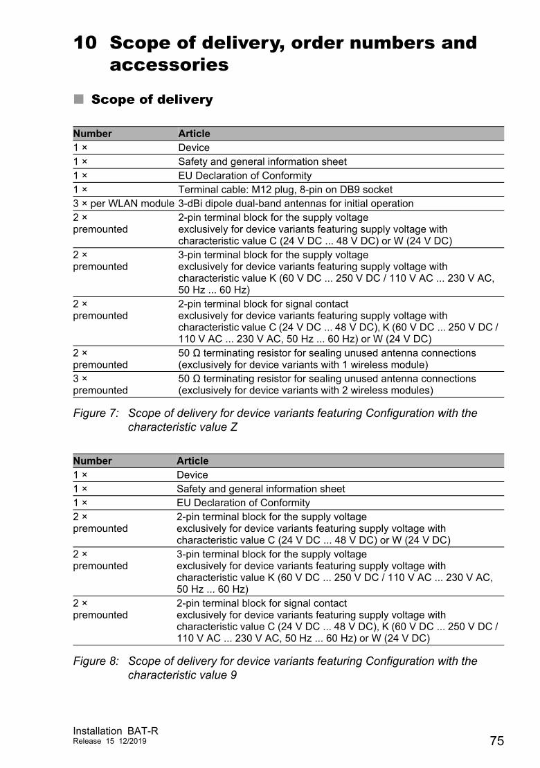
10 Scope of delivery, order numbers and accessories
Scope of delivery
Figure 7: Scope of delivery for device variants featuring Configuration with the characteristic value Z
Figure 8: Scope of delivery for device variants featuring Configuration with the characteristic value 9
Number Article1 × Device1 × Safety and general information sheet1 × EU Declaration of Conformity1 × Terminal cable: M12 plug, 8-pin on DB9 socket3 × per WLAN module 3-dBi dipole dual-band antennas for initial operation2 ×premounted
2-pin terminal block for the supply voltageexclusively for device variants featuring supply voltage with characteristic value C (24 V DC ... 48 V DC) or W (24 V DC)
2 ×premounted
3-pin terminal block for the supply voltageexclusively for device variants featuring supply voltage with characteristic value K (60 V DC ... 250 V DC / 110 V AC ... 230 V AC, 50 Hz ... 60 Hz)
2 ×premounted
2-pin terminal block for signal contactexclusively for device variants featuring supply voltage with characteristic value C (24 V DC ... 48 V DC), K (60 V DC ... 250 V DC / 110 V AC ... 230 V AC, 50 Hz ... 60 Hz) or W (24 V DC)
2 ×premounted
50 Ω terminating resistor for sealing unused antenna connections(exclusively for device variants with 1 wireless module)
3 ×premounted
50 Ω terminating resistor for sealing unused antenna connections(exclusively for device variants with 2 wireless modules)
Number Article1 × Device1 × Safety and general information sheet1 × EU Declaration of Conformity2 ×premounted
2-pin terminal block for the supply voltageexclusively for device variants featuring supply voltage with characteristic value C (24 V DC ... 48 V DC) or W (24 V DC)
2 ×premounted
3-pin terminal block for the supply voltageexclusively for device variants featuring supply voltage with characteristic value K (60 V DC ... 250 V DC / 110 V AC ... 230 V AC, 50 Hz ... 60 Hz)
2 ×premounted
2-pin terminal block for signal contactexclusively for device variants featuring supply voltage with characteristic value C (24 V DC ... 48 V DC), K (60 V DC ... 250 V DC / 110 V AC ... 230 V AC, 50 Hz ... 60 Hz) or W (24 V DC)
Installation BAT-RRelease 15 12/2019 75
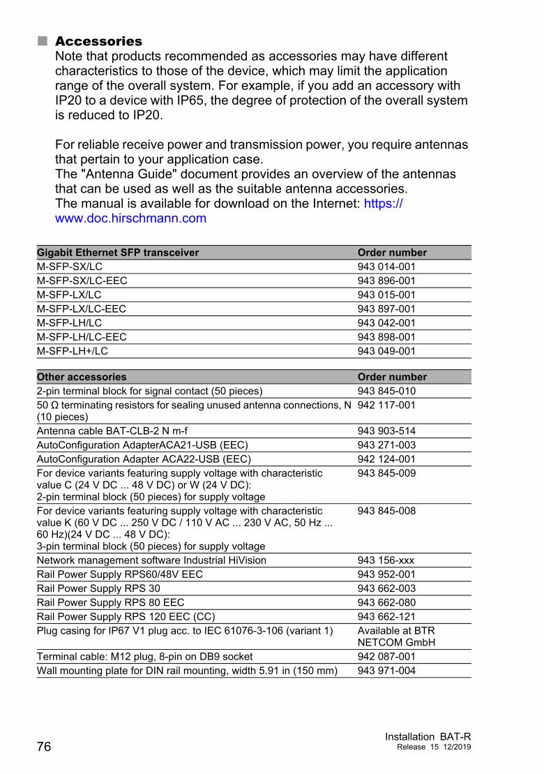
AccessoriesNote that products recommended as accessories may have different characteristics to those of the device, which may limit the application range of the overall system. For example, if you add an accessory with IP20 to a device with IP65, the degree of protection of the overall system is reduced to IP20. For reliable receive power and transmission power, you require antennas that pertain to your application case.The "Antenna Guide" document provides an overview of the antennas that can be used as well as the suitable antenna accessories.The manual is available for download on the Internet: https://www.doc.hirschmann.com
Gigabit Ethernet SFP transceiver Order numberM-SFP-SX/LC 943 014-001M-SFP-SX/LC-EEC 943 896-001M-SFP-LX/LC 943 015-001M-SFP-LX/LC-EEC 943 897-001M-SFP-LH/LC 943 042-001M-SFP-LH/LC-EEC 943 898-001M-SFP-LH+/LC 943 049-001
Other accessories Order number2-pin terminal block for signal contact (50 pieces) 943 845-01050 Ω terminating resistors for sealing unused antenna connections, N (10 pieces)
942 117-001
Antenna cable BAT-CLB-2 N m-f 943 903-514AutoConfiguration AdapterACA21-USB (EEC) 943 271-003AutoConfiguration Adapter ACA22-USB (EEC) 942 124-001For device variants featuring supply voltage with characteristic value C (24 V DC ... 48 V DC) or W (24 V DC):2-pin terminal block (50 pieces) for supply voltage
943 845-009
For device variants featuring supply voltage with characteristic value K (60 V DC ... 250 V DC / 110 V AC ... 230 V AC, 50 Hz ... 60 Hz)(24 V DC ... 48 V DC):3-pin terminal block (50 pieces) for supply voltage
943 845-008
Network management software Industrial HiVision 943 156-xxxRail Power Supply RPS60/48V EEC 943 952-001Rail Power Supply RPS 30 943 662-003Rail Power Supply RPS 80 EEC 943 662-080Rail Power Supply RPS 120 EEC (CC) 943 662-121Plug casing for IP67 V1 plug acc. to IEC 61076-3-106 (variant 1) Available at BTR
NETCOM GmbHTerminal cable: M12 plug, 8-pin on DB9 socket 942 087-001Wall mounting plate for DIN rail mounting, width 5.91 in (150 mm) 943 971-004
76Installation BAT-R
Release 15 12/2019
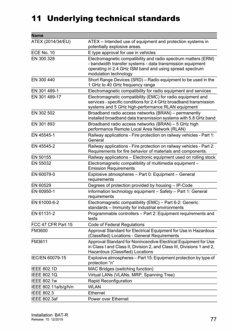
11 Underlying technical standards
NameATEX (2014/34/EU) ATEX – Intended use of equipment and protection systems in
potentially explosive areas.ECE No. 10 E type approval for use in vehiclesEN 300 328 Electromagnetic compatibility and radio spectrum matters (ERM)
- bandwidth transfer systems - data transmission equipment operating in 2.4 GHz ISM band and using spread spectrum modulation technology
EN 300 440 Short Range Devices (SRD) – Radio equipment to be used in the 1 GHz to 40 GHz frequency range
EN 301 489-1 Electromagnetic compatibility for radio equipment and servicesEN 301 489-17 Electromagnetic compatibility (EMC) for radio equipment and
services - specific conditions for 2.4 GHz broadband transmission systems and 5 GHz high-performance RLAN equipment
EN 302 502 Broadband radio access networks (BRAN) – permanently installed broadband data transmission systems with 5.8 GHz band
EN 301 893 Broadband radio access networks (BRAN) – 5 GHz high performance Remote Local Area Network (RLAN)
EN 45545-1 Railway applications - Fire protection on railway vehicles - Part 1: General
EN 45545-2 Railway applications - Fire protection on railway vehicles - Part 2: Requirements for fire behavior of materials and components.
EN 50155 Railway applications – Electronic equipment used on rolling stockEN 55032 Electromagnetic compatibility of multimedia equipment –
Emission RequirementsEN 60079-0 Explosive atmospheres – Part 0: Equipment – General
requirementsEN 60529 Degrees of protection provided by housing – IP-CodeEN 60950-1 Information technology equipment – Safety – Part 1: General
requirementsEN 61000-6-2 Electromagnetic compatibility (EMC) – Part 6-2: Generic
standards – Immunity for industrial environmentsEN 61131-2 Programmable controllers – Part 2: Equipment requirements and
testsFCC 47 CFR Part 15 Code of Federal RegulationsFM3600 Approval Standard for Electrical Equipment for Use in Hazardous
(Classified) Locations - General RequirementsFM3611 Approval Standard for Nonincendive Electrical Equipment for Use
in Class I and Class II, Division 2, and Class III, Divisions 1 and 2, Hazardous (Classified) Locations
IEC/EN 60079-15 Explosive atmospheres – Part 15: Equipment protection by type of protection “n”
IEEE 802.1D MAC Bridges (switching function)IEEE 802.1Q Virtual LANs (VLANs, MRP, Spanning Tree)IEEE 802.1w Rapid ReconfigurationIEEE 802.11a/b/g/h/n WLANIEEE 802.3 EthernetIEEE 802.3af Power over Ethernet
Installation BAT-RRelease 15 12/2019 77
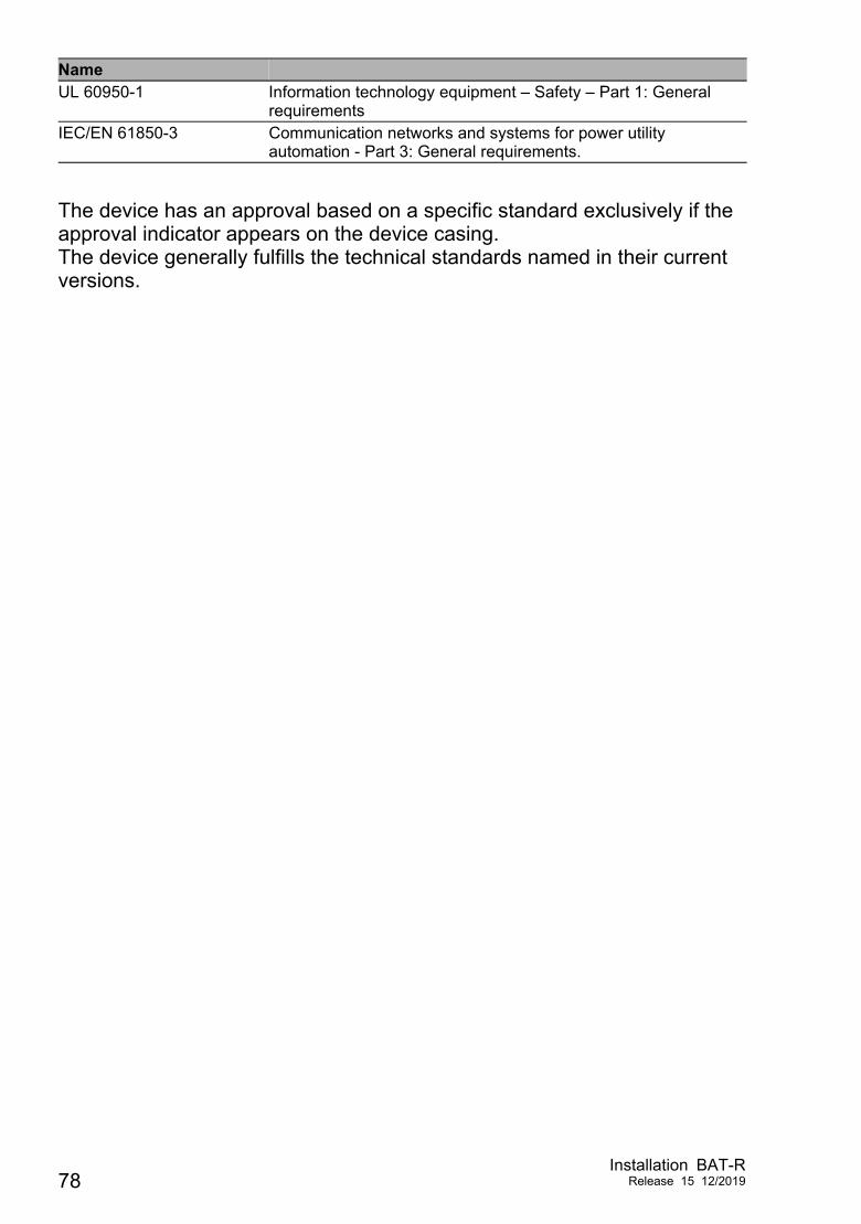
The device has an approval based on a specific standard exclusively if the approval indicator appears on the device casing.The device generally fulfills the technical standards named in their current versions.
UL 60950-1 Information technology equipment – Safety – Part 1: General requirements
IEC/EN 61850-3 Communication networks and systems for power utility automation - Part 3: General requirements.
Name
78Installation BAT-R
Release 15 12/2019

A Further support
Technical questions
For technical questions, please contact any Hirschmann dealer in your area or Hirschmann directly.
You find the addresses of our partners on the Internet at http://www.hirschmann.com.
A list of local telephone numbers and email addresses for technical support directly from Hirschmann is available at https://hirschmann-support.belden.com.
This site also includes a free of charge knowledge base and a software download section.
Hirschmann Competence Center
The Hirschmann Competence Center is ahead of its competitors on three counts with its complete range of innovative services:
Consulting incorporates comprehensive technical advice, from system evaluation through network planning to project planning.
Training offers you an introduction to the basics, product briefing and user training with certification.You find the training courses on technology and products currently available at http://www.hicomcenter.com.
Support ranges from the first installation through the standby service to maintenance concepts.
With the Hirschmann Competence Center, you decided against making any compromises. Our client-customized package leaves you free to choose the service components you want to use.
Internet:http://www.hicomcenter.com
Installation BAT-RRelease 15 12/2019 79