Embed Size (px)
Citation preview
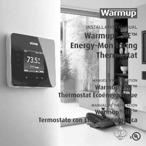
INSTALLATION MANUAL
Warmup® 3iE™Energy-Monitoring
Thermostat
MANUEL D’INSTALLATION
Warmup® 3iE™Thermostat Ecoénergétique
MANUAL DE INSTALACION
Warmup® 3iE™Termostato con Eficacia Energética
2
24/7 Technical hotline - Ligne d’assistance technique - Línea de asistencia técnica US 1.888.927.6333 / CA 1.888.592.7687
The 3iE thermostat is designed to aid in the comfort of your home by providing timed regulation of your Warmup floor heating system. The thermostat is designed to receive temperature input signals from the following sensors:
1. Air sensor located inside thermostat2. Floor sensor installed in floor to be heated (see Warmup heating product instructions for details)3. Optional 2nd sensor (either installed in floor or outside house)
The thermostat is not a safety device and should only be used with Warmup heating products. In order to avoid damaging your flooring the correct floor type should be selected during the thermostat programming process.
WARNING – Important safety noteThis product uses mains voltage electricity and work should only be carried out by a qualified electrician. You should always isolate the power supply before attempting to install or repair the 3iE thermostat. The thermostat should not be put into operation unless you are certain that the entire heating installation complies with current general safety requirements for electrical installations. Electrical installation to be in accordance with latest local electrical wiring code and appropriate Statutory Regulations.
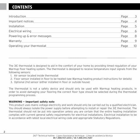
INTRODUCTIONCONTENTS
Introduction Page 3
Important notices Page 4
Installation Page 5
Electrical wiring Page 6
Powering up & error messages Page 8
Warranty Page 9
Operating your thermostat Page 10
24/7 Technical hotline - Ligne d’assistance technique - Línea de asistencia técnica US 1.888.927.6333 / CA 1.888.592.7687
3
INTRODUCTION
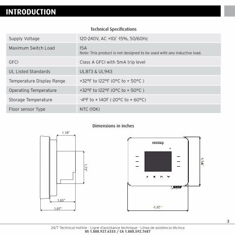
Technical Specifications
Supply Voltage 120-240V, AC +10/ -15%, 50/60Hz
Maximum Switch Load 15A Note: This product is not designed to be used with any inductive load.
GFCI Class A GFCI with 5mA trip level
UL Listed Standards UL873 & UL943
Temperature Display Range +32°F to 122°F (0°C to + 50°C )
Operating Temperature +32°F to 122°F (0°C to + 50°C )
Storage Temperature -4°F to + 140F (-20°C to + 60°C)
Floor sensor Type NTC (10K)
4.41”
1.97”
3.54”
1.18”
1.65”
1.73”
Dimensions (inch)
Dimensions in inches
4
24/7 Technical hotline - Ligne d’assistance technique - Línea de asistencia técnica US 1.888.927.6333 / CA 1.888.592.7687
FCC NoticeThis device complies with Part 15 of the FCC Rules. Operation is subject to the following two conditions: (1) this device may not cause harmful interference, and (2) this device must accept any interference received, including interference that may cause undesired operation.
Warning: Changes or modifications to this unit not expressly approved by the party responsible for compliance could void the user’s authority to operate the equipment.
NOTE: This equipment has been tested and found to comply with the limits for a Class B digital device, pursuant to Part 15 of the FCC Rules. These limits are designed to provide reasonable protection against harmful interference in a residential installation. This equipment generates, uses, and can radiate radio frequency energy and, if not installed and used in accordance with the instructions, may cause harmful interference to radio communications. However, there is no guarantee that interference will not occur in a particular installation. If this equipment does cause harmful interference to radio or television reception, which can be determined by turning the equipment off and on, the user is encouraged to try to correct the interference by one or more of the following measures:
– Reorient or relocate the receiving antenna.– Increase the separation between the equipment and receiver.– Connect the equipment into an outlet on a circuit different from that to which the receiver is
connected.- Consult the dealer or an experienced radio TV technician for help.
WET AREASInstall the thermostat a minimum of 5ft away from showers, tubs and other sources of splashing water.
IMPORTANT NOTICES
24/7 Technical hotline - Ligne d’assistance technique - Línea de asistencia técnica US 1.888.927.6333 / CA 1.888.592.7687
5
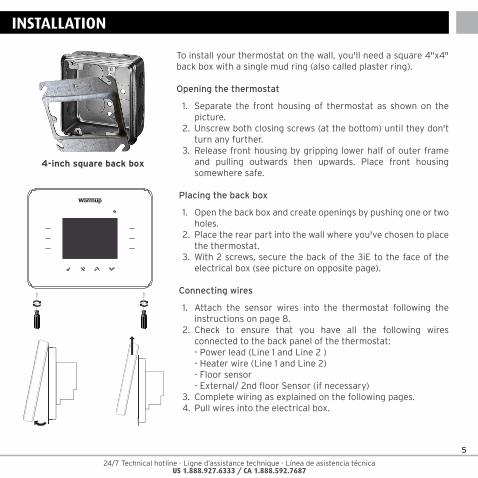
To install your thermostat on the wall, you'll need a square 4"x4" back box with a single mud ring (also called plaster ring).
Opening the thermostat
1. Separate the front housing of thermostat as shown on the picture.
2. Unscrew both closing screws (at the bottom) until they don't turn any further.
3. Release front housing by gripping lower half of outer frame and pulling outwards then upwards. Place front housing somewhere safe.
Placing the back box
1. Open the back box and create openings by pushing one or two holes.
2. Place the rear part into the wall where you've chosen to place the thermostat.
3. With 2 screws, secure the back of the 3iE to the face of the electrical box (see picture on opposite page).
Connecting wires
1. Attach the sensor wires into the thermostat following the instructions on page 8.
2. Check to ensure that you have all the following wires connected to the back panel of the thermostat:
- Power lead (Line 1 and Line 2 ) - Heater wire (Line 1 and Line 2) - Floor sensor - External/ 2nd floor Sensor (if necessary)3. Complete wiring as explained on the following pages.4. Pull wires into the electrical box.
INSTALLATION
4-inch square back box
6
24/7 Technical hotline - Ligne d’assistance technique - Línea de asistencia técnica US 1.888.927.6333 / CA 1.888.592.7687
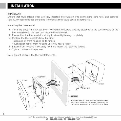
IMPORTANTEnsure that multi strand wires are fully inserted into twist-on wire connectors (wire nuts) and secured tightly. Any loose strands should be trimmed as they could cause a short-circuit.
Mounting the thermostat
1. Close the electrical back box by screwing the front part (already attached to the back module of the thermostat) onto the rear part installed into the wall.
2. Ensure that the thermostat is straight before tightening completely.4. Replace the thermostat's front housing; - align and sit front housing on to hinges, - push lower half of front housing until you hear a ‘click’. 5. Ensure front housing is securely fixed and insert the retaining screws.6. Tighten both retaining screws.
Note: Do not obstruct the thermostat’s vents.
INSTALLATION
24/7 Technical hotline - Ligne d’assistance technique - Línea de asistencia técnica US 1.888.927.6333 / CA 1.888.592.7687
7
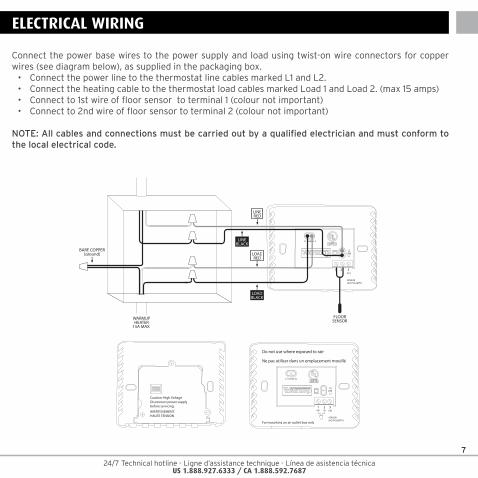
Connect the power base wires to the power supply and load using twist-on wire connectors for copper wires (see diagram below), as supplied in the packaging box.• ConnectthepowerlinetothethermostatlinecablesmarkedL1andL2.• ConnecttheheatingcabletothethermostatloadcablesmarkedLoad1andLoad2.(max15amps)• Connectto1stwireoffloorsensortoterminal1(colournotimportant)• Connectto2ndwireoffloorsensortoterminal2(colournotimportant)
NOTE: All cables and connections must be carried out by a qualified electrician and must conform to the local electrical code.
ELECTRICAL WIRING
Caution: High VoltageDisconnect power supplybefore servicing.
AVERTISSEMENT:HAUTE TENSION
For mounting on an outlet box only
1 2 3EXT
SENSOR (NO POLARITY)
L1-LOAD-L2
L2LINE
L1
Do not use where exposed to rain
Ne pas utiliser dans un emplacement mouillé
1 2 3EXT
SENSOR (NO POLARITY)
L1-LOAD-L2
L2LINE
L1LOADRED
LOADBLACK
LINEBLACK
LINERED
BARE COPPER(ground)
FLOORSENSORWARMUP
HEATER15A MAX.
8
24/7 Technical hotline - Ligne d’assistance technique - Línea de asistencia técnica US 1.888.927.6333 / CA 1.888.592.7687
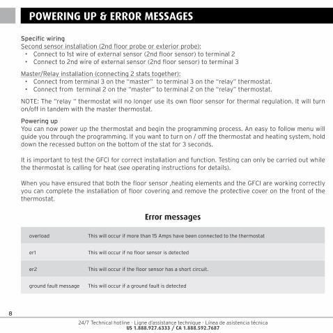
Specific wiringSecond sensor installation (2nd floor probe or exterior probe):• Connectto1stwireofexternalsensor(2ndfloorsensor)toterminal2• Connectto2ndwireofexternalsensor(2ndfloorsensor)toterminal3
Master/Relay installation (connecting 2 stats together):• Connectfromterminal3onthe“master”toterminal3onthe“relay”thermostat.• Connectfromterminal2onthe“master”toterminal2onthe“relay”thermostat.
NOTE:The“relay“thermostatwillnolongeruseitsownfloorsensorforthermalregulation.Itwillturnon/off in tandem with the master thermostat.
Powering upYou can now power up the thermostat and begin the programming process. An easy to follow menu will guide you through the programming. If you want to turn on / off the thermostat and heating system, hold down the recessed button on the bottom of the stat for 3 seconds.
It is important to test the GFCI for correct installation and function. Testing can only be carried out while the thermostat is calling for heat (see operating instructions for details).
When you have ensured that both the floor sensor ,heating elements and the GFCI are working correctly you can complete the installation of floor covering and remove the protective cover on the front of the thermostat.
POWERING UP & ERROR MESSAGES
Error messages
overload This will occur if more than 15 Amps have been connected to the thermostat
er1 This will occur if no floor sensor is detected
er2 This will occur if the floor sensor has a short circuit.
ground fault message This will occur if a ground fault is detected
24/7 Technical hotline - Ligne d’assistance technique - Línea de asistencia técnica US 1.888.927.6333 / CA 1.888.592.7687
9
WARRANTY
Warmup Inc warrants this product, to be free from defects in the workmanship or materials, under normal use and service, for a period of three (3) years from the date of purchase by the consumer. If at any time during the warranty period the product is determined to be defective, Warmup shall repair or replace it, at Warmup’s option.
If the product is defective, please either,
(I) return it, with a bill of sale or other dated proof of purchase, to the place from which you purchased it, or
(ii) contact Warmup. Warmup will determine whether the product should be returned, or replaced.
This warranty does not cover removal or reinstallation costs, and shall not apply if it is shown by Warmup that the defect or malfunction was caused by damage which occurred while the product was in the possession of a consumer.Warmup’s sole responsibility shall be to repair or replace the product within the terms stated above.
WARMUP SHALL NOT BE LIABLE FOR ANY LOSS OR DAMAGE OF ANY KIND, INCLUDING ANY INCIDENTAL OR CONSEQUENTIAL DAMAGES RESULTING, DIRECTLY OR INDIRECTLY, FROM ANY BREACH OF ANY WARRANTY, EXPRESS OR IMPLIED, OR ANY OTHER FAILURE OF THIS PRODUCT. THIS WARRANTY IS THE ONLY EXPRESS WARRANTY WARMUP MAKES ON THIS PRODUCT. THE DURATION OF ANY IMPLIED WARRANTIES, INCLUDING THE WARRANTIES OF MERCHANTABILITY AND FITNESS FOR A PARTICULAR PURPOSE, IS HEREBY LIMITED TO THE THREE-YEAR DURATION OF THIS WARRANTY.
This warranty does not affect your statutory rights.
PLEASE REGISTER YOUR WARMUP PRODUCT AT: www.warmup.com (USA) or www.warmup.ca (CANADA)
INSTALLATION GUARANTEE
TM
10
24/7 Technical hotline - Ligne d’assistance technique - Línea de asistencia técnica US 1.888.927.6333 / CA 1.888.592.7687
You can view or download the programming manual from our website at:
www.warmup.ca www.warmup.com
For more information about the 3iE, please also check www.3iethermostat.com
OPERATING YOUR THERMOSTAT
24/7 Technical hotline - Ligne d’assistance technique - Línea de asistencia técnica US 1.888.927.6333 / CA 1.888.592.7687
11
CONTENU
Le thermostat 3iE a été conçu pour assurer un confort thermique dans votre habitation. Programmable sur plusieurs plages horaires, il régule de façon précise les planchers chauffants électriques de Warmup.Ce thermostat est destiné à analyser et enregistrer les lectures de température transmises par les sondes suivantes :
1. Sonde d’air situé dans le thermostat2. Sonde de sol à installer dans le sol (voir le manuel d’installation du plancher chauffant électrique
Warmup pour plus de détails)3. Sonde supplémentaire (optionnel) (installée soit dans le sol soit à l’extérieur de l’habitation)
Le thermostat n’est pas un système de sécurité et doit seulement être utilisé avec les planchers chauffants électriques Warmup. Afin d’eviter d’endommager votre revêtement de sol, veillez à bien sélectionner le type de revêtement de sol installé lors de la programmation du thermostat.
ATTENTION – note de sécurité importante :Ce produit fonctionne avec l’alimentation électrique (courant) et l’installation doit être opérée par un électricien qualifié. Veillez à toujours isoler le thermostat du courant avant de l’installer ou de le réparer. Le thermostat ne doit être mis en route qu’après s’être assuré que le plancher chauffant électrique Warmup a été installé conformément aux normes et codes électriques en vigueur.
Introduction Page 12
Notes importantes Page 13
Installation Page 14
Branchement électrique Page 16
Mise en marche & messages d'erreur Page 17
Garantie Page 18
Programmer votre thermostat Page 19

12
24/7 Technical hotline - Ligne d’assistance technique - Línea de asistencia técnica US 1.888.927.6333 / CA 1.888.592.7687
INTRODUCTION
Spécifications Techniques
Tension nominale 120-240V, CA +10/ -15%, 50/60Hz
Charge maximale 15 Amp.Note: Ce produit ne doit pas être utilisé avec une charge inductive.
DDFT DDFT de classe A avec niveau de déclenchement 5mA
Certifié UL UL873 & UL943
Différentiel de température +32°F to 122°F (0°C to + 50°C )
Température opérationnelle +32°F to 122°F (0°C to + 50°C )
Température de stockage -4°F to + 140F (-20°C to + 60°C)
Type de sonde au sol NTC (10K)
4.41”
1.97”
3.54”
1.18”
1.65”
1.73”
Dimensions (inch)
Dimensions en pouces
24/7 Technical hotline - Ligne d’assistance technique - Línea de asistencia técnica US 1.888.927.6333 / CA 1.888.592.7687
13
Note FCCCet appareil est conforme à la Partie 15 des règlements de la FCC. Son fonctionnement est soumis aux deux conditions suivantes: (1) ce dispositif ne doit pas causer d’interférences nuisibles, et (2) cet appareil doit accepter toute interférence reçue, y compris les interférences qui peuvent provoquer un fonctionnement indésirable.Avertissement: Les changements ou modifications apportés à cette unité n’étant pas expressément approuvés par la partie responsable de la conformité pourrait annuler l’autorité de l’utilisateur de faire fonctionner l’équipement.
REMARQUE: Cet équipement a été testé et trouvé conforme aux limites pour un dispositif numérique de classe B, conformément à la Partie 15 des règlements de la FCC. Ces limites sont conçues pour fournir une protection raisonnable contre les interférences nuisibles dans une installation résidentielle. Cet équipement génère, utilise et peut émettre des fréquences radio et, s’il n’est pas installé et utilisé conformément aux instructions, peut causer des interférences nuisibles aux communications radio. Cependant, il n’existe aucune garantie que des interférences ne se produiront pas dans une installation particulière. Si cet équipement provoque des interférences nuisibles à la réception radio ou télévision, ce qui peut être déterminé en allumant et en éteignant, l’utilisateur est encouragé à essayer de corriger l’interférence par un ou plusieurs des mesures suivantes:• Réorienteroudéplacerl’antennederéception.• Augmentezladistanceentrel’équipementetlerécepteur.• Branchezl’appareildansuneprisesuruncircuitdifférentdeceluisurlequelestbranchélerécepteur.• Consulterlerevendeurouuntechnicienradioqualifiépourassistance.
ZONES HUMIDESInstallez le thermostat à un minimum de 5pi des douches, baignoires et autres sources d’eau.
NOTES IMPORTANTES
14
24/7 Technical hotline - Ligne d’assistance technique - Línea de asistencia técnica US 1.888.927.6333 / CA 1.888.592.7687
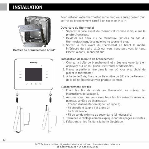
Pour installer votre thermostat sur le mur, vous aurez besoin d'un coffret de branchement carré à un socle de 4" x 4".
Ouverture du thermostat1. Séparez la face avant du thermostat comme indiqué sur la
photo ci-dessous.2. Dévissez les deux vis de fermeture (situées au bas du
thermostat) jusqu'à ce qu'elles ne tournent plus.3. Sortez la face avant du thermostat en tirant la moitié
inférieure du cadre extérieur vers vous puis vers le haut. Placez-la dans un endroit sûr.
Installation de la boîte de branchement1. Ouvrez la boîte de branchement et créez une ouverture en
appuyant sur un (ou plusieurs) trou(s) prédéssiné(s).2. Placez la partie arrière dans le mur où vous avez choisi de
placer le thermostat.3. A l'aide de 2 vis, fixez la partie arrière du 3iE à la partie avant
de la boîte électrique (voir photo ci-contre).
Raccordement des fils1. Fixez les fils de sonde au thermostat en suivant les
instructions de la page 8.2. Assurez-vous que vous avez tous les fils suivants reliés au
panneau arrière du thermostat: - Cordon d'alimentation (ligne 1 et ligne 2) - Fil chauffant (Ligne 1 et Ligne 2) - Le fil de sonde - Fil de sonde externe ou secondaire (si nécessaire)3. Terminez le câblage comme expliqué dans les pages suivantes.4. Faîtes entrer les fils dans la boîte électrique.
INSTALLATION
Coffret de branchement 4"x4"
24/7 Technical hotline - Ligne d’assistance technique - Línea de asistencia técnica US 1.888.927.6333 / CA 1.888.592.7687
15
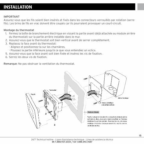
IMPORTANTAssurez-vous que les fils soient bien insérés et fixés dans les connecteurs verrouillés par rotation (serre-fils). Les brins de fils en vrac doivent être coupés car ils pourraient provoquer un court-circuit.
Montage du thermostat1. Fermez la boîte de branchement électrique en vissant la partie avant (déjà attachée au module arrière
du thermostat) sur la partie arrière installée dans le mur.2. Assurez-vous que le thermostat soit bien vertical avant de serrer complètement.3. Replacez la face avant du thermostat: - Alignez et positionnez-la sur les charnières, - Poussez la partie inférieure jusqu'à ce que vous entendiez un «clic».5. Assurez-vous que la face avant soit bien fixée et insérez les vis de fixation.6. Serrez les deux vis de fixation.
Remarque: Ne pas obstruer la ventilation du thermostat.
INSTALLATION
16
24/7 Technical hotline - Ligne d’assistance technique - Línea de asistencia técnica US 1.888.927.6333 / CA 1.888.592.7687
BRANCHEMENT ELECTRIQUE
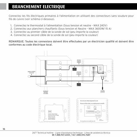
Connectez les fils électriques primaires à l'alimentation en utilisant des connecteurs sans soudure pour fils de cuivre (voir schéma ci-dessous).
1. Connectez le thermostat à l’alimentation (Sous tension et neutre – MAX 240V)2. Connectez aux planchers chauffants (Sous tension et Neutre – MAX 3600W/ 15 A)3. Connectez au premier câble de la sonde de sol (peu importe la couleur)4. Connectez au second câble de la sonde de sol (peu importe la couleur)
REMARQUE: Toutes les connexions doivent être effectuées par un électricien qualifié et doivent être conformes au code électrique local.
Caution: High VoltageDisconnect power supplybefore servicing.
AVERTISSEMENT:HAUTE TENSION
For mounting on an outlet box only
1 2 3EXT
SENSOR (NO POLARITY)
L1-LOAD-L2
L2LINE
L1
Do not use where exposed to rain
Ne pas utiliser dans un emplacement mouillé
1 2 3EXT
SENSOR (NO POLARITY)
L1-LOAD-L2
L2LINE
L1LOADRED
LOADBLACK
LINEBLACK
LINERED
BARE COPPER(ground)
FLOORSENSORWARMUP
HEATER15A MAX.
24/7 Technical hotline - Ligne d’assistance technique - Línea de asistencia técnica US 1.888.927.6333 / CA 1.888.592.7687
17
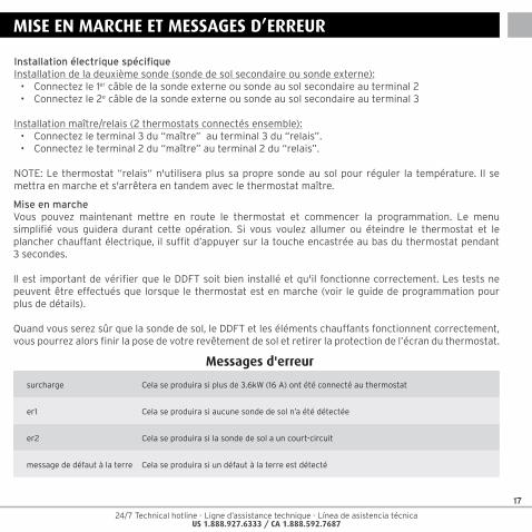
Installation électrique spécifiqueInstallation de la deuxième sonde (sonde de sol secondaire ou sonde externe):• Connectezle1er câble de la sonde externe ou sonde au sol secondaire au terminal 2 • Connectezle2e câble de la sonde externe ou sonde au sol secondaire au terminal 3
Installation maître/relais (2 thermostats connectés ensemble):• Connectezleterminal3du“maître”auterminal3du“relais”.• Connectezleterminal2du“maître”auterminal2du“relais”.
NOTE:Lethermostat“relais“n'utiliseraplussapropresondeausolpourréguler latempérature. Ilsemettra en marche et s'arrêtera en tandem avec le thermostat maître.
Mise en marcheVous pouvez maintenant mettre en route le thermostat et commencer la programmation. Le menu simplifié vous guidera durant cette opération. Si vous voulez allumer ou éteindre le thermostat et le plancher chauffant électrique, il suffit d’appuyer sur la touche encastrée au bas du thermostat pendant 3 secondes.
Il est important de vérifier que le DDFT soit bien installé et qu'il fonctionne correctement. Les tests ne peuvent être effectués que lorsque le thermostat est en marche (voir le guide de programmation pour plus de détails).
Quand vous serez sûr que la sonde de sol, le DDFT et les éléments chauffants fonctionnent correctement, vous pourrez alors finir la pose de votre revêtement de sol et retirer la protection de l’écran du thermostat.
MISE EN MARCHE ET MESSAGES D’ERREUR
Messages d'erreur
surcharge Cela se produira si plus de 3.6kW (16 A) ont été connecté au thermostat
er1 Cela se produira si aucune sonde de sol n’a été détectée
er2 Cela se produira si la sonde de sol a un court-circuit
message de défaut à la terre Cela se produira si un défaut à la terre est détecté
18
24/7 Technical hotline - Ligne d’assistance technique - Línea de asistencia técnica US 1.888.927.6333 / CA 1.888.592.7687
GARANTIE
Warmup Inc garantit ce produit d'être exempt de défauts matériels ou de fabrication, en utilisation et fonctionnement normal, pour une période de trois (3) ans à compter de la date d'achat. A tout moment au cours de la période de garantie si le produit est jugé défectueux, Warmup le réparera ou le remplacera, à sa propre discrétion.
Si le produit est défectueux, veuillez soit,
(I) le retourner, avec une facture ou toute autre preuve d'achat datée, à l'endroit où vous l'avez acheté, ou
(ii) communiquer avec Warmup. Warmup déterminera si le produit doit être retourné ou remplacé.
Cette garantie ne couvre pas les frais de déménagement ou de réinstallation, et ne s'appliquera pas s'il est démontré par Warmup que le défaut de fonctionnement a été causé par détérioration qui a eu lieu alors que le produit était en la possession du consommateur. La seule responsabilité de Warmup est de réparer ou de remplacer le produit dans les conditions énoncées ci-dessus.
WARMUP NE SERA TENU RESPONSABLE POUR TOUT DOMMAGE OU PERTE DE QUELQUE NATURE QUE CE SOIT, Y COMPRIS LES DOMMAGES DIRECTS OU INDIRECTS RÉSULTANT, DIRECTEMENT OU INDIRECTEMENT D'UNE VIOLATION DE TOUTE GARANTIE, EXPRIMEE OU IMPLICITE OU DE TOUTE AUTRE DÉFAILLANCE DE CE PRODUIT. CETTE GARANTIE EST LA SEULE GARANTIE EXPRESSE WARMUP SUR CE PRODUIT. LA DURÉE DE TOUTE GARANTIE IMPLICITE, Y COMPRIS LES GARANTIES DE QUALITÉ MARCHANDE ET D'ADAPTATION À UN USAGE PARTICULIER, EST LIMITÉE À LA PÉRIODE DE TROIS ANS DE LA PRÉSENTE GARANTIE.
Cette garantie n'affecte pas vos droits statutaires.VEUILLEZ ENREGISTRER VOTRE PRODUIT CHAUFFANT A:www.warmup.com ou www.warmup.ca
GARANTIEINSTALLATIONGUARANTEE
TM
INSTALLATION GUARANTEE
TM
24/7 Technical hotline - Ligne d’assistance technique - Línea de asistencia técnica US 1.888.927.6333 / CA 1.888.592.7687
19
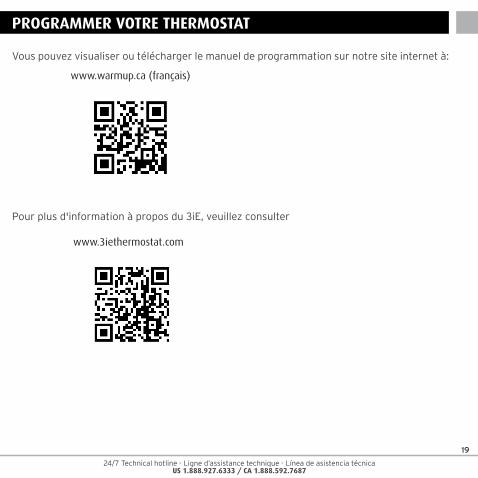
Vous pouvez visualiser ou télécharger le manuel de programmation sur notre site internet à:
www.warmup.ca (français)
Pour plus d'information à propos du 3iE, veuillez consulter
www.3iethermostat.com
PROGRAMMER VOTRE THERMOSTAT
20
24/7 Technical hotline - Ligne d’assistance technique - Línea de asistencia técnica US 1.888.927.6333 / CA 1.888.592.7687
CONTENIDO
El termostato 3iE™ ha sido diseñado para brindar confort a su hogar al facilitar el control de temperatura de su sistema de calefacción por suelo radiante Warmup. El termostado ha sido fabricado para recibir señales de temperatura de los sensores a listados continuación:
1. Sensor de ambiente ubicado en el interior del termostato2. Sensor de temperatura de suelo instalado bajo el revestimiento (Ver las instrucciones del termostato
para más detalles) 3. Segundo sensor opcional (ya sea instalado en el suelo o en exteriores)
Importante: El termostato no es un dispositivo de seguridad y por lo tanto su uso debe estar limitado a los productos de calefacción por suelo radiante Warmup. Durante el proceso de programación del termostato, es importante elegir el tipo de suelo correcto, con el fin de evitar daños en el revestimiento de éste último.
ADVERTENCIA– nota importante sobre seguridadNo se debe accionar el termostato antes de haber verificado que toda la instalación cumple con los requisitos vigentes de seguridad general para instalaciones eléctricas. Aísle la fuente de alimentación antes de realizar cualquier instalación o trabajo de mantenimiento en esta unidad de control y sus componentes asociados. Solamente personal competente (electricistas cualificados) deberán instalar esta unidad de control y los componentes asociados. La instalación eléctrica deberá realizarse de acuerdo con las Normativas Estatutarias aplicables más recientes.
Introducción Page 21
Notas importantes Page 22
Assemblea del conducto a la sonda Page 23
Instalación Page 24
Conexión eléctrica Page 25
Encendido & mensajes de error Page 26
Garantía Page 27
24/7 Technical hotline - Ligne d’assistance technique - Línea de asistencia técnica US 1.888.927.6333 / CA 1.888.592.7687
21
INTRODUCCION
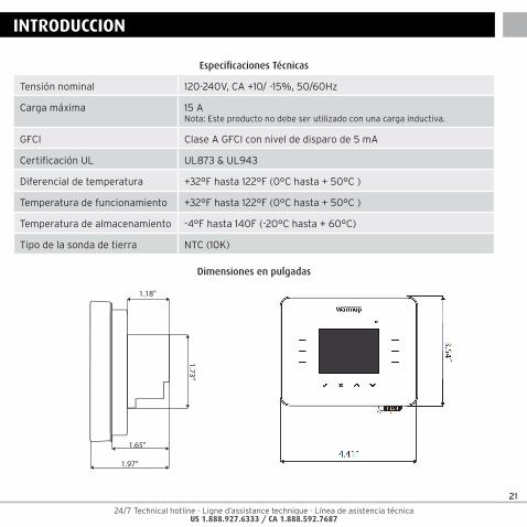
Especificaciones Técnicas
Tensión nominal 120-240V, CA +10/ -15%, 50/60Hz
Carga máxima 15 ANota: Este producto no debe ser utilizado con una carga inductiva.
GFCI Clase A GFCI con nivel de disparo de 5 mA
Certificación UL UL873 & UL943
Diferencial de temperatura +32°F hasta 122°F (0°C hasta + 50°C )
Temperatura de funcionamiento +32°F hasta 122°F (0°C hasta + 50°C )
Temperatura de almacenamiento -4°F hasta 140F (-20°C hasta + 60°C)
Tipo de la sonda de tierra NTC (10K)
4.41”
1.97”
3.54”
1.18”
1.65”
1.73”
Dimensions (inch)
Dimensiones en pulgadas
22
24/7 Technical hotline - Ligne d’assistance technique - Línea de asistencia técnica US 1.888.927.6333 / CA 1.888.592.7687
Aviso de la FCCEste dispositivo cumple con la Parte 15 de las Normas de la FCC. La operación está sujeta a las siguientes dos condiciones: (1) este dispositivo no puede causar interferencias perjudiciales y (2) este dispositivo debe aceptar cualquier interferencia recibida, incluyendo interferencias que puedan causar un funcionamiento no deseado.
Advertencia: Los cambios o modificaciones a esta unidad no aprobados expresamente por la parte responsable del cumplimiento podría anular la autoridad del usuario para operar el equipo.
NOTA: Este equipo ha sido probado y cumple con los límites para un dispositivo digital de Clase B, de conformidad con la Parte 15 del Reglamento de la FCC. Estos límites están diseñados para proporcionar una protección razonable contra interferencias perjudiciales en una instalación residencial. Este equipo genera, utiliza y puede irradiar energía de radiofrecuencia y, si no se instala y utiliza de acuerdo con las instrucciones, puede causar interferencias en las comunicaciones de radio. Sin embargo, no hay garantía de que no se produzcan interferencias en una instalación particular. Si este equipo causa interferencias perjudiciales en la recepción de radio o televisión, lo cual puede ser determinada girando el equipo apagado y, se recomienda al usuario que intente corregir la interferencia mediante una o más de las siguientes medidas:
• Reorientaroreubicarlaantenareceptora.• Aumentarlaseparaciónentreelequipoyelreceptor.• Conectarelequipoaun tomacorrienteenuncircuitodiferentedeaquelalqueestáconectadoel
receptor.• Consultealdistribuidoroauntécnicodetelevisiónenradioparapedirayuda.
ÁREAS MOJADASInstale el termostato a un mínimo de 5 pies de distancia de las duchas, tinas y otras fuentes de salpicaduras de agua.
NOTAS IMPORTANTES
24/7 Technical hotline - Ligne d’assistance technique - Línea de asistencia técnica US 1.888.927.6333 / CA 1.888.592.7687
23
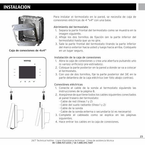
Para instalar el termostato en la pared, se necesita de caja de conexiones eléctricas de 4 "x4" con una base.
Abrimiento del termostato1. Separa la parte frontal del termostato como se muestra en la
imagen siguiente.2. Afloje los dos tornillos de fijación (en la parte inferior del
termostato) hasta que ya no gire.3. Sale la parte frontal del termostato tirando la parte inferior
del marco exterior hacia usted y luego hacia arriba. Colóquelo en un lugar seguro.
Instalación de la caja de conexiones1. Abra la caja de conexiones y crea una abertura pulsando uno
(o varios) orificio(s) pre-estirado(s).2. Coloque la parte posterior en la pared a donde se va a colocar
el termostato.3. Con uso de dos tornillos, fije la parte posterior del 3iE en la
parte delantera de la caja eléctrica (ver foto abajo contras).
Conexiónes eléctricas1. Conecte el cable de la sonda al termostato siguiendo las
instrucciones de la página 8.2. Asegúrese de que tiene todos los cables siguientes conectados
al panel trasero del termostato: - Cable de red (líneas 1 y 2) - Cable del suelo radiante (línea 1 y 2) - Cable de la sonda - Cable de la sonda externa o secundaria (si es necesario)3. Complete el cableado como se explica en las páginas
siguientes.4. Hace entrar los cables en la caja de conexiones.
INSTALACION
Caja de conexiones de 4x4"
24
24/7 Technical hotline - Ligne d’assistance technique - Línea de asistencia técnica US 1.888.927.6333 / CA 1.888.592.7687
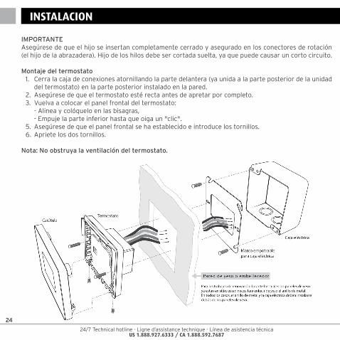
IMPORTANTEAsegúrese de que el hijo se insertan completamente cerrado y asegurado en los conectores de rotación (el hijo de la abrazadera). Hijo de los hilos debe ser cortada suelta, ya que puede causar un corto circuito.
Montaje del termostato1. Cerra la caja de conexiones atornillando la parte delantera (ya unida a la parte posterior de la unidad
del termostato) en la parte posterior instalado en la pared.2. Asegúrese de que el termostato esté recta antes de apretar por completo.3. Vuelva a colocar el panel frontal del termostato: - Alinea y colóquelo en las bisagras, - Empuje la parte inferior hasta que oiga un "clic".5. Asegúrese de que el panel frontal se ha establecido e introduce los tornillos.6. Apriete los dos tornillos.
Nota: No obstruya la ventilación del termostato.
INSTALACION
24/7 Technical hotline - Ligne d’assistance technique - Línea de asistencia técnica US 1.888.927.6333 / CA 1.888.592.7687
25
CONNEXION ELECTRICA
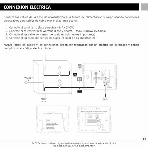
Conecte los cables de la base de alimentación a la fuente de alimentación y carga usando conectores enroscables para cables de cobre (ver el diagrama abajo).
1. Conecte al suministro (fase y neutral – MAX 240V)2. Conecte al calefactor (es) Warmup (Fase y neutral – MAX 3600W/ 16 Amps)3. Conecte al 1er cable del sensor de suelo (el color no es importante)4. Conecte al 2o cable del sensor de suelo (el color no es importante)
NOTA: Todos los cables y las conexiones deben ser realizados por un electricista calificado y deben cumplir con el código eléctrico local.
Caution: High VoltageDisconnect power supplybefore servicing.
AVERTISSEMENT:HAUTE TENSION
For mounting on an outlet box only
1 2 3EXT
SENSOR (NO POLARITY)
L1-LOAD-L2
L2LINE
L1
Do not use where exposed to rain
Ne pas utiliser dans un emplacement mouillé
1 2 3EXT
SENSOR (NO POLARITY)
L1-LOAD-L2
L2LINE
L1LOADRED
LOADBLACK
LINEBLACK
LINERED
BARE COPPER(ground)
FLOORSENSORWARMUP
HEATER15A MAX.
26
24/7 Technical hotline - Ligne d’assistance technique - Línea de asistencia técnica US 1.888.927.6333 / CA 1.888.592.7687
Instalación eléctrica especialInstalación del sensor de Segunda (2 ª planta de la sonda o la sonda exterior):• Conectaraprimeracabledesensorexterno/sensordela2ªplantaalaterminal2• Conectarconelhilodelsegundosensorexterno/sensordela2ªplantaalaterminal3
Maestro / Relevo de la instalación (conexión de 2 stats juntos):• Conectelaterminal3enel“maestro”alaterminal3enel“relevo”deltermostato.• Conectelaterminal2enel“maestro”alaterminal2enel“relevo”deltermostato.
NOTE: The “relay “ thermostat will no longer use it’s own floor sensor for thermal regulation. It will turn/off in tandem with the master thermostat.
Encendido del termostatoAhora puede encender el termostato y comenzar el proceso de programación. Un menú fácil de seguir lo guiará a través del proceso. Si desea encender o apagar el termostato y el sistema de calefacción, a continuación mantenga pulsado el botón empotrado en la parte inferior del termostato durante 3 segundos.
Es importante probar el GFCI para una instalación correcta y un buen funcionamiento. Las pruebas sólo pueden llevarse a cabo mientras el termostato activa la calefacción (ver instrucciones de uso para más detalles).
Cuando se haya asegurado de que tanto el sensor de piso como el GFCI y los elementos de calefacción funcionan correctamente, puede completar la instalación del revestimiento del suelo y puede remover la lámina protectora de pantalla.
ENCENDIDO Y MENSAJES DE ERROR
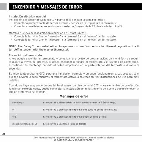
Mensajes de error
sobrecarga Esto ocurrirá si el termostato ha sido conectado a más de 3.6W (16 Amps)
er1 Esto ocurrirá si el sensor de temperatura del suelo no puede ser detectada
er2 Esto ocurrirá si el sensor de temperatura tiene un corto circuito
mensaje de falla de GFCI Esto ocurrirá si una falla a tierra se detecta

24/7 Technical hotline - Ligne d’assistance technique - Línea de asistencia técnica US 1.888.927.6333 / CA 1.888.592.7687
27
GARANTIA
Warmup Inc. garantiza que este producto está libre de defectos en materiales y mano de obra bajo uso normal y, por un período de tres (3) años a partir de la fecha de compra. En cualquier momento durante el periodo de garantía si el producto es defectuoso, Warmup se reparará o reemplazará, a su discreción.
Si el producto es defectuoso, por favor, o bien,
(I) regresa con un recibo o comprobante de la compra otra, donde lo compró, o
(Ii) póngase en contacto con Warmup. Warmup determinará si el producto debe ser devuelto o reemplazado.
Esta garantía no cubre los gastos de mudanza o reubicación, y no se aplicarán si se demuestra que el mal funcionamiento del suelo radiante estaba causado por daños que ocurrieron mientras el producto estaba en posesión del consumidor. La responsabilidad exclusiva de Warmup es para reparar o reemplazar el producto en las condiciones descritas anteriormente.
WARMUP NO SE HACE RESPONSABLE POR CUALQUIER PERDIDA O DAÑO DE NINGÚN TIPO, INCLUYENDO DAÑOS DIRECTOS O CONSECUENCIA DIRECTA O INDIRECTAMENTE POR EL INCUMPLIMIENTO DE LAS GARANTÍAS, EXPRESAS O IMPLÍCITAS, O CUALQUIER OTRA FALLA DE ESTE PRODUCTO. ESTA ES LA ÚNICA GARANTÍA EXPRESA DE ESTE PRODUCTO WARMUP. LA DURACIÓN DE LAS GARANTÍAS IMPLÍCITAS, INCLUIDAS LAS GARANTÍAS DE COMERCIALIZACIÓN Y APTITUD PARA UN PROPÓSITO PARTICULAR, SE LIMITA A LA DURACIÓN DE TRES AÑOS DE ESTA GARANTÍA.Esta garantía no afecta sus derechos legales.
POR FAVOR REGISTRE SU PRODUCTO DE SUELO RADIANTE EN:www.warmup.com o www.warmup.ca
Garantia
TM
GARANTÍA DE INSTALACIÓN
Consulte la página 10 para obtener instrucciones en inglés para descargar el manual de programación
28
24/7 Technical hotline - Ligne d’assistance technique - Línea de asistencia técnica US 1.888.927.6333 / CA 1.888.592.7687
Contacts
Warmup Inc52 Federal RoadUnit 1FDanbury, CT 06810USA
T: 888-927-6333F: [email protected]
4 Robert Speck ParkwaySuite 1500,Mississauga, ON L4Z 1S1Canada
T: 888-5-WARMUP (92-7687)T: +1-905-990-2075F: +1-905-990-1732Email: [email protected]