Embed Size (px)
DESCRIPTION
Installation manual for UPP double containment piping for hydrocarbons applications
Citation preview

protecting your liquid assets
PRODUCT INSTALLATION MANUAL
ContentsSection Title Page
1 Transport, Loading and Storage 21.1 Transit, on-loading and off-loading 21.2 Storage on site 21.3 Summary of rules 31.4 Uncoiling Pipe 3
2 Site Preparation 42.1 Getting started 42.2 Digging trenches and bedding 4
3 Installation Instructions 53.1 Site installation overview 63.2 Electrofusion method - Coupling two primary pipes 83.3 Electrofusion method - Primary pipe to a non-fusion fi tting 93.4 Electrofusion method - Primary pipe to a fusion fi tting 103.5 Electrofusion preparation details 113.6 Welding - overview 133.7 Installing a UPP polyethylene tank chamber 243.8 Installing a UPP polyethylene dispenser sump 263.9 Installing a UPP mechanical entry seal - (Holesaw/Seal compatability chart) 283.10 Installing a UPP electrofusion entry seal 293.11 UPP electrofusion seal options 303.12 Installing a UPP electrofusion FRP entry seal on a single wall tank sump 343.13 Installing a UPP electrofusion FRP entry seal on a double wall tank sump 373.14 Installing a UPP access cover 403.15 Electrofusion method - Secondary containment (double wall) 90° elbow 423.16 Electrofusion method - Secondary containment (double wall) Tee 43
4 System Integrity Testing Instructions 44
5 Tightness testing 465.1 Pressure testing 475.2 Vacuum testing 485.3 Pressure line testing at maximum operating pressure 48
6 Modifi cation And Repair Of UPP Sites 52
7 Pipe Re-fi t Through Ducts 54
8 Water Hammer Effects 56
9 Flow Loss Rates 57
10 Electrostatic Safety 59
11 Frequently Asked Questions 62
12 Safety 66
13 Notes 67

2
protecting your liquid assets
1.1 Transit, on-loading and off-loading
Although UPP polyethylene pipe and fi ttings are extremely hard wearing and resilient, it is important to handle and store them with care to prevent scuffi ng or gouging. Any damaged pipes may need to be rejected and not installed. (See ‘transit, loading and storage and storage - summary of rules’ on next page for details on what constitutes a damaged length of pipe)
• UPP products should be transported in a fl at-bedded vehicle, free from sharp objects and projections. Wide polypropylene slings must be used when lifting pipe crates by crane. Avoid using chains, hooks or hawsers. A spreading beam should be used when lifting crates containing pipe lengths greater than 6m (19ft 8”)
• Allow for a slight bending of the pipe crates when on and off-loading
• Standard 6m (19ft 8”) crates may be moved using a forklift. A side loader fi tted with a minimum of four supporting forks should be used for longer lengths. Otherwise use a crane fi tted with a spreader beam
• When using a forklift to on or off-load coils, the forks should be covered to avoid damage to the coiled pipe
1.2 Storage on site
• Individual pipe lengths should be stacked not more than 1m high (3ft) with the bottom layer fully restrained by wedges. Where possible the bottom layer of pipes should be laid on timber battens at 1m (3ft) centres to avoid any damage from sharp objects lying on the ground
• Pipe crates should be stored on clear, level ground and should never be stacked more than three crates high
• Coils should be stored on fi rm level ground that has suitable protection for the bottom of the coil. Stacked coils should never exceed three coils high. Individual coils should be stacked fl at. If stored on edge, they must be secured against a properly anchored support and stored like this for a short period of time only, particularly in warm weather conditions
• Badly stacked coils and pipe lengths can slip causing personal injury or damage to the product. Facilities for safe lifting and moving must be available
• Pipes are supplied with distinctive coloured end caps to prevent entry of any contamination. These end caps must be kept in place during storage
• UPP fi ttings - all electrofusion fi ttings are packed in heat-sealed polyethylene bags and delivered in cardboard cartons. Fittings should be stored in their packaging and in a dry area, away from direct sunlight, until ready for use. This is particularly important for electrofusion fi ttings. These must be kept in their packaging until ready for use to prevent any contamination or oxidisation
1. TRANSPORT, LOADING AND STORAGE

UIM
-V1.00.11.04
3
1.3 Summary of rules
Always Never• Store pipes on fl at, fi rm level ground
able to withstand the weight of pipes and lifting equipment
• Keep pipe and fi ttings well away from sharp objects such as fl ints and other site debris
• Use wide, non-metallic slings when lifting pipe
• Exercise special care when handling pipe in wet or frosty conditions. Use gloves for additional grip
• Keep protective packaging intact until pipe or fi ttings are required for use
• Keep both pipe and fi ttings out of direct sunlight or intense heat until ready to use
• Ensure lifting and storage points are evenly spaced
• Reject pipe if surface damage is excessive. Minor abrasions can be ignored
• Light abrasion handling damage, limited to a single area between a set of tapes less than 5mm (3/16”) wide is permitted
• Expose pipe or fi ttings to prolonged direct sunlight or excessive temperatures
• Throw, drop, drag or roll individual pipes, bundles or fi ttings as this can cause damage or subsequent leakage
• Use metal slings or chains when handling pipe
• Stack pipe more than three coils or three bundles high
1.4 Uncoiling pipe
• Take care when releasing pipe from the coil as the pipe can straighten with considerable force. It is also important to let the pipe rest out of its coiled state for about eight hours. High ambient temperatures can reduce this “layout” time and low temperatures may increase it. Pipe can be laid in its fi nal position to “relax” before connecting up
• You need at least two people to uncoil and cut the pipe. The coil is taped up in layers to make it easier to uncoil at manageable intervals
• The area in which the pipe is uncoiled on site must be clear, safe and free of sharp objects
• Remove the tape around the tail end on the outer winding and secure this end
• With the coil in the vertical position, roll the coil out cutting and removing tape as you fi nd it (ensuring to release only the next turn of pipe in the coil)
• Do not drag the pipe
• The natural curves from coiling can be used to change pipe direction and bags of sand, pea shingle or stakes can be used to hold it in place until it is ready for connecting
• One person should hold the pipe whilst another cuts it to the desired length
• The cut ends will have a prominent hook that can be partially removed when weight is placed on it (bags of sand or pea shingle). Or, the hook end can be used to your advantage when turning direction into a chamber or pump sump

4
protecting your liquid assets
2.1 Getting started
Dispenser mounting frames, offset-fi ll and vent frames should be positioned fi rst and fi rmly fi xed at their fi nal correct level to ensure that all pipe work can be laid with a continuous fall back to the tank.
2.2 Digging trenches and bedding
• It is important to construct proper trenches before laying UPP pipe. Trenches should be wide and deep enough to comfortably allow pipe runs, recommended spacing and backfi ll materials.
• Recommended burial depth of UPP pipe is a minimum of 300mm (12”)
• All trenches should be sloped back towards the storage tanks with a recommended gradient of 1:100
• Vapour return lines must have a slope of 1/4” per foot and never less than 1/8” per ft back towards the tank farm, unless in-line joints such as elbows are to be used
• Trench corners should be radiused to 1.5m (5ft)
• A recommended 15cm (6”) bed of backfi ll material should be laid underneath the pipe prior to installation and there must never be voids under or around the pipe. Acceptable backfi ll materials are:
•Well-rounded pea gravel with a maximum particle size not exceeding 20mm (¾”). No more than 3% of particles should pass through a 3.5mm (1/8”) screen
•Crushed rock with a maximum particle size not exceeding 16mm (5/8”). No more than 3% of particles should pass through a 3.5mm (1/8”) screen
•Well-graded sand with a maximum particle size not exceeding 3.5mm (1/8”)
• The bed should be laid so that the pipe will not dip or sag when it is installed
• Underground pipe runs may be continuous or have electrofusion welded joints. Any mechanical joints or compression fi ttings must be located within a containment chamber or sump
• UPP pipe exceeding 12m (39ft) should be laid in a series of large snake-like curves and not in straight lines. Uncoiled pipe, when laid, will settle in a natural curve
• Generally any thermal expansion will be accounted for by following our guidelines for spacing, backfi lling and ensuring runs are not dead straight
• Pipes should be separated from each other by at least the diameter of the largest pipe
• If pipe-runs cross each other they must be separated by at least as much backfi ll material as the diameter of the largest pipe or protected using at least 25mm (1”) of styrofoam
• If used above ground, UPP pipe should be protected against mechanical, climatic, UV and fi re damage by wrapping it in radiation or thermal shielding tape. Additional supports and anchor points may also be required
2. SITE PREPARATION

UIM
-V1.00.11.04
5
3. INSTALLATION INSTRUCTIONS
This section provides practical information regarding the installation of all parts of the UPP system.
Electrofusion, or welding by electrical heating, lies at the heart of the UPP system and helps to create one homogenous and permanently leak tight system.
PetroTechnik 230 volt and 115 volt Welding Units have been designed to supply the exact, controlled electrical energy necessary to fuse two UPP products together and to provide complete safety on site. The resultant heat causes the pipe and joint surfaces to melt and fuse. Once electrofusion has taken place, the assembly is left to cool while the polyethylene solidifi es to form a homogenous union stronger than both the original pipe and fi tting
The simple welding procedure includes some preparation of the pipes and fi ttings themselves to remove the outer layer of oxidised polyethylene and ensure that there is no dirt or grease in the electrofusion zone - this ensures a 100% successful weld every time.
It is imperative that this preparation procedure is carried out to ensure the integrity of the joints. A poorly prepared weld may leak and will be detected during the tightness testing procedures outlined later in this manual, ultimately leading to expensive and time consuming re-fi tting of faulty assemblies.
Welding coupler showing internal heating element

6
protecting your liquid assets
3.1 Site installation overview
1. Site inspection:
Make sure the site is prepared and ready.
To install the UPP pipework system:
• The site should be free from previous fuel contamination
• The tanks should be in place
• The bottom layer of bedding and backfi ll material should have been laid in the trenches (see section 2.2)
• The vent fi ll and pump/dispenser frames/sumps should be in their fi nal position in relation to the fi nished forecourt surface level
• Ensure there is an adequate power supply for electrofusion either from the mains or a suitable generator (minimum 4 KVA)
2. Uncoil the pipe into the installation area and allow it to relax
• Always use a minimum of two people to uncoil and cut the pipe. To uncoil, secure one end and roll out only releasing securing tapes as required (see section 1.4)
3. Install the tank access chambers / sumps• Follow the manufacturer’s installation guidelines for tank
sumps/chambers. (see section 3.7 for UPP polyethylene chamber)
4. Make sure all the tank top steel fi ttings are installed
5. Mark positions on the tank access chamber/sump for penetration locations and install UPP seals
• Bear in mind that fall back for all pipework to the tank chambers should be a minimum of 1m every 100m (1/8” per foot), this may vary to meet Local Requirements. The poisition of the entry fi ttings at the furthest dispenser sump away from the tank chambers may be considerably higher than that of the entry fi ttings on the closest dispenser sump
6. Install pipework• It is not essential that the work is carried out in this
order but it helps to give some structure to the site installation
• It is advised to note down the batch number of the UPP pipe as it is layed out in the trenches for future reference - this can be found printed on the pipe itself
Install offset fi ll lines (if applicable)
• Start with the installation of the offset fi ll lines from the tank and work towards the offset fi ll point
• Cut the pipe ends ‘square’ using the correct size of UPP cutting tool. This gives a clean cut requiring no de-burring. Do not use saw-toothed blades
• When using electrofusion welding joints, it is important to follow the correct welding unit operating manual in section 3.6.
• Attach a termination fi tting to the tank steel work
• Prepare pipe ends prior to passing through chamber wall. Make sure any lengths have clean square cut ends. Use appropriate UPP pipe scraper to remove layer of oxidised pipe at the end that is to be welded
• Pass the pipe through the chamber wall via the penetration fi tting, ensuring that all boots are in place. If using fl exible boots, ensure jubilee clips are located correctly so the boot can be tightened against pipe after welding
• Wipe scraped pipe end and the welding coupler/fusion end of termination fi tting with an Acetone soaked lint free cloth
• Assemble to fi nal position (making sure Acetoned areas are not touched by hand) and clamp. Check for full insertion of pipe into fi tting and appropriate fall back of that pipe section
• Proceed with electrofusion weld
• Once the weld has been cooling for 20 minutes, remove clamps and tighten jubilee clips on any fl exible entry boots or weld fusion entry boot if applicable
• Lay the remaining pipe required to the fi ll point, positioning, preparing and welding any inline couplers and or elbows/tees as pipe is laid. All the time ensuring the required fall back rates are adhered to
• Fit UPP termination assembly to the fi ll point position at the end of the Fill Pipeline
Note: It is best practice to terminate the UPP pipe outside the diameter of the tank man lid. This makes it easier to carry out future maintenance work. A pipe break connection i.e. stub fl ange, DN Square Flange or union fi tting should be installed at the tank man lid edge

7
Install vents and vapour recovery stage 1b (VR 1b)
• If possible and applicable, lay vent lines into the same trench as the offset fi ll lines
• If vents are remote from offset fi ll lines a separate VR1b line is required to connect the vent stack to the fi ll point. The most direct route should be used
• Installation of vents should commence at the tank end, again allowing for appropriate fall backs for the laying of pipe between the vent stack and the tank chamber
For pipe preparation and welding refer to sections 3.5-3.6
• VR 1b should be laid between the vent stack and the fi ll point with no fall-back i.e. completely horizontal
Install product lines• Depending on whether it is a suction or pressure system,
you will need to consider carefully the appropriate fall backs from the furthest pump / dispenser sump to the tank farm. If it is a pressure system, for example, the pump/dispenser sump penetrations at the furthest point will be higher than those nearest to the tank farm
• Laying of pipe should again commence from the tank farm
For pipe preparation and welding refer to sections 3.5-3.6
Secondary Containment (SC)• It is common practice for SC systems to be used with the
pipework for pressure systems
• The laying and fall back considerations are identical to Primary pipe installations. Care must be taken during assembly that suffi cient room is available not only for terminations and the installation of fi ttings on Primary lines, but also for fi ttings to terminate SC pipe
Refer to section 3.6b for information about alternative welding leads for SC and different welding cycle durations
Install VR Stage 2 (VR 2)
• Exact requirements for VR 2 vary. Local legislative requirements will need to be taken into consideration for system design and materials used
• Care needs to be taken to ensure adequate fall back is achieved at all times from the furthest point to the fi nal connection at either the tank chamber or VR1b manifold
• The VR 2 system is usually a manifolded mainline with branches attached. The under pump / dispenser connections must allow for a fall back to the main manifolding line
Note: This is a guideline. Local requirements and regulations will need to be taken into consideration.
It may require manifolding and connection to the vapour recovery stage 2 system
Note: The scraping of SC pipe must be done using a hand scraper
Important: Earthing of metal terminations
• All UPP metal terminations in the fi ll box, at the tank top and under the dispense should be adequately earthed according to local electrical regulations. If in doubt, ensure resistance value of grounding is ≤ 100Ω.
See section 10 for more details
Completion records
• On completion of UPP installation it is recommended that an “as constructed” drawing is made, detailing the exact location of all below ground lines. It is also recommended that, in addition, a photographic record is provided

8
protecting your liquid assets
3.2 electrofusion methodTwo primary pipes
Cut pipe to length allowing for correct insertion depth into welding coupler
Prepare the pipes for welding using the pipe scraping tool provided in the UPP tool kit
Insert pipe into welding coupler until visibly against stop and mark pipe to indicate insertion depth
Clean ends of pipe using a lint free cloth moistened with Acetone. Acetone removes oils, fi ngerprints and moisture
Clean bore of welding coupler with AcetoneAssemble the joint and use clamp to hold in place. Check insertion is up to the premarked depth indication
Connect clamped assembly to welder and follow welding unit instructions. Ensure appropriate welding cables are used
Allow joint to cool to ambient temperature. At least 20 minutes should pass before any stresses are exerted upon the assembly
1
65
43
2
7 8

9
3.3 electrofusion methodPrimary pipe to a non-electrofusion fi tting
Cut pipe to length allowing for correct insertion depth into welding coupler
Prepare the pipe for welding using the pipe scraping tool provided in the UPP tool kit. The fi tting spigot must also be abraded using emery cloth
Insert pipe into welding coupler until visibly against stop and mark pipe to indicate insertion depth
Clean scraped end of pipe and fi tting spigot using a lint free cloth moistened with Acetone
Clean bore of welding coupler with AcetoneAssemble the joint and use clamp to hold in place. Check insertion is up to the premarked depth indication
Connect clamped assembly to welder and follow welding unit instructions. Ensure appropriate welding cables are used
Allow joint to cool to ambient temperature. At least 20 minutes should pass before any stresses are exerted upon the assembly
1
65
43
2
7 8

10
protecting your liquid assets
Cut pipe to length allowing for correct insertion depth into fusion fi tting
Prepare the pipe for welding using the pipe scraping tool provided in the UPP tool kit
Insert pipe into fi tting until visibly against stop inside fi tting and mark pipe to indicate insertion depth
Clean scraped end of pipe using a lint free cloth moistened with Acetone. Acetone removes oils, fi ngerprints and moisture
Clean inside of fusion fi tting using a lint free cloth moistened with Acetone
Assemble the joint and use clamp to hold in place. Check insertion is up to the premarked depth indication
Connect welder and follow welding unit instructions. Ensure appropriate welding cables are used
Allow joint to cool to ambient temperature. At least 20 minutes should pass before any stresses are exerted upon the assembly
3.4 electrofusion methodPrimary pipe to a fusion fi tting
1
65
43
2
7 8

UIM
-V1.00.11.04
11
Before any welding can take place all pipes and fi ttings must be prepared for electrofusion. Pipe ends must be cut square to ensure that they extend fully into weld zones. All surfaces that do not incorporate welding elements (i.e. all pipes and non-electrofusion fi ttings) that are to be welded must have the outer layer of oxidised polyethylene removed. All surfaces must be wiped down with Acetone or another UPP approved solvent to remove grease and dirt. The following instructions detail the preparation of UPP products for electrofusion.
3.5.a Cutting pipe
Primary pipe (single wall pipe)• Primary pipe should only be cut using the appropriate UPP pipe cutter tool
and never using a hand saw. The UPP cutting tool gives 100% straight cuts every time and no burring ensuring that the cut ends fi t fl ush into any welding couplers or fi ttings
• There are four different pipe cutters available for varying pipe diameters
Tool Pipe Diameter (mm) Pipe Diameter (inches)P.CUT SMALL 32-50 1-1½ P.CUT 50-110 1½-4P.CUT MED 110-160 4-6P.CUT.160 160 6
Secondary containment pipe (double wall pipe)• Secondary containment pipe should be cut in exactly the same way as primary
pipe, using the UPP pipe cutting tools
• When cutting coaxial pipe it is possible to cut through both pipe layers in one go. Be careful of this if you want your primary pipe length longer than the secondary sheath (inside sumps and chambers etc.)
Duct pipe• It is not possible to cut UPP corrugated duct pipe using the UPP pipe cutting
tools. A hand saw should be used to cut the duct using the corrugations as guides to help create a clean, straight cut.
3.5.b Scraping and abrading
It is imperative that the scraping of pipes and abrading of fi ttings is carried out exactly as described here to remove the layer of oxidised material that builds up on the pipe when it is exposed to air. This oxidised layer hinders the quality of the weld and must be removed.
Primary pipe (single wall pipe)• Primary pipe must be scraped using the UPP scraping tool (SCR.K(1)). This
tool removes a controlled outer layer of oxidised polyethylene over the length of the pipe which is inserted into a coupler or electrofusion fi tting.
Secondary containment pipe (double wall pipe)• Secondary containment pipe has to be scraped using the UPP hand scraper
(SCR.SKA). A layer of plastic must be removed all along the length of pipe to be inserted into the welding coupler or electrofusion fi tting.
3.5 electrofusion preparation details
Cutting primary pipe using UPP cutting tool
Cutting secondary pipe using UPP cutting tool
Scraping UPP primary pipe using scraping tool
Scraping UPP secondary pipe using hand scraper

12
protecting your liquid assets
Duct Pipe• Duct pipe must be abraded using emery cloth as its corrugated structure
doesn’t allow the UPP scraping machine or the hand scraper to be used.
• Care must be taken to abrade all around the corrugations.
Non electrofusion Fittings
• Non electrofusion fi ttings (i.e. those that need an electrofusion coupler to be welded) must be abraded with emery cloth before welding can commence.
• The spigot of these fi ttings must be abraded using emery cloth to remove a layer of oxidised polyethylene along the whole length that is to be inserted into the welding coupler
Electrofusion Fittings / Welding Couplers
• electrofusion fi ttings are those with welding elements built into them - these do not require scraping before being used.
3.5.c Cleaning• To ensure that there is no grease, moisture or dirt in the electrofusion zone
during welding it is important to clean all the pieces of the assembly with Acetone or another cleaning solvent prior to welding
This includes:
• All scraped areas of pipes and fi ttings
• The inside of electrofusion fi ttings and welding couplers
• Once the areas of pipes and fi ttings to be welded have been wiped clean, avoid contact with them and your hands or any other sources of grease/dirt
3.5.d Clamping
• It is important to check for correct alignment of the assembly both vertically and horizontally and ensure that it is not subjected to any bending load or weight that could deform the joint while it is in a molten state
• Use UPP clamps to keep the assembly in the correct alignment position preventing any movement during the welding and subsequent cooling process
• If a clamp cannot be used, for example in the tank chamber, precautions need to be taken to ensure the assembly is not under any stress
Cleaning a welding socket with an acetone soaked cloth
Cleaning a seal spigot with an acetone soaked cloth
Abrading all around corrugations of duct
Abrading duct pipe with emery cloth
Abrading UPP non electrofusion fi tting with emery

UIM
-V1.00.11.04
13
3.6 Welding - overview
• UPP 230 volt and 115 volt intelligent Welding Units have been designed to supply the exact, controlled electrical energy necessary to fuse two UPP products together and to provide complete safety on site. The resultant heat causes the pipe and joint surfaces to melt and fuse. Once electrofusion has taken place, the assembly is left to cool while the polyethylene solidifi es to form a homogenous union stronger than both pipe and fi ttings
• UPP welders use a constant current output. UPP components must never be welded with other brands of welding unit
• Both types of welder can be used from the mains supply or from a generator
• As the welding machine measures the ambient temperature and the welding coupler / electrofusion fi ttings resistance values, it must be positioned in the same environment as the joint it is welding
• A maximum of three primary couplers or primary electrofusion fi ttings may be welded at the same time by using bridging leads. Most electrofusion couplers and fi ttings have a resistance index number marked onto them inside a circle: i.e. 6 . The total value of the index number of the three items to be welded must not exceed 10. If the fi tting does not have a resistance index number marked on itself then it must be treated as having an index number of 10. A list of resistance numbers can be seen in sections 3.6.a and 3.6b
• Full welding unit instructions can be found in section 3.6.c and 3.6.d
3.6a Welding - primary pipe and fi ttings
• Orange welding cables should be used for welding primary pipe. (Except 160 (6”) and 200mm (8”) which use special orange cable with 2mm (5/64inch) welding pin available from PetroTechnik - do not use orange primary or green secondary welding cables)
• Apply power to welding unit
• The welding unit display should read: “Primary Mode” and after fi ve seconds “Connect welding element”
• Attach the welding cable to the assembly to be welded via the welding pins on the coupler/electrofusion fi tting
• The display should read “Welding start with ENTER”
• Press the ENTER key to begin the weld. The unit automatically detects the kind of fi tting it is welding and displays the remaining weld time and the electric current in amps
• Once the welding operation is complete, you need to ensure that both indicator pins on the welding coupler have extended. If either of these indicators fails to extend, the joint must be treated as suspect and the assembly should be left to cool fully (approx. one hour) before welding is restarted - if the pins show on the second time of welding the weld can be treated as successful but should be duly noted in case of any system leaks during tightness testing. If the pins don’t show perform a pressure test to check the joint.
Note: In bad weather conditions, a shelter may need to be constructed to prevent any water droplets from entering the fusion area and contaminating the joint prior to welding
UPP Welder - 115 volt
UPP Welder - 230 volt
Note: Older welding units do not have LCD displays

14
protecting your liquid assets
• Tables 3.1 and 3.2 show the available UPP primary and secondary contained electrofusion fi ttings and show their individual resistance index values. Any number of UPP fi ttings can be welded simultaneously using the available bridging leads as long as their combined index resistance values do not exceed 10
Description Part number Resistance index number
Primary Welding Sockets
Primary welding socket 02.32 1
Primary welding socket 02.50 2
Primary welding socket 02.54 X
Primary welding socket 02.63 2
Primary welding socket 02.90 4
Primary welding socket 02.110 6
Primary welding socket 02.160 10
Primary welding socket 02.200 10
EIF Elbows 90º and 45º, Tees and Reducers
electrofusion elbow 90º 03.50EIF 4
electrofusion elbow 90º 03.63EIF 4
electrofusion elbow 90º 03.90EIF 7
electrofusion elbow 90º 03.110EIF 9
electrofusion elbow 45º 04.63EIF 4
electrofusion elbow 45º 04.90EIF 7
electrofusion elbow 45º 04.110EIF 9
electrofusion equal tee 08.50EIF 4
electrofusion equal tee 08.63EIF 4
electrofusion equal tee 08.90EIF 7
electrofusion equal tee 08.110EIF 9
electrofusion reducer 09.90.63EIF 5
electrofusion reducer 09.110.90EIF 7
electrofusion entry seal 305 X
electrofusion entry seal 308 X
Table 3.1 - Primary Welding Fittings
• During the welding process and until the fusion coupler / fi tting has returned to ambient temperatures, the polyethylene pipe and socket will be fusing together. Any movement during this period could result in permanent misalignment and could affect the integrity of the joint
Note: A resistance value of X means that there is no marked resistance value on the fi ttings and these should be treated as having values of 10
Photo of resistance index number on a UPP 02.110
welding coupler

UIM
-V1.00.11.04
15
3.6b Welding secondary containment pipe and fi ttings
• Green welding cables should be used for welding secondary containment pipe
• The welding unit display should read: “Secondary Mode” and after fi ve seconds
“Connect welding element”
• Attach the welding cable to the assembly to be welded via the welding pins on the coupler/electrofusion fi tting
• The display should read “Welding start with ENTER”
• Press the ENTER key to begin the weld. The unit automatically detects the kind of fi tting it is welding and displays the remaining weld time and the electric current in amps
• Once the welding operation is complete, you need to ensure that both indicator pins on the welding coupler have extended. If either of these indicators fails to extend, the joint must be treated as suspect and should be left to cool completely before welding is restarted - if the pins show on the second time of welding the weld can be treated as successful, if not the joint should be replaced
• During the welding process and until the fusion coupler / fi tting has returned to ambient temperatures, the polyethylene pipe and socket will be fusing together. Any movement during this period could result in permanent misalignment and could affect the integrity of the joint
Description Part number Resistance index number
Secondary welding sockets
Secondary welding socket 02.40(SC) X
Secondary welding socket 02.63(SC) X
Secondary welding socket 02.75(SC) X
Secondary welding socket 02.110(SC) X
Secondary welding socket 02.125(SC) X
Secondary welding socket 02.160(SC) X
Secondary reducers
Sliding reducer 13.075.040(SC) X
Sliding reducer 13.110.63(SC) X
Sliding reducer 13.110.75(SC) X
Sliding reducer 13.125.75(SC) X
Sliding reducer 13.125.63(SC) X
Terminating reducer 13.63.50 / TP X
Terminating reducer 13.75.63 / TP X
Terminating reducer 13.160.90 /TP 4
Terminating reducer 13.160.110 /TP 6
Secondary containment reducer 49.75.63 X
Table 3.2 - Secondary Containment Fittings
Note: A resistance value of X means that there is no marked resistance value on the fi ttings and the should be treated as having values of 10

16
protecting your liquid assets
3.6c 115v Welding Unit Operating Manual
1 Construction of the welding unit
Booster control switch
Cable pockets
ENTER key
Temperature sensor
Main switchGreen = On
Red= Off
Secondary welding cable (in bottom compartment)
Bridging leadsPrimary welding cable
Power cable
SELECT key
Booster instruction label
2.1 Application
The UPP welding machine EW/E5/115V is designed for automatic welding of Primary and Secondary UPP welding sockets and Primary electrofusion fi ttings. It is suitable for use with environment temperatures between -10° C (14°F) and +45° C (113°F).
2.2 Operating the unit UPP welding sockets and electrofusion fi ttings are
welded using a constant current. The welding machine automatically applies the correct amount of energy for the fi tting being welded.
WARNING - UPP WELDING UNITS MUST NOT BE OPERATED IN ZONE 1 AREAS!To weld inside zone 1 the units must be operated in zone 2 with only the welding cables extending into zone 1

17
The booster selector switch must be in correct position for type of welding socket or the electrofusion fi tting and electrical supply in use. The resistance unit of the welding socket or the electrofusion fi tting e.g. , if no resistance unit, coupler is X rated. If the electrical supply is mains the booster selector switch is set to position A. If the supply is from a generator the booster selector switch is set to position B or C depending on the total resistive values of the welding socket or the electrofusion fi tting.
The machine takes into account the ambient temperature when welding. For this reason the machine should always be at the same ambient temperature as the fi tting that is to be welded. The temperature sensor is attached to the centre right hand side of the machine, in contact with the steel frame.
The machine has a back lit LCD display with eight lines of 16 characters each. The user guided menu is available in eight different languages.
During the welding process, the following key value will be shown on the display:
- Applied current- Remaining welding time (counting down)
The welding machine operates on standard alternating current. Normal, fi xed power connections can be used or an electrically stable portable generator with a rated output of at least 4 kW.
The power input must be maintained between the following values.
115 V ~ ± 15% (98 V - 132 V) and 45 - 65 Hz
The input voltage will be automatically measured by the machine and can be shown on the display by keeping the SELECT key pressed down. At the same time the following information will be shown:
• Welding mode Primary Mode (Primry) or Secondary Mode (Secndr) depending on which welding cable is connected
• Actual welding time, depending on the ambient
temperature • Measured temperatures: I: Temperature measured inside the machine O: Ambient temperature measured by the sensor on
the outside of the machine
When the SELECT key is pressed for more that 10 seconds, the display will show the number of faulty and good welds completed with the machine. Release the SELECT key to return to the previous display. The welding machine is equipped with a earth leakage safety switch.
This safety switch is also used for switching the machine on and off. When disconnecting the machine from the power source, this safety switch automatically switches to the off position. The correct functioning of this safety switch is automatically checked whenever the machine is switched off by pressing the red button.
2.3 Safety Instructions
• The welding machine meets all applicable European and international safety standards and is designed specifi cally for usage on construction sites (protected against small amounts of water and dust).
The machine should be handled with the care usually given to electrical equipment especially during transport
• Each time the welding machine is used, the condition of the machine, and especially the power cable needs to be checked. If damage is discovered, the machine needs to be returned directly to the supplier or an authorised service centre. It is also advisable to check the welding cables
• Before connecting the machine, the power source needs to be checked with regard to the values given above (i.e. 115 V and 45-65 Hz)
• Never pull and/or lift the machine by its power or welding cables. To disconnect the machine, the connectors need to be pulled off, never pull the cable
• The EW/E5/115V welding machine fulfi ls a variety of safety standards. These approvals can only be maintained if any repairs are done by the supplier or an authorised, service centre. Disobeying this recommendations will invalidate the warranty
2.4 Liability restrictions
In each of the following cases, all liabilities of the supplier are invalidated:
• The machine is used outside the indicated application area
• Welding sockets and electrofusion fi ttings other than the UPP Primary and Secondary range are being used
• The operator is not trained to weld with this welding machine
• The recommended maintenance intervals are not observed
• The safety instructions are not observed• Repairs have been performed by other than the supplier
or their authorised agent

18
protecting your liquid assets
3 Operating Instructions3.1 Welding
Step Entry/Action by operator Information on display
1 Connect power cable to power source
2 Switch the machine on by pressing the green button(top-left on the machine)
Display the welding modeDepending on which welding cable is connected,The display shows:Orange cable: Primary modeGreen cable: Secondary mode
After approximately.5 seconds:
3 Push connectors fi rmly on to the terminal pins of the fi tting and push down to the stop
4 Welding starts by pushing [ENTER] key.
The display shows the current in Amps and the actual welding time in seconds (corrected for ambient temperature), counting down to zero)
After welding
After approximately 3 seconds
3.2 Choosing the language
Step Entry/Action by operator Information on display
1 Switch on the machine and wait for the information, indicated on the right, to appear on the display. (No welding cables should be connected during this set-up operation)
2 Press the [SELECT] key and the [ENTER] key together to enter languages set-up mode
3 Choose the desired language by pressing the [SELECT] key to cycle through the available options
4 Complete this operation by pressing the [ENTER] keyThe language of your choice is now selected
3.3 Displaying welder data
Step Entry/Action by operator Information on display
1 Switch on the machine and wait for the information, indicated on the right, to appear on the display.
2 Keep the [SELECT] key pressed117V = input voltageMode = Primary/SecondaryI = Internal temp. O =External temp.
3 Keep the [SELECT] key pressed for at least 10 seconds to display the following information:
Releasing [SELECT] will take you back to the start position
= Number of good and faulty welds
Solu
tion
Switc
h of
f the
wel
der
and
switc
h on
ag
ain
afte
r 30
sec
onds
.If
this
err
or c
onsi
sten
tly r
e-oc
curs
sen
d fo
r se
rvic
e
Che
ck w
eldi
ng c
able
. Pus
h co
nnec
tors
fi r
mly
on
to t
erm
inal
pin
s of
fi tt
ing
Switc
h of
f and
the
n on
aga
in a
fter
30
seco
nds
Let
the
fi ttin
g co
ol d
own
for
at le
ast
one
hour
bef
ore
re-s
tart
ing
the
wel
d pr
oces
s w
ith t
he s
ame
fi ttin
g. Pr
ess
[EN
TER
] to
re
set
mac
hine
for
wel
ding
Switc
h of
f the
mac
hine
and
let
it co
ol in
th
e sh
ade
for
a fe
w m
inut
es
Send
for
serv
ice
Mea
ning
Reg
ulat
ion
erro
r in
the
el
ectr
onic
s
Loos
e co
ntac
t in
the
w
eldi
ng c
ircui
t or
a p
oor
conn
ectio
n to
fi tt
ing
term
inal
pin
The
pre
viou
s w
eld
was
in
terr
upte
d by
an
erro
r
Inte
rnal
tem
pera
ture
of
wel
der
has
reac
hed
criti
cal. T
his
occu
rs a
fter
larg
e nu
mbe
rs o
f wel
ds
Softw
are
or h
ardw
are
dam
age
to m
achi
ne
Dis
play
ed In
form
atio
n
‘Cur
rent
abo
ve u
pper
lim
it’ -
alte
rnat
ing
with
- ‘
switc
h of
f wel
ding
kit’
‘Ope
n se
cond
ary
circ
uit’
- al
tern
atin
g w
ith -
‘sw
itch
off w
eldi
ng k
it’
Wel
d w
as fa
ulty
-
alte
rnat
ing
with
- r
epea
t af
ter
one
hour
Box
inte
rnal
tem
p. to
o hi
gh
Gen
eral
har
dwar
e er
ror
Solu
tion
Che
ck t
he c
onne
ctio
n. G
et t
he g
ener
ator
ch
ecke
d by
a s
ervi
ce c
entr
e an
d re
set.
If ne
cess
ary
conn
ect
a lo
ad a
ppro
xim
atel
y 50
0 w
att
in p
aral
lel w
ith t
he m
achi
ne
Che
ck t
he c
onne
ctio
n. G
et t
he g
ener
ator
ch
ecke
d by
a s
ervi
ce c
entr
e an
d re
set
Fully
unw
ind
exte
nsio
n ca
ble
to m
inim
ise
resi
stan
ce
Get
the
gen
erat
or c
heck
ed b
y a
serv
ice
cent
re a
nd r
eset
. If n
ecce
ssar
y co
ntac
t a
load
of 3
00-5
00 w
atts
in p
aral
lel w
ith t
he
mac
hine
Use
onl
y U
PP w
eldi
ng c
oupl
ers
and
fusi
on fi
ttin
gs w
ith t
he c
orre
ct w
eldi
ng
cabl
es.
Che
ck t
he r
esis
tanc
e in
dex
valu
e of
the
fi t
tings
-th
e su
m m
ust
not
exce
ed 1
0Se
e ‘in
put
volta
ge t
oo lo
w’
Send
mac
hine
for
serv
ice
Mea
ning
The
inpu
t vo
ltage
of t
he p
ower
so
urce
is t
oo h
igh
for
the
mac
hine
to
lera
nces
The
inpu
t vo
ltage
of t
he p
ower
so
urce
is t
oo lo
w fo
r th
e m
achi
ne
tole
ranc
es
The
inpu
t vo
ltage
of t
he p
ower
so
urce
is fl
uctu
atin
g an
d in
terf
erin
g w
ith t
he w
elde
r
The
res
ista
nce
valu
e of
the
co
nnec
ted
fi ttin
g is
too
hig
h (w
rong
ele
men
t)In
pri
mar
y m
ode:
too
man
y fi t
tings
co
nnec
ted
in s
erie
sIn
put
volta
ge t
oo lo
wR
egul
atio
n er
ror
in t
he e
lect
roni
cs
Dis
play
ed In
form
atio
n
‘Inpu
t vo
ltage
too
hig
h’
- al
tern
atin
g w
ith -
‘sw
itch
off w
eldi
ng k
it’
‘Inpu
t vo
ltage
too
low
’ -
alte
rnat
ing
with
- ‘s
witc
h of
f wel
ding
kit’
‘Inpu
t vo
ltage
var
iabl
e’
- al
tern
atin
g w
ith -
‘sw
itch
off w
eldi
ng k
it’
‘Cur
rent
bel
ow lo
wer
lim
it’ -
alte
rnat
ing
with
- ‘
switc
h of
f wel
ding
kit’
3.4 Error Messages
PetroTechnik Primary Mode
Connect welding element
Welding Start with ENTER
Welding in prog.4.0A 168sec
Unplug connectors
Welding Completed
Connect welding element
GB DE FR ITNL ES SE PL
GB DE FR ITNL ES SE PL
Raccodare elemento
Connect welding element
117V Mode 185sI: 28ºC O:21ºC
Good: 756Faulty: 1

19
3.5 Other Useful Tips
Positioning the machine Always place the welding machine in the same ambient
temperature to the fi ttings to be welded. The rear of the machine needs to be free and it should not be directly exposed to the sun.
Switch off the machine during breaks in the work and at the end of the job.
Connectors The connectors at the end of the welding cables
need to be pushed fi rmly onto the UPP welding sockets and electrofusion fi ttings down to the stop. Disconnecting the cable from the UPP welding sockets and electrofusion fi ttings must not be done by pulling the cable.
Repeating a weld
In case of doubt about the weld, UPP welding sockets and electrofusion fi ttings, can be welded again after allowing them to cool for at least one hour.
Welding in series, Primary (Primry) mode In the Primary (Primry) mode the welding machine can
simultaneously weld two to three UPP welding sockets fi ttings provided the following rules are applied:
• The sum of the connected resistance values (circled fi gure on UPP sockets) must not be higher than 10
• The UPP welding sockets to be welded need to be connected in series, using the coloured bridging leads (red or yellow), in such a way that each fi tting is always connected by two cables of a different colour (red or yellow)
• To ensure that it is OK check that all the fi ttings get warm during the welding process.
Welding in Secondary (Secndr) Mode UPP Secondary welding sockets may not be welded in
series. These fi ttings can be recognised by their special smaller terminal pins. These connections require the use of a green Secondary welding cable.
4 Technical Details
4.1 Welding Machine UPP Combi Welder Unit 115V EW/E5/115V • Voltage - 115 V~ ± 15% (98 V to 132 V)• Frequency - 50 Hz (45 to 65 Hz)• Power rating - 1000 W• Fuses input side : min. 5 A slow• Welding voltage : 8 V to 230 V• Switching power of the FI safety switch : 10 mA• Protection class : IP 65 II (reinforced isolation)• Ambient temperature limits : - 10ºC to + 45ºC Dimensions:• Width 425 mm (1ft 4”)• Depth 265 mm (10” 7/16)• Height 260 mm (10” 1/4)• Total weight 25kg
4.2 Accessories Included: UPP Code Primary welding cable : EW/BC/C Secondary welding cable : EW/BC/SC UPP bridging lead red/yellow : EW/BC/BL Carry strap Protective cover (with operating manual inside
pocket)
All the above come as standard on the UPP welding kit, but replacements can be ordered direct from PetroTechnik
4.3 Approval This machine has the safety mark of the Swiss Approval
Board. Furthermore the machine carries the CE mark for European conformity.
4.4 Guarantee This guarantee includes the repair or replacement of
the machine provided it has been used as described in this manual. The guarantee period is one year from the date of purchase.
5 Maintenance and Service From a safety point of view, all cables need to be
checked each time before use. The other parts of the machine are maintenance free.
To clean the frame and the display, only use soapy water or other non acid and non scratching cleaning liquids.
To ensure a long lifetime of the machine, it is recommended that the machine is returned for service on a regular basis to PetroTechnik. Maximum service interval: three years.
Warning: Adding extra energy after the welding process by disobeying the repetition lock and without allowing the fi tting to cool down is strictly not advised.
Overheating of the fi tting can damage the components and cause hot material to be ejected from the weld zone.

20
protecting your liquid assets
3.6d 230v Welding Unit Operating Manual
1 Construction of the welding unit
Cover
ENTER key
Temperature sensorat rear
Main switchGreen = On
Red= Off
Secondary welding cable (in bottom compartment)
Bridging leads
Primary welding cable
Power cable
SELECT key
2.1 Application
The UPP welding machine EW/E5/230V is designed for automatic welding of Primary and Secondary UPP welding sockets and Primary electrofusion fi ttings. It is suitable for use with environment temperatures between -10°C (14°F) and +45°C (113°F).
2.2 Operating the unit UPP welding sockets and electrofusion fi ttings are
welded using a constant current. The welding machine automatically applies the correct amount of energy for the fi tting being welded.
LCD Display
Cable pocket (at rear)
WARNING - UPP WELDING UNITS MUST NOT BE OPERATED IN ZONE 1 AREAS!To weld inside zone 1 the units must be operated in zone 2 with only the welding cables extending into zone 1

21
The machine takes into account the ambient temperature when welding. For this reason the machine should always be at the same ambient temperature as the fi tting that is to be welded. The temperature sensor is attached to the centre right hand side of the machine, in contact with the steel frame.
The machine has a back light LCD display with two lines of 16 characters each. The user guided menu is available in eight different languages.
During the welding process, the following key value will be shown on the display:
- Applied current- Remaining welding time (counting down)
The welding machine operates on standard alternating current. Normal, fi xed power connections can be used or an electrically stable portable generator with a rated output of at least 4 kW.
The power input must be maintained between the following values.
230 V ~ ± 15% (195.5 V - 264.5 V) and 45 - 65 Hz
The input voltage will be automatically measured by the machine and can be shown on the display by keeping the SELECT key pressed down. At the same time the following information will be shown:
• Welding mode Primary Mode (Primry) or Secondary Mode (Secndr) depending on which welding cable is connected
• Actual welding time, depending on the ambient
temperature • Measured temperatures: I: Temperature measured inside the machine O: Ambient temperature measured by the sensor on
the outside of the machine.
When the SELECT key is pressed for more that 10 seconds, the display will show the number of faulty and good welds completed with the machine. Release the SELECT key to return to the previous display.
The welding machine is equipped with a earth leakage
safety switch. This safety switch is also used for switching the machine on and off. When disconnecting the machine from the power source, this safety switch automatically switches to the off position. The correct functioning of this safety switch is automatically checked whenever the machine is switched off by pressing the red button.
2.3 Safety Instructions
• The welding machine meets all applicable European and international safety standards and is designed specifi cally for usage on construction sites (protected against water and dust)
The machine should be handled with the care usually given to electrical equipment especially during transport
• Each time the welding machine is used, the condition of the machine, and especially the power cable needs to be checked. If damage is discovered, the machine needs to be returned directly to the supplier or an authorised service centre. It is also advisable to check the welding cables
• Before connecting the machine, the power source needs to be checked with regard to the values given above (i.e. 230 V and 45-65 Hz)
• Never pull and/or lift the machine by its power or welding cables. To disconnect the machine, the connectors need to be pulled off, never pull the cable
• The EW/E5/230V welding machine fulfi ls all applicable safety standards. These approvals can only be maintained if any repairs are done by the supplier or an authorised, service centre. Disobeying this recommendations will invalidate the warranty
2.4 Liability restrictions
In each of the following cases, all liabilities of the supplier are invalidated:
• The machine is used outside the indicated application area
• Welding sockets and electrofusion fi ttings other than the UPP Primary and Secondary range are being used
• The operator is not trained to weld with this welding machine
• The recommended maintenance intervals are not observed
• The safety instructions are not observed• Repairs have been performed by other than the supplier
or their authorised agent

22
protecting your liquid assets
3 Operating Instructions3.1 Welding
Step Entry/Action by operator Information on display
1 Connect power cable to power source
2 Switch the machine on by pressing the green button(top-left on the machine)
Display the welding modeDepending on which welding cable is connected,the display shows:Orange cable: Primary modeGreen cable: Secondary mode
After approximately. 5 seconds:
3 Push connectors fi rmly on to the terminal pins of the fi tting and push down to the stop
4 Welding starts by pushing [ENTER] key.
The display shows the current in Amps and the actual welding time in seconds (corrected for ambient temperature), counting down to zero
After welding
After approximately. 3 seconds
3.2 Choosing the language
Step Entry/Action by operator Information on display
1 Switch on the machine and wait for the information, indicated on the right, to appear on the display. (No welding cables should be connected during this set-up operation)
2 Press the [SELECT] key and the [ENTER] key together to enter languages set-up mode
3 Choose the desired language by pressing the [SELECT] key to cycle through the available options
4 Complete this operation by pressing the [ENTER] keyThe language of your choice is now selected
3.3 Displaying welder data
Step Entry/Action by operator Information on display
1 Switch on the machine and wait for the information, indicated on the right, to appear on the display.
2 Keep the [SELECT] key pressed234V = input voltageMode = Primary/SecondaryI = Internal temp. O =External temp.
3 Keep the [SELECT] key pressed for at least 10 seconds to display the following information:
Releasing [SELECT] will take you back to the start position
= Number of good and faulty welds
PetroTechnik Primary Mode
Connect welding element
Welding Start with ENTER
Welding in prog.4.0A 168sec
Unplug connectors
Welding Completed
Connect welding element
GB DE FR ITNL ES SE PL
GB DE FR ITNL ES SE PL
Raccodare elemento
Connect welding element
234V Mode 185sI: 28ºC O:21ºC
Good: 756Faulty: 1
Solu
tion
Switc
h of
f the
wel
der
and
switc
h on
ag
ain
afte
r 30
sec
onds
.If
this
err
or c
onsi
sten
tly r
e-oc
curs
sen
d fo
r se
rvic
e
Che
ck w
eldi
ng c
able
. Pus
h co
nnec
tors
fi r
mly
on
to t
erm
inal
pin
s of
fi tt
ing
Switc
h of
f and
the
n on
aga
in a
fter
30
seco
nds
Let
the
fi ttin
g co
ol d
own
for
at le
ast
one
hour
bef
ore
re-s
tart
ing
the
wel
d pr
oces
s w
ith t
he s
ame
fi ttin
g. Pr
ess
[EN
TER
] to
re
set
mac
hine
for
wel
ding
Switc
h of
f the
mac
hine
and
let
it co
ol in
th
e sh
ade
for
a fe
w m
inut
es
Send
for
serv
ice
Mea
ning
Reg
ulat
ion
erro
r in
the
el
ectr
onic
s
Loos
e co
ntac
t in
the
w
eldi
ng c
ircui
t or
a p
oor
conn
ectio
n to
fi tt
ing
term
inal
pin
The
pre
viou
s w
eld
was
in
terr
upte
d by
an
erro
r
Inte
rnal
tem
pera
ture
of
wel
der
has
reac
hed
criti
cal. T
his
occu
rs a
fter
a la
rge
num
ber
of w
elds
Softw
are
or h
ardw
are
dam
age
to m
achi
ne
Dis
play
ed In
form
atio
n
‘Cur
rent
abo
ve u
pper
lim
it’ -
alte
rnat
ing
with
- ‘
switc
h of
f wel
ding
kit’
‘Ope
n se
cond
ary
circ
uit’
- al
tern
atin
g w
ith -
‘sw
itch
off w
eldi
ng k
it’
Wel
d w
as fa
ulty
-
alte
rnat
ing
with
- r
epea
t af
ter
one
hour
Box
inte
rnal
tem
p. to
o hi
gh
Gen
eral
har
dwar
e er
ror
Solu
tion
Che
ck t
he c
onne
ctio
n. G
et t
he g
ener
ator
ch
ecke
d by
a s
ervi
ce c
entr
e an
d re
set.
If ne
cces
sary
con
nect
a lo
ad a
ppro
xim
atel
y. 50
0 w
att
in p
aral
lel w
ith t
he m
achi
ne
Che
ck t
he c
onne
ctio
n. G
et t
he g
ener
ator
ch
ecke
d by
a s
ervi
ce c
entr
e an
d re
set
Fully
unw
ind
exte
nsio
n ca
ble
to m
inim
ise
resi
stan
ce
Get
the
gen
erat
or c
heck
ed b
y a
serv
ice
cent
re a
nd r
eset
. If n
ecce
ssar
y co
ntac
t a
load
of 3
00-5
00 w
atts
in p
aral
lel w
ith t
he
mac
hine
Use
onl
y U
PP w
eldi
ng c
oupl
ers
and
fusi
on fi
ttin
gs w
ith t
he c
orre
ct w
eldi
ng
cabl
es.
Che
ck t
he r
esis
tanc
e in
dex
valu
e of
the
fi t
tings
-th
e su
m m
ust
not
exce
ed 1
0Se
e ‘in
put
volta
ge t
oo lo
w’
Send
mac
hine
for
serv
ice
Mea
ning
The
inpu
t vo
ltage
of t
he p
ower
so
urce
is t
oo h
igh
for
the
mac
hine
to
lera
nces
The
inpu
t vo
ltage
of t
he p
ower
so
urce
is t
oo lo
w fo
r th
e m
achi
ne
tole
ranc
es
The
inpu
t vo
ltage
of t
he p
ower
so
urce
is fl
uctu
atin
g an
d in
terf
erin
g w
ith t
he w
elde
r
The
res
ista
nce
valu
e of
the
co
nnec
ted
fi ttin
g is
too
hig
h (w
rong
ele
men
t)In
pri
mar
y m
ode:
too
man
y fi t
tings
co
nnec
ted
in s
erie
sIn
put
volta
ge t
oo lo
wR
egul
atio
n er
ror
in t
he e
lect
roni
cs
Dis
play
ed In
form
atio
n
‘Inpu
t vo
ltage
too
hig
h’
- al
tern
atin
g w
ith -
‘sw
itch
off w
eldi
ng k
it’
‘Inpu
t vo
ltage
too
low
’ -
alte
rnat
ing
with
- ‘s
witc
h of
f wel
ding
kit’
‘Inpu
t vo
ltage
var
iabl
e’
- al
tern
atin
g w
ith -
‘sw
itch
off w
eldi
ng k
it’
‘Cur
rent
bel
ow lo
wer
lim
it’ -
alte
rnat
ing
with
- ‘
switc
h of
f wel
ding
kit’
3.4 Error Messages

23
3.5 Other useful tips
Positioning the machine Always place the welding machine in the same ambient
temperature to the fi ttings to be welded. The rear of the machine needs to be free and it should not be directly exposed to the sun.
Switch off the machine during breaks in the work and at the end of the job.
Connectors The connectors at the end of the welding cables
need to be pushed fi rmly onto the UPP welding sockets and electrofusion fi ttings down to the stop. Disconnecting the cable from the UPP welding sockets and electrofusion fi ttings must not be done by pulling the cable.
Repeating a weld Adding extra energy after the welding process
(immediate repetition of a weld) by disobeying the repetition lock and without allowing the fi tting to cool down is strictly prohibited. Overheating of the fi tting can damage the components and cause hot material to be ejected from the weld zone causing severe burns of the skin. In addition power conducting elements could become touchable.
In case of doubt about the weld, UPP welding sockets and electrofusion fi ttings, can be welded again after allowing them to cool for at least one hour.
Welding in series, primary (Primry) mode In the Primary (Primry) mode the welding machine can
simultaneously weld two to three UPP welding sockets fi ttings provided the following rules are applied:-
• The sum of the connected resistance values (circled fi gure on UPP sockets) must not be higher than 10
• The UPP welding sockets to be welded need to be connected in series, using the coloured bridging leads (red or yellow), in such a way that each fi tting is always connected by two cables of a different colour (red or yellow)
• To ensure that it is OK check that all the fi ttings get warm during the welding process.
Welding in secondary (Secndr) mode UPP Secondary welding sockets may not be welded in
series. These fi ttings can be recognised by their special smaller terminal pins. These connections require the use of a green Secondary welding cable.
4 Technical details
4.1 Welding machine UPP Combi Welder Unit 230V EW/E5/230V • Voltage - 230 V~ ± 15% (195.5 V to 264.5 V)• Frequency - 50 Hz (45 to 65 Hz)• Power rating - 1000 W• Fuses input side : min. 10 A slow• Welding voltage : 8 V to 230 V• Switching power of the FI safety switch : 10 mA• Protection class : IP 65 II (reinforced isolation)• Ambient temperature limits : - 10ºC to + 45ºC Dimensions:• Width 310 mm• Depth 200 mm• Height 315 mm• Total weight 6.2kgs
4.2 Accessories Included: UPP Code Primary welding cable : EW/BC/C Secondary welding cable : EW/BC/SC UPP bridging lead red/yellow : EW/BC/BL Carry strap Protective cover (with operating manual inside
pocket)
All the above come as standard on the UPP welding kit, but replacements can be ordered direct from PetroTechnik.
4.3 Approval This machine has the safety mark of the Swiss Approval
Board. Furthermore the machine carries the CE mark for European conformity.
4.4 Guarantee This guarantee includes the repair or replacement of
the machine provided it has been used as described in this manual. The guarantee period is one year from the date of purchase.
5 Maintenance and service From a safety point of view, all cables need to be
checked each time before use. The other parts of the machine are maintenance free.
To clean the frame and the display, only use soapy water or other non acid and non scratching cleaning liquids.
To ensure a long lifetime of the machine, it is recommended that the machine is returned for service on a regular basis to PetroTechnik. Maximum service interval: three years.

24
protecting your liquid assets
3.7 Installing a UPP polyethylene tank chamber
Installing chamber base
• Check the size and shape of the tank access shaft fl ange
• Mark base of the UPP chamber for cutting to fi t access shaft fl ange (witness lines show common fl ange style - photo1)
• Use a round holesaw to cut pilot holes in all four corners of the base. This is important as corners which are not radiused by a circular hole saw and are cut square may cause the polyethylene to crack - photo 2
• Use a hand saw (or jigsaw) to cut out the base along marked lines starting from one corner and moving to the next - photo 3
• Remove cut out
• Mark bolt hole positions on sump base and drill
• Cut straight lengths of gasket material from the roll to fi t over tank access shaft fl ange - photo 4
• Clean tank access fl ange using a cleaning solvent (Acetone recommended)
• Remove backing layer from sticky side of gasket and stick the gasket to the fl ange. Corners should be square and butted together to create a watertight seal
• Bolt chamber to tank access shaft fl ange. The bolts will easily push through gasket material
Installing tank chamber riser to base
• Cut riser to required height using castleations as a guide - photo 5
• Clean gasket surfaces of chamber using cleaning solvent (Acetone)
• Stick quarter circle gasket pieces one by one to top of chamber base - ensure holes in gasket line up with holes in chamber for best fi t and make sure all joints between gasket quarter circles are butted together to make a water tight seal - photo 6
• Place riser on base and line up bolt holes
• Tighten all bolts around chamber initially before repeating to make sure all bolts are fully tightened - photo 7
1
2
3
4
5 76

UIM
-V1.00.11.04
25
Backfi lling
• Backfi ll material should be the same as described in section 2.2 of this document: ‘Digging Trenches and Bedding’
• Acceptable backfi ll materials are:
• Well-rounded pea gravel with a maximum particle size not exceeding 20mm (¾”). No more than 3% of particles should pass through a 3.5mm (1/8”) screen
• Crushed rock with a maximum particle size not exceeding 16mm (5/8”). No more than 3% of particles should pass through a 3.5mm (1/8”) screen
• Well-graded sand with a maximum particle size not exceeding 3.5mm (1/8”)
• Particular care should be taken to ensure enough backfi ll is laid down around the underside of the chamber where it overhangs the tank access shaft fl ange
• Care should be taken when backfi lling as excessive compacting can lead to the chamber being structurally damaged
Tightness testing
The chamber can be tested for tightness using the UPP System Integrity Testing Unit - see section 4 of this manual for details

26
protecting your liquid assets
3.8 Installing a UPP Polyethylene Dispenser Sump
Mount dispenser sump
• The top of the sump mounting frame must be fl ush with the fi nished island surface
• Secure the sump with timber battens and or screws (or angle iron/ island form)
• Mark the pipe entries for product and vapour lines for the appropriate dispenser model
• Mark the correct entry height to allow correct fall (normally 1m per 100m or 1/4 - 1/8 inch per foot) to the Underground Storage Tank (UST) or next dispenser sump
• If required the sump riser can be cut down to height, leaving 25mm (1”) rain-lip above the frame, and the mounting frame repositioned by drilling and re-bolting in the new frame positions
• Install any UPP entry seals according to their specifi c Instructions
Mount stabilizer bars
• Loosely mount stabilizer bars to the side rails using the four bolts nuts and washers supplied
Adjust shear valve position
• Secure the emergency shut off valve to the mounting plate using the three Allen set screws
• Assemble the shear valve mounting plate to the stabilizer using the U bolts supplied
• Adjust the shear valve height to ensure that the shear valve groove is fl ush with the island fi nish grade
• Tighten all stabilizer assembly bolts in their fi nal positions
Assemble riser
• When using a UPP riser (recommended) install the termination fi tting (e.g. 81.063.1NPT) into the emergency shut off valve
• The riser must be cut the correct length so that the UPP tee or elbow centre line is in line with the entry fi tting
• Welding can be done in sump or prior to hanging shear valve.
• Otherwise thread an appropriate length schedule 40 steel riser (or fl exconnector) into the bottom of the emergency shut off valve
Electrical conduit
• The DS 3617 sump frame is pre-drilled with three holes, giving the option to route the conduit external to the sump but within the frame. Ensure holes are correct way around
• For other sump models conduit seals will have to be installed as they do not have pre-drilled frame holes
Note: The UPP electrofusion entry seals (305 or 305-R-1) can be installed before mounting dispenser sumps. Sump assembly sequence can be varied

UIM
-V1.00.11.04
27
Concrete and backfi ll
• The sump must be secured in the island form using the brackets in the sump mounting frame prior to backfi ll and concrete pouring
• Backfi ll in accordance with instructions given in backfi ll section of this manual
Inspection/Maintenance
• UPP dispenser sumps are designed to provide secondary containment of dispensers and piping or connections
• Sumps must be regularly inspected and checked for the presence of petroleum products
• Any liquid detected must be removed promptly and disposed of correctly and the cause of the problem rectifi ed
• Long term presence of petroleum products in sumps would invalidate PetroTechnik’s UPP System warranty
Tightness testing
The chamber can be tested for tightness using the UPP System Integrity Testing Unit - see section 4 of this manual for details

28
protecting your liquid assets
For installation on fl at sump surfaces
1. Measure and mark the centre position of the required pipe sump penetration
2. Select the correct size hole saw for the selected penetration seal and fi t to mandrill:
I.e 83mm (3 1/4”) hole saw for PS3 seal and 168mm (6 5/8”) hole saw for PS6 seal
3. Remove the bolts, nuts, washers and Jubilee Clips (Hose Clamps) from the seal and store in a safe place
4. Remove the Backing Ring from the seal
5. Centre the Ring over the cut hole. Use the holes in the Ring as a template for the positions of the seal bolt holes and drill
6. Trim the rubber seal boot for the installation of either 63mm (2”) or 75mm (2” double wall) pipe using a sharp knife
7. Re-fi t the Backing Ring over the seal rubber boot
8. Position the seal rubber boot and ring on the inside wall of the chamber/sump, lining up the bolt holes
9. Pass the bolt through the chamber/sump wall from the outside and attach nut and washer , securing the seal into position
10. Tighten up all the bolts in turn and complete one fi nal tightening check
11. Select the correct size Jubilee Clip (Hose Clamp) and fi t00 to the seal before passing pipe through.
The 63mm (2”) pipe uses supplied Jubilee Clamp (Hose Clamp) and 75mm (2” double wall) pipe requires an additional Jubilee Clamp (Hose Clamp) that needs to be ordered seperately
Note: When drilling GRP (FRP) sumps, safety equipment should be worn. i.e. mask and goggles
3.9 Installing a UPP mechanical entry seal
HolesawØ mm
CompatibleSeal(s) Code
51 302-04067 U150 HS173 U200 HS2
102
U250/300
HS3303-063EIF
303-075EIF
FEB-D 075127 U400 HS4
140305 Seals
HS5FEB-D 110
210 308 Seals HS82” SB2.C01 HSCS2
83 PS3 HSP3168 PS6 HSP6
Entry Seal / Hole Saw compatability chart

29
• Cut hole in sump wall• Use 140mm (5½ inch) hole saw for 305 fi tting
• Scrape around fusion area• Use scraper provided in UPP tool kit
• Clean fusion area on sump with Acetone• Removes oils, fi ngerprints and moisture • Clean fusion area on seal with Acetone
• Clamp seal to sump• Cross the clamp bars for best results
• Test tightness against sump wall all around the seal using a piece of card
• Ensures surfaces are in close contact• Re-align seal with sump until all gaps are
removed
• Connect welder and weld (using Orange leads) - mark time of weld (eg. 11.00am)
• Allow joint to cool to ambient temperature: approximately 20 minutes
1
5
43
2
7 8
6
3.10 Installing a UPP electrofusion entry seal (300 series)

30
protecting your liquid assets
Abrade the fusion seal spigot using emery cloth Abrade the 125mm (5”) end of the boot using emery cloth
Clean the scraped spigot, the end of the boot and the inside of the 02.125(SC) welding coupler with cleaning solvent (Acetone recommended)
Attach the boot to the spigot of the entry seal using the welding coupler. Ensure there are no external stresses acting on the assembly
Weld the coupler using the green secondary containment welding leads. Leave to cool for 20 minutes
Once the fusion seal has been successfully welded onto the sump it must be left to cool, stress-free, for 20 minutes
Depending on the specifi cation of the site there are three options to take from this point onwards:
• 3.11.a - Fusion weld a polyethylene boot • 3.11.b - Attach a fl exible entry boot• 3.11.c - Fusion weld a UPP polyethylene duct pipe line
3.11.a Fusion welding a polyethylene boot
1
5
43
2
3.11 UPP electrofusion seal applications

31
3.11.b Attaching a fl exible entry boot
Trim the fl exible boot to the desired pipe diameter
Slide the boot over the seal lip and tighten on with a jubilee clip
Slide the pipe through the seal and the opening in the boot and cut to the desired length Tighten the boot on to the pipe using another
jubilee clip
1
43
2
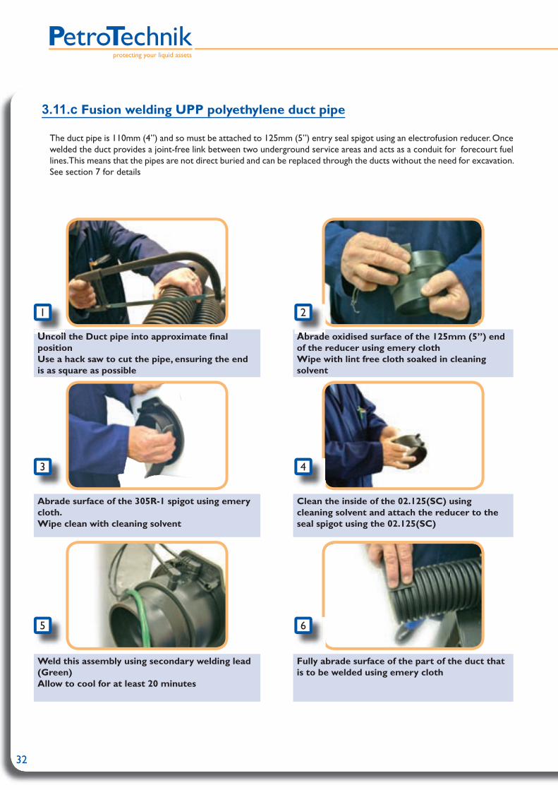
32
protecting your liquid assets
3.11.c Fusion welding UPP polyethylene duct pipe
The duct pipe is 110mm (4”) and so must be attached to 125mm (5”) entry seal spigot using an electrofusion reducer. Once welded the duct provides a joint-free link between two underground service areas and acts as a conduit for forecourt fuel lines. This means that the pipes are not direct buried and can be replaced through the ducts without the need for excavation. See section 7 for details
Uncoil the Duct pipe into approximate fi nal positionUse a hack saw to cut the pipe, ensuring the end is as square as possible
Abrade oxidised surface of the 125mm (5”) end of the reducer using emery clothWipe with lint free cloth soaked in cleaning solvent
Abrade surface of the 305R-1 spigot using emery cloth. Wipe clean with cleaning solvent
Clean the inside of the 02.125(SC) using cleaning solvent and attach the reducer to the seal spigot using the 02.125(SC)
Weld this assembly using secondary welding lead (Green)Allow to cool for at least 20 minutes
Fully abrade surface of the part of the duct that is to be welded using emery cloth
Uncoil the Duct pipe into approximate fi nal Uncoil the Duct pipe into approximate fi nal
1
5
43
Abrade oxidised surface of the 125mm (5”) end Abrade oxidised surface of the 125mm (5”) end
2
6

33
The edges of the corrugations must also be abraded using the emery cloth
Abrade the 110mm (4”) end of the reducer using emery cloth
Wipe the 110mm (4”) end of the reducer with a lint free cloth soaked in cleaning solvent
Wipe the inner surface of the 110mm (4”) coupler with a lint free cloth soaked in cleaning solvent
Wipe the scraped duct pipe with a lint free cloth soaked in cleaning solvent
Attach duct pipe to reducer using the 110mm (4”) coupler. Ensure there are no external stresses acting upon the assembly
Weld with the primary (orange) welding lead Allow to cool for at least 20 minutes
The edges of the corrugations must also be The edges of the corrugations must also be
7
11
109
Abrade the 110mm (4”) end of the reducer Abrade the 110mm (4”) end of the reducer
8
13
12

34
protecting your liquid assets
3.12 Installing UPP Electrofusion FRP Entry Fitting
Drill hole using hole saw:• 4 1/8” (105mm) for FEB-D 075 (Code: HS075)• 5 ½” (140mm) for FEB-D 110 (Code: HS5)
• Abrade external area of sump to be bonded • Use emery cloth
• Abrade inner area of sump to be bonded• Use emery cloth
• Clean inner and outer sump surfaces• Use cleaning solvent
• Clean both fl anges• Use cleaning solvent
• Unscrew movable fl ange and remove from fi tting• Add bonding paste to the grooved side of the
fl ange
1
65
43
2
On A Single Wall Flat/Round Sump
The installation instructions shown here refer to the installation of the FRP entry fi tting (FEB-D 075 or FEB-D 110) on a single wall FRP sump/chamber only.
Basic kit needed• Fusion entry fi tting• 2x FRP caps supplied with fi tting - NOTE internal caps differ from external cap• Gloves (not included)• Cleaning solvent - Trichloroethylene or Acetone (not included)• Composite bonding paste (U-POL brand only- using other paste invalidates warranty)• Fitting wrench - FEB-075-TOOL or FEB-110-TOOL (shown right)
Installation method
Fitting wrench

35
• Add bonding paste to the grooved side of the fi xed fl ange
• Add bonding paste to inner and outer side of sump wall around the entry fi tting hole
7 8
• Fit entry fi tting from outside sump and tighten loose fl ange onto the thread from inside sump
• Tighten fully using supplied wrench tool
• Smooth bonding paste around fl anges on both sides of the sump wall
• Ensure there are no gaps
• Abrade inside of the cover caps using emery • Wipe down with cleaning solvent
• Fill the cover caps with bonding paste
• Fit cover caps over entry fi tting spigots and press fi rmly against sump wall
• Clean off excess resin and smooth with thumb around edge. of cap
9
1413
1211
10

36
protecting your liquid assets
Welding UPP Coaxial Pipe to the Entry Fitting
The UPP secondary containment pipe terminates on the outside of the sump wall where it is welded directly to the entry fi tting spigot using a secondary welding coupler (02.75.SC / 02.110.SC). The primary pipe passes through the fi tting and into the sump. On the inside either an Electrofusion reducer or a termination boot can be used to seal off the interstitial space.
• Allow the paste to cure for 35 minutes (ambient temperature of 71.6ºF/22ºc) before electrofusion
• The unit can now be tightness tested as required.
• Allow the paste to cure for 35 minutes (ambient • Allow the paste to cure for 35 minutes (ambient
15

37
Drill hole using hole saw:• 4 1/8” (105mm) for FEB-D 075 (Code: HS075)• 5 ½” (140mm) for FEB-D 110 (Code: HS5)
• Using the central location hole as a guide, drill through the inside wall of the sump using the same holesaw
• Abrade internal and external area of sump to be bonded
• Use emery cloth
• Clean inner and outer sump surfaces• Use cleaning solvent
• Add bonding paste around the entry hole inside and out.
• Push bonding paste evenly into the cavity between the sump walls
• Unscrew movable fl ange and remove from fi tting • Add bonding paste to the grooved side of the
fl ange
1
65
4
• Abrade internal and external area of sump to be • Abrade internal and external area of sump to be
3
2
3.13 Installing UPP Electrofusion FRP Entry FittingOn A Double Wall Flat/Round Sump
The installation instructions shown here refer to the installation of the FRP entry fi tting (FEB-D 075 or FEB-D 110) on a double wall FRP sump/chamber only.
Basic kit needed• Fusion entry fi tting• 2x FRP caps supplied with fi tting - NOTE internal caps differ from external cap• Gloves (not included)• Cleaning solvent - Trichloroethylene or Acetone (not included)• Composite bonding paste (U-POL brand only- using other paste invalidates warranty)• Fitting wrench - FEB-075-TOOL or FEB-110-TOOL (shown right)
Installation method
Fitting wrench
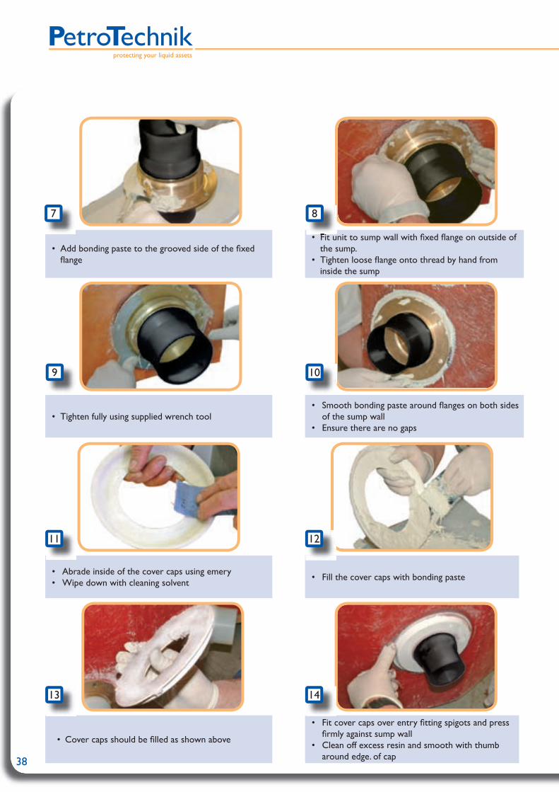
38
protecting your liquid assets
• Add bonding paste to the grooved side of the fi xed fl ange
• Fit unit to sump wall with fi xed fl ange on outside of the sump.
• Tighten loose fl ange onto thread by hand from inside the sump
• Tighten fully using supplied wrench tool• Smooth bonding paste around fl anges on both sides
of the sump wall• Ensure there are no gaps
7
• Fit unit to sump wall with fi xed fl ange on outside of • Fit unit to sump wall with fi xed fl ange on outside of
8
• Abrade inside of the cover caps using emery • Wipe down with cleaning solvent
• Fill the cover caps with bonding paste
• Cover caps should be fi lled as shown above
• Fit cover caps over entry fi tting spigots and press fi rmly against sump wall
• Clean off excess resin and smooth with thumb around edge. of cap
9
1413
1211
10

39
Welding UPP Coaxial Pipe to the Entry Fitting
The UPP secondary containment pipe terminates on the outside of the sump wall where it is welded directly to the entry fi tting spigot using a secondary welding coupler (02.75.SC / 02.110.SC). The primary pipe passes through the fi tting and into the sump. On the inside either an Electrofusion reducer or a termination boot can be used to seal off the interstitial space.
• Allow the paste to cure for 35 minutes (ambient temperature of 71.6ºF/22ºc) before electrofusion
• The unit can now be tightness tested as required.
15

40
protecting your liquid assets
3.14 UPP access cover installation
The following instructions refer specifi cally to the 760x760mm (29 14/16 x 29 14/16”) UPP access cover. The principles of reinforcing the surrounding concrete and water runoff angles are maintained through the entire UPP covers range. The large 950mm (37”) diameter circular cover is slightly different as it has two springs inside the spring box, however the principle of seperating and refi tting the cover from the frame is the same.
Installation instructions• Separate the cover from the frame - see instructions below
• Create a reinforced concrete foundation for the frame, maintaining a clear opening under the frame (800x800mm / 31 4/8”)
• Where specifi ed, connect a 1 inch Ø (26mm) plastic drainage pipe between outlet on frame and oil/water separator or backfi ll material surrounding tank access chamber. Otherwise, ensure bottom of Spring Box (Photo 3) is sealed against water exit
• Pour water into drainage channel in frame to check that drainage operates correctly
• Pour concrete around frame, and check surface water drainage slope is 15º
• Refi t the cover to the frame, once concrete is dry - see instructions below
Seperating the cover from frame - (two operators required)
• Unlock and open the cover to between 30° and 60° using the locking handle PC76/H - Photos 1-2
• Lever up and remove Spring Box Cover - Photo 3
• Continue opening cover to totally open position - circa 120° - Photo 4
• Lift cover from frame - Photo 4
Refi tting the cover to frame - (two operators required)• Place the cover into the frame at circa 120°
• Close the cover to between 30° and 60° - Photo 1-2
• Refi t the Spring Box Cover
Warning - To facilitate drainage of surface water, the frame should be inclined 1: 100 towards the rear. Ensure there will be a 15º slope for surface water drainage from lip of frame to forecourt surface once frame is fi xed in fi nal position
Warning - The cover is heavy (85 kg)
Warning - In this position, the Spring Shaft must be correctly located into the seat in the frame - (Photo 4-5)
1
2
3
4
5

UIM
-V1.00.11.04
41
Maintenance
• Apply grease to spring every year
• There is a rubber gasket on the underside of the cover. To ensure long-term water-tightness the drainage channel in the frame and the gasket should be kept clear of debris
• To renew the gasket:• Scrape off old gasket• Clean off all old adhesive from cover using alcohol, meths or similar• Apply adhesive (Superglue Gel or similar) to channel on underside of cover• Push new gasket into channel• Clean off any excess adhesive around gasket, and close and lock cover
Cast iron cover may be re-painted with any non-slip paint for aesthetic purposes
1:100 incline towards rear of coverto facilitate drainage of surface water.
ReinforcedConcrete.
Drainage Pipe: 26mm
Drainage Pipe Runs into Pea ShingleOr Connects to a Drainage Line,Running To The Oil/Water separator
15° Slope for Surface Water DrainageFromLip of Frame to Forecourt Surface
PC76 Cover
1”

42
protecting your liquid assets
3.15 electrofusion method75/63mm (2” double wall) secondary contained 90° elbow
1. Cut horizontal pipe to required length and trim back 75mm (2” double wall) pipe to dimension shown in drawing
2. Prepare ends of 75mm (2” double wall) pipe and fi ttings as per the instructions in section 3.5
3. Slide reducers and 110mm (4”) welding sockets far enough onto 75mm (2” double wall) pipe at either extremity of the elbow to allow access to 63mm (2”) welding sockets.
4. Prepare ends of 63mm (2”) pipe and fi ttings as per instructions in section 3.5. Fit elbow and 63mm (2”) welding sockets. Weld and allow to cool before proceeding to next step
6. Prepare110mm (4”) welding sockets and sliding reducers as per instructions in section 3.5 (the 110mm (4”) end of the reducers should be treated as secondary pipe). Abrade secondary elbow spigots using emery cloth - slide reducer/coupler onto spigots and weld. Allow to cool before putting any stress on the assembly
7. If required leave secondary un-welded for primary pressure tests to be carried out
8. Prepare secondary contained elbow and welding sockets for welding as per instructions in section 3.5 and weld. Allow to cool to ambient temperature
Position of fi ttings during welding of 63mm (2”) joint
Item Description Code Qty1 75/63mm coaxial (2” double wall) pipe 01.75.63.LS N/A2 63mm (2”) welding socket 02.63 23 110mm (4”) secondary containment 90° elbow 03.110.63(SC) 14 110-75mm (4”-2” double wall) secondary containment sliding reducer 13.110.75(SC) 25 110mm (4”) secondary containment welding socket 02.110(SC) 2

43
3.16 electrofusion method75/63mm (2” double wall) secondary contained tee
1. Cut pipes to required length and trim back 75mm (2” double wall) pipe to dimension shown in drawing below
2. Prepare ends of 75mm (2” double wall) pipes and fi ttings as per the instructions in section 3.5
3. Slide reducers and 110mm (4”) welding sockets far enough onto 75mm (2” double wall) pipe to allow access to 63mm (2”) welding sockets
4. Prepare ends of 63mm (2”) pipe and fi ttings as per instructions in section 3.5
5. Fit tee and 63mm (2”) welding sockets. Weld and allow to cool before proceeding to next step
6. If required leave secondary containment un-welded to allow primary pressure tests to be carried out
6. Prepare 110mm (4”) welding sockets and sliding reducers as per instructions in section 3.5 (the 110mm (4”) end of the reducers should be treated as secondary pipe). Abrade secondary tee spigots using emery cloth - slide reducer/coupler onto spigots and weld. Allow to cool before putting any stress on the assembly
7. Allow to cool before stressing the pipe
Position of fi ttings during welding of 63mm (2”) joint
Item Description Code Qty1 75/63mm coaxial (2” double wall) Pipe 01.75.63.LS N/A2 110-75mm (4”-2” double wall) secondary containment sliding reducer 13.110.75(SC) 33 63mm (2”) welding socket 02.63 34 110mm (4”) secondary containment welding socket 02.110(SC) 35 110/63mm (4”/2”) secondary containment tee 08.110.63(SC) 1
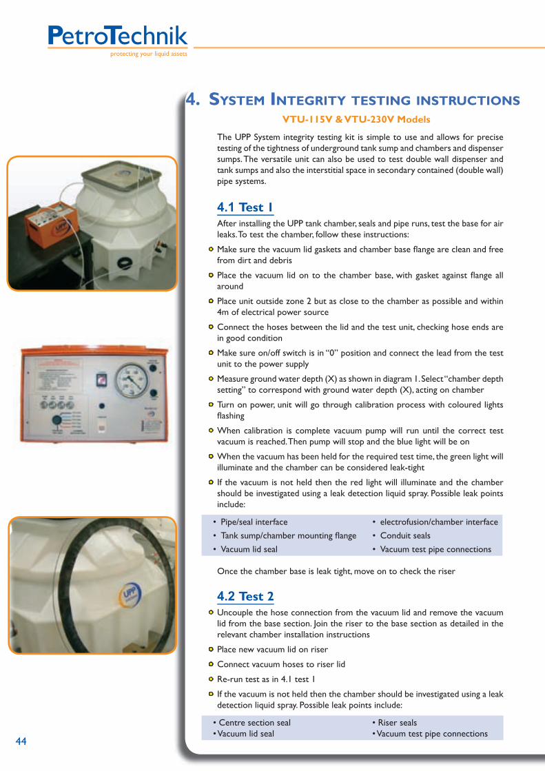
44
protecting your liquid assets
4. SYSTEM INTEGRITY TESTING INSTRUCTIONSVTU-115V & VTU-230V Models
The UPP System integrity testing kit is simple to use and allows for precise testing of the tightness of underground tank sump and chambers and dispenser sumps. The versatile unit can also be used to test double wall dispenser and tank sumps and also the interstitial space in secondary contained (double wall) pipe systems.
4.1 Test 1 After installing the UPP tank chamber, seals and pipe runs, test the base for air
leaks. To test the chamber, follow these instructions:
• Make sure the vacuum lid gaskets and chamber base fl ange are clean and free from dirt and debris
• Place the vacuum lid on to the chamber base, with gasket against fl ange all around
• Place unit outside zone 2 but as close to the chamber as possible and within 4m of electrical power source
• Connect the hoses between the lid and the test unit, checking hose ends are in good condition
• Make sure on/off switch is in “0” position and connect the lead from the test unit to the power supply
• Measure ground water depth (X) as shown in diagram 1. Select “chamber depth setting” to correspond with ground water depth (X), acting on chamber
• Turn on power, unit will go through calibration process with coloured lights fl ashing
• When calibration is complete vacuum pump will run until the correct test vacuum is reached. Then pump will stop and the blue light will be on
• When the vacuum has been held for the required test time, the green light will illuminate and the chamber can be considered leak-tight
• If the vacuum is not held then the red light will illuminate and the chamber should be investigated using a leak detection liquid spray. Possible leak points include:
• Pipe/seal interface • electrofusion/chamber interface• Tank sump/chamber mounting fl ange • Conduit seals• Vacuum lid seal • Vacuum test pipe connections
Once the chamber base is leak tight, move on to check the riser
4.2 Test 2• Uncouple the hose connection from the vacuum lid and remove the vacuum
lid from the base section. Join the riser to the base section as detailed in the relevant chamber installation instructions
• Place new vacuum lid on riser
• Connect vacuum hoses to riser lid
• Re-run test as in 4.1 test 1
• If the vacuum is not held then the chamber should be investigated using a leak detection liquid spray. Possible leak points include:
• Centre section seal • Vacuum lid seal
• Riser seals• Vacuum test pipe connections

UIM
-V1.00.11.04
45
Fault Solution
Vacuum level not reached or keeps on falling
Check and listen for leaks in all the areas outlined in the two tests. Rectify faults if found
Vacuum still falling. All areas on chamber are leak tight
Check manway tank fl ange and fi ttings for leak path. Contact tank manufacturer if leak is found for alternative sealing solutions.Fault on test unit, send to PetroTechnik for repair
Vacuum equipment running but no vacuum being produced
Check connection to vacuum lid and pump. To check pump, block one end of pipe and monitor the movement of the vacuum gauge. Send to PetroTechnik for repair if a vacuum is not generated
Pump not running Check power to unit and electrical fuse
4.3 Fault diagnosis
Vac test levels and corresponding water pressures Vacuum Test Level (x) Ground Water Pressure Test Time
mm ft mbar Psi in Hg mins
300 1 30 0.43 0.89 10600 2 60 0.87 1.77 10900 3 90 1.30 2.66 15
1200 4 120 1.74 3.54 201800 6 180 2.60 5.32 20
UPP Product Max Vaccum Level DC4830.SBDS2111DS4111DS3017DS4417DS3617

46
protecting your liquid assets
5. TIGHTNESS TESTING Every completed UPP systems installation must be tightness tested by a
competent person to verfi y the integrity of the line(s) prior to backfi lling. Testing can be done by pressure or vacuum. Guidelines for these tests are set
out below but these procedures may need to be validated and amended to meet the requirements of the local offi cials and engineers and to comply with local health and safety regulations
Testing Guidelines
• It is recommended for accuracy of observation that the test gauge scaling is such that the target test pressure is approximately 50% of the gauges maximum range.
e.g. test pressure = 4 bar (58psig) – gauge range is 0 to 8 bar (0 to 116psig).
• All gauges should bear a unique mark (serial number) and be tested at least annually to ensure that they comply with the accuracy specifi ed in local standards. A current test certifi cate /certifi cate of compliance should be held for each gauge.
• The fi ttings which are used to introduce air or an inert gas into the pipes must incorporate a shut off valve between the pipe and the pressure gauge and a shut off valve between the pressure supply and the gauge.
• To ensure that excess pressure cannot be applied to a pipe under test, a relief valve must also be incorporated in the system. The relief valve should be set so that at possible full fl ow from the pressure supply the pressure in the pipe cannot exceed 0.5 bar (7.25 psig) above test pressure.
e.g. test pressure of 4 bar (58 psig) – relief valve set to 4.5 bar
• When air or inert gas is to be applied from high pressure cylinders, a suitable control valve must be used to control the fl ow from the cylinder. The outlet pressure from the cylinder must be set to ensure that it does not exceed the required / approved test pressure whilst pressure is being applied to the pipe.
• When conducting the pressure/vacuum test on the primary pipework any secondary containment must be open to atmosphere. The reverse is true when conducting the pressure/vacuum test on any secondary containment the primary must be open to atmosphere.
• The line under test should be slowly pressurized (or de-pressurized for vacuum) to minimize any risks.
• Caution: Nitrogen from a pressure cylinder shall be used in lieu of air for
testing if a fuel has been used to ballast an underground storage tank.
• Check that all pipework is disconnected (isolated) from the underground storage tank prior to commencing pipe pressure testing.

UIM
-V1.00.11.04
47
5.1 Tightness testing procedure
Test Pressure/Vacuum level
Allowable pressure variation over 30
minutesPressure TestingNon-pressure lines(suction, fi ll, vent, VR)
0.7 bar ± 0.04 bar10 Psi ± 0.5 Psi
-0 to 0.04 bar-0 to 0.5 Psi
Pressure lines4.2 bar ± 0.04 bar
60 Psi ± 0.5 Psi-0 to 0.04 bar-0 to 0.5 Psi
Secondary containment terminated with fl exible boot
0.5 bar ± 0.04 bar7 Psi ± 0.5 Psi
-0 to 0.04 bar-0 to 0.5 Psi
Secondary containment terminated with electrofusion boot
4 bar ± 0.04 bar58 Psi ± 0.5 Psi
-0 to 0.04 bar-0 to 0.5 Psi
Duct line 0.5 bar ± 0.04 bar7 Psi ± 0.5 Psi
-0 to 0.04 bar-0 to 0.5 Psi
Vacuum Testing
Primary product, fi ll, vent and VR lines
-0.6 bar ± 0.04 bar- 8.7 Psi ± 0.5 Psi
-17.71 in.HG ± 1.02
-0 to 0.04 bar-0 to 0.5 Psi
-0 to 1.02 in.HG
Secondary Containment (in.HG = inches of mercury)
-0.3 bar ± 0.04 bar-4.4 Psi ± 0.5 Psi
-8.96 in.HG ± 1.02
-0 to 0.04 bar-0 to 0.5 Psi
-0 to 1.02 in.HG
• There must be no visual or any other indication of leakage of air/gas or water during the test period
• If during the 30 minute test period the pressure variation exceeds the allowed value (see table above) it must be assumed there is a leak in the system
• It is preferable to wipe each joint with a soapy water mixture to check for signs of leakage (particularly in the area where the primary pipe exits from the secondary containment, if applicable)
• Use Nitrogen from a pressure cylinder in lieu of air for testing if a fuel has been used to ballast an underground storage tank
• Check that all pipework is disconnected (isolated) from the underground storage tank prior to commencing pipe pressure testing
Note: Due regard must be taken of pressure variations due to temperature effects
A vacuum/pressure should be applied to the pipework being tested for at least 30 minutes - the table below shows the respective pressures/vacuums that should be applied to the various types of UPP pipe systems

48
protecting your liquid assets
5.12 Tightness testing on operational sites
• Special precautions must be taken when testing on operational pipework or pipework connected to any tank or pipework that has previously contained petroleum, to avoid the possibility of explosion hazards from vapour or air mixtures
• An inert gas, normally nitrogen, must be used for pressurisation instead of air• Any water used must be disposed of either through the oil/water separator or
by a specialist contractor as contaminated waste• In all other aspects the pressure testing requirements are as detailed above
5.2 Testing at maximum operating pressure
Equipment needed• Pump rated for more than 10 bar (145 psig)• Hydrofor• Two pressure gauges, rated for 12 bar (174 psig), min. reading 0.1 bar (2 psig)• Check valve• Ball valve• Pressure relief valve rated for 20 bar (290 psig), set at 11bar (159 psig)
Procedure• Leak test with air (2 bar / 29 psig) and soapy water on all welds and
terminations• Protect the pipe from direct sunlight, preferably with sand• Fill the pipe with liquid, preferably water (or oil)• Apply working pressure to the pipe after the temperature has equalized • Maintain the pressure on the pipe until the pressure stabilizes i.e. pressure
drop is less than 0.1 bar (2 psig)• Close the ball valve; note time and pressure• Test pressure should continue to be applied for four hours• If the pressure drop is less than 0.1 (2 psig) bar, the pipe may be considered as
being tight
5.3 UPP Pipe ratings
IP Rating UL Rating ULC RatingUPP primary pipe (single wall)
Unlined: 50/63/90mm (1.5”/2”/3”)
10 bar (145 Psi)
Lined: 32/50/63/90/110/160mm(1”/1.5”/2”/3”/4”/6”)
10 bar (145 Psi)
6.2 bar (90Psi)
6.2 bar(90Psi)
Lined: 110mm fi ll pipe(4” fi ll pipe)
2 bar(29 Psi)
UPP Secondary containment (double wall)
Terminated by fusion fi tting4 bar
(58 Psi)4 bar
(58 Psi)1.03 bar(15 Psi)
Terminated by fl exible boot0.5 bar
(1.03 Psi)1.03 bar(15 Psi)
1.03 bar(15 Psi)
Duct Pipe 0.5 bar(1.03 Psi)

49
5.4 Primary (single wall) - tightness test reportTEST REPORT
Intermediate / Final Tightness PRESSURE TEST on UPP pipework system Single Wall - Primary Containment
Installation Details
Site name & address ………………………………………………………………………………………..
Site Owner / operator ………………………………………………………………………………………..
Pipe Type & Usage Suction Syphon Pressure (Atmospheric / Pumped) VR 1b UPP Extra (lined) VR 2 UPP (unlined)
UPP Ø mm 32mm 50 mm 63 mm 90 mm 110 mm 110 mm Fill 160 mm
Wall thickness 3.2 mm 4.6 mm 5.8 mm 8.2 mm 10.0 mm 6.5 mm 11.8 mm
Pressure Rating PN10 PN10 PN10 PN10 PN10 PN2 PN10
Meter marking or applied ID ……………..………………………………………………………………………
Conformance Control Pipe marking Pipe routing / crossings Fusion welds No. of welds ………. Minimum Fall …. %
Tightness Test Test Pressure …... bar / psig Test Duration …... minutes / hours Start ….. Finish ….. Test Medium Air Inert Gas (Nitrogen) Water Pressure drop ….. mbar over test period Ambient temperature …… ºC
Certification The above described pipe run has been installed in accordance with the Installation Instructions for UPP by personnel employed / supervised by:
…………………………………………………………………………………………………………...……….The information given above is true and correct.
Signed by: ……………………….. Date: dd / mm / 200…
This copy for: Control Authority Site Owner Contractor ……..

50
protecting your liquid assets
5.5 Secondary (double wall) - tightness test reportTEST REPORT
Intermediate / Final Tightness PRESSURE TEST on UPP pipework system Double Wall - Secondary Containment
Installation Details
Site name & address ………………………………………………………………………………………..
Site Owner / operator ………………………………………………………………………………………..
Pipe Type & Usage Suction Syphon Pressure (Atmospheric / Pumped) UPP Extra (lined) VR 1b UPP Extra Co Axial (lined) VR 2 UPP Secondary
UPP Ø mm 40 mm 63 mm 75 mm 110 mm 160 mm 200 mm
Wall thickness 3.0 mm 3.0 mm 3.0 mm 4.2 mm 6.2 mm 7.7 mm
Pressure Rating PN4 PN4 PN4 PN4 PN4 PN4
Meter marking or applied ID ………………………………………………………………………….…………
Conformance Control Pipe marking Pipe routing / crossings Fusion welds No. of welds ………. Minimum Fall …. %
Tightness Test Test Pressure …... bar / psig Test Duration …... minutes / hours Start ….. Finish ….. Test Medium Air Inert Gas (Nitrogen) Water Pressure drop ….. mbar over test period Ambient temperature …… ºC
Certification The above described pipe run has been installed in accordance with the Installation Instructions for UPP by personnel employed / supervised by:
…………………………………………………………………………………………………..………………..The information given above is true and correct.
Signed by: ……………………….. Date: dd / mm / 200…
This copy for: Control Authority Site Owner Contractor …….. TEST REPORT
Intermediate / Final Tightness PRESSURE TEST on UPP pipework system Single Wall - Duct Containment
Installation Details

51
5.6 Duct Containment Pipe - tightness test reportIntermediate / Final Tightness PRESSURE TEST on UPP pipework system
Single Wall - Duct Containment
Installation Details
Site name & address ………………………………………………………………………………………..
Site Owner / operator ………………………………………………………………………………………..
Duct Pipe Used In Conjunction With Suction UPP Extra (lined) Pressure (Atmospheric / Pumped) UPP Extra Co Axial Extra (lined) VR 2 UPP (unlined)
UPP Ø mm 110 mm 125 mm
Wall thickness Corrugate 8.0 mm
Material 0.5 mm Corrugate 8.0 mm Material 0.5 mm
Pressure Rating N/a N/a
Meter marking or applied ID …………………….………………………………………………………………
Conformance Control Pipe marking Pipe routing / crossings Fusion welds No. of welds ………. Minimum Fall …. %
Tightness Test Test Pressure …... bar / psig Test Duration …... minutes / hours Start ….. Finish ….. Test Medium Air Inert Gas (Nitrogen) Water Pressure drop ….. mbar over test period Ambient temperature …… ºC
Certification The above described pipe run has been installed in accordance with the Installation Instructions for UPP by personnel employed / supervised by:
………………………………………………………………………………………...………………………….The information given above is true and correct.
Signed by: ……………………….. Date: dd / mm / 200…
This copy for: Control Authority Site Owner Contractor ……..

52
protecting your liquid assets
6. MODIFICATION AND REPAIR OF UPP SITES
This section is designed as an advisory guideline on the how to modify or
repair an existing UPP site.
The site should be prepared in advance to either close or restrict access to the work area, and all equipment should be checked to ensure that it is in operational condition.
During any modifi cation or repair work to UPP pipework, the safety of on-site personnel is paramount and all national, regional and local health and safety legislation should always be adhered to.
The following ‘checklist’ gives a step-by-step guide to ensuring that the modifi cation is carried out in the safest possible manner. However relevant local health and safety regulations should take precedence over the advice given here.
Method
1 Switch off - shut down submersible pump and dispensers in works area
2 Tag out - remove fuses or isolating breaker to pumps and dispensers
3 Prepare to empty product into an approved sealable containment vessel
4 Operate the hose of the product dispenser closest to the underground storage tank to release pipeline pressure and empty product into container. Continue this process until no further liquid petroleum is discharged
5 Check the sump where the repair is to be made with an O2 meter and record the presence of suffi cient oxygen (~21% O2) before any personnel enter the sump. Air exchange if necessary
6 Isolate the submersible pump by closing the isolation valve (ball valve)
7 All secondary containment lines will need to have their test boots removed
8 Break (disconnect) the product supply line at the tank sump, allowing for any residual petroleum liquid contained within the product line to fl ow out into the approved sealable containment vessel
9 Open the shear valve access ports of the affected lines to allow the petroleum liquid to drain down to the tank sump
10 Shut (close) all the shear valve access ports once no further fuel fl ows out of the product line
12 The sump air supply should be exchanged until the O2 meter records the presence of suffi cient oxygen (~21% O2) before any personnel re-enter the sump
13 Remove the petroleum liquid containment vessel from the tank sump
UIM
-V1.00.11.04
53
14 Undertake and complete the repair to the UPP pipework and fi ttings up to the point of welding in accordance with UPP installation instructions
15 The repair assembly of UPP pipework and fi tting(s) is to be clamped or supported and not subject to strain during welding and cooling periods
16 The pipe should be open to the sump to allow the Nitrogen purge to inert the sump as well as the line. The welding lead should be attached to the welding coupler / fi tting in preparation for electrofusion. The welding lead should not be connected to the welding machine at this stage
17 The atmosphere of the sump is to be continually monitored with the O2 meter for the presence of suffi cient oxygen (~21% O2) during repair whilst personnel are within the sump
18 Connect the nitrogen supply to a shear valve access port and fl ood the product line and sump, the O2 meter should record the presence of no oxygen in the sump
19 Once no oxygen is recorded on the O2 meter, the welding machine and power supply can be located above ground at the furthest point at which the welding lead will reach the welding machine without any tension on the lead
20 Shut off (stop) the nitrogen supply just prior to the welding machine being switched on and the welding cycle activated
21 On completion of welding cycle, the welder should be isolated from the power supply and the nitrogen purging should recommence and continue for a period no less than 15 minutes
22 During this time period no personnel should enter the tank sump to remove the welding leads
23 The sump air supply should be exchanged until the O2 meter, records the presence of suffi cient oxygen (~21% O2) before any personnel enter the sump
24 Before undertaking any additional work on any of the other sumps, the atmosphere should be checked with the O2 meter and records the presence of suffi cient oxygen (~21% O2), initiate air exchange if in any doubt
25 All the effected shear valves should have the access port re-sealed ready for the product line to be pressure tested
26 The product line should be pressure tested to the UPP guidelines (60psi or 4.2bar) for 1 hour. The new welded joint should be wiped with soapy water to make it easier to check for signs of leakage
27 Perform any regulatory testing requirements and sign offs as required
28 On completion of a successful pressure test, the submersible pump can be re-connected and the dispensers re-commissioned
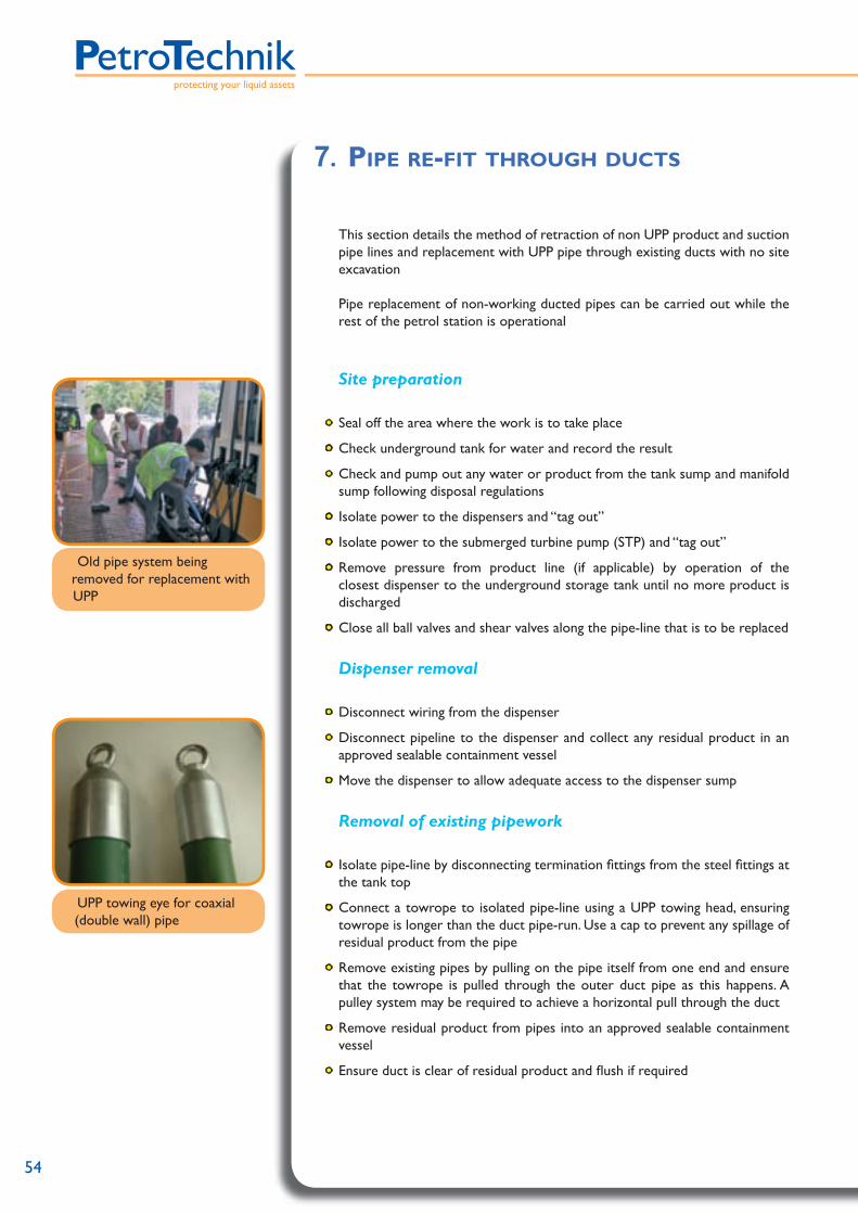
54
protecting your liquid assets
This section details the method of retraction of non UPP product and suction
pipe lines and replacement with UPP pipe through existing ducts with no site excavation
Pipe replacement of non-working ducted pipes can be carried out while the rest of the petrol station is operational
Site preparation
• Seal off the area where the work is to take place
• Check underground tank for water and record the result
• Check and pump out any water or product from the tank sump and manifold sump following disposal regulations
• Isolate power to the dispensers and “tag out”
• Isolate power to the submerged turbine pump (STP) and “tag out”
• Remove pressure from product line (if applicable) by operation of the closest dispenser to the underground storage tank until no more product is discharged
• Close all ball valves and shear valves along the pipe-line that is to be replaced
Dispenser removal
• Disconnect wiring from the dispenser
• Disconnect pipeline to the dispenser and collect any residual product in an approved sealable containment vessel
• Move the dispenser to allow adequate access to the dispenser sump
Removal of existing pipework
• Isolate pipe-line by disconnecting termination fi ttings from the steel fi ttings at the tank top
• Connect a towrope to isolated pipe-line using a UPP towing head, ensuring towrope is longer than the duct pipe-run. Use a cap to prevent any spillage of residual product from the pipe
• Remove existing pipes by pulling on the pipe itself from one end and ensure that the towrope is pulled through the outer duct pipe as this happens. A pulley system may be required to achieve a horizontal pull through the duct
• Remove residual product from pipes into an approved sealable containment vessel
• Ensure duct is clear of residual product and fl ush if required
7. PIPE RE-FIT THROUGH DUCTS
UPP towing eye for coaxial (double wall) pipe
Old pipe system being removed for replacement with UPP

UIM
-V1.00.11.04
55
Installing UPP pipe
• Mark and cut UPP pipe 1m (3ft) longer than necessary. This is because the UPP towing eye damages the area of the pipe into which it is inserted and this must be removed after towing
• Fit UPP towing head into pipe and secure the towrope
• Ensure the non-towing ends are capped to prevent contamination from existing outer pipe into new UPP pipe
• Install UPP through the duct by pulling on the towrope and pushing on the opposite pipe end if necessary. A pulley system may be required to achieve a horizontal pull through the duct
• Remove the towing eye and cut back the pipe where it was attached as this will have a damaged liner
• Install appropriate UPP fi ttings at either end of new pipeline and re-attach pipeline to steel tanktop fi ttings
• Install fl exible connectors and ball valves
• Tightness test the pipelines following our guidelines in ‘Section 5 - Tightness Testing’
Re-fi t and re-commission dispenser
• Replace dispenser and secure with bolts
• Re-connect fl exible connector to dispenser via the shear-valve and connect the shear-valve to the sump stabiliser bar framework
• Re-connect electrics
• Open Ball valves and re-instate power to STP and dispenser
Flush new lines
• The line needs to be bled of air to ensure the STP mechanical leak detector returns to its normal operating position
• Conduct a visual inspection of piping connections paying particular attention to threaded joints on ball valves, fl exible connectors and shear-off valves checking for seepage
• Correct fl ushing means dispensing 200 litres (53gallons) of product from furthest dispenser on product line and 50 litres from all other dispenser nozzles
Ask the station manager to verify the quality of the product being dispensed
Place the dispenser back into operation
Site operational whilst refi tting work is still ongoing
UPP pipe being guided into duct

56
protecting your liquid assets
8. WATER HAMMER EFFECT
A quick change of the fl ow inside a piping system can cause a sudden pressure increase over and above the nominal working pressure. This “water hammer” effect can occur every time a valve is opened/closed or a pump is started/shut off. The formula for pressure variation (∆P) is given by
∆P = p . c . ∆v
Where p is the density of water, ∆v is the fl uid velocity change and c is the velocity of a shock wave in the pipe.
c depends on the elasticity of the fl uid in the pipe wall and, for a freely supported pipe is given by:
Where Ew is the water elasticity modulus, Ep the pipe elastictiy modulus, P the
water density, Dm the mean pipe diameter and the pipe wall thickness.
The following diagram shows the water hammer effect for various types of piping, the fl uid considered in this test is water.
Thanks to its fl exibility UPP pipework is the pipe system with the lowest peak pressure.
c =
Ep
P
EpDm
Ew t+
UPP
Fibreglass
Steel
60,00
0,00
10,00
20,00
30,00
40,00
50,00
50.5 1 1.5 2 2.5 3 3.5 4 4.50Initial Velocity
Peak
Pre
ssur
e (b
ar)
Water hammer effect for various piping systems

UIM
-V1.00.11.04
57
9. FUEL FLOW
50mm (1 1/2”)
63mm (2”)
6
0
1
2
3
4
5
10010 20 30 40 50 60 70 80 900
Litres per minute
Hea
d Lo
ss (
m/1
00m
)
UPP Extra lined pipe - Flow loss Rates
90mm (3”)
110mm (4”)
0.30
0
0.05
0.1
0.15
0.20
0.25
10010 20 30 40 50 60 70 80 900
Litres per minute
Hea
d Lo
ss (
m/1
00m
)
UPP Extra lined pipe and fi ll pipe - Flow loss rates
110mm (4”) Fill

58
protecting your liquid assets
UPP ready reckoner for fl ows to 3,000 litres per minute (790 US gal/min)PetroTechnik Ltd www.upp.co.uk UPP Ready Reckoner for Flows to 3,000 litres per minute
Velocity of liquid fuel and fuel vapour flow is given in m/sec and ft/min
Nominal Pipe Size inches 1” 1 ½” 2” 3” 4” 4” 6” 8” DN25 DN40 DN50 DN80 DN100 DN100 DN150 DN200
UPP Pipe code 01.32.x 01.50.x 01.63.x 01.90.x 01.110.x 01-110-FILL
01.160.x 01.200.x
Pressure Rating PN10 PN10 PN10 PN10 PN10 PN2 PN10 PN10 Polyethylene Grade PE80 PE80 PE80 PE80 PE80 PE80 PE100 PE100 Wall Thickness min. mm 3.0 4.6 5.8 8.2 10 6.6 11.8 14.7Internal Diameter nom. mm 26.0 40.8 51.4 73.6 90 96.8 136.4 170.6Cross Sectional Area mm² 531 1,308 2,075 4,255 6,362 7,359 14,612 22859
in² 0.82 2.03 3.22 6.60 9.86 11.41 22.65 35.44Availability Stock Stock Stock Stock Stock Stock Stock Request
FLOW < - - - - - - - - - - - - - - - - - - - Velocity - - - - - - - - - - - - - - - - - - - - - - - - - - > 45 l/m = 1 Nozzle
V = m/s
1.41 0.57 0.36 0.18
12 US Gal/min V = ft/min
282 114 72 36
90 l/m = 2 Nozzles, or 1 Regular Diesel
V = m/s
2.83 1.15 0.72 0.35
24 US Gal/min V = ft/min
566 230 144 70
135 l/m = 3 Nozzles or 1 Hi-Flow Diesel
V = m/s
4.48 1.72 1.08 0.53 0.35 0.30 0.16
36 US Gal/min V = ft/min
836 344 216 106 70 60 32
200 l/m = 5 Nozzles or 2 Regular Diesel
V = m/s
6.28 2.55 1.60 0.78 0.52 0.45 0.23 0.15
50 US Gal/min V = ft/min
1256 510 320 156 104 90 46 30
400 l/m V = m/s
5.10 3.22 1.57 1.05 0.90 0.46 0.29
105 US Gal/min V = ft/min
1020 644 314 210 180 92 56
600 l/m = Gravity Fill
V = m/s
7.66 4.82 2.35 1.57 1.36 0.69 0.44
160 US Gal/min V = ft/min
1532 964 470 314 272 138 88
1 M³/m = Pumped Fill
V = m/s
8.04 3.92 2.62 2.27 1.14 0.73
260 US Gal/min V = ft/min
1608 784 524 454 228 146
2 M³/m V = m/s
7.84 5.24 4.53 2.28 1.46
530 US Gal/min V = ft/min
1568 1048 906 456 292
3 M³/m V = m/s
3.42 2.19
790 US Gal/min V = ft/min
684 438
NOTE Liquid fuel flows upto 1 m/s ~ 200 ft/min are considered best for Suction systems Liquid fuel flows upto 3 m/s ~ 600 ft/min are acceptable for Pressure (pumped) systems Airflows upto 10 m/s ~ 2,000 ft/min may be acceptable in Pressure Equalization (tank venting) pipes Liquid fuel flows over 3.5 m/s ~ 700 ft/min may be prohibited in certain countries and should be selected only by
experienced engineers. Please consult PetroTechnik Ltd
Velocity of liquid fuel and vapour fl ow is given in m/sec and ft/min
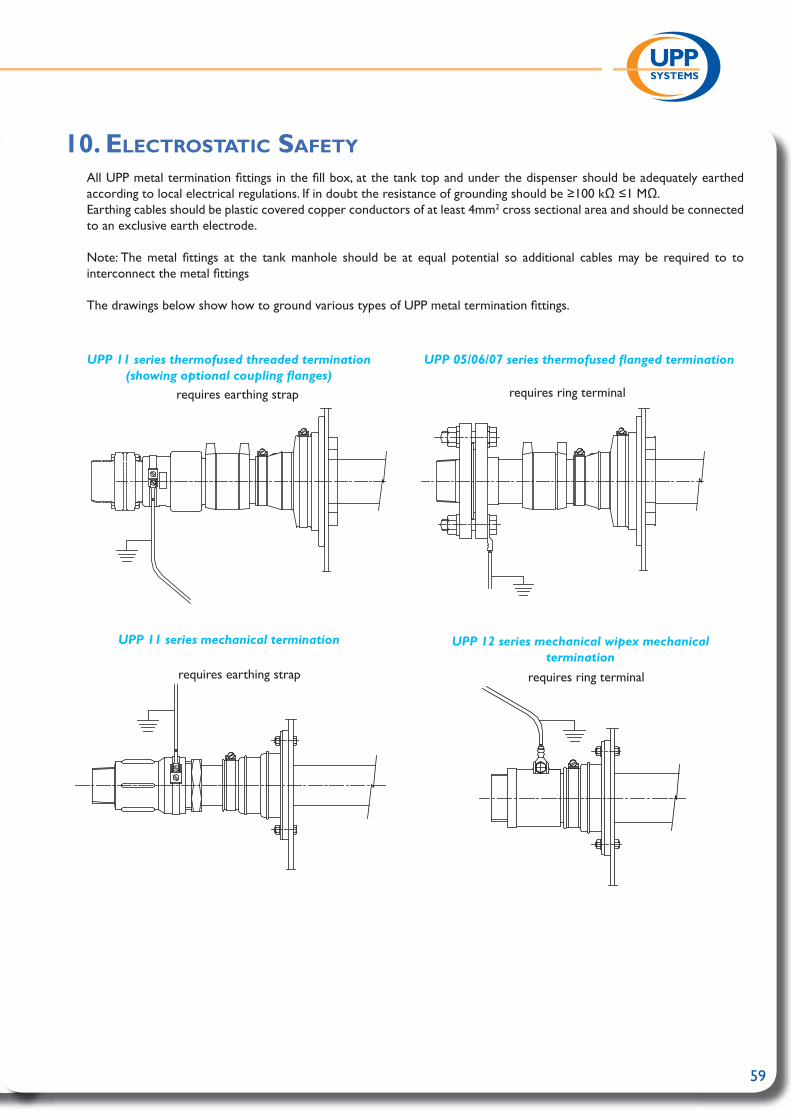
59
10. ELECTROSTATIC SAFETY
All UPP metal termination fi ttings in the fi ll box, at the tank top and under the dispenser should be adequately earthed according to local electrical regulations. If in doubt the resistance of grounding should be ≥100 kΩ ≤1 MΩ.
Earthing cables should be plastic covered copper conductors of at least 4mm2 cross sectional area and should be connected to an exclusive earth electrode.
Note: The metal fi ttings at the tank manhole should be at equal potential so additional cables may be required to to interconnect the metal fi ttings
The drawings below show how to ground various types of UPP metal termination fi ttings.
UPP 11 series thermofused threaded termination (showing optional coupling fl anges)
UPP 05/06/07 series thermofused fl anged termination
UPP 11 series mechanical termination UPP 12 series mechanical wipex mechanical termination
requires earthing strap
requires ring terminalrequires earthing strap
requires ring terminal

60
protecting your liquid assets
It should be noted that PetroTechniks UPP System complies with BS 5958 and with the spirit of the CENELEC R044-001 document (buried plastic pipes having been rigorously tested for electrostatic safety by independent organisations).
This question and answer section has been compiled to answer the most commonly found questions on the issues of electrostatic generation in fuel-carrying plastic pipeline systems.
Q1 What is static electricity and why is it considered a hazard?A Static electricity is an electrical charge which is produced when two surfaces are
brought together and then separated (for example fuel and pipe). It is possible for an electrical charge to accumulate on insulating materials, such as plastic, and on ungrounded conductors, such as metal parts or even personnel.
Static electricity becomes an ignition hazard only when an electrostatic discharge (ESD) occurs, such as by the generation of a spark. Static electricity is a low power (but potentially a high voltage) phenomenon and ESDs only pose a threat to sensitive materials such as fl ammable hydrocarbons and fi ne combustible dusts.
Q2 Is any electrostatic charge generated during fuel fl ow through a pipe?A Yes. Some modern fuels have a low electrical conductivity (measured in
picoSiemens/m) and will generate an electrostatic charge during handling operations such as pouring, splashing, agitation and transport through pipes and fi lters.
Q3 How does the level of electrostatic charge generation compare between metal and plastic pipes?
A Generally, the level of charge generation in the fuel is higher with metal pipes than with plastic pipes. Static electricity occurs in the fuel due to a charge separation process at the pipe wall. If the pipe wall is a grounded conductor it can supply more electrical energy to the charge separation process.
Q4 You need an electrostatic discharge (ESD) to ignite fuel vapour. Where are these likely to occur?
A The most likely electrostatic ignition source is a spark from an ungrounded piece of metalwork that has in some way acquired suffi cient electrical charge.
Q5 Can you get electrostatic sparks from the surface of plastic pipes?A No. Spark discharges only occur from conductive objects and plastic pipes are
insulating in nature. Plastic surfaces can give rise to the less incendive brush discharges if they have acquired a high level of surface charge density. Wolfson Electrostatics has not observed this due to fuel fl ow in any plastic pipe system so far tested.
Q6 Are plastic materials commonly in use for fuel handling?A The use of plastics is now widespread in a number of applications. GRP, Nylon
and polyethylene pipe have been installed in tens of thousands of forecourts in over 120 countries throughout the world and virtually all modern motor vehicles now incorporate a plastic fuel tank and fi ller pipe. Some fuel storage vessels are also constructed from plastic, such as the common 5-litre emergency fuel tank.

UIM
-V1.00.11.04
61
Q7 Have there been any reports of electrostatic ignitions attributed specifi cally to the use of plastic underground pipework?
A There have been no reported incidents relating to UPP pipe. Five million metres of UPP pipe has been installed in 15,000 sites over 120 countries.
Q8 Which Standards apply to this subject?A The Cenelec CLC/TR 50404 and 7.4 of EN 13463-1:2001 reports are
considered the best standards for this subject
Q9 Is there a safety audit that can be applied to such pipework systems?A A test method has been developed which has been accepted and approved for
example by the London Fire Brigade and Civil Defence Authority in the UK and other fi re authorities worldwide
Q10 How well does the UPP system fare in this audit?A Results from the audit show that the UPP system performs safely with respect to
electrostatic hazard, provided that the system is installed correctly according to the manufacturers’ instructions and any additional industry specifi c regulations.
Q11 Have plastic pipes been tested under worst case conditions for electrostatic hazard?
A Certainly. Tests by Wolfson ElectroStatics have used low conductivity fuel (down to ~ 20pS/m) at high fl ow velocities up to 12m/s [8]. UPP pipework passed the wolfson audit to the current European standards (and therefore is also certifi ed by the Institute of Petroleum)
Certificate of Electrostatic Safety Presented to
PetroTechnik Ltd for
UPP Piping System
This is to certify that the UPP piping system (including UPP Extra primary pipe and UPP SC secondary contained pipe and respective HD-PE and metal terminations) audited by Wolfson Electrostatics at the University of Southampton has been rigorously tested and has been found to be safe in respect of electrostatic ignition hazards.
The system also meets Institute of Petroleum Performance Specification for Underground Pipework Systems at Petrol filling Stations 2nd Edition (Feb 2001) Section 6.9 and IEC 60243 Part 2 (2001).
The UPP products encompassed in this audit and detailed in Wolfson Electrostatics Technical Reports 187/99 *, 363/96 **, 369/96 *** and 378/97 **** are suitable for use in fuel handling applications involving gasoline (petrol) liquids and vapours and Diesel.
*- earthed metal couplings ** - velocities upto 12 m/s *** - Jet A1 and Fuel C **** - fuel conductivity from 5 pS.m-1
_____________________________________ For and on behalf of Wolfson Electrostatics 4th June 2003
Department of Electronics & Computer Science University of Southampton Southampton SO17 1BJ England
Telephone: +44 (0)23 8055 2266 Fax: +44 (0)23 8059 3015 E-mail: [email protected] www.soton.ac.uk/~wolfson
2001RAE
Wolfson Electrostaticsw

62
protecting your liquid assets
11. FREQUENTLY ASKED QUESTIONS
Q1 Is UPP pipe fl exible or rigid?A UPP pipe combines the best of both worlds, it is fl exible enough to coil
and bend for ease of installation but rigid enough to be used for vapour recovery (VR) lines
Q2 Within which ambient temperature range can electrofusion welding can
be carried out?A From -10°C to 45°C (14°F to 113°F)
Q3 What are the recommended backfi ll materials for bedding and burial of UPP pipe and fi ttings?
A See section 2.2 of this manual for bedding and backfi ll instructions
Q4 What is the minimum burial depth recommended for UPP pipe and fi ttings?
A• 300mm (12”)
Q5 Can point loading damage affect pipes that cross each other below ground?
A Yes, crossing pipes should be protected by a minimum of 5 cm (2”) of compacted backfi ll or 2.5 cm (1”) of protective Styrofoam
Q6 Is it important to align pipe and fi ttings, both during welding and cooling process?
A Yes, it is very important to align pipe and fi ttings, both during welding and cooling process and ensure there are no external stresses or loading acting on weld assemblies.
Q7 In the event of a power shortage, can electrofusion welding be restarted?
A Yes, but the assembly must have completely cooled down to ambient temperature before electrofusion is restarted
Q8 What are the differences between the UPP pipe system versus the braided fl exible piping systems?
A UPP is different from braided fl exible piping systems in that the polyethylene layer that provides the mechanical strength of the system is a “pressure” grade Polyethylene widely used through-out the world for the conveyance of natural gas. “Pressure” grade means that, independent laboratories have determined the product lifetime when it is subject to pressure
Q9 Is UPP pipework a suction only system? How do UPP pipe and fi ttings perform under constant positive operating pressures of up to 58 psi (4 bars or 400 kPa)?
A UPP pipe has been installed in both pressure and suction type systems. In fact the majority of PetroTechnik pipe has been installed in pressure applications since 1995

UIM
-V1.00.11.04
63
Q10 What are the advantages of the UPP secondary containment double wall pipe system versus other secondarily contained pipe systems?
A The advantages are that the UPP Secondary Containment pipe is in fact a real pressure pipe system and can be continuously (24/7) operated at 58 psi (4 bars or 400 kPa). Secondary containment or double wall systems used by other competitors are merely a jacketing conduit with no mechanical strength.
Also UPP Secondary Containment is a semi-rigid pipe which complies with CARB TP-201.2G (Bend Radius Determination for Underground Storage Tank Vapour Return Piping). Also UPP systems includes genuine secondary contaiment tees and elbows with a complete interstitial space.
Q11 Is UPP affected by Permeation?A Since swelling and growth are side effects of permeation, these effects can
be more serious and prejudicial to pipe integrity and site safety than a small amount of gas diffusion.
UPP Extra pipe was fi lled with Super Unleaded gasoline and tested for 180 days at 23°C. During that time no weight loss or growth was recorded. UPP pipe will not swell because the internal liner is impervious to hydrocarbons. Hydrocarbons do not reach the Polyethylene layer which provide mechanical strength
Q12 It was reported recently that a thermoplastic fl exible pipe system “swelled/expanded” (grew in length) because of continuous exposure to hydrocarbon vapours within a containment sump. The abnormal growth caused a failure of the containment sump entry fi ttings. Will UPP pipe swell/expand in length due to continuous exposure to hydrocarbon vapours?
A UPP primary and UPP secondary containment pipe will not noticeably swell or expand in length when exposed continuously to hydrocarbon vapours in sumps. The reason is that pipe and fi ttings employ proprietary high density materials which ensure a higher degree of hydrocarbon resistance
Q13 Can the UPP welding units be used on a “live” construction site (a site where fuel is stored in the underground tanks) for the purpose of electro welding UPP pipe and fi ttings?
A The UPP welding units are rated to be used in zone 2 areas of “live” forecourt sites. The welding cables however are rated to be used in zone 1 areas of a site and are long enough to reach into zone 1 whilst the unit itself remains safely in zone 2.
See section 6 of this manual for detailed instructions for installing UPP on a live site
Q14 Can I modify UPP pipework once installed, or make repairs to a system which has been physically abused?
A Yes. Unlike fl exible plastic hoses which can only be joined with mechanical fi ttings which are not allowed to be direct buried, UPP’s welding system allows modifi cations to be made rapidly and safely.
CAUTION! NEVER WELD LIVE LINES. PetroTechnik has instructions for welding on “live sites” fully describing how to isolate and purge pipes which have carried fuel or vapour. - see section 6 for details

64
protecting your liquid assets
Q15 What is the difference between UPP (unlined pipe) and UPP Extra with its polyamide liner?
A UPP Extra has a yellow nylon liner. This is its barrier layer that prevents permeability and pipe swelling. Regular UPP has no such liner and is self-coloured: black.
Specify UPP Extra for all your fuel carrying pipes; suction or pressure lines Q16 What Working Pressure has UPP been design for? A From the outset, all UPP primary pipe in all its diameter sizes has been rated
PN10 - 10 bar ~ 145 psi, and regular product tests show that this rating is exceeded 400% showing a great margin of safety.
UPP primary pipe is designed for suction (negative pressure) or pressurised systems.
All UPP secondary containment pipe is rated PN4 - 4 bar ~ 58 psi and performs at 400%. It may be pressurised as part of a Leak Detection system
Q17 Because UPP is semi-rigid, what Bend Radius is possible during
installation? A This is largely temperature dependent, but in general you may use these values
for UPP:
For smaller radii use the UPP range of elbows and formed bends
Coils 50 mm1 1/2”
63 mm2”
90 mm3”
110 mm 4”
Warm weather 15 x Ø 80 cm(2ft 7”)
1 m (3ft 3”)
1.5 m(4ft 11”)
n/a (n/a)
Cold weather 25 x Ø 140 cm(4ft 7”)
1.6 m (5ft 3”)
2.5 m(8ft 2”)
n/a(n/a)
Very Cold 35 x Ø 190 cm(6ft3”)
2.2 m(7ft 2”)
3.5 m(11ft6”)
n/a (n/a)
Straight lengths 50 mm1 1/2”
63 mm2”
90 mm3”
110 mm 4”
Warm weather 15 x Ø
1.5 m(4ft 11”)
2 m(6ft 7”)
3 m(9ft 10”)
4 m(13ft 2”)
Cold weather 25 x Ø
3 m(9ft 10”)
3 m(9ft 10”)
5 m(16ft 5”)
6 m (19ft 8”)
Very Cold 35 x Ø
4 m(13ft 2”)
4 m(13ft 2”)
7 m(23ft)
8 m (26ft 3”)

UIM
-V1.00.11.04
65
Q19 What Products (apart from petroleum products) can be carried by UPP Extra lined pipe?
A UPP Extra polyethylene pipe with its polyamide lining is generally suitable for many hydrocarbon products including: Ethanol, Iso-Octane, Methanol, MTBE, and Toluene.
Remember to refer to PetroTechnik Technical Department for specifi c concentrations and temperatures
Q20 How do I know the pipe I install today will resist fuel changes in the future?
A Vehicle manufacturers nearly all use co-extruded blow moulded fuel tanks and have done so for many years to reduce weight and increase resistance to splitting in accidents. It is unthinkable that any responsible oil company with all their fuel research facilities could ever market a fuel which destroyed automobile fuel tanks.
Pipe manufacturers test their products to various international standards; UL971 and Institute of Petroleum Pipework Specifi cation are two such examples. UL971 tests include today’s fuels such as: premium leaded gasoline, unleaded regular gasoline plus ASTM reference fuel ‘C’, toluene, and No. 2 fuel oil. These common fuels are supplemented by increased severity fuels such as: 100% methanol, 100% ethanol, 50% methanol + 50% reference fuel ‘C’, and 50% ethanol + 50% reference fuel ‘C’.
Q21 Plastic pipe is non-conductive and will hold a static charge caused by
fuel fl ow. How much risk is there of a static electricity discharge and explosion?
A None. Pipes fi lled with fuel have no oxygen present and cannot explode. Extensive testing at fl ow velocities up to 12 m/s conducted by Wolfson Electrostatics at University of Southampton (Report 363/GLH available on request) concluded that ignition hazard cannot occur with PetroTechnik product because the static energy generated by fuel fl ow in UPP pipe were below the minimum ignition energy of fuel vapour.
Q22 There are other types of thermo-fusion (welding) socket available. Can I
use the UPP welding set with them? A No. UPP welding sets designated EW/CU are specifi cally made for use with UPP
electro-fusion sockets and fi ttings designed for ‘Constant Current’ fusion.
Note: UPP ‘Constant Current’ models may appear to work with other manufacturer’s ‘constant voltage’ devices, however there can be no guarantee that the correct design fusion temperature was reached for the required time, or that ambient temperature compensation was effected.

66
protecting your liquid assets
UPP Systems should only be installed by a fully trained installer following the guidelines given by PetroTechnik or any local authority.
Electrofusion Safety
• UPP welding units must never be operated in zone 1 areas
• Zone 1 indicates that a fl ammable vapour would normally be expected during routine operation i.e. during fuel fi lling / transfer.
• i.e. The area bound by a dispenser and sump or tank sump
• Zone 2 is an area where a fl ammable atmoshere would not normally exist and if it did would be of a short duration i.e spillage / maintenance.
• i.e. The area immediately surrounding the dispenser and sump. This Zone
takes the shape of a cone from the top of the pump to the fl oor level. The base of the cone has a radius of 2.44m (8ft). The reason for the extension of the Zone at ground level is that fuel vapour is denser than air.
• Outside of this area it is deemed that any vapours would have diluted enough to be harmless
• UPP Welders can be operated in zone 2, and the welding cables and fi ttings are zone 1 rated. Welding can be carried out in zone 1 areas as long as only the cables are in this area and the welding unit itself is placed in zone 2. UPP welding cables are easily long enough to allow this procedure.
Chemical Safety
• Where using chemicals (such as Acetone) during the installation of UPP systems products, be sure to follow all safety guidelines given on the chemical containers themselves or on any accompanying literature.
Confi ned Space Legislation
• Some installation of UPP products may occur in confi ned spaces where a lack of oxygen and a concentration of toxic vapours is likely to be experienced
• Such working conditions are dangerous and all local health and safety guidelines for working in such environments should be followed
12. SAFETY

UIM
-V1.00.11.04
67
13. NOTES

protecting your liquid assets
IM-0
1-0
1/0
5
PetroTechnik LtdPetroTechnik HouseOlympus close, Whitehouse Industrial EstateIpswich, Suffolk, IP1 5LNUnited Kingdom
tel. +44 (0) 1473 243300 fax. +44 (0) 1473 243301 email. [email protected]
www.petrotechnik.com
PetroTechnik Australia
PetroTechnik do Brasil
PetroTechnik France
PetroTeknik AB
+61 3 95 50 18 74
+55 11 3159 0909
+33 1 69 21 41 41
+46 8 767 86 34
PetroTechnik Inc. +1 201 871 7300