Embed Size (px)
Citation preview

THERMAL PRINTER
TSP200
INSTALLATION MANUALGUIDE D’INSTALLATIONAUFSTELLANLEITUNG
MANUALE DI INSTALLAZIONE


TABLE OF CONTENTS1. UNPACKING AND INSPECTION...................................................... 1
1-1. Unpacking .................................................................................... 11-2. Locating the printer ...................................................................... 1
2. PARTS IDENTIFICATION AND NOMENCLATURE ...................... 2
3. PRINTER CONNECTION ................................................................... 33-1. Interface Cable ............................................................................. 33-2. Ferrite Core *(Europe only) ...........................................................................5
4. NEAR-END SENSOR .......................................................................... 7
APPENDIX ............................................................................................. 32
– 1 –
EN
GLIS
H
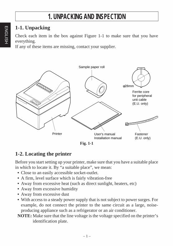
1. UNPACKING AND INSPECTION1-1. Unpacking
Check each item in the box against Figure 1-1 to make sure that you haveeverything.If any of these items are missing, contact your supplier.
Fig. 1-1
1-2. Locating the printer
Before you start setting up your printer, make sure that you have a suitable placein which to locate it. By “a suitable place”, we mean:• Close to an easily accessible socket-outlet.• A firm, level surface which is fairly vibration-free• Away from excessive heat (such as direct sunlight, heaters, etc)• Away from excessive humidity• Away from excessive dust• With access to a steady power supply that is not subject to power surges. For
example, do not connect the printer to the same circuit as a large, noise-producing appliance such as a refrigerator or an air conditioner.
NOTE: Make sure that the line voltage is the voltage specified on the printer’sidentification plate.
φ28mm
Sample paper roll
Ferrite corefor peripheralunit cable(E.U. only)
Fastener(E.U. only)
Printer User's manualInstallation manual
– 2 –
EN
GLI
SH
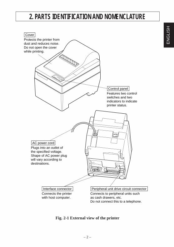
2. PARTS IDENTIFICATION AND NOMENCLATURE
Fig. 2-1 External view of the printer
Features two controlswitches and twoindicators to indicateprinter status.
Control panel
Plugs into an outlet ofthe specified voltage.Shape of AC power plugwill vary according todestinations.
AC power cord
Connects the printerwith host computer.
Interface connectorConnects to peripheral units suchas cash drawers, etc.Do not connect this to a telephone.
Peripheral unit drive circuit connector
Protects the printer from dust and reduces noise.Do not open the coverwhile printing.
Cover
– 3 –
EN
GLIS
H
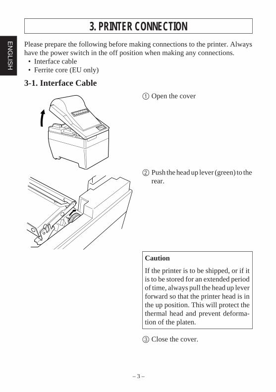
3. PRINTER CONNECTIONPlease prepare the following before making connections to the printer. Alwayshave the power switch in the off position when making any connections.• Interface cable• Ferrite core (EU only)
3-1. Interface Cable
1 Open the cover
2 Push the head up lever (green) to therear.
Caution
If the printer is to be shipped, or if itis to be stored for an extended periodof time, always pull the head up leverforward so that the printer head is inthe up position. This will protect thethermal head and prevent deforma-tion of the platen.
3 Close the cover.
– 4 –
EN
GLI
SH
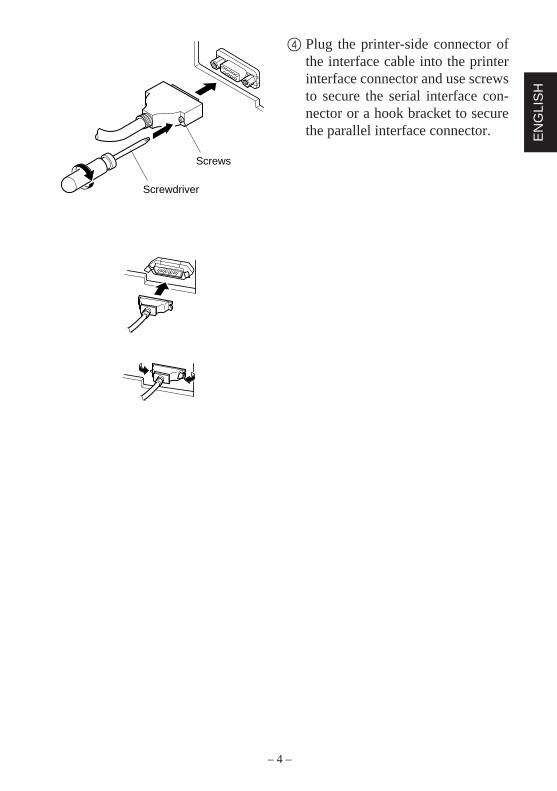
4 Plug the printer-side connector ofthe interface cable into the printerinterface connector and use screwsto secure the serial interface con-nector or a hook bracket to securethe parallel interface connector.
Screws
Screwdriver
– 5 –
EN
GLIS
H
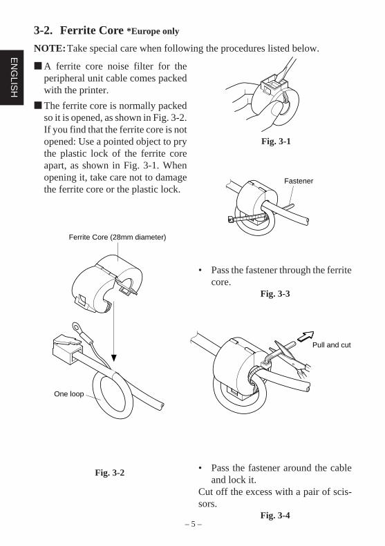
3-2. Ferrite Core *Europe only
NOTE: Take special care when following the procedures listed below.
• Pass the fastener through the ferritecore.
Fig. 3-3
• Pass the fastener around the cableand lock it.
Cut off the excess with a pair of scis-sors.
Fig. 3-4
Fig. 3-1
Fig. 3-2
A ferrite core noise filter for theperipheral unit cable comes packedwith the printer.
The ferrite core is normally packedso it is opened, as shown in Fig. 3-2.If you find that the ferrite core is notopened: Use a pointed object to prythe plastic lock of the ferrite coreapart, as shown in Fig. 3-1. Whenopening it, take care not to damagethe ferrite core or the plastic lock.
Fastener
Pull and cut
One loop
Ferrite Core (28mm diameter)
– 6 –
EN
GLI
SH
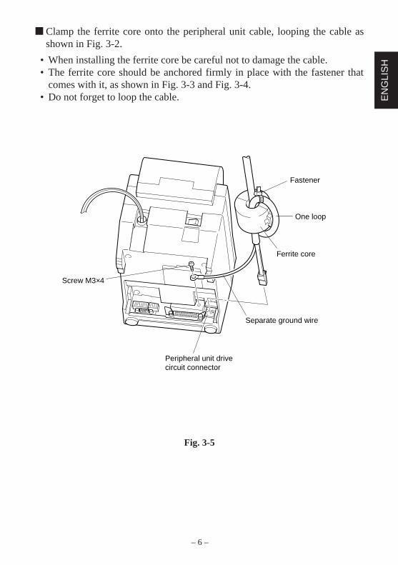
Clamp the ferrite core onto the peripheral unit cable, looping the cable asshown in Fig. 3-2.
• When installing the ferrite core be careful not to damage the cable.• The ferrite core should be anchored firmly in place with the fastener that
comes with it, as shown in Fig. 3-3 and Fig. 3-4.• Do not forget to loop the cable.
Fig. 3-5
Fastener
One loop
Ferrite core
Separate ground wire
Peripheral unit drivecircuit connector
Screw M3×4
– 7 –
EN
GLIS
H
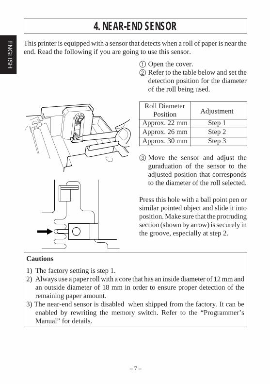
4. NEAR-END SENSORThis printer is equipped with a sensor that detects when a roll of paper is near theend. Read the following if you are going to use this sensor.
1 Open the cover.2 Refer to the table below and set the
detection position for the diameterof the roll being used.
Roll DiameterAdjustmentPosition
Approx. 22 mm Step 1Approx. 26 mm Step 2Approx. 30 mm Step 3
3 Move the sensor and adjust theguraduation of the sensor to theadjusted position that correspondsto the diameter of the roll selected.
Press this hole with a ball point pen orsimilar pointed object and slide it intoposition. Make sure that the protrudingsection (shown by arrow) is securely inthe groove, especially at step 2.
Cautions
1) The factory setting is step 1.2) Always use a paper roll with a core that has an inside diameter of 12 mm and
an outside diameter of 18 mm in order to ensure proper detection of theremaining paper amount.
3) The near-end sensor is disabled when shipped from the factory. It can beenabled by rewriting the memory switch. Refer to the “Programmer’sManual” for details.

TABLE DES MATIÈRES1. DÉBALLAGE ET INSPECTION .........................................................9
1-1. Déballage .....................................................................................91-2. Emplacement de l’imprimante .....................................................9
2. IDENTIFICATION DES PIÈCES ET NOMENCLATURE .............. 10
3. CONNEXION DE L’IMPRIMANTE .................................................113-1. Câble d’interface ........................................................................ 113-2. Tore de ferrite *Uniquement pour l’Europe .............................. 13
4. CAPTEUR DE FIN DE ROULEAU ...................................................15
APPENDICE ...........................................................................................32
L’appendice n’est pas traduit.
– 9 –
FR
AN
ÇA
IS
1. DÉBALLAGE ET INSPECTION1-1. Déballage
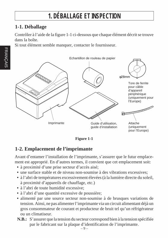
Contrôler à l’aide de la figure 1-1 ci-dessous que chaque élément décrit se trouvedans la boîte.Si tout élément semble manquer, contacter le fournisseur.
Figure 1-1
1-2. Emplacement de l’imprimante
Avant d’entamer l’installation de l’imprimante, s’assurer que le futur emplace-ment est approprié. En d’autres termes, il convient que cet emplacement soit:• à proximité d’une prise secteur d’accès aisé;• une surface stable et de niveau non-soumise à des vibrations excessives;• à l’abri de températures excessivement élevées (à la lumière directe du soleil,
à proximité d’appareils de chauffage, etc.)• à l’abri de toute humidité excessive;• à l’abri d’une quantité excessive de poussière;• alimenté par une source secteur non-soumise à de brusques variations de
tension. Ainsi, ne pas alimenter l’imprimante via un circuit alimentant déjà ungros consommateur de courant et producteur de bruit tel qu’un réfrigérateurou un climatiseur.
N.B.: S’assurer que la tension du secteur correspond bien à la tension spécifiéepar le fabricant sur la plaque d’identification de l’imprimante.
φ28mm
Sample paper roll
Ferrite corefor peripheralunit cable(E.U. only)
Fastener(E.U. only)
Printer User's manualInstallation manual
Imprimante
Echantillon de rouleau de papier
Tore de ferritepour câbled’appareilpériphérique(uniquement pourl’Europe)
Guide d’utilisation,guide d’installation
Attache(uniquementpour l’Europe)
– 10 –
FR
AN
ÇA
IS
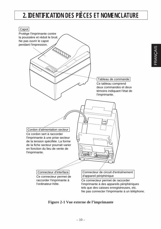
Ce tableau comprend deux commandes et deux témoins indiquant l'état de l'imprimante.
Tableau de commande
Ce cordon sert à raccorder l'imprimante à une prise secteur de la tension spécifiée. La forme de la fiche secteur pourrait varier en fonction du lieu de vente de l'imprimante.
Cordon d'alimentation secteur
Ce connecteur permet de raccorder l'imprimante à l'ordinateur-hôte.
Connecteur d'interface
Ce connecteur permet de raccorder l'imprimante à des appareils périphériques tels que des caisses enregistreuses, etc.Ne pas connecter l'imprimante à un téléphone.
Connecteur de circuit d'entraînement d'appareil périphérique
Protège l'imprimante contre la poussière et réduit le bruit. Ne pas ouvrir le capot pendant l'impression.
Capot
2. IDENTIFICATION DES PIÈCES ET NOMENCLATURE
Figure 2-1 Vue externe de l’imprimante
– 11 –
FR
AN
ÇA
IS
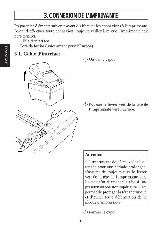
3. CONNEXION DE L’IMPRIMANTEPréparer les éléments suivants avant d’effectuer les connexions à l’imprimante.Avant d’effectuer toute connexion, toujours veiller à ce que l’imprimante soithors tension.• Câble d’interface• Tore de ferrite (uniquement pour l’Europe)
3-1. Câble d’interface1 Ouvrir le capot.
2 Pousser le levier vert de la tête del’imprimante vers l’arrière.
Attention
Si l’imprimante doit être expédiée ourangée pour une période prolongée,s’assurer de toujours tirer le leviervert de la tête de l’imprimante versl’avant afin d’amener la tête d’im-pression en position supérieure. Cecipermet de protéger la tête thermiqueet d’éviter toute déformation de laplaque d’impression.
3 Fermer le capot.
– 12 –
FR
AN
ÇA
IS
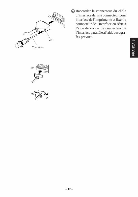
4 Raccorder le connecteur du câbled’interface dans le connecteur pourinterface de l’imprimante et fixer leconnecteur de l’interface en série àl’aide de vis ou le connecteur del’interface parallèle à l’aide des agra-fes prévues.
Screws
Screwdriver
Vis
Tournevis
– 13 –
FR
AN
ÇA
IS
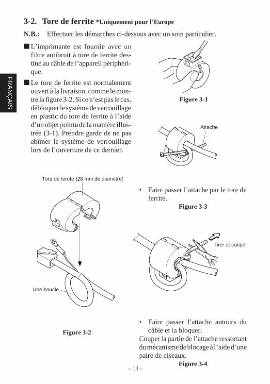
3-2. Tore de ferrite *Uniquement pour l’Europe
N.B.: Effectuer les démarches ci-dessous avec un soin particulier.
• Faire passer l’attache par le tore deferrite.
Figure 3-3
Figure 3-1
Figure 3-2
L’imprimante est fournie avec unfiltre antibruit à tore de ferrite des-tiné au câble de l’appareil périphéri-que.
Le tore de ferrite est normalementouvert à la livraison, comme le mon-tre la figure 3-2. Si ce n’est pas le cas,débloquer le système de verrouillageen plastic du tore de ferrite à l’aided’un objet pointu de la manière illus-trée (3-1). Prendre garde de ne pasabîmer le système de verrouillagelors de l’ouverture de ce dernier.
Fastener
Pull and cut
One loop
Ferrite Core (28mm diameter)
• Faire passer l’attache autours ducâble et la bloquer.
Couper la partie de l’attache ressortantdu mécanisme de blocage à l’aide d’unepaire de ciseaux.
Figure 3-4
Tore de ferrite (28 mm de diamètre)
Une boucle
Attache
Tirer et couper
– 14 –
FR
AN
ÇA
IS
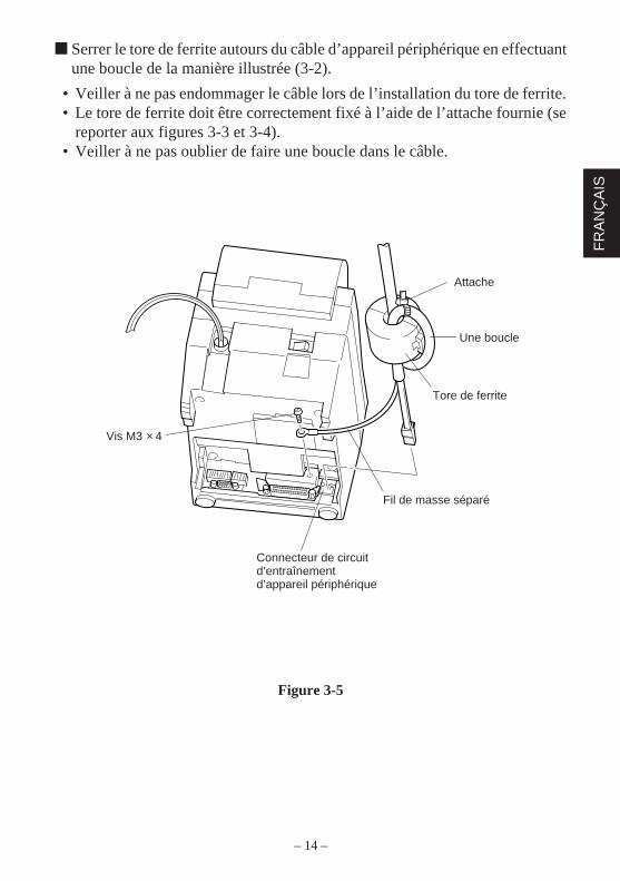
Serrer le tore de ferrite autours du câble d’appareil périphérique en effectuantune boucle de la manière illustrée (3-2).
• Veiller à ne pas endommager le câble lors de l’installation du tore de ferrite.• Le tore de ferrite doit être correctement fixé à l’aide de l’attache fournie (se
reporter aux figures 3-3 et 3-4).• Veiller à ne pas oublier de faire une boucle dans le câble.
Figure 3-5
Fastener
One loop
Ferrite core
Separate ground wire
Peripheral unit drivecircuit connector
Screw M3×4Vis M3 × 4
Attache
Une boucle
Tore de ferrite
Fil de masse séparé
Connecteur de circuitd’entraînementd’appareil périphérique
– 15 –
FR
AN
ÇA
IS
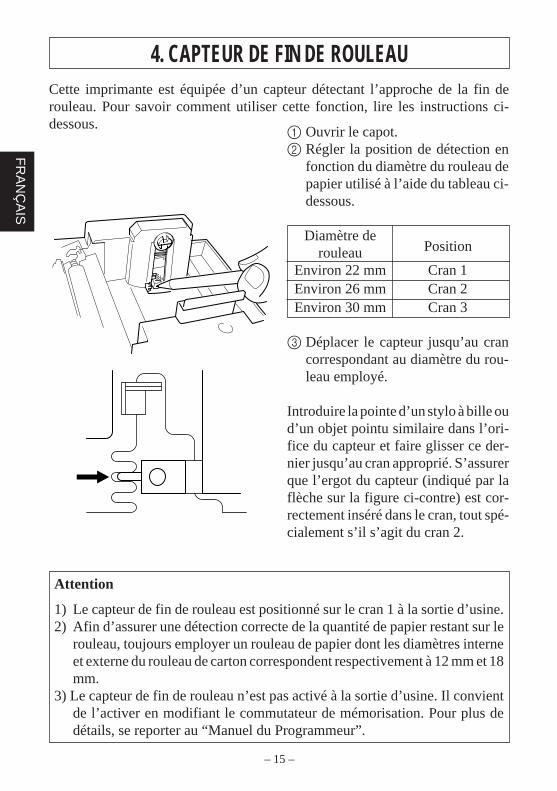
4. CAPTEUR DE FIN DE ROULEAUCette imprimante est équipée d’un capteur détectant l’approche de la fin derouleau. Pour savoir comment utiliser cette fonction, lire les instructions ci-dessous.
1 Ouvrir le capot.2 Régler la position de détection en
fonction du diamètre du rouleau depapier utilisé à l’aide du tableau ci-dessous.
Diamètre dePositionrouleau
Environ 22 mm Cran 1Environ 26 mm Cran 2Environ 30 mm Cran 3
3 Déplacer le capteur jusqu’au crancorrespondant au diamètre du rou-leau employé.
Introduire la pointe d’un stylo à bille oud’un objet pointu similaire dans l’ori-fice du capteur et faire glisser ce der-nier jusqu’au cran approprié. S’assurerque l’ergot du capteur (indiqué par laflèche sur la figure ci-contre) est cor-rectement inséré dans le cran, tout spé-cialement s’il s’agit du cran 2.
Attention
1) Le capteur de fin de rouleau est positionné sur le cran 1 à la sortie d’usine.2) Afin d’assurer une détection correcte de la quantité de papier restant sur le
rouleau, toujours employer un rouleau de papier dont les diamètres interneet externe du rouleau de carton correspondent respectivement à 12 mm et 18mm.
3) Le capteur de fin de rouleau n’est pas activé à la sortie d’usine. Il convientde l’activer en modifiant le commutateur de mémorisation. Pour plus dedétails, se reporter au “Manuel du Programmeur”.

INHALTSVERZEICHNIS1. AUSPACKEN UND PRÜFUNG ........................................................ 17
1-1. Auspacken .................................................................................. 171-2. Wahl eines Aufstellungsorts ...................................................... 17
2. FUNKTION UND BEZEICHNUNG DER TEILE ............................ 18
3. DRUCKERVERBINDUNG................................................................ 193-1. Schnittstellenkabel .....................................................................193-2. Ferritkern *nur Europa .................................................................................21
4. PAPIERVORRAT-SENSOR .............................................................. 23
ANHANG ................................................................................................ 32
Der Anhang erscheint nur im englischen Teil dieser Bedienungsanleitung
– 17 –
DE
UT
SC
H
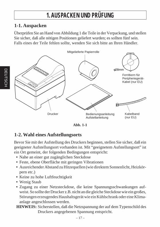
1. AUSPACKEN UND PRÜFUNG1-1. Auspacken
Überprüfen Sie an Hand von Abbildung 1 die Teile in der Verpackung, und stellenSie sicher, daß alle nötigen Positionen geliefert wurden; es sollten fünf sein.Falls eines der Teile fehlen sollte, wenden Sie sich bitte an Ihren Händler.
Abb. 1-1
1-2. Wahl eines Aufstellungsorts
Bevor Sie mit der Aufstellung des Druckers beginnen, stellen Sie sicher, daß eingeeigneter Aufstellungsort vorhanden ist. Mit “geeignetem Aufstellungsort” istein Ort gemeint, der folgenden Bedingungen entspricht:• Nahe an einer gut zugänglichen Steckdose• Feste, ebene Oberfläche mit geringen Vibrationen• Ausreichender Abstand zu Hitzequellen (wie direktem Sonnenlicht, Heizkör-
pern etc.)• Keine zu hohe Luftfeuchtigkeit• Wenig Staub• Zugang zu einer Netzsteckdose, die keine Spannungsschwankungen auf-
weist. So sollte der Drucker z.B. nicht an die gleiche Steckdose wie ein großes,Störungen erzeugendes Haushaltsgerät wie ein Kühlschrank oder eine Klima-anlage angeschlossen werden.
HINWEIS: Sicherstellen, daß die Netzspannung der auf dem Typenschild desDruckers angegebenen Spannung entspricht.
φ28mm
Sample paper roll
Ferrite corefor peripheralunit cable(E.U. only)
Fastener(E.U. only)
Printer User's manualInstallation manual
Mitgelieferte Papierrolle
Ferritkern fürPeripheriegerät-Kabel (nur EU)
Kabelband(nur EU)
Drucker BedienungsanleitungAufstellanleitung
– 18 –
DE
UT
SC
H
2. FUNKTION UND BEZEICHNUNG DER TEILE
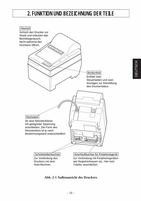
Abb. 2-1 Außenansicht des Druckers
Enthält zwei Steuertasten und zwei Anzeigen zur Darstellung des Druckerstatus.
Bedienfeld
An eine Netzsteckdose mit geeigneter Spannung anschließen. Die Form des Netzsteckers ist je nach Bestimmungsland unterschiedlich.
Netzkabel
Zur Verbindung des Druckers mit dem Host-Rechner.
SchnittstellenbuchseZur Verbindung mit Peripheriegeräten wie Registrierkassen etc. Hier kein Telefon anschließen.
Anschlußbuchse für Peripheriegerät
Schützt den Drucker vor Staub und reduziert das Betriebsgeräusch.Nicht während des Druckens öffnen.
Oberteil
– 19 –
DE
UT
SC
H
3. DRUCKERVERBINDUNGVor dem Herstellen von Verbindungen folgende Vorbereitungen treffen. ImmerNetzschalter in Aus-Stellung stellen, während Verbindungen hergestellt werden.• Schnittstellenkabel• Ferritkern (nur EU)
3-1. Schnittstellenkabel
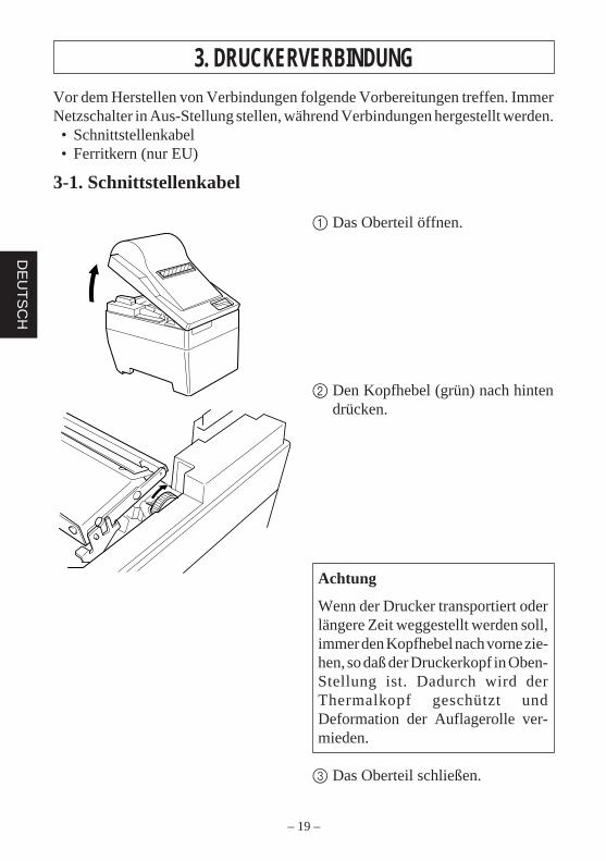
1 Das Oberteil öffnen.
2 Den Kopfhebel (grün) nach hintendrücken.
Achtung
Wenn der Drucker transportiert oderlängere Zeit weggestellt werden soll,immer den Kopfhebel nach vorne zie-hen, so daß der Druckerkopf in Oben-Stellung ist. Dadurch wird derThermalkopf geschützt undDeformation der Auflagerolle ver-mieden.
3 Das Oberteil schließen.
– 20 –
DE
UT
SC
H
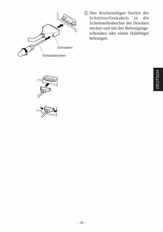
4 Den druckerseitigen Stecker desSchnittstellenkabels in dieSchnittstellenbuchse des Druckersstecken und mit den Befestigungs-schrauben oder einem Haltebügelbefestigen.
Screws
Screwdriver
Schrauben
Schraubenzieher
– 21 –
DE
UT
SC
H
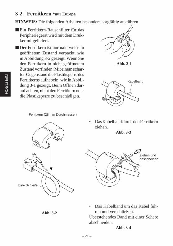
3-2. Ferritkern *nur Europa
HINWEIS: Die folgenden Arbeiten besonders sorgfältig ausführen.
• Das Kabelband durch den Ferritkernziehen.
Abb. 3-3
Abb. 3-1
Abb. 3-2
Ein Ferritkern-Rauschfilter für dasPeripheriegerät wird mit dem Druk-ker mitgeliefert.
Der Ferritkern ist normalerweise ingeöffnetem Zustand verpackt, wiein Abbildung 3-2 gezeigt. Wenn Sieden Ferritkern in nicht geöffnetemZustand vorfinden: Mit einem schar-fen Gegenstand die Plastiksperre desFerritkerns aufhebeln, wie in Abbil-dung 3-1 gezeigt. Beim Öffnen dar-auf achten, nicht den Ferritkern oderdie Plastiksperre zu beschädigen.
Fastener
Pull and cut
One loop
Ferrite Core (28mm diameter)
• Das Kabelband um das Kabel füh-ren und verschließen.
Überstehendes Band mit einer Schereabschneiden.
Abb. 3-4
Ferritkern (28 mm Durchmesser)
Eine Schleife
Kabelband
Ziehen undabschneiden
– 22 –
DE
UT
SC
H
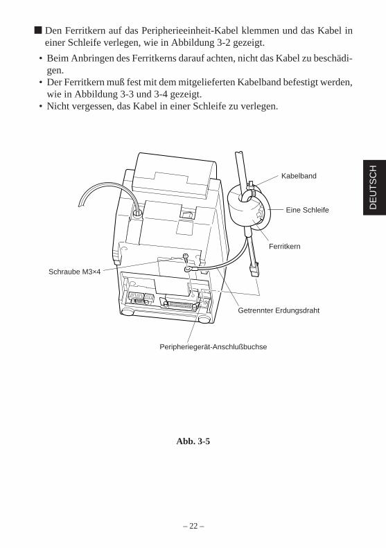
Den Ferritkern auf das Peripherieeinheit-Kabel klemmen und das Kabel ineiner Schleife verlegen, wie in Abbildung 3-2 gezeigt.
• Beim Anbringen des Ferritkerns darauf achten, nicht das Kabel zu beschädi-gen.
• Der Ferritkern muß fest mit dem mitgelieferten Kabelband befestigt werden,wie in Abbildung 3-3 und 3-4 gezeigt.
• Nicht vergessen, das Kabel in einer Schleife zu verlegen.
Abb. 3-5
Fastener
One loop
Ferrite core
Separate ground wire
Peripheral unit drivecircuit connector
Screw M3×4Schraube M3×4
Peripheriegerät-Anschlußbuchse
Kabelband
Eine Schleife
Getrennter Erdungsdraht
Ferritkern
– 23 –
DE
UT
SC
H
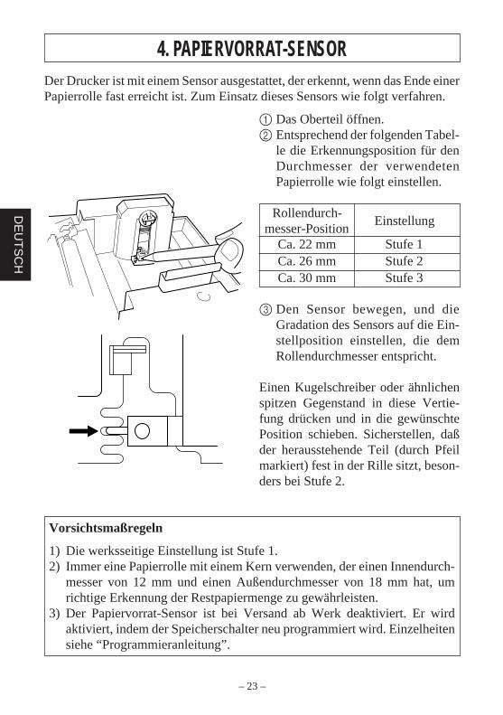
4. PAPIERVORRAT-SENSORDer Drucker ist mit einem Sensor ausgestattet, der erkennt, wenn das Ende einerPapierrolle fast erreicht ist. Zum Einsatz dieses Sensors wie folgt verfahren.
Vorsichtsmaßregeln
1) Die werksseitige Einstellung ist Stufe 1.2) Immer eine Papierrolle mit einem Kern verwenden, der einen Innendurch-
messer von 12 mm und einen Außendurchmesser von 18 mm hat, umrichtige Erkennung der Restpapiermenge zu gewährleisten.
3) Der Papiervorrat-Sensor ist bei Versand ab Werk deaktiviert. Er wirdaktiviert, indem der Speicherschalter neu programmiert wird. Einzelheitensiehe “Programmieranleitung”.
1 Das Oberteil öffnen.2 Entsprechend der folgenden Tabel-
le die Erkennungsposition für denDurchmesser der verwendetenPapierrolle wie folgt einstellen.
Rollendurch-Einstellung
messer-PositionCa. 22 mm Stufe 1Ca. 26 mm Stufe 2Ca. 30 mm Stufe 3
3 Den Sensor bewegen, und dieGradation des Sensors auf die Ein-stellposition einstellen, die demRollendurchmesser entspricht.
Einen Kugelschreiber oder ähnlichenspitzen Gegenstand in diese Vertie-fung drücken und in die gewünschtePosition schieben. Sicherstellen, daßder herausstehende Teil (durch Pfeilmarkiert) fest in der Rille sitzt, beson-ders bei Stufe 2.

INDICE1. APERTURA E CONTROLLO DELLA CONFEZIONE ...................25
1-1. Apertura della confezione .......................................................... 251-2. Scelta del luogo di installazione della stampante .......................25
2. IDENTIFICAZIONE E NOMENCLATURA DELLE PARTI .......... 26
3. COLLEGAMENTO DELLA STAMPANTE .....................................273-1. Cavo di interfaccia .....................................................................273-2. Anello di ferrite *solo per l’Europa ...........................................29
4. SENSORE DI RILEVAMENTO FINE CARTA ................................ 31
APPENDICE ...........................................................................................32
L’Appendice appare solo nella sezione in inglese di questo manuale.
– 25 –
ITA
LIAN
O
1. APERTURA E CONTROLLO DELLA CONFEZIONE1-1. Apertura della confezione
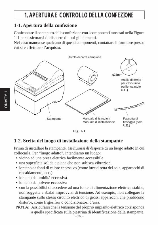
Confrontare il contenuto della confezione con i componenti mostrati nella Figura1-1 per assicurarsi di disporre di tutti gli elementi.Nel caso mancasse qualcuno di questi componenti, contattare il fornitore pressocui si è effettuato l’acquisto.
Fig. 1-1
1-2. Scelta del luogo di installazione della stampante
Prima di installare la stampante, assicurarsi di disporre di un luogo adatto in cuicollocarla. Per “luogo adatto”, intendiamo un luogo:• vicino ad una presa elettrica facilmente accessibile• una superficie solida e piana che non subisca vibrazioni• lontano da fonti di calore eccessivo (come luce diretta del sole, apparecchi di
riscaldamento, ecc.)• lontano da umidità eccessiva• lontano da polvere eccessiva• con la possibilità di accedere ad una fonte di alimentazione elettrica stabile,
non soggetta a sbalzi improvvisi di tensione. Ad esempio, non collegare lastampante sullo stesso circuito elettrico di grossi apparecchi che produconodisturbi, come frigoriferi o condizionatori d’aria.
NOTA: Assicurarsi che la tensione del proprio impianto elettrico corrispondaa quella specificata sulla piastrina di identificazione della stampante.
φ28mm
Sample paper roll
Ferrite corefor peripheralunit cable(E.U. only)
Fastener(E.U. only)
Printer User's manualInstallation manual
Rotolo di carta campione
Anello di ferriteper cavo unitàperiferica (soloU.E.)
Stampante Manuale di istruzioniManuale di installazione
Fascetta difissaggio (soloU.E.)
– 26 –
ITA
LIA
NO
2. IDENTIFICAZIONE E NOMENCLATURA DELLE PARTI
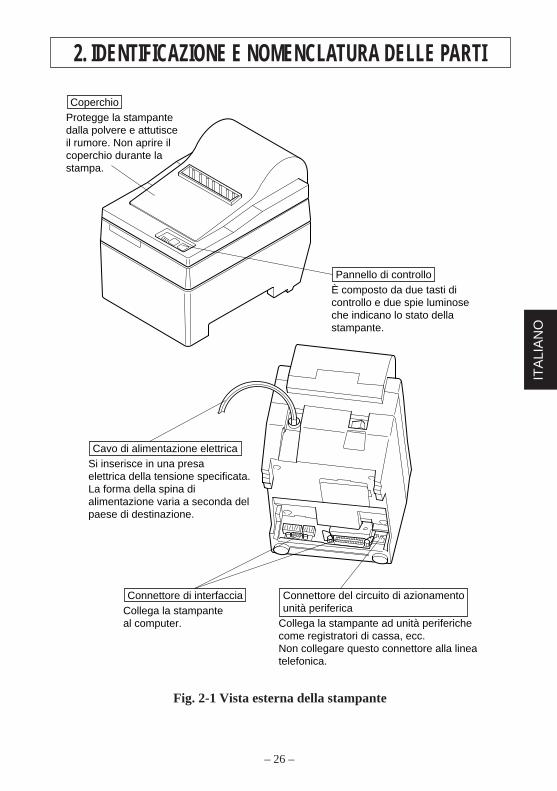
Fig. 2-1 Vista esterna della stampante
È composto da due tasti di controllo e due spie luminose che indicano lo stato della stampante.
Pannello di controllo
Si inserisce in una presa elettrica della tensione specificata. La forma della spina di alimentazione varia a seconda del paese di destinazione.
Cavo di alimentazione elettrica
Collega la stampante al computer.
Connettore di interfaccia
Collega la stampante ad unità periferiche come registratori di cassa, ecc.Non collegare questo connettore alla linea telefonica.
Connettore del circuito di azionamento unità periferica
Protegge la stampante dalla polvere e attutisce il rumore. Non aprire il coperchio durante la stampa.
Coperchio
– 27 –
ITA
LIAN
O
3. COLLEGAMENTO DELLA STAMPANTETenere pronti i seguenti componenti prima di effettuare i collegamenti dellastampante. Spegnere sempre l’interruttore di alimentazione prima di effettuarequalunque collegamento.• Cavo di interfaccia• Anello di ferrite (solo U.E.)
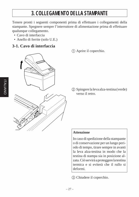
3-1. Cavo di interfaccia1 Aprire il coperchio.
2 Spingere la leva alza-testina (verde)verso il retro.
Attenzione
In caso di spedizione della stampanteo di conservazione per un lungo peri-odo di tempo, tirare sempre in avantila leva alza-testina in modo che latestina di stampa sia in posizione al-zata. Ciò servirà a proteggere la testinatermica e si eviterà che il rullo sideformi.
3 Chiudere il coperchio.
– 28 –
ITA
LIA
NO
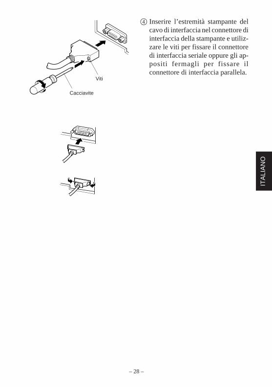
4 Inserire l’estremità stampante delcavo di interfaccia nel connettore diinterfaccia della stampante e utiliz-zare le viti per fissare il connettoredi interfaccia seriale oppure gli ap-positi fermagli per fissare ilconnettore di interfaccia parallela.
Screws
Screwdriver
Viti
Cacciavite
– 29 –
ITA
LIAN
O
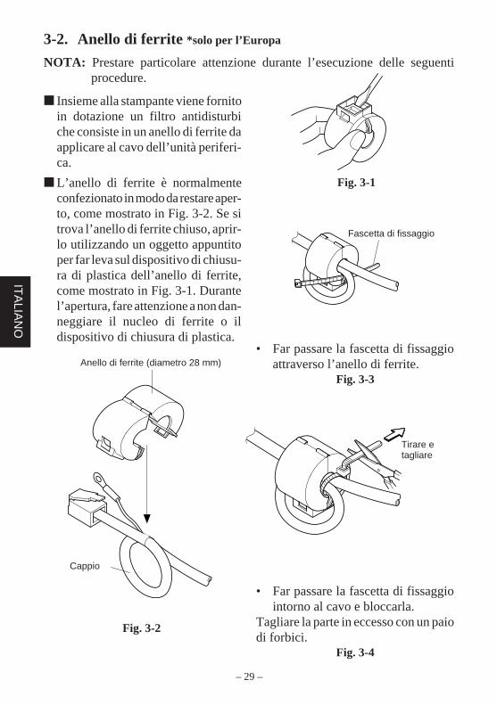
3-2. Anello di ferrite *solo per l’Europa
NOTA: Prestare particolare attenzione durante l’esecuzione delle seguentiprocedure.
• Far passare la fascetta di fissaggioattraverso l’anello di ferrite.
Fig. 3-3
Fig. 3-1
Insieme alla stampante viene fornitoin dotazione un filtro antidisturbiche consiste in un anello di ferrite daapplicare al cavo dell’unità periferi-ca.
L’anello di ferrite è normalmenteconfezionato in modo da restare aper-to, come mostrato in Fig. 3-2. Se sitrova l’anello di ferrite chiuso, aprir-lo utilizzando un oggetto appuntitoper far leva sul dispositivo di chiusu-ra di plastica dell’anello di ferrite,come mostrato in Fig. 3-1. Durantel’apertura, fare attenzione a non dan-neggiare il nucleo di ferrite o ildispositivo di chiusura di plastica.
Fastener
Pull and cut
• Far passare la fascetta di fissaggiointorno al cavo e bloccarla.
Tagliare la parte in eccesso con un paiodi forbici.
Fig. 3-4
One loop
Ferrite Core (28mm diameter)
Fig. 3-2
Cappio
Anello di ferrite (diametro 28 mm)
Fascetta di fissaggio
Tirare etagliare
– 30 –
ITA
LIA
NO
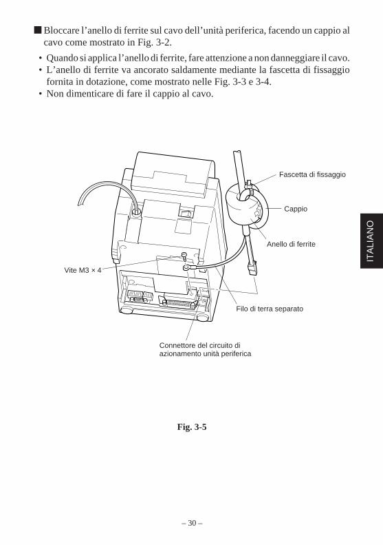
Bloccare l’anello di ferrite sul cavo dell’unità periferica, facendo un cappio alcavo come mostrato in Fig. 3-2.
• Quando si applica l’anello di ferrite, fare attenzione a non danneggiare il cavo.• L’anello di ferrite va ancorato saldamente mediante la fascetta di fissaggio
fornita in dotazione, come mostrato nelle Fig. 3-3 e 3-4.• Non dimenticare di fare il cappio al cavo.
Fig. 3-5
Fastener
One loop
Ferrite core
Separate ground wire
Peripheral unit drivecircuit connector
Screw M3×4Vite M3 × 4
Fascetta di fissaggio
Anello di ferrite
Connettore del circuito diazionamento unità periferica
Filo di terra separato
Cappio
– 31 –
ITA
LIAN
O
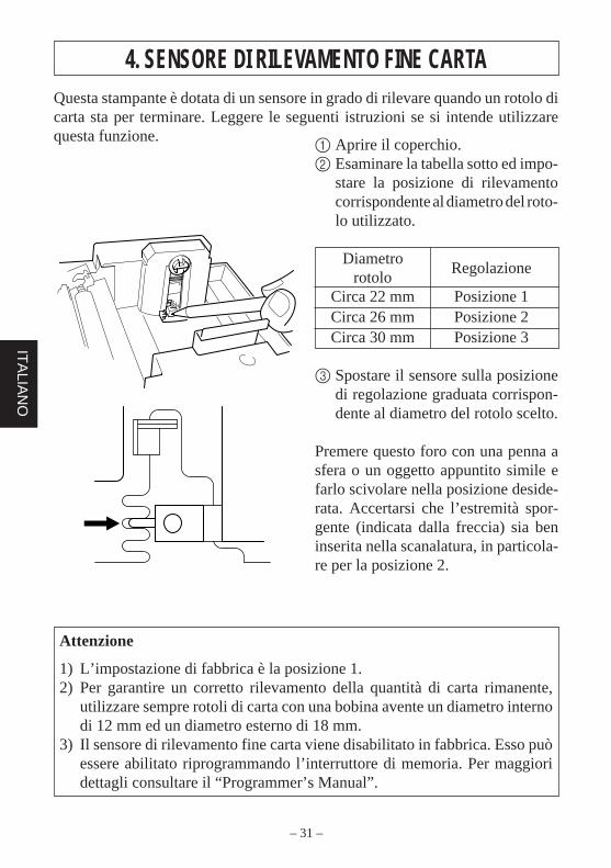
4. SENSORE DI RILEVAMENTO FINE CARTAQuesta stampante è dotata di un sensore in grado di rilevare quando un rotolo dicarta sta per terminare. Leggere le seguenti istruzioni se si intende utilizzarequesta funzione.
Attenzione
1) L’impostazione di fabbrica è la posizione 1.2) Per garantire un corretto rilevamento della quantità di carta rimanente,
utilizzare sempre rotoli di carta con una bobina avente un diametro internodi 12 mm ed un diametro esterno di 18 mm.
3) Il sensore di rilevamento fine carta viene disabilitato in fabbrica. Esso puòessere abilitato riprogrammando l’interruttore di memoria. Per maggioridettagli consultare il “Programmer’s Manual”.
1 Aprire il coperchio.2 Esaminare la tabella sotto ed impo-
stare la posizione di rilevamentocorrispondente al diametro del roto-lo utilizzato.
DiametroRegolazione
rotoloCirca 22 mm Posizione 1Circa 26 mm Posizione 2Circa 30 mm Posizione 3
3 Spostare il sensore sulla posizionedi regolazione graduata corrispon-dente al diametro del rotolo scelto.
Premere questo foro con una penna asfera o un oggetto appuntito simile efarlo scivolare nella posizione deside-rata. Accertarsi che l’estremità spor-gente (indicata dalla freccia) sia beninserita nella scanalatura, in particola-re per la posizione 2.
– 32 –
AP
PE
ND
IX
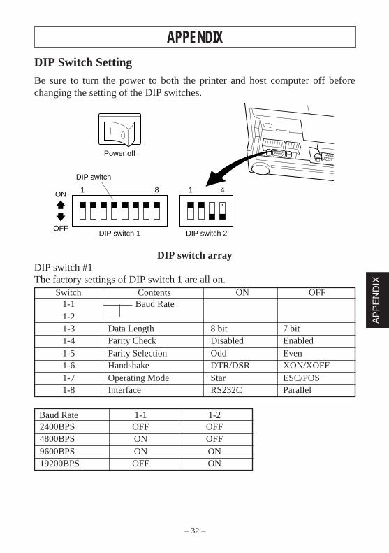
APPENDIXDIP Switch Setting
Be sure to turn the power to both the printer and host computer off beforechanging the setting of the DIP switches.
DIP switch arrayDIP switch #1The factory settings of DIP switch 1 are all on.
Switch Contents ON OFF1-1 Baud Rate1-21-3 Data Length 8 bit 7 bit1-4 Parity Check Disabled Enabled1-5 Parity Selection Odd Even1-6 Handshake DTR/DSR XON/XOFF1-7 Operating Mode Star ESC/POS1-8 Interface RS232C Parallel
Baud Rate 1-1 1-22400BPS OFF OFF4800BPS ON OFF9600BPS ON ON19200BPS OFF ON
81 41ON
OFFDIP switch 1
DIP switch
DIP switch 2
Power off
– 33 –
AP
PE
ND
IX
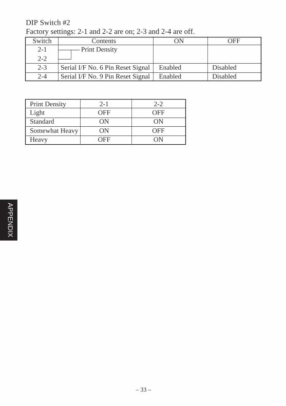
DIP Switch #2Factory settings: 2-1 and 2-2 are on; 2-3 and 2-4 are off.
Switch Contents ON OFF2-1 Print Density2-22-3 Serial I/F No. 6 Pin Reset Signal Enabled Disabled2-4 Serial I/F No. 9 Pin Reset Signal Enabled Disabled
Print Density 2-1 2-2Light OFF OFFStandard ON ONSomewhat Heavy ON OFFHeavy OFF ON
– 34 –
AP
PE
ND
IX
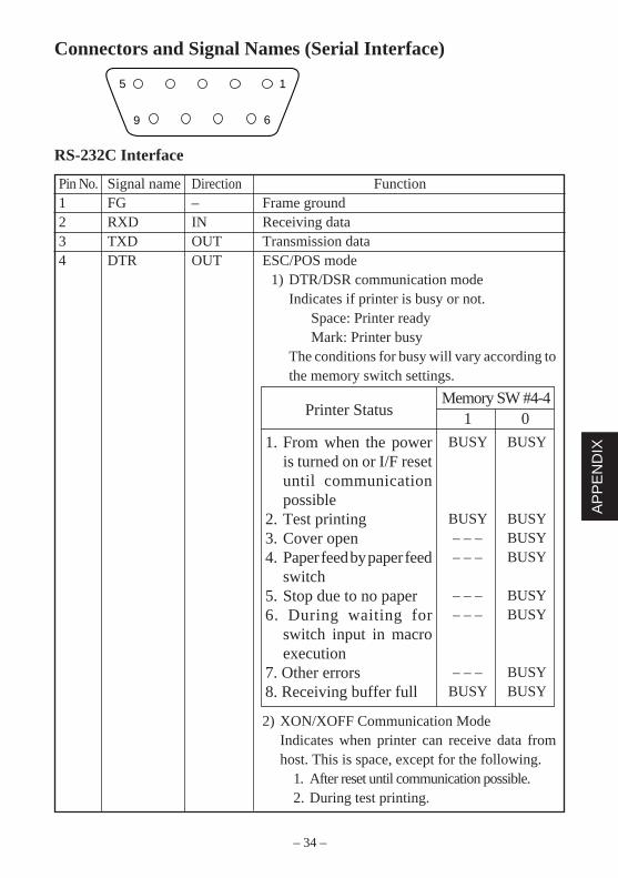
Connectors and Signal Names (Serial Interface)
RS-232C Interface
Pin No. Signal name Direction Function1 FG – Frame ground2 RXD IN Receiving data3 TXD OUT Transmission data4 DTR OUT ESC/POS mode
1) DTR/DSR communication modeIndicates if printer is busy or not.
Space: Printer readyMark: Printer busy
The conditions for busy will vary according tothe memory switch settings.
2) XON/XOFF Communication ModeIndicates when printer can receive data fromhost. This is space, except for the following.
1. After reset until communication possible.2. During test printing.
5 1
69
1. From when the poweris turned on or I/F resetuntil communicationpossible
2. Test printing3. Cover open4. Paper feed by paper feed
switch5. Stop due to no paper6. During waiting for
switch input in macroexecution
7. Other errors8. Receiving buffer full
BUSY BUSY
BUSY BUSY– – – BUSY– – – BUSY
– – – BUSY– – – BUSY
– – – BUSYBUSY BUSY
Memory SW #4-41 0Printer Status
– 35 –
AP
PE
ND
IX
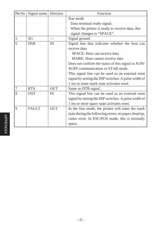
Pin No. Signal name Direction FunctionStar mode
Data terminal ready signal.When the printer is ready to receive data, thissignal changes to “SPACE”.
5 SG — Signal ground6 DSR IN Signal line that indicates whether the host can
receive dataSPACE: Host can receive dataMARK: Host cannot receive data
Does not confirm the status of this signal in XON/XOFF communication or STAR mode.This signal line can be used as an external resetsignal by setting the DIP switches. A pulse width of1 ms or more mark state activates reset.
7 RTS OUT Same as DTR signal.8 INIT IN This signal line can be used as an external reset
signal by setting the DIP switches. A pulse width of1 ms or more space state activates reset.
9 FAULT OUT In the Star mode, the printer will enter the markstate during the following errors: no paper, head up,cutter error. In ESC/POS mode, this is normallyspace.
– 36 –
AP
PE
ND
IX
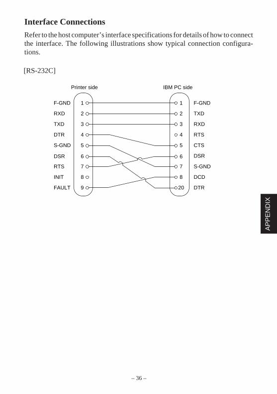
Interface Connections
Refer to the host computer’s interface specifications for details of how to connectthe interface. The following illustrations show typical connection configura-tions.
[RS-232C]
1
2
3
4
5
7
8
9
1
2
3
4
5
6
7
8
20
F-GND
TXD
RXD
RTS
CTS
DSR
S-GND
DCD
DTR
F-GND
RXD
TXD
DTR
S-GND
6DSR
RTS
INIT
FAULT
Printer side IBM PC side
– 37 –
AP
PE
ND
IX
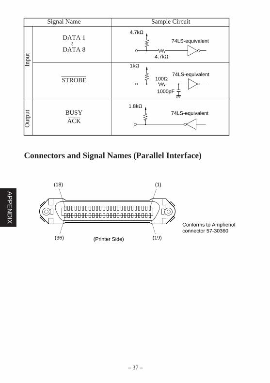
Signal Name Sample CircuitIn
put
Out
put
DATA 1
DATA 8
STROBE
BUSYACK
~
Connectors and Signal Names (Parallel Interface)
4.7kΩ
74LS-equivalent
4.7kΩ
1kΩ
100Ω
1000pF
74LS-equivalent
1.8kΩ74LS-equivalent
(18) (1)
(36) (19)
Conforms to Amphenol connector 57-30360
(Printer Side)
– 38 –
AP
PE
ND
IX
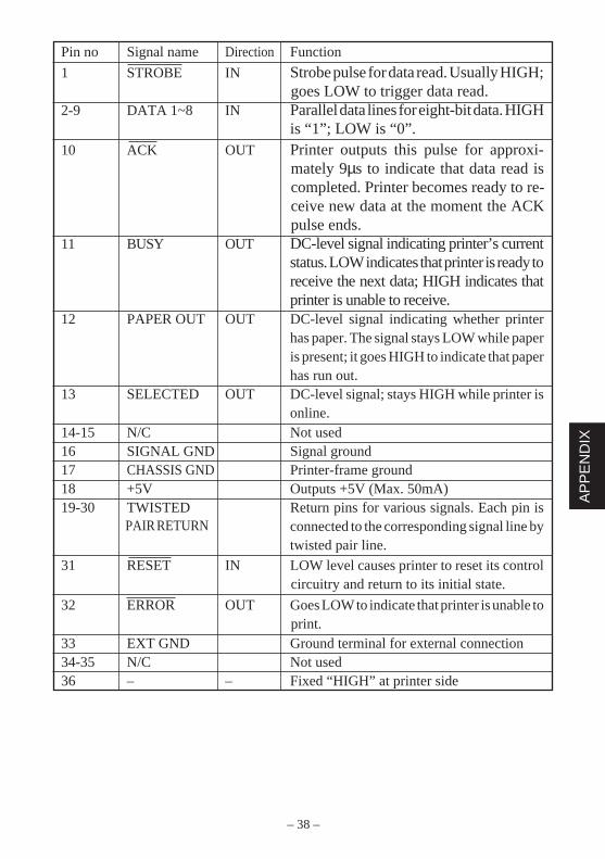
Pin no Signal name Direction Function
1 STROBE IN Strobe pulse for data read. Usually HIGH;goes LOW to trigger data read.
2-9 DATA 1~8 IN Parallel data lines for eight-bit data. HIGHis “1”; LOW is “0”.
10 ACK OUT Printer outputs this pulse for approxi-mately 9µs to indicate that data read iscompleted. Printer becomes ready to re-ceive new data at the moment the ACKpulse ends.
11 BUSY OUT DC-level signal indicating printer’s currentstatus. LOW indicates that printer is ready toreceive the next data; HIGH indicates thatprinter is unable to receive.
12 PAPER OUT OUT DC-level signal indicating whether printerhas paper. The signal stays LOW while paperis present; it goes HIGH to indicate that paperhas run out.
13 SELECTED OUT DC-level signal; stays HIGH while printer isonline.
14-15 N/C Not used16 SIGNAL GND Signal ground17 CHASSIS GND Printer-frame ground18 +5V Outputs +5V (Max. 50mA)19-30 TWISTED Return pins for various signals. Each pin is
connected to the corresponding signal line bytwisted pair line.
31 RESET IN LOW level causes printer to reset its controlcircuitry and return to its initial state.
32 ERROR OUT Goes LOW to indicate that printer is unable toprint.
33 EXT GND Ground terminal for external connection34-35 N/C Not used36 – – Fixed “HIGH” at printer side
PAIR RETURN

– 39 –
AP
PE
ND
IX
Peripheral Unit Drive Circuit
A drive circuit for driving peripheral units (such as cash drawers) is featured onthe main logic board of this printer. A modular connector for driving peripheralunits is featured on the output side on the drive circuit. When using this circuit,connect the cable for the peripheral unit. (Cables must be prepared by the user.)
Use cables which meet the following specifications.1. Use the modular plug as shown in Figure below.2. Separate ground wire is required for Europe only.3. If the printer is used in Europe, the Ferrite core should be attached to the cable,
as shown in Figure below.
CAUTION : DO NOT connect any other plug to the peripheral unit connector.
Cable specifications for peripheral unit.
Separate ground wire and noise filter are required for Europe.
Ferrite core
1 turn
Ground wire
16
Modular plug MOLEX 90075-0007,AMP641337 or JAPAN BURNDY B-66-4
Shield
Wire lead
Separated Ground wireconnected to shield (Europe only).

– 40 –
AP
PE
ND
IX
[Drive output 24V, max. 1.0 A]
Drive circuitThe recommended drive circuit is shown.
NOTES:1. Peripheral units #1 and #2 cannot be driven simultaneously.
When driving a device continuously, do not use drive duty above 20%.2. Compulsion switch status is available as status data.3. Resistance for coils L1 and L2 is not less than 24 ohms.4. Absolute maximum ratings for diodes D1 and D2 (at Ta=25˚C):
Average rectified current Io = 1AMaximum forward surge current (60Hz,1-cycle sine wave) IFSM=40A
5. Absolute maximum rating for transistors TR1 and TR2 (at Ta = 25˚C):Collector current Ic = 2A
7824
F.G
TR1
M-GND
TR2
M-GND
TR3
+5V
+24V
R1
R2
6
5
4
3
2
1
L1
L2
R34.7kΩ1/4W
Frameground
D1
D2
Peripheralunit 1
With shield
Peripheralunit 2
Compulsionswitch

– 41 –
MEMO

– 43 –
MEMO
P 1996.10

Printed in Japan, 80871035
HEAD OFFICESTAR MICRONICS CO., LTD.20-10 Nakayoshida, Shizuoka, 422 JapanTel: 054-263-1115, Fax: 054-263-8714
OVERSEAS SUBSIDIARY COMPANIESSTAR MICRONICS AMERICA, INC.70-D Ethel Road West, Piscataway, NJ 08854 U.S.ATel: 908-572-9512, Fax: 908-572-5095
STAR MICRONICS DEUTSCHLAND GMBHWesterbachstraße 59, D-60489 Frankfurt, GermanyTel: 069-789990, Fax: 069-781006
STAR MICRONICS U.K. LTD.Star House, Peregrine Business Park, Gomm Road,High Wycombe, Bucks, HP13 7DL, U.K.Tel: 01494-471111, Fax: 01494-473333


![ENGLISH DEUTSCH FRANÇAIS ITALIANO Lieber Kunde Cher … · [Configuration appareil]/[Config. d’appareil] → [Aff. infos sur appareil]/[Aff. info d’appareil]. ≥Mettez la version](https://img.pdfslide.us/doc/110x75/5e1cb93ec8c91664312e9886/english-deutsch-franais-italiano-lieber-kunde-cher-configuration-appareilconfig.jpg)