Embed Size (px)
Citation preview
side belt nest (ZBN) page 0
©Copyright 2003 Vencomatic BV. All rights reserved 5-2003
INSTALLATION MANUAL SIDE BELT NEST
side belt nest (ZBN) page 1
©Copyright 2003 Vencomatic BV. All rights reserved 5-2003
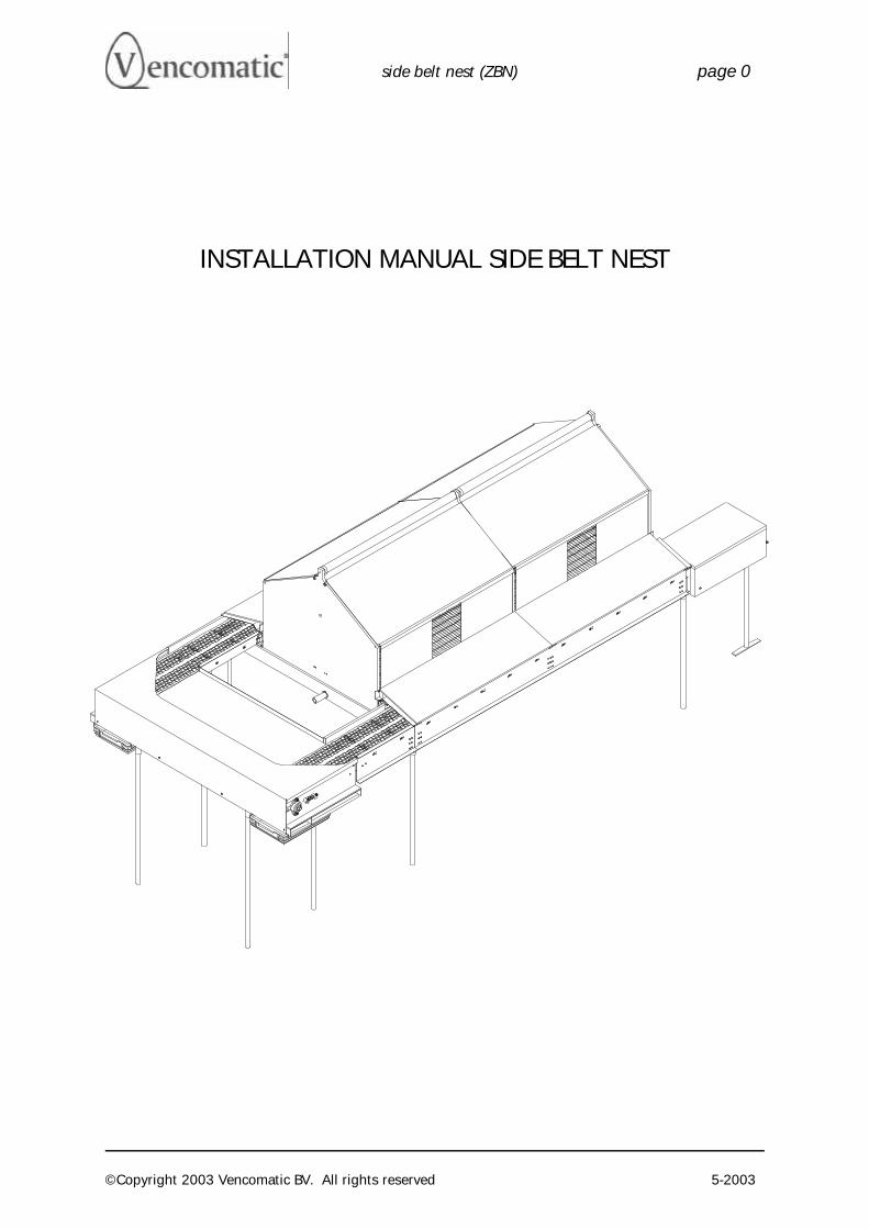
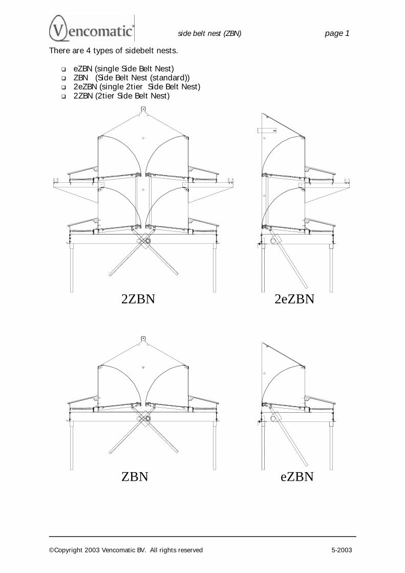
There are 4 types of sidebelt nests.
q eZBN (single Side Belt Nest) q ZBN (Side Belt Nest (standard)) q 2eZBN (single 2tier Side Belt Nest) q 2ZBN (2tier Side Belt Nest)
2ZBN 2eZBN
ZBN eZBN
side belt nest (ZBN) page 2
©Copyright 2003 Vencomatic BV. All rights reserved 5-2003
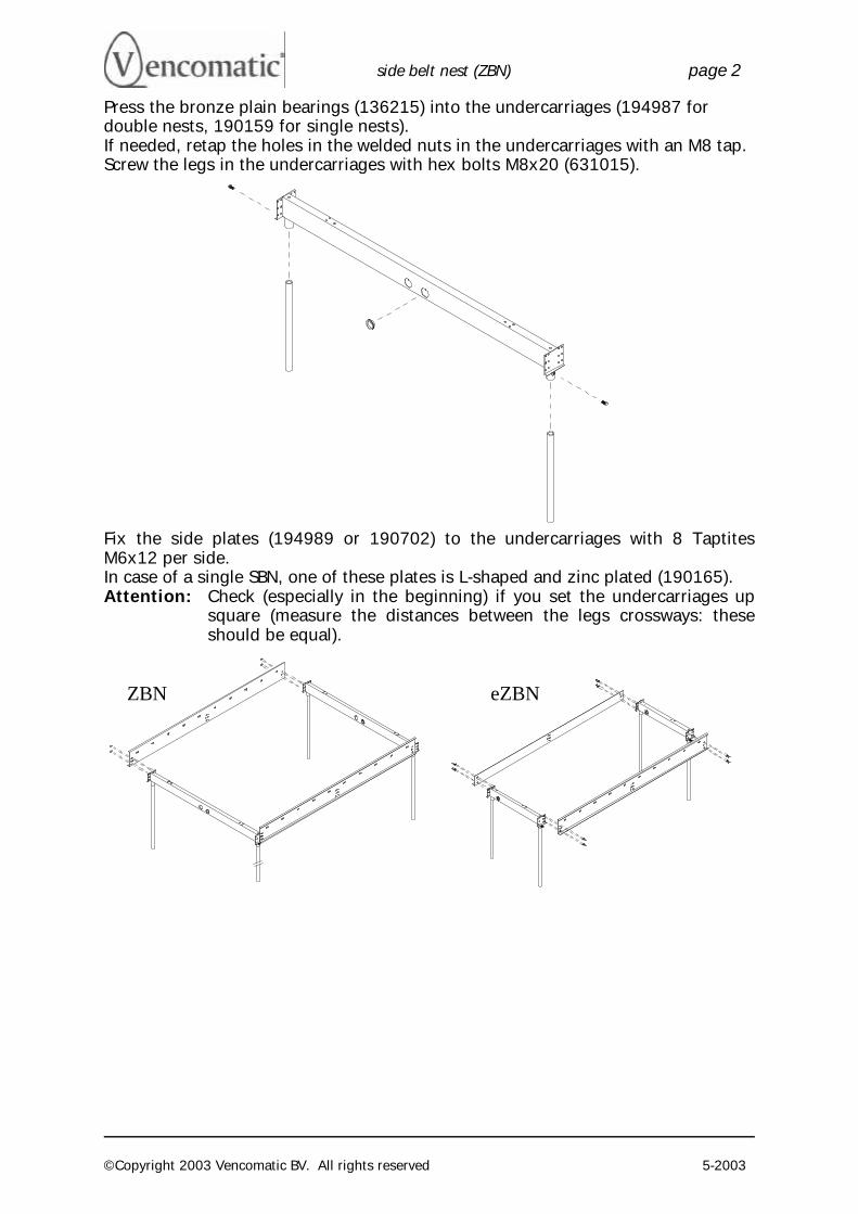
Press the bronze plain bearings (136215) into the undercarriages (194987 for double nests, 190159 for single nests). If needed, retap the holes in the welded nuts in the undercarriages with an M8 tap. Screw the legs in the undercarriages with hex bolts M8x20 (631015).
Fix the side plates (194989 or 190702) to the undercarriages with 8 Taptites M6x12 per side. In case of a single SBN, one of these plates is L-shaped and zinc plated (190165). Attention: Check (especially in the beginning) if you set the undercarriages up
square (measure the distances between the legs crossways: these should be equal).
ZBN eZBN
side belt nest (ZBN) page 3
©Copyright 2003 Vencomatic BV. All rights reserved 5-2003
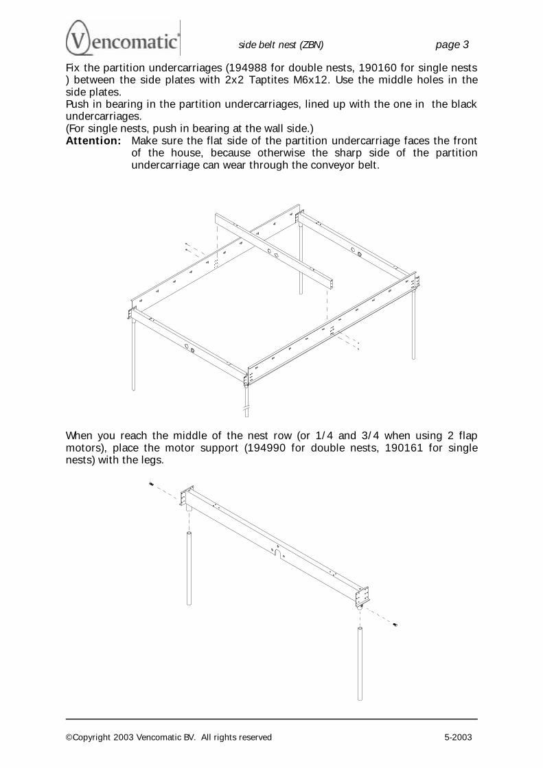
Fix the partition undercarriages (194988 for double nests, 190160 for single nests ) between the side plates with 2x2 Taptites M6x12. Use the middle holes in the side plates. Push in bearing in the partition undercarriages, lined up with the one in the black undercarriages. (For single nests, push in bearing at the wall side.) Attention: Make sure the flat side of the partition undercarriage faces the front
of the house, because otherwise the sharp side of the partition undercarriage can wear through the conveyor belt.
When you reach the middle of the nest row (or 1/4 and 3/4 when using 2 flap motors), place the motor support (194990 for double nests, 190161 for single nests) with the legs.
side belt nest (ZBN) page 4
©Copyright 2003 Vencomatic BV. All rights reserved 5-2003
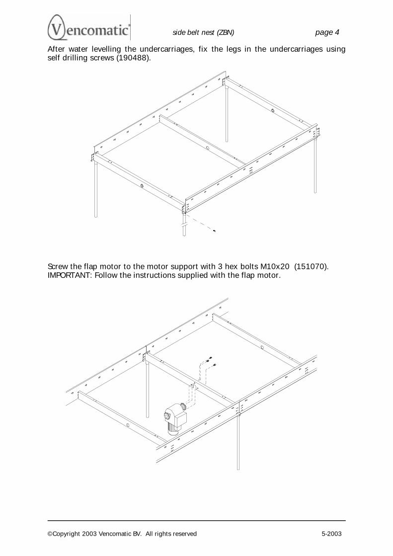
After water levelling the undercarriages, fix the legs in the undercarriages using self drilling screws (190488).
Screw the flap motor to the motor support with 3 hex bolts M10x20 (151070). IMPORTANT: Follow the instructions supplied with the flap motor.
side belt nest (ZBN) page 5
©Copyright 2003 Vencomatic BV. All rights reserved 5-2003
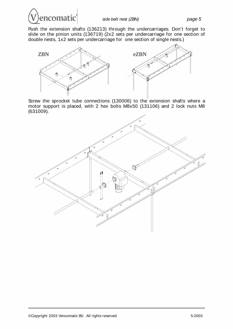
Push the extension shafts (136213) through the undercarriages. Don’t forget to slide on the pinion units (136719) (2x2 sets per undercarriage for one section of double nests, 1x2 sets per undercarriage for one section of single nests.)
Screw the sprocket tube connections (130006) to the extension shafts where a motor support is placed, with 2 hex bolts M8x50 (131106) and 2 lock nuts M8 (631009).
ZBN eZBN
side belt nest (ZBN) page 6
©Copyright 2003 Vencomatic BV. All rights reserved 5-2003
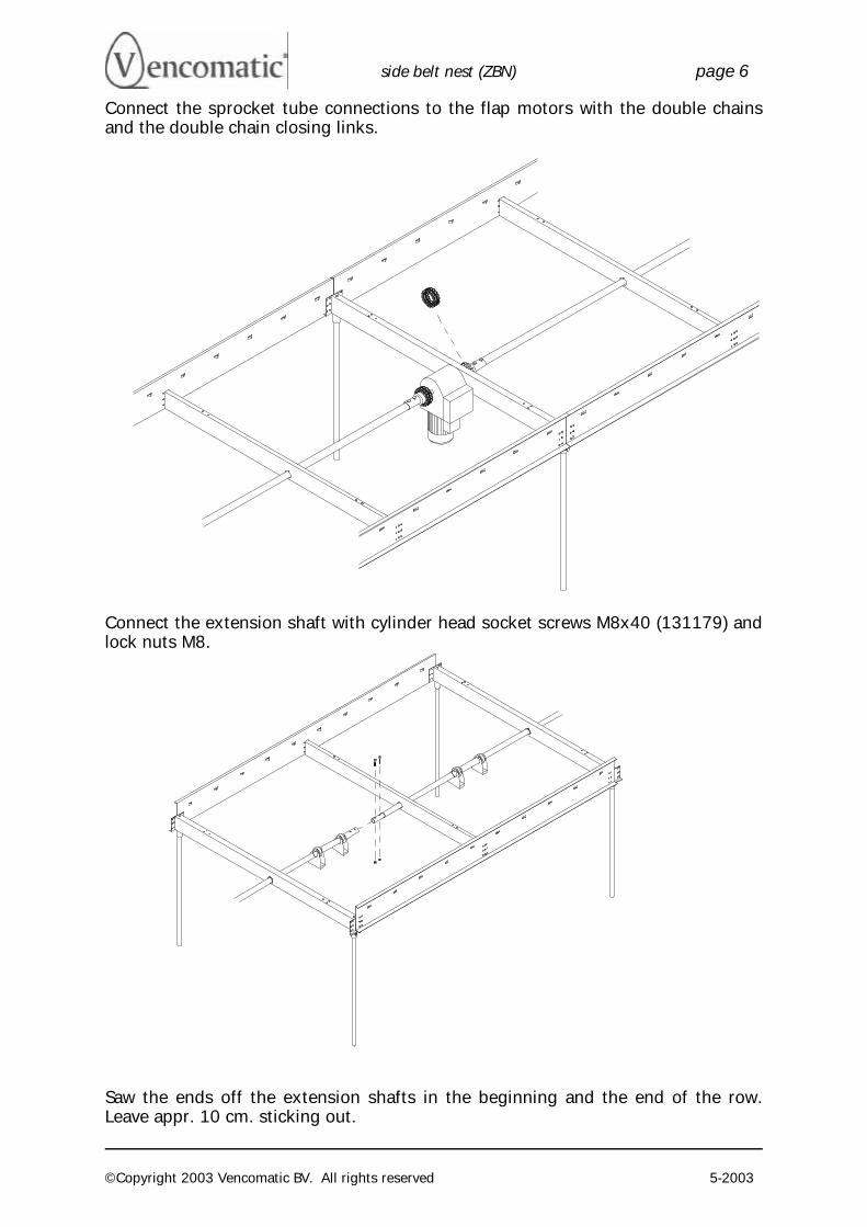
Connect the sprocket tube connections to the flap motors with the double chains and the double chain closing links.
Connect the extension shaft with cylinder head socket screws M8x40 (131179) and lock nuts M8.
Saw the ends off the extension shafts in the beginning and the end of the row. Leave appr. 10 cm. sticking out.
side belt nest (ZBN) page 7
©Copyright 2003 Vencomatic BV. All rights reserved 5-2003
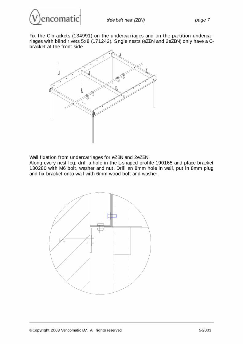
Fix the C-brackets (134991) on the undercarriages and on the partition undercar-riages with blind rivets 5x8 (171242). Single nests (eZBN and 2eZBN) only have a C-bracket at the front side.
Wall fixation from undercarriages for eZBN and 2eZBN: Along every nest leg, drill a hole in the L-shaped profile 190165 and place bracket 130280 with M6 bolt, washer and nut. Drill an 8mm hole in wall, put in 8mm plug and fix bracket onto wall with 6mm wood bolt and washer.
side belt nest (ZBN) page 8
©Copyright 2003 Vencomatic BV. All rights reserved 5-2003
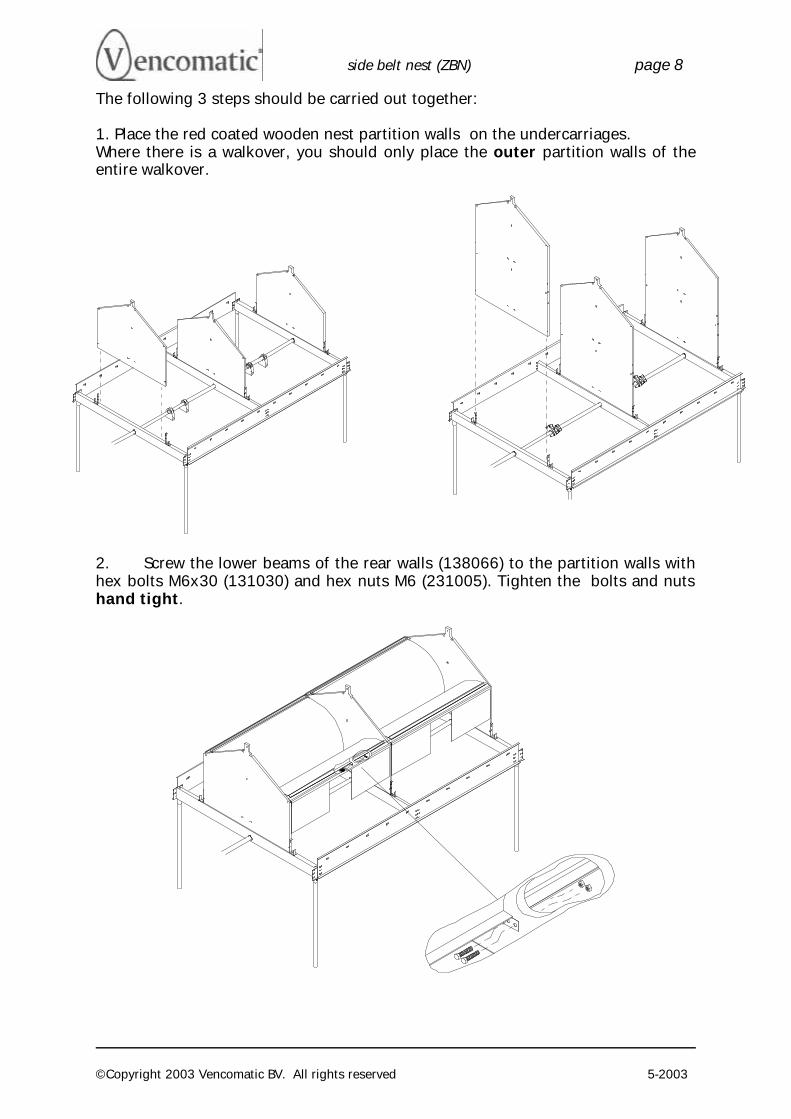
The following 3 steps should be carried out together: 1. Place the red coated wooden nest partition walls on the undercarriages. Where there is a walkover, you should only place the outer partition walls of the entire walkover.
2. Screw the lower beams of the rear walls (138066) to the partition walls with hex bolts M6x30 (131030) and hex nuts M6 (231005). Tighten the bolts and nuts hand tight.
side belt nest (ZBN) page 9
©Copyright 2003 Vencomatic BV. All rights reserved 5-2003
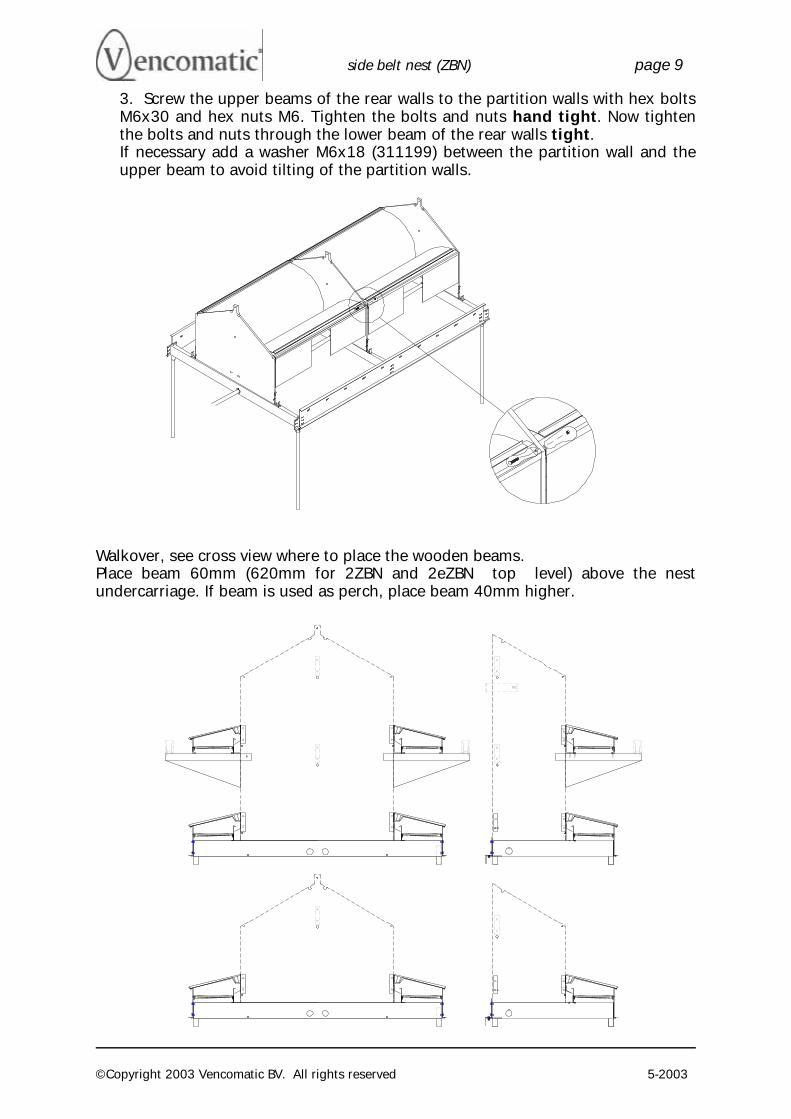
3. Screw the upper beams of the rear walls to the partition walls with hex bolts M6x30 and hex nuts M6. Tighten the bolts and nuts hand tight. Now tighten the bolts and nuts through the lower beam of the rear walls tight. If necessary add a washer M6x18 (311199) between the partition wall and the upper beam to avoid tilting of the partition walls.
Walkover, see cross view where to place the wooden beams. Place beam 60mm (620mm for 2ZBN and 2eZBN top level) above the nest undercarriage. If beam is used as perch, place beam 40mm higher.
side belt nest (ZBN) page 10
©Copyright 2003 Vencomatic BV. All rights reserved 5-2003
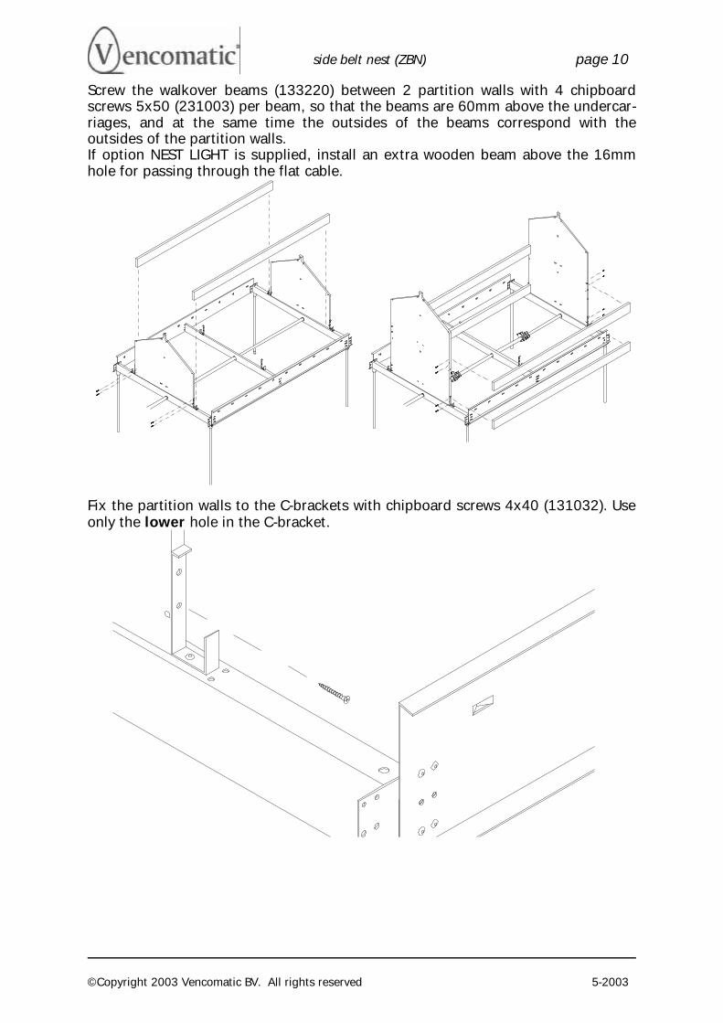
Screw the walkover beams (133220) between 2 partition walls with 4 chipboard screws 5x50 (231003) per beam, so that the beams are 60mm above the undercar-riages, and at the same time the outsides of the beams correspond with the outsides of the partition walls. If option NEST LIGHT is supplied, install an extra wooden beam above the 16mm hole for passing through the flat cable.
Fix the partition walls to the C-brackets with chipboard screws 4x40 (131032). Use only the lower hole in the C-bracket.
side belt nest (ZBN) page 11
©Copyright 2003 Vencomatic BV. All rights reserved 5-2003
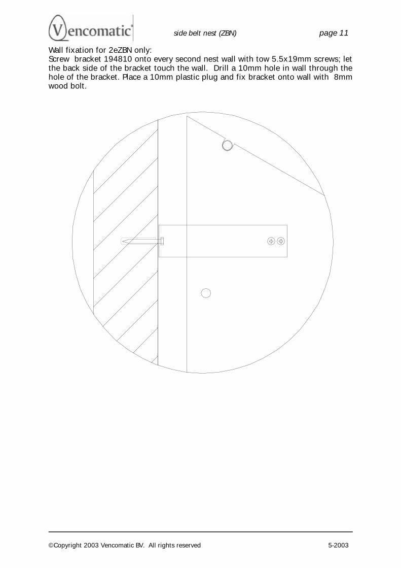
Wall fixation for 2eZBN only: Screw bracket 194810 onto every second nest wall with tow 5.5x19mm screws; let the back side of the bracket touch the wall. Drill a 10mm hole in wall through the hole of the bracket. Place a 10mm plastic plug and fix bracket onto wall with 8mm wood bolt.
side belt nest (ZBN) page 12
©Copyright 2003 Vencomatic BV. All rights reserved 5-2003
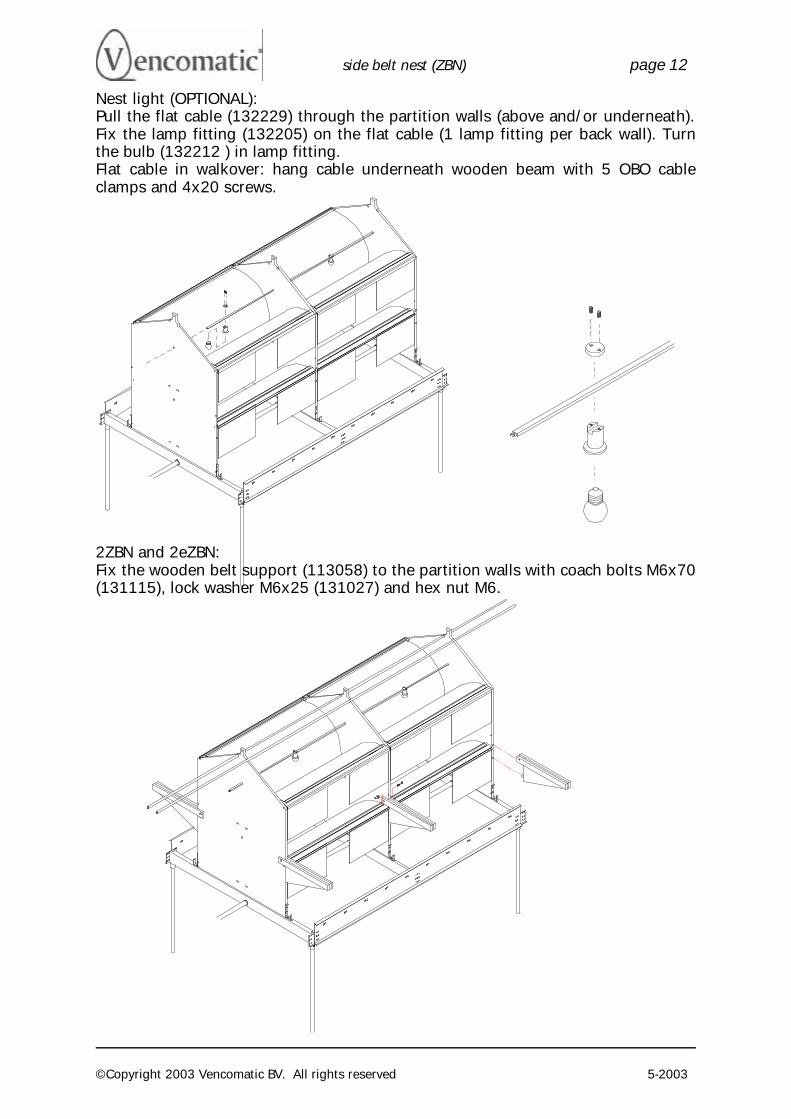
Nest light (OPTIONAL): Pull the flat cable (132229) through the partition walls (above and/or underneath). Fix the lamp fitting (132205) on the flat cable (1 lamp fitting per back wall). Turn the bulb (132212 ) in lamp fitting. Flat cable in walkover: hang cable underneath wooden beam with 5 OBO cable clamps and 4x20 screws.
2ZBN and 2eZBN: Fix the wooden belt support (113058) to the partition walls with coach bolts M6x70 (131115), lock washer M6x25 (131027) and hex nut M6.
side belt nest (ZBN) page 13
©Copyright 2003 Vencomatic BV. All rights reserved 5-2003
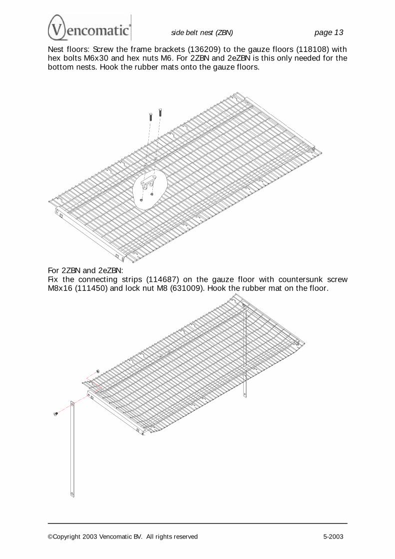
Nest floors: Screw the frame brackets (136209) to the gauze floors (118108) with hex bolts M6x30 and hex nuts M6. For 2ZBN and 2eZBN is this only needed for the bottom nests. Hook the rubber mats onto the gauze floors.
For 2ZBN and 2eZBN: Fix the connecting strips (114687) on the gauze floor with countersunk screw M8x16 (111450) and lock nut M8 (631009). Hook the rubber mat on the floor.
side belt nest (ZBN) page 14
©Copyright 2003 Vencomatic BV. All rights reserved 5-2003
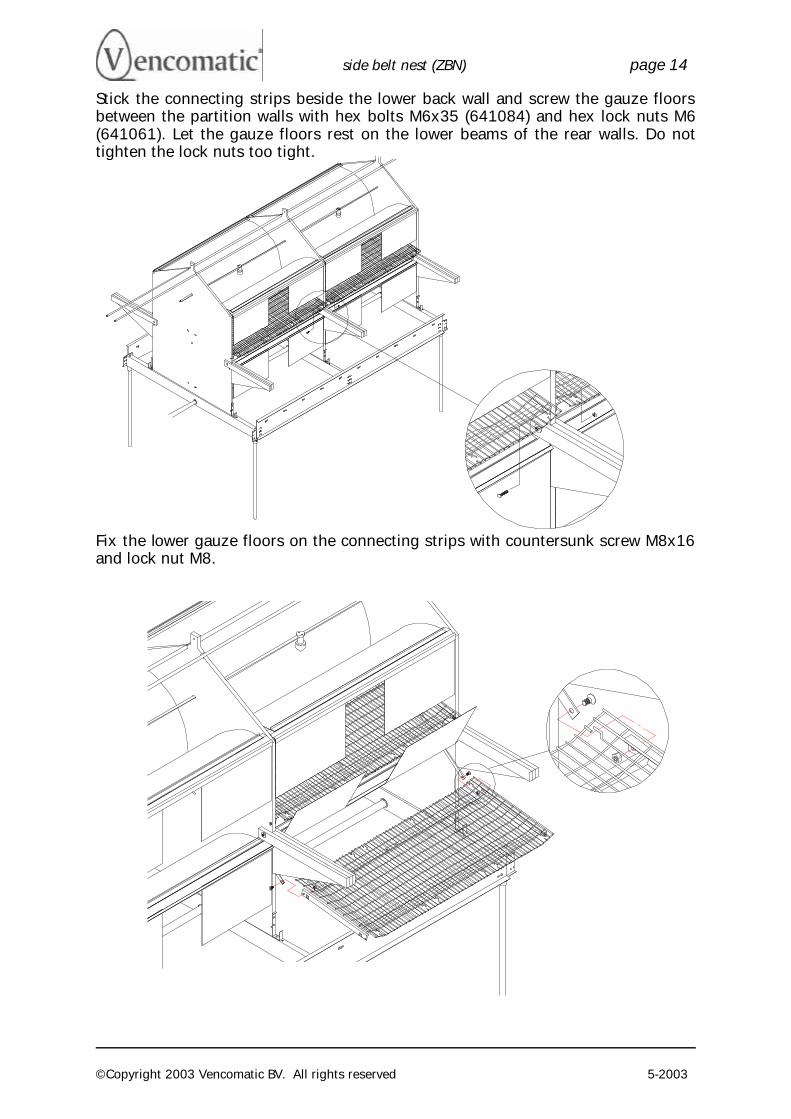
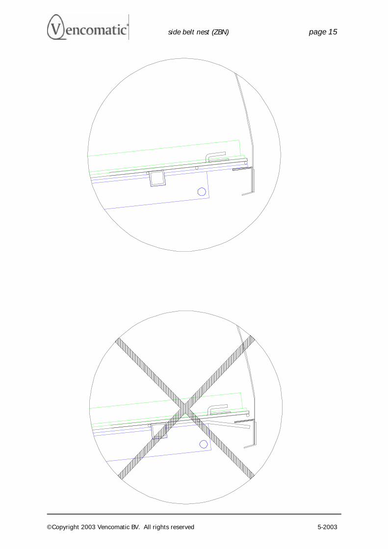
Stick the connecting strips beside the lower back wall and screw the gauze floors between the partition walls with hex bolts M6x35 (641084) and hex lock nuts M6 (641061). Let the gauze floors rest on the lower beams of the rear walls. Do not tighten the lock nuts too tight.
Fix the lower gauze floors on the connecting strips with countersunk screw M8x16 and lock nut M8.
side belt nest (ZBN) page 15
©Copyright 2003 Vencomatic BV. All rights reserved 5-2003
side belt nest (ZBN) page 16
©Copyright 2003 Vencomatic BV. All rights reserved 5-2003
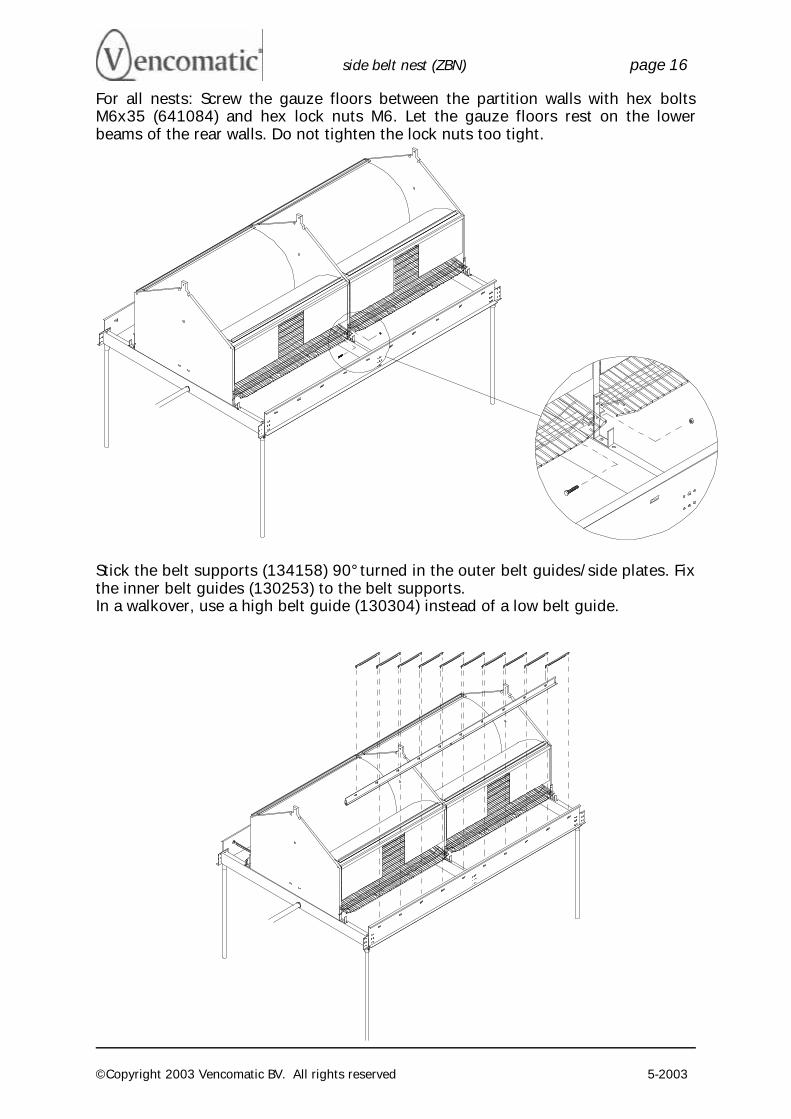
For all nests: Screw the gauze floors between the partition walls with hex bolts M6x35 (641084) and hex lock nuts M6. Let the gauze floors rest on the lower beams of the rear walls. Do not tighten the lock nuts too tight.
Stick the belt supports (134158) 90° turned in the outer belt guides/side plates. Fix the inner belt guides (130253) to the belt supports. In a walkover, use a high belt guide (130304) instead of a low belt guide.
side belt nest (ZBN) page 17
©Copyright 2003 Vencomatic BV. All rights reserved 5-2003
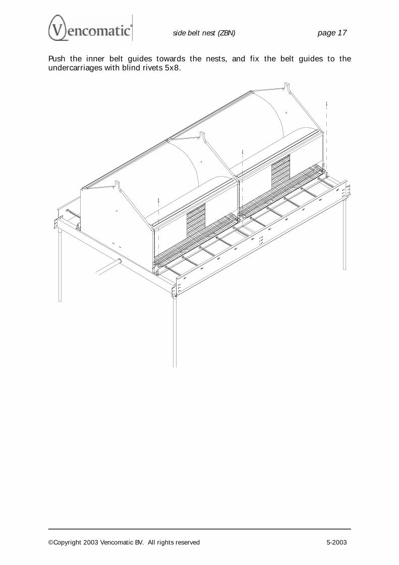
Push the inner belt guides towards the nests, and fix the belt guides to the undercarriages with blind rivets 5x8.
side belt nest (ZBN) page 18
©Copyright 2003 Vencomatic BV. All rights reserved 5-2003
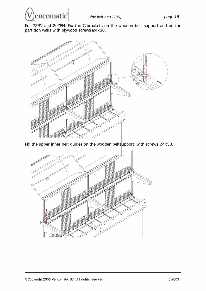
For 2ZBN and 2eZBN: Fix the C-brackets on the wooden belt support and on the partition walls with plywood screws Ø4x30.
Fix the upper inner belt guides on the wooden beltsupport with screws Ø4x30.
side belt nest (ZBN) page 19
©Copyright 2003 Vencomatic BV. All rights reserved 5-2003
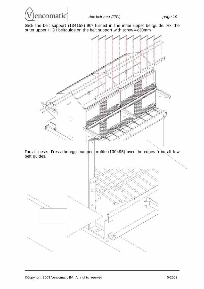
Stick the belt support (134158) 90º turned in the inner upper beltguide. Fix the outer upper HIGH beltguide on the belt support with screw 4x30mm
For all nests: Press the egg bumper profile (130495) over the edges from all low belt guides.

side belt nest (ZBN) page 20
©Copyright 2003 Vencomatic BV. All rights reserved 5-2003
Egg belt return station: From the final nest undercarriage; cut off the mounting flange which is not used for the side plates of the nest undercarriages. Now you can fix the return station to the final undercarriage with bracket 130357
side belt nest (ZBN) page 21
©Copyright 2003 Vencomatic BV. All rights reserved 5-2003
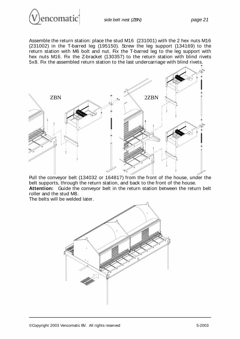
Assemble the return station: place the stud M16 (231001) with the 2 hex nuts M16 (231002) in the T-barred leg (195150). Screw the leg support (134169) to the return station with M6 bolt and nut. Fix the T-barred leg to the leg support with hex nuts M16. Fix the Z-bracket (130357) to the return station with blind rivets 5x8. Fix the assembled return station to the last undercarriage with blind rivets.
Pull the conveyor belt (134032 or 164817) from the front of the house, under the belt supports, through the return station, and back to the front of the house. Attention: Guide the conveyor belt in the return station between the return belt roller and the stud M8. The belts will be welded later.
ZBN 2ZBN
side belt nest (ZBN) page 22
©Copyright 2003 Vencomatic BV. All rights reserved 5-2003
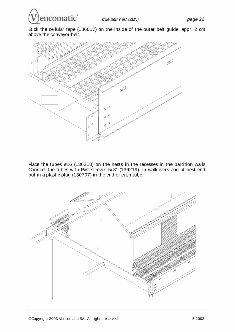
Stick the cellular tape (136017) on the inside of the outer belt guide, appr. 2 cm. above the conveyor belt.
Place the tubes ø16 (136218) on the nests in the recesses in the partition walls. Connect the tubes with PVC sleeves 5/8" (136219). In walkovers and at nest end, put in a plastic plug (130707) in the end of each tube.
side belt nest (ZBN) page 23
©Copyright 2003 Vencomatic BV. All rights reserved 5-2003
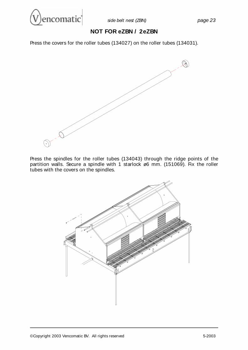
NOT FOR eZBN / 2eZBN Press the covers for the roller tubes (134027) on the roller tubes (134031).
Press the spindles for the roller tubes (134043) through the ridge points of the partition walls. Secure a spindle with 1 starlock ø6 mm. (151069). Fix the roller tubes with the covers on the spindles.
side belt nest (ZBN) page 24
©Copyright 2003 Vencomatic BV. All rights reserved 5-2003
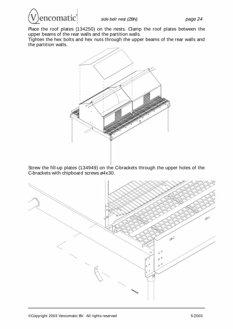
Place the roof plates (134250) on the nests. Clamp the roof plates between the upper beams of the rear walls and the partition walls. Tighten the hex bolts and hex nuts through the upper beams of the rear walls and the partition walls.
Screw the fill-up plates (134949) on the C-brackets through the upper holes of the C-brackets with chipboard screws ø4x30.
side belt nest (ZBN) page 25
©Copyright 2003 Vencomatic BV. All rights reserved 5-2003
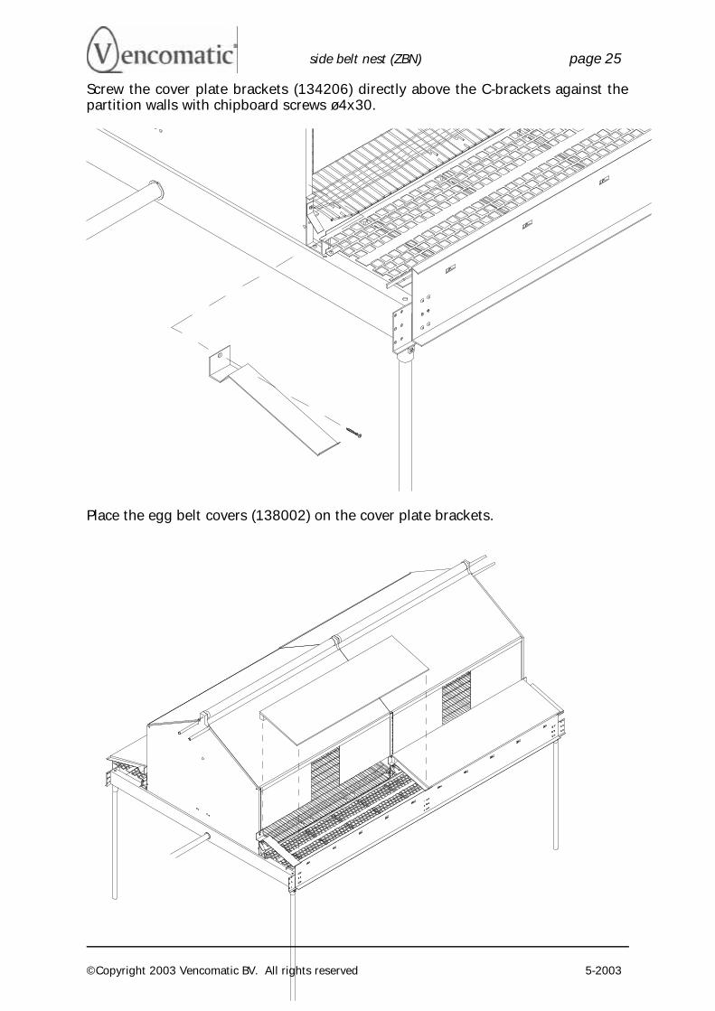
Screw the cover plate brackets (134206) directly above the C-brackets against the partition walls with chipboard screws ø4x30.
Place the egg belt covers (138002) on the cover plate brackets.
side belt nest (ZBN) page 26
©Copyright 2003 Vencomatic BV. All rights reserved 5-2003
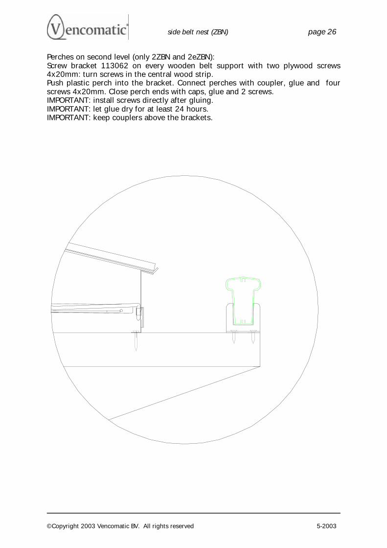
Perches on second level (only 2ZBN and 2eZBN): Screw bracket 113062 on every wooden belt support with two plywood screws 4x20mm: turn screws in the central wood strip. Push plastic perch into the bracket. Connect perches with coupler, glue and four screws 4x20mm. Close perch ends with caps, glue and 2 screws. IMPORTANT: install screws directly after gluing. IMPORTANT: let glue dry for at least 24 hours. IMPORTANT: keep couplers above the brackets.
side belt nest (ZBN) page 27
©Copyright 2003 Vencomatic BV. All rights reserved 5-2003
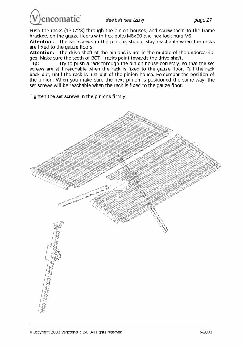
Push the racks (130723) through the pinion houses, and screw them to the frame brackets on the gauze floors with hex bolts M6x50 and hex lock nuts M6. Attention: The set screws in the pinions should stay reachable when the racks are fixed to the gauze floors. Attention: The drive shaft of the pinions is not in the middle of the undercarria-ges. Make sure the teeth of BOTH racks point towards the drive shaft. Tip: Try to push a rack through the pinion house correctly, so that the set screws are still reachable when the rack is fixed to the gauze floor. Pull the rack back out, until the rack is just out of the pinion house. Remember the position of the pinion. When you make sure the next pinion is positioned the same way, the set screws will be reachable when the rack is fixed to the gauze floor. Tighten the set screws in the pinions firmly!
side belt nest (ZBN) page 28
©Copyright 2003 Vencomatic BV. All rights reserved 5-2003
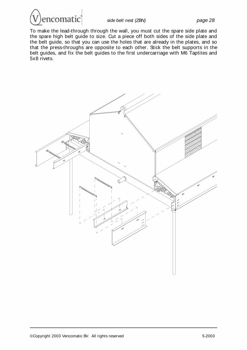
To make the lead-through through the wall, you must cut the spare side plate and the spare high belt guide to size. Cut a piece off both sides of the side plate and the belt guide, so that you can use the holes that are already in the plates, and so that the press-throughs are opposite to each other. Stick the belt supports in the belt guides, and fix the belt guides to the first undercarriage with M6 Taptites and 5x8 rivets.
side belt nest (ZBN) page 29
©Copyright 2003 Vencomatic BV. All rights reserved 5-2003
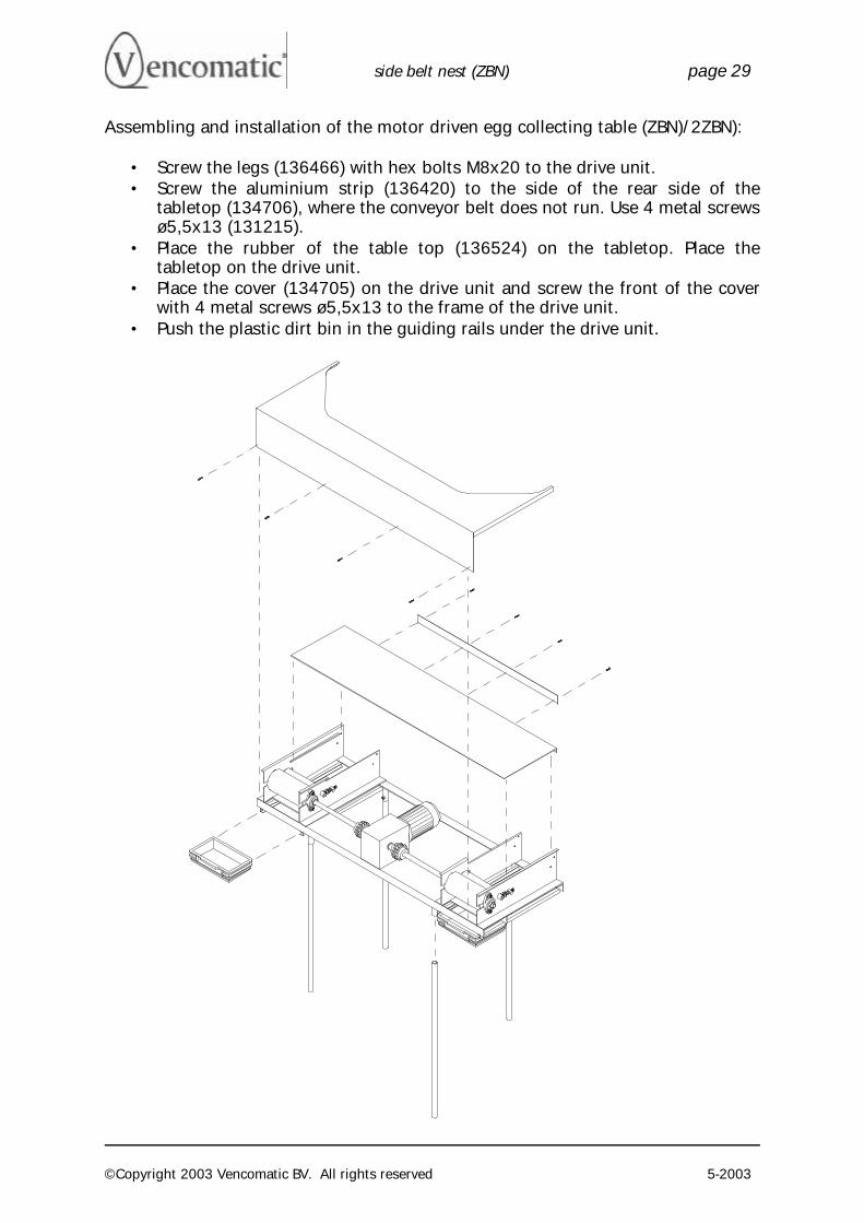
Assembling and installation of the motor driven egg collecting table (ZBN)/2ZBN):
• Screw the legs (136466) with hex bolts M8x20 to the drive unit. • Screw the aluminium strip (136420) to the side of the rear side of the
tabletop (134706), where the conveyor belt does not run. Use 4 metal screws ø5,5x13 (131215).
• Place the rubber of the table top (136524) on the tabletop. Place the tabletop on the drive unit.
• Place the cover (134705) on the drive unit and screw the front of the cover with 4 metal screws ø5,5x13 to the frame of the drive unit.
• Push the plastic dirt bin in the guiding rails under the drive unit.
side belt nest (ZBN) page 30
©Copyright 2003 Vencomatic BV. All rights reserved 5-2003
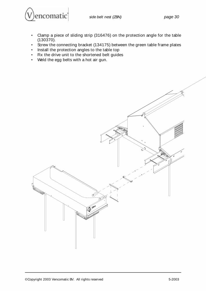
• Clamp a piece of sliding strip (316476) on the protection angle for the table (130370).
• Screw the connecting bracket (134175) between the green table frame plates • Install the protection angles to the table top • Fix the drive unit to the shortened belt guides • Weld the egg belts with a hot air gun.
side belt nest (ZBN) page 31
©Copyright 2003 Vencomatic BV. All rights reserved 5-2003
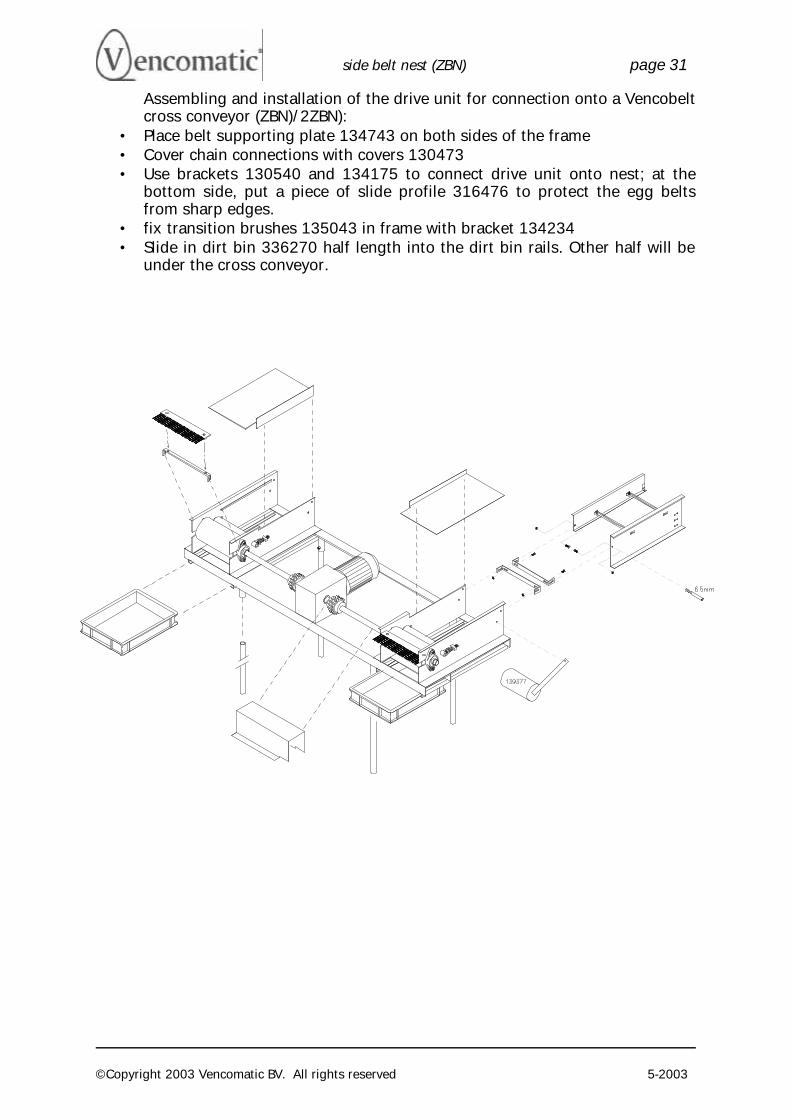
Assembling and installation of the drive unit for connection onto a Vencobelt cross conveyor (ZBN)/2ZBN):
• Place belt supporting plate 134743 on both sides of the frame • Cover chain connections with covers 130473 • Use brackets 130540 and 134175 to connect drive unit onto nest; at the
bottom side, put a piece of slide profile 316476 to protect the egg belts from sharp edges.
• fix transition brushes 135043 in frame with bracket 134234 • Slide in dirt bin 336270 half length into the dirt bin rails. Other half will be
under the cross conveyor.
side belt nest (ZBN) page 32
©Copyright 2003 Vencomatic BV. All rights reserved 5-2003
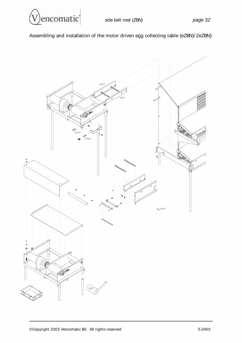
Assembling and installation of the motor driven egg collecting table (eZBN)/2eZBN):
side belt nest (ZBN) page 33
©Copyright 2003 Vencomatic BV. All rights reserved 5-2003
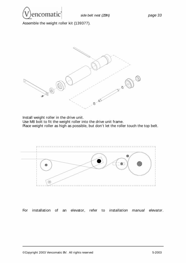
Assemble the weight roller kit (139377).
Install weight roller in the drive unit. Use M8 bolt to fit the weight roller into the drive unit frame. Place weight roller as high as possible, but don’t let the roller touch the top belt.
For installation of an elevator, refer to installation manual elevator.
side belt nest (ZBN) page 34
©Copyright 2003 Vencomatic BV. All rights reserved 5-2003
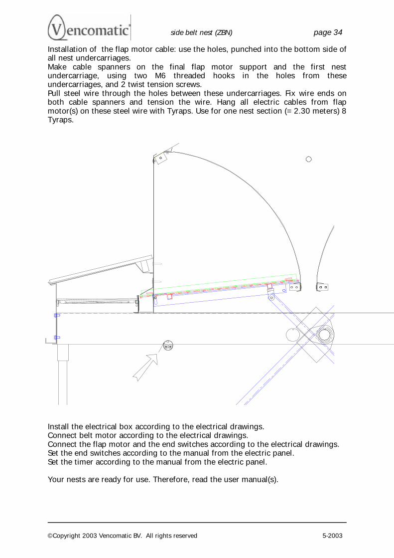
Installation of the flap motor cable: use the holes, punched into the bottom side of all nest undercarriages. Make cable spanners on the final flap motor support and the first nest undercarriage, using two M6 threaded hooks in the holes from these undercarriages, and 2 twist tension screws. Pull steel wire through the holes between these undercarriages. Fix wire ends on both cable spanners and tension the wire. Hang all electric cables from flap motor(s) on these steel wire with Tyraps. Use for one nest section (= 2.30 meters) 8 Tyraps.
Install the electrical box according to the electrical drawings. Connect belt motor according to the electrical drawings. Connect the flap motor and the end switches according to the electrical drawings. Set the end switches according to the manual from the electric panel. Set the timer according to the manual from the electric panel. Your nests are ready for use. Therefore, read the user manual(s).
side belt nest (ZBN) page 35
©Copyright 2003 Vencomatic BV. All rights reserved 5-2003
return stationretourstationUmlenkungstation retour
return stationretourstationUmlenkungstation retour
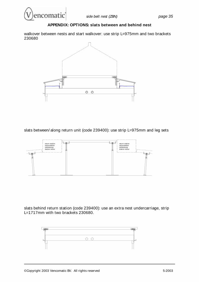
APPENDIX: OPTIONS: slats between and behind nest
walkover between nests and start walkover: use strip L=975mm and two brackets 230680
slats between/along return unit (code 239400): use strip L=975mm and leg sets
slats behind return station (code 239400): use an extra nest undercarriage, strip L=1717mm with two brackets 230680.
side belt nest (ZBN) page 36
©Copyright 2003 Vencomatic BV. All rights reserved 5-2003
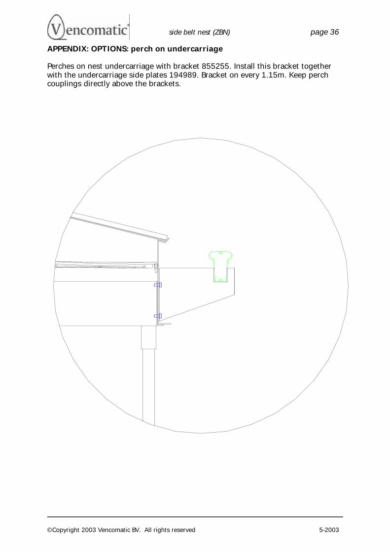
APPENDIX: OPTIONS: perch on undercarriage
Perches on nest undercarriage with bracket 855255. Install this bracket together with the undercarriage side plates 194989. Bracket on every 1.15m. Keep perch couplings directly above the brackets.
side belt nest (ZBN) page 37
©Copyright 2003 Vencomatic BV. All rights reserved 5-2003
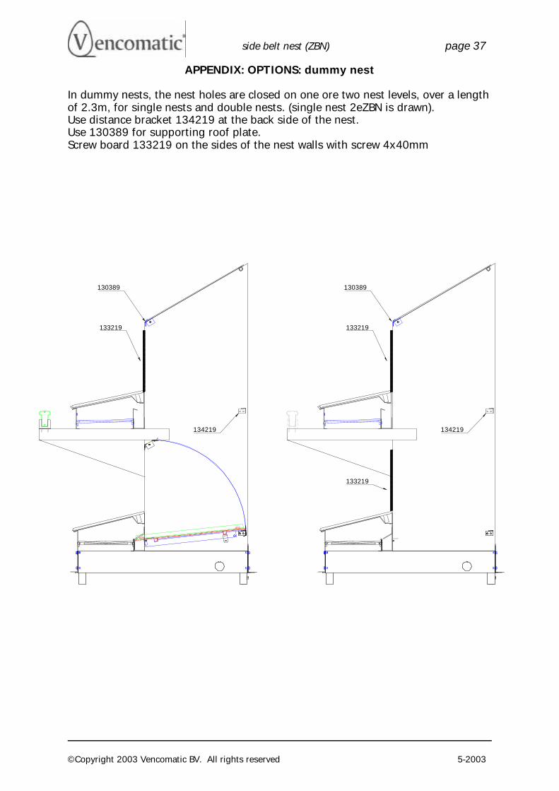
APPENDIX: OPTIONS: dummy nest
In dummy nests, the nest holes are closed on one ore two nest levels, over a length of 2.3m, for single nests and double nests. (single nest 2eZBN is drawn). Use distance bracket 134219 at the back side of the nest. Use 130389 for supporting roof plate. Screw board 133219 on the sides of the nest walls with screw 4x40mm
134219 134219
130389
133219 133219
130389
133219
side belt nest (ZBN) page 38
©Copyright 2003 Vencomatic BV. All rights reserved 5-2003
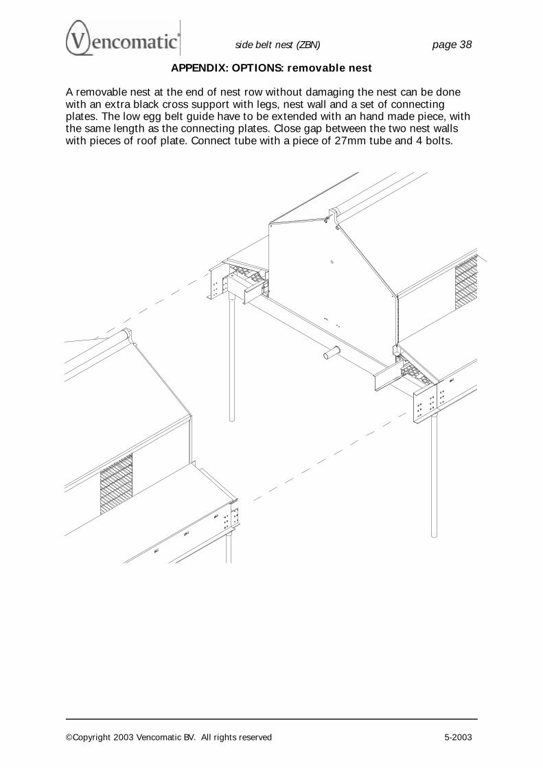
APPENDIX: OPTIONS: removable nest
A removable nest at the end of nest row without damaging the nest can be done with an extra black cross support with legs, nest wall and a set of connecting plates. The low egg belt guide have to be extended with an hand made piece, with the same length as the connecting plates. Close gap between the two nest walls with pieces of roof plate. Connect tube with a piece of 27mm tube and 4 bolts.
side belt nest (ZBN) page 39
©Copyright 2003 Vencomatic BV. All rights reserved 5-2003
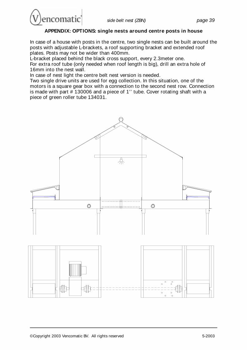
APPENDIX: OPTIONS: single nests around centre posts in house
In case of a house with posts in the centre, two single nests can be built around the posts with adjustable L-brackets, a roof supporting bracket and extended roof plates. Posts may not be wider than 400mm. L-bracket placed behind the black cross support, every 2.3meter one. For extra roof tube (only needed when roof length is big), drill an extra hole of 16mm into the nest wall. In case of nest light the centre belt nest version is needed. Two single drive units are used for egg collection. In this situation, one of the motors is a square gear box with a connection to the second nest row. Connection is made with part # 130006 and a piece of 1’’ tube. Cover rotating shaft with a piece of green roller tube 134031.