Embed Size (px)
Citation preview

www.furuno.comAll brand and product names are trademarks, registered trademarks or service marks of their respective holders.
Installation ManualRADAR SENSOR
MODEL DRS6A-NXT/DRS12A-NXTDRS25A-NXT
(Product Name: SOLID STATE DOPPLER RADAR)
SAFETY INSTRUCTIONS ................................................................................................ iSYSTEM CONFIGURATION .......................................................................................... iiiINSTALLATION SPECIFICATIONS............................................................................... ivFOREWORD.................................................................................................................... vEQUIPMENT LISTS........................................................................................................ vi
1. INSTALLATION AND WIRING................................................................................... 11.1 Mounting Considerations ......................................................................................................11.2 Included Items.......................................................................................................................41.3 Required Tools and Materials ...............................................................................................51.4 Fastening the Radiator to the Radiator Bracket....................................................................61.5 Mounting the Antenna Unit ...................................................................................................81.6 Wiring..................................................................................................................................11
2. INITIAL SETUP......................................................................................................... 152.1 Initial Setup for TZT9/TZT14/TZTBB ..................................................................................162.2 Initial Setup for TZTL12F/TZTL15F/TZT2BB/TZT12F/TZT16F/TZT19F.............................18
3. MAINTENANCE, TROUBLE SHOOTING................................................................ 213.1 Maintenance .......................................................................................................................223.2 Troubleshooting ..................................................................................................................233.3 Replacement of Fuse..........................................................................................................233.4 Life of Parts.........................................................................................................................24
APPENDIX 1 RADIO REGULATORY INFORMATION ............................................AP-1SPECIFICATIONS ..................................................................................................... SP-1PACKING LISTS ......................................................................................................... A-1OUTLINE DRAWINGS ................................................................................................ D-1INTERCONNECTION DIAGRAM ................................................................................ S-1

SAFETY INSTRUCTIONS
Mandatory Action Prohibitive ActionWarning, Caution
WARNING
The installer of the equipment must read the safety instructions before attempting toinstall the equipment.
Indicates a potentially hazardous situation which,if not avoided, can result in death or serious injury.
Indicates a potentially hazardous situation which, if not avoided, can result in minor or moderate injury.
WARNING
Turn off the power at the switchboard before beginning the installation.Fire or electrical shock can result if the power is left on.
Do not open the equipment unless you are well familiar with electrical circuits.Only qualified personnel should work inside the equipment.
Be sure that the power supply is compatible with the voltage rating of the equipment.Connection of an incorrect power supply can cause fire or damage the equipment.
Use only the specified power and signal cable.Fire or damage to the equipment can result if a different cable is used.
Wear a safety belt and hard hat when working on the antenna unit.Serious injury or death can result if someone falls from the radar mast.
Do not disassemble or modify the equipment.Fire, electrical shock or serious injury can result.
Construct a suitable service platform from which to install the antenna unit.Serious injury or death can result if someone falls from the radar mast.
Keep the objects away from the antenna unit, so as not to impede rotation of the antenna.Fire, electrical shock or serious injury can result.
Use the proper fuse.Use of a wrong fuse can damage the equipment or cause fire.
Do not depend one navigation device for the navigation of the vessel.For the safety of vessel and crew, the navigator must check all aids available to confirm position.
CAUTIONWARNING
i

SAFETY INSTRUCTIONS
Ground the equipment to prevent mutual interference.
WARNING LABELA warning label is attached to the antenna unit. Do not remove the label.If the label is missing or damaged, contact your dealer about replacement.
Name: Warning Label (2)Type: 03-129-1001-3Code No: 100-236-743
It is recommended that you connect the antenna unit to a disconnecting device (circuit breaker, etc.) to control the power.
CAUTION
Observe the following compass safe distances to prevent deviation of a magnetic compass:
0.70 m 0.40 m
Standard compass
Steering compass
Importer in Europe
The following concern acts as our importer in Europe, as defined in DECISION No 768/2008/EC.- Name: FURUNO EUROPE B.V.- Address: Ridderhaven 19B, 2984 BT Ridderkerk, The Netherlands
Program No.
• 0359423-01.** ** denotes minor modifications.
The radar antenna emits electromagnetic radio frequency (RF) energy which can be harmful, particularly to your eyes. Never look directly into the antenna aperture from a close distance while the radar is in operation or expose yourself to the transmitting antenna at a close distance.Distances at which RF radiation levels of 100, 50 and 10 W/m2 exist are given in the table below.
WARNING
N/AXN10A 0.7 mN/A100 W/m2 50 W/m2 10 W/m2Radiator
XN12AXN13A
N/A 0.6 mN/AN/A 0.4 mN/A
CE declarations
With regard to CE declarations, please refer to our website (www.furuno.com), for further information about RoHS conformity declarations.
Do not use high-pressure cleaners to clean this equipment.
This equipment has the waterproof rating outlined in the specifications, at the back of this manual. However, the use of high-pressure cleaning equipment can cause water ingress, resulting in damage to, or failure of, the equipment.
0.70 m 0.40 m0.70 m 0.40 m
Unit
DRS6A-NXTDRS12A-NXTDRS25A-NXT
100 W/m2 50 W/m2 10 W/m2RadiatorXN12AXN13A
0.2 m 1.9 m0.5 m0.15 m 1.8 m0.4 m
DRS6A-NXT
DRS12A-NXT
100 W/m2 50 W/m2 10 W/m2RadiatorXN12AXN13A
0.3 m 2.8 m0.47 m0.2 m 2.65 m0.3 m
DRS25A-NXT
Importer in UK
The following concern acts as our importer in UK, as defined in SI 2016/1025 as amended SI 2019/470.- Name: FURUNO (UK) LTD.- Address: West Building Penner Road Havant Hampshire PO9 1QY, U.K.
ii

SYSTEM CONFIGURATION
This radar series is compatible with the FURUNO Multi Function Displays and software version combinations shown below. The combination with other models or software versions may not op-erate properly.
• TZT9, TZT14 and TZTBB: Version 6.01 or laterTZTL12F, TZTL15F and TZT2BB: Version 6.21 or laterTZT12F, TZT16F and TZT19F: Version 1.05 or later
: Standard supply: Optional or local supply
Antenna UnitRSB-137-119 (DRS6A-NXT)
RSB-137-125 (DRS12A-NXT)RSB-137-126 (DRS25A-NXT)
Multi Function DisplayNavNet TZtouch/NavNet TZtouch2/
NavNet TZtouch3
Multi Function DisplayNavNet TZtouch/NavNet TZtouch2/
NavNet TZtouch3
Ethernet HUBHUB-101
Ship's battery*2
(24 VDC*3 or12 VDC*3)
*1: Radiator XN10A only used with DRS6A-NXT.*2: Radiator XN13A cannot be used with 12 VDC. Connect the antenna unit to the ship's battery via a
switchboard.*3: 12VDC is only used with DRS6A-NXT.
DRS12A-NXT and DRS25A-NXT are 24VDC only.
Power/LAN cable
Cable assembly
RadiatorXN10A (3.4 ft)*1
XN12A (4 ft)XN13A (6 ft)
iii

INSTALLATION SPECIFICATIONS
Note 1: Radiator XN10A is only used with DRS6A-NXT.
Note 2: 12VDC is only used with DRS6A-NXT. DRS12A-NXT and DRS25A-NXT are 24VDC only.
Note 3: DO NOT USE 15 A fuse for 24 VDC. Use of a wrong fuse can damage the equipment or cause fire.
Voltage of Ship’s Main and Usable Radiator
Voltage of Ship’s Main and Usable Cable Length
Voltage of Ship’s Main and Fuse to be used
RadiatorSupply Voltage XN10A XN12A XN13A
12 VDC OK OK Not available24 VDC OK OK OK
Cable LengthSupply Voltage 10 m 15 m 20 m 30 m
12 VDC OK Not available Not available Not available24 VDC OK OK OK OK
Cable LengthSupply Voltage 10 m 15 m 20 m 30 m
12 VDC 15 A Not available Not available Not available24 VDC 10 A 10 A 10 A 10 A
iv

FOREWORD
A Word to the Owner of the DRS6A-NXT/DRS12A-NXT/DRS25A-NXT Marine Radar
Congratulations on your choice of the FURUNO DRS6A-NXT/DRS12A-NXT/DRS25A-NXT Ma-rine Radar. We are confident you will see why the FURUNO name has become synonymous with quality and reliability.
Since 1948, FURUNO Electric Company has enjoyed an enviable reputation for innovative and dependable marine electronics equipment. This dedication to excellence is furthered by our ex-tensive global network of agents and dealers.
Your equipment is designed and constructed to meet the rigorous demands of the marine envi-ronment. However, no machine can perform its intended function unless properly installed and maintained. Please carefully read and follow the operation and maintenance procedures set forth in this manual.
We would appreciate feedback from you, the end-user, about whether we are achieving our pur-poses.
Thank you for considering and purchasing FURUNO equipment.
Features
• TARGET ANALYZER* function displays targets which are moving and getting close to own ship in red, other targets in green and rain clutter in blue. Speed analyzing range is ±50 kn.* Requires a GPS sensor. When you change the setting of [Target Analyzer Mode] to [Rain], rain clutter is displayed.
• AUTO TARGET ACQUIRE function automatically acquires only the targets which are moving and getting close to own ship within the range of 3 NM by Doppler calculation. Automatic Dop-pler function will be activated when there is a target which approaches own ship with a speed of over 3 kn.Note: The judged speed of target is dependent on its vector towards own ship.
• The azimuth resolution can be enhanced to as high as twice with using the RezBoost function.Note 1: RezBoost function reflects the settings of [Antenna Length] which are introduced in page 17 and page 19.
Note 2: Refer to the Operator’s Manual for your Multi Function Display regarding the above newfunctions.
• Instant ON function. This radar sensor does not have a magnetron, therefore preheating of the magnetron is unnecessary.
• Reduced electricity emission means no need to worry about the radiation hazard.
• Magnetron-less radar means no periodic replacement of magnetron or related parts.
• The maximum display range is 72 NM (6A-NXT), 96 NM (12A-NXT/25A-NXT) in the single range mode.
• ARPA (Automatic Radar Plotting Aid) function applicable range is 24 NM at the maximum.
• Dual Range Mode has the following limitations.
• The maximum display range is 12 NM.
• The maximum detection range is reduced a maximum of 20% compared to the single display.
v

vi
EQUIPMENT LISTSStandard supply
Note: Radiator XN10A is only used with DRS6A-NXT.
Optional supply
Name Type Code No. Qty RemarksScanner Unit RSB-137-119 -
1For DRS6A-NXT
RSB-137-125 - For DRS12A-NXTRSB-137-126 - For DRS25A-NXT
Radiator XN10A -1
3.4 ftXN12A - 4 ftXN13A - 6 ft
Installation Materials
CP03-37101 001-426-290 1 For scanner unitCP03-22901 008-523-690 1 For radiator
Spare Parts SP03-19101 000-477-060 1 Fuses (10 A, 15 A and 20 A)
Name Type Code No. RemarksLAN Cable MOD-Z072-020+ 001-167-880-10 2 m
MOD-Z072-050+ 001-167-890-10 5 mMOD-Z072-100+ 001-167-900-10 10 m
Joint Box TL-CAT-012 000-167-140-10 For LAN cable extensionInstallation Materials
CP03-38500 000-035-186 Cable assembly (10 m)CP03-38510 000-035-187 Cable assembly (15 m)CP03-38520 000-035-188 Cable assembly (20 m)CP03-38530 000-035-189 Cable assembly (30 m)
EMC Modifica-tion Kit
OP03-259-1 001-524-010 10 mOP03-259-2 001-524-020 15 mOP03-259-3 001-524-030 20 mOP03-259-4 001-524-040 30 m

1. INSTALLATION AND WIRING
1.1 Mounting ConsiderationsSelect a mounting location, keeping in mind the following points:
• Install the antenna unit on the hardtop, radar arch or on a mast on an appropriate platform.
• Locate the antenna where there is a good all-round view. Where possible, there should be no obstructions to the scanning beam such as superstructure or rigging. Obstructions cause shadow sectors and decrease the overall performance of the radar. The loss of performance can cause false echoes and reduce the quality of the observed images. A mast for instance, with a diameter considerably less than the horizontal beam width of the radiator, will cause only a small shadow sector. However, a horizontal spreader, or cross trees in the same horizontal plane as the antenna unit, would be a much more serious obstruction. You would need to place the antenna unit well above or below it. Be sure there are no metallic objects near the antenna.
• It is rarely possible to place the antenna unit where a completely clear view in all directions is available. After fitting the antenna, determining any shadow sectors, their angle and bearing, and their influence on the radar is recommended.
NOTICEDo not apply paint, anti-corrosive sealant or contact spray to coating or plastic parts of the equipment.
Those items contain organic solvents that can damage coating and plastic parts, especially plastic connectors.
(a) Common mast (b) Radar mast
Vertical beam angle = 22°
1

1. INSTALLATION AND WIRING
• In order to reduce electrical interference, avoid routing the power cable near other electrical equipment on-board. Also, avoid running the cable in parallel with other power cables.
• It is not recommended to install the antenna unit on the hardtop of a cabin. Vibra-tions from the antenna unit will pass through the hardtop and into the cabin.
• Setup the antenna unit position on the FURUNO Multi Function Display after install-ing the unit, referring to chapter 2. If the antenna unit position is not setup correctly, the radar echoes on the display may not be aligned with the actual target’s bearing.
• Select a location that does not allow water to accumulate at the installation location.
• A magnetic compass will be affected if the antenna unit is too close to the compass. Observe the compass safe distances mentioned in the SAFETY INSTRUCTIONS to prevent interference to a magnetic compass.
• To ensure proper emission of radar waves, do not paint the radiator.
• Referring to the outline drawings at the back of this manual, allow space for main-tenance and service.
• When this antenna unit is to be installed on a large vessel, consider the following points:
• The supplied cable assembly runs between the antenna unit and display (or eth-ernet HUB) and comes in lengths of 10 m, 15 m, 20 m or 30 m. Select the appro-priate length when purchasing.
• Deposits and fumes from a funnel or other exhaust vent can adversely affect the aerial performance and hot gases may distort the antenna unit. The antenna unit must not be mounted where the temperature is more than 55°C (131°F).
Not recommended
2

1. INSTALLATION AND WIRING
Consideration for selecting a location for installation (multiple radars)
• In case multiple radars are installed on a ship, DO NOT install the DRS6A-NXT/DRS12A-NXT/DRS25A-NXT within the range of the beam area emitted from other radar(s). Use the illustration below for reference when selecting a suitable location for installation. The Solid State Device (SSD) inside the DRS6A-NXT/DRS12A-NXT/DRS25A-NXT will be damaged if it is within the radar beam emission area from other radars.
Installation with the radiotelephone equipment
• Install the open antenna away from radio communication antennas (SSB, VHF, In-marsat) and GPS antennas to prevent radar interference.
• Install the open antenna away from the radiotelephone equipment so that electrical noise does not affect the radiotelephone equipment.
Cable routing
• In order to reduce the chance of picking up electrical interference, avoid, where pos-sible, routing the power/LAN cable and cable assembly near other electrical equip-ment on-board. Also, avoid running the cable in parallel with other electrical cables.
• Make sure that the power/LAN cable does not run horizontally with the cable as-sembly and it is placed away from the cables carrying radio signal and antennas.
For large vessels
• When this radar sensor is to be installed on a large vessel, consider the following points:
• The length of the pre-attached power/LAN cable is 1 m from the open antenna to the connector.
• Deposits and fumes from a funnel or other exhaust vent can adversely affect the aerial performance and hot gases may distort the radiator portion. The radar sen-sor must not be mounted where the temperature is more than 55°C (131°F).
More than 20°
More than 1 m
Other radarMore than 20°
More than 20°More than 20°
Suitable location for installing the DRS6A-NXT/DRS12A-NXT/DRS25A-NXT
Locate the radar out of the radar beam (dark gray) of other radar.
3

1. INSTALLATION AND WIRING
1.2 Included Items
• Radiator* (1 pc):3.4 ft, 4 ft or 6 ft
• Scanner Unit (1 pc)
Radiator
• O-ring (1 pc)
• Flat washer (M8, 4 pcs) • Spring washer (M8, 4 pcs)
• Hex. bolt (M8×30, 4 pcs)
• Adhesive (1 pc)
Scanner Unit
• Stud bolt (M12×70, 4 pcs)
• Flat washer (M12, 4 pcs) • Spring washer (M12, 4 pcs)
• Hex nut (M12, 8 pcs) • Insulation sheet(4 pcs)
• Fuses (3 pcs)
10 A: Used in most cases.15 A: Only for 10 m cable with 12 VDC.20 A: Not used.
• Documents (1 set)
Cable assembly• Cable assembly* (1 pc): 10 m, 15 m, 20 m or 30 m
*: Select the appropriate length when purchasing.
15A
• Fuses 10 A: Used in most cases. 15 A: Only for 10 m cable with 12 VDC. 20 A: Not used.
• Labels 10 A: Used in most cases. 15 A: Only for 10 m cable with 12 VDC. 20 A: Not used.
• DocumentHow to Replace the Fuse (1 pc)
20A
10A
4

1. INSTALLATION AND WIRING
1.3 Required Tools and MaterialsThe following tools should be prepared in advance for this installation.
*: For cosmetic purposes, black color vinyl tape (cable color) is recommended.
No. Name Remarks1 Electrical drill For making the mounting holes, drill bit: 15 mm2 Phillips-head screw driver #3, for securing the cable cover3 Wrench For M8 (Hex. size 13 mm) and M12 (Hex. size 19 mm) 4 Hex. L-wrench For fastening the stud bolts (Hex. size 6 mm)5 Self-vulcanizing tape For waterproofing the junction of connectors6 Vinyl tape*7 Cable tie For securing the cables8 Ground wire IV-2sq
1
2
3
5
7
4
6
8
5

1. INSTALLATION AND WIRING
1.4 Fastening the Radiator to the Radiator Bracket1. Remove the radiator cap from the radiator bracket.
2. Apply adhesive to the surface of the radiator bracket as shown in the figure below.
3. Set the O-ring to the radiator bracket.
Radiator bracketRadiator cap
Adhesive
Top view: Scanner unit
10 mm10 mm
: Adhesive application area
O-ring
6

1. INSTALLATION AND WIRING
4. Apply adhesive to the thread holes on the bottom of the radiator (4 locations).
5. Prepare four bolt assemblies; pass the spring washer (M8) and flat washer (M8) through the each hex bolt (M8 30) then apply adhesive.
6. Fasten the radiator to the radiator bracket, using the four bolt assemblies pre-pared at step 5.Note: Be sure to align the waveguide location between the radiator and radiator bracket before fastening bolt assemblies.
7. Apply adhesive to the holes and bolts at the locations indicated with arrows in the figure below. Also apply adhesive to the junction between the radiator and the ra-diator bracket.
Bottom view: Radiator
Adhesive
Flat washer
Spring washer
Hex. bolt
Adhesive
Hex. bolt(4 pcs)
Align the waveguide location.
Detailed view (after securing the radiator)
Apply adhesive to these bolts and holes
Radiator
Bolt assembly - side view (detailed)
Apply adhesive to the junction between the radiator and radiator bracket.
Apply adhesive to the junction between the radiator and radiator bracket.
Flat washerSpring washer
Hex. bolt Adhesive
Radiator - bottom view
7

1. INSTALLATION AND WIRING
1.5 Mounting the Antenna UnitThe antenna unit can be mounted using the fixing holes (200 200 mm) of the anten-na unit.
1. Set the supplied mounting template to the mounting location, then drill four fixing holes in the mounting location.Note: The holes must be parallel with the fore and aft line.
2. Apply adhesive to the thread of the stud bolts (M1270, 4 pcs).Note: Apply adhesive to the part of the bolt threads that are inside the bolt hole (see the figure at step 3).
3. Insert four stud bolts into the threaded holes in the antenna unit.The stud bolts must make contact with the bottom of the threaded holes.Note: Do NOT cover the vent hole at the bottom of the unit.
CABLE ENTRANCE AT SCANNER FOR DRS4A/6A/12A/25A
'')
'')
'')'')
'')
CENTER OF ANTENNA ROTATION
'')
4-15
FIXING HOLES
4-15 (#: 4 places)
FIXING HOLES
( FOR RETROFITTING)
Note: This template may have expanded or shrunk slightly.
Please confirm dimensions before use.
BOW
DRSシリーズ レーダーセンサー(オープン型)
DRS SERIES OPEN RADAR SENSOR
MOUNTING TEMPLATE
BowBow
Mounting template
8
1. INSTALLATION AND WIRING
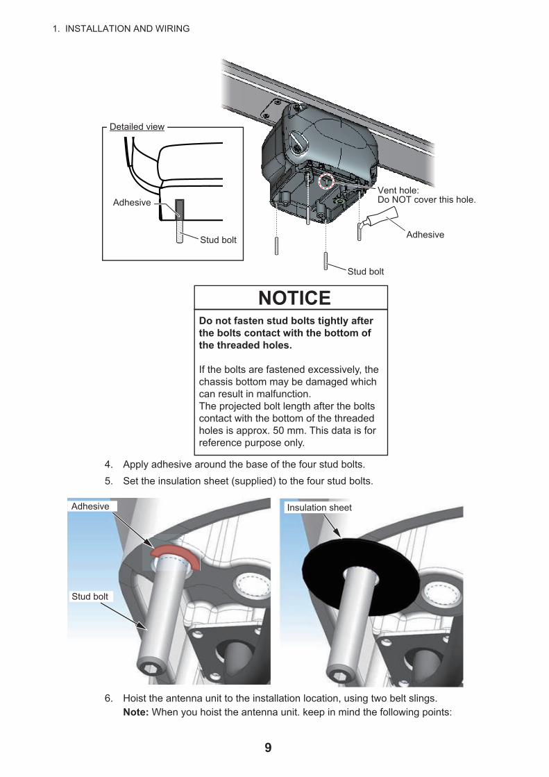
4. Apply adhesive around the base of the four stud bolts.
5. Set the insulation sheet (supplied) to the four stud bolts.
6. Hoist the antenna unit to the installation location, using two belt slings.Note: When you hoist the antenna unit. keep in mind the following points:
Stud bolt
Adhesive
Detailed view
Vent hole:Do NOT cover this hole.Adhesive
Stud bolt
Do not fasten stud bolts tightly after the bolts contact with the bottom of the threaded holes.
If the bolts are fastened excessively, the chassis bottom may be damaged which can result in malfunction.The projected bolt length after the bolts contact with the bottom of the threaded holes is approx. 50 mm. This data is for reference purpose only.
NOTICE
Adhesive
Stud bolt
Insulation sheet
9

1. INSTALLATION AND WIRING
• When you hoist the antenna unit, set two belt slings to the radiator bracket. Do not set the belt slings to the radiator, the radiator may get damaged.
• Hoist the antenna unit slowly. If the antenna unit is hoisted too quickly, the bracket can be damaged.
7. Place the antenna unit on the mounting platform with the BOW mark on the unit aligned with the ship’s bow.
8. Secure the antenna unit, using the supplied flat washers (M12, 4 pcs), spring washers (M12, 4 pcs), and hex. nuts (M12, 8 pcs).
Belt sling (2 pcs)
OK: Belt slings are set to the radiator bracket. WRONG: Belt slings are set to the radiator.
BOW markBOW mark
BowBow
Flat washer
Spring washer
Hex. nut
10

1. INSTALLATION AND WIRING
9. Apply adhesive to the flat washers, spring washers, and hex. nuts.
1.6 Wiring
Wiring considerations
• Turn the power at the switchboard off before beginning the wiring.
• Insert the 10 A fuse to the fuse holder (supplied with the cable assembly) when in-stalling with 15 m, 20 m and 30 m cables. When installing with 10 m cables, the fuse to be used will be different according to the voltage of ship’s main. Use the 15 A fuse for 12 VDC ship’s main. Use the 10 A fuse for 24 VDC ship’s main. Also, attach the supplied fuse rating label to the fuse holder. For details, see “How to Replace the Fuse” (C32-01604).
• The cable assembly and power/LAN cables have connector(s). Do NOT cut the ca-ble assembly and power/LAN cables even if the cables are run through a radar mast.
• When you replace the DRS4A/6A/12A/25A with the DRS6A-NXT/DRS12A-NXT/DRS25A-NXT, the existing cable cannot be used. Use only the cable assembly sup-plied with this radar sensor.
Adhesive
Insulation sheet
Flat washerSpring washer
Hex. nut
Stud bolt
Detailed view
Power/LAN cable:Pre-attached to the antenna unit.
Cable assembly
11

1. INSTALLATION AND WIRING
1. Unfasten two screws, circled in the following figure, to remove the cable cover.
2. Connect the cable assembly (supplied) to the power/LAN cable that is pre-at-tached to the antenna unit.
3. Wrap the junction of the connectors with self-vulcanizing tape and vinyl tape (local supply) for waterproofing as follows:
4. As shown in the figure below, secure the ground wire from the ship's ground (IV-2sq, local supply) and ground wire from the antenna unit, using the terminal screw (M4x10) that is pre-attached to the cable cover.
Cable coverCable cover
Self-vulcanizing tape
1) Wrap the junction of the connectors with one layer of self-vulcanizing tape.
2) Change wrap direction and wrap one layer of the self-vulcanizing tape again.
Self-vulcanizing tape
3) Wrap one layer of the vinyl tape over the self-vulcanizing tape.
Vinyl tape
4) Change wrap direction and wrap one layer of the vinyl tape again.
Vinyl tape
Ground wire from the ship’s ground
*: Pre-attached to the cable cover.
Ground wire* from the antenna unit
Cable coverTerminal screw*
12

1. INSTALLATION AND WIRING
5. Apply adhesive to the ground terminal after fastening the terminal screw.
6. Secure the ground wire to the ship’s ground.The figures shown below are examples for grounding.
7. Secure the cable assembly to the cable cover with the cable ties (local supply) as shown in the figure below.
8. Reattach the cable cover.
9. Connect the LAN connector of the cable assembly to a LAN port on the FURUNO Multi Function Display or Ethernet HUB.Note 1: Do not connect the LAN connector to on-board LAN.
Adhesive
Ex.1 Ex.2Adhesive AdhesiveHex. bolt
Flat washer
Flat washerSpring washerHex. nut
Ground wireGround wire
Hex. nutSpring washer
Flat washer
Hex. nut
Weld here.
Fix the cable to this cable clamp, using a cable tie.Fix the cable to this cable clamp, using a cable tie.
Ground wire from the ship's groundGround wire from the ship's ground
Cable assemblyCable assembly
Power/LAN cablePower/LAN cable
Ground wire from the antenna unitGround wire from the antenna unit
If the cable is run through a radar mast and the bottom of the unit, fix the cable to this cable clamp.
If the cable is run through a radar mast and the bottom of the unit, fix the cable to this cable clamp.
Cable cover - bottom view
13

1. INSTALLATION AND WIRING
Note 2: When LAN cable extension is needed, use the optional LAN cable (MOD-Z072) and joint box (TL-CAT-012). After connection is completed, wrap the con-nector with vinyl tape to waterproof the LAN connector.
10. Connect the power wires to the ship’s battery.
• Red wire: Connect to the positive terminal. The red wire has the fuse holder.
• Blue wire: Connect to the negative terminal.
• Black wire: The black wire is a shielding wire for grounding.
Note 1: The antenna unit has no power switch. Connect the antenna unit to a dis-tribution switchboard with a switch for power control.
Note 2: The antenna unit cannot accept input voltage of more than 24 VDC.
Note 3: Power is supplied to the antenna unit even when the power is shut off at the display unit. If the radar is not to be used for an extended period, shut off the radar from the breaker.
Cable assemblyLAN connector
Ethernet HUBOR
FURUNO Multi Function Display
Joint box
LAN cable
To antenna unit
Cable assemblyShield
Distribution
switchboard
Ship's battery
Fuse holder
RedBlue
Black
14

2. INITIAL SETUP
Vessels equipped with SC-50/60/110/120
For better results when using the target analyzer function, an appropriate time need to be set in the [SMOOTH S/C] menu. When the time set in this menu is too long, the landmass can be judged as approaching target and displayed in red while accelerat-ing, decelerating or turning. If this symptom occurs too often, shorten the time in [SMOOTH S/C] menu.
Note: Instability of COG and SOG can be larger when the [SMOOTH S/C] time be-comes shorter. Set the time avoiding the influence to other navigational equipment, such as GPS plotter and autopilot.
Installation with Multi Function Displays
This radar series is compatible with the FURUNO Multi Function Displays and soft-ware version combinations shown below. Combination with other models may not op-erate properly.
• TZT9, TZT14 and TZTBB: Version 6.01 or laterTZTL12F and TZTL15F and TZT2BB: Version 6.21 or laterTZT12F, TZT16F and TZT19F: Version 1.05 or later
Turn on the antenna unit and FURUNO Multi Function Display. Initial setup for this an-tenna must be done on the FURUNO Multi Function Display.
Before turning on the radar, be sure no one is near the antenna.
Prevent the potential risk of being struck by the rotating antenna, which can result in serious injury or death.
WARNINGThe radar antenna emits electromagnetic radio frequency (RF) energy which can be harmful, particularly to your eyes. Never look directly into the antenna aperture from a close distance while the radar is in operation or expose yourself to the transmitting antenna at a close distance.Distances at which RF radiation levels of 100, 50 and 10 W/m2 exist are given in the table below.
N/AXN10A 0.7 mN/A
100 W/m2 50 W/m2 10 W/m2Radiator
XN12A
XN13A
N/A 0.6 mN/A
N/A 0.4 mN/A
100 W/m2 50 W/m2 10 W/m2Radiator
XN12A
XN13A
0.2 m 1.9 m0.5 m
0.15 m 1.8 m0.4 m
DRS6A-NXT DRS12A-NXT
100 W/m2 50 W/m2 10 W/m2Radiator
XN12A
XN13A
0.3 m 2.8 m0.47 m
0.2 m 2.65 m0.3 m
DRS25A-NXT
15

2. INITIAL SETUP
2.1 Initial Setup for TZT9/TZT14/TZTBB1. Press the Home key (or tap the Home icon).
2. Select [Menu] on the menu icon bar to open the main menu.
3. Select [Radar].
4. Select [Radar Source] on the [Menu Radar] sub menus, then select the radar type connected.Note: If the antenna unit is connect-ed but does not appear in the [Ra-dar Source] list, close the list and open it again. The name of the an-tenna unit should appear with a check mark, as in the example to the right.
5. Drag the [Menu Radar] sub menus to find the menu item [Radar Initial Setup].
6. Set the items referring to the table shown below
Menu Radar (Radar Initial Setup)Menu item Description
[Antenna Rotation] Select the antenna rotation speed.[Antenna Heading Align] See "How to align the antenna heading" on page 17.[Main Bang Suppression] If main bang appears at the screen center, slide the circle
icon, while watching the radar echo on the left-side of the display, until the main bang disappears.
[Enable Sector Blanking]/[Enable Sector Blanking2]
Up to two sectors may be selected for blanking (no trans-mission). Select [ON] to enable this feature. Set the start and end angles (0° to 359°).
[Antenna Height] Select the height of the antenna above the waterline.
RDxxxxxx - DRS6A-NXT
RDxxxxxx - DRS6A-NXT
Display example
Title
16

2. INITIAL SETUP
How to align the antenna heading
You have mounted the antenna unit facing straight ahead in the direction of the bow. Therefore, a small but conspicuous target dead ahead visually should appear on the heading line (zero degrees).
You may observe a minor bearing error on the display. This is due to the difficulty in orienting the radar accurately. The following adjustment will compensate for the error.
[Antenna Length] Selects the length of the antenna. RezBoost function re-flects the selection of this menu item.
[Antenna Longitudinal Po-sition]
Referring to the figure on the right, enter the ra-dar antenna positioning bow-stern (Longitudi-nal) and port-starboard (Lateral) position from the origin.
[Antenna Lateral Position (-Port)]
[Radar Monitoring] Display various information regarding the connected ra-dar.
[ARPA Advanced Settings] For service technician only. Do not change these settings. This menu item is available when setting the radar in transmit.
[TX Channel] Select [1],[2] or [3], the channel where the interference is smallest.
[Target Analyzer Mode] You can emphasize rain clutter or target echoes when the target analyzer is active. Select [Rain] or [Target] as ap-propriate.
[Auto Acquire by Doppler] When selecting [ON], approaching targets within 3 NM from own ship are automatically acquired by the Doppler calculated from the radar echo.
[Hardware Factory Default] Resets the radar selected at [Radar Source] to factory de-fault.
[Reset Default Settings] Resets [Radar] menu settings to default.
Menu item Description
OriginOrigin
000 010 020030
040
050
060
070
080
090
100
110
120
130
140150
160170180190200210
220
230
240
250
260
270
280
290
300
310
320330
340 350 000 010 020030
040
050
060
070
080
090
100
110
120
130
140150
160170180190200210
220
230
240
250
260
270
280
290
300
310
320330
340 350
Correct bearing of target(relative to heading)
a
Displayedpositionof target
aTarget
Antenna oriented to port
Picture appears with clockwise deviation.
Displayed position of target
bTarget
b
Correct bearing of target(relative to heading)Antenna oriented
to starboardPicture appears with counterclockwise deviation.
17

2. INITIAL SETUP
1. Select a range between 0.125 and 0.25 NM and set the mode to “head up“.You can select a range by a pinch action. The range and range ring interval ap-pear at the bottom left of the screen.
For TZTBB, you can also control the range in the operation as follows. Tap the radar scale box at the bottom left-hand corner of the screen to display the slider bar. Drag the circle icon to set the range scale.
2. Turn the vessel’s bow toward a target.
3. Press the Home key (or tap the Home icon), then select [Menu] icon, [Radar], and [Antenna Heading Align] in that order to show the numeric software keyboard.
4. Key in the offset value so that the target is at the very top of the screen (setting range: +/- 0° to 180°, +: clockwise direction, -: counterclockwise direction), then tap [Save].
5. Confirm that the target echo is displayed at correct bearing on the screen.
2.2 Initial Setup for TZTL12F/TZTL15F/TZT2BB/TZT12F/TZT16F/TZT19F1. Tap the [Home] icon to show the home screen and display mode settings.
2. Tap [Radar] from the [Settings] menu.
3. Tap [Radar Source], then select the appropriate antenna unit.Note: If the antenna unit is connected but does not appear in the [Radar Source] list, close the list and open it again. The name of the antenna unit should appear with a check mark, as in the example below.
4. Drag the [Radar] menu display the menu item [Radar Initial Setup], then tap [Radar Initial Setup].
1
Range Range ring interval
Range indications
Zoom outZoom in
Pinch action
Tap the area circled in the dashed line to display the slider bar.Note: You can switch between transmit and stand-by by tapping the right side of the radar scale box.
Drag the circle icon to set the range scale.
Slider bar
Zoom in
Zoom out
4NMCurrent range
RDxxxxxx - DRS6A-NXT
Display example for DRS6A-NXT
18

2. INITIAL SETUP
5. Referring to the tables below, set up the radar.
[Radar] menu - [Radar Initial Setup]
[Radar] menu - [Antenna Position]
How to align the antenna heading
You have mounted the antenna unit facing straight ahead in the direction of the bow. Therefore, a small but conspicuous target dead ahead visually should appear on the heading line (zero degrees).
You may observe a minor bearing error on the display. This is due to the difficulty in orienting the radar accurately. The following adjustment will compensate for the error.
Menu item Description[Antenna Rotation] Select the antenna rotation speed.[Antenna Heading Align] See "How to align the antenna heading" on page 19.[Main Bang Suppression] If main bang appears at the screen center, slide the circle
icon so that the main bang disappears, while watching the radar echo at the left-hand side of the display.
[Enable Sector Blanking] Up to two sectors may be selected for blanking (no trans-mission). Select [ON] to enable this feature. Set the start and end angles (0° to 359°).
[Enable Sector 2 Blanking]
Menu item Description[Longitudinal (from bow)] Referring to the figure on the right, enter the ra-
dar antenna positioning bow-stern (Longitudi-nal) and port-starboard (Lateral) position from the origin.
[Lateral (-Port)]
[Antenna Height] Selects the height of the antenna above the waterline.[Antenna Length] Selects the length of the antenna. RezBoost function re-
flects the selection of this menu item.[Radar Monitoring] Display various information regarding the connected ra-
dar.[TX Channel] Select [1], [2] or [3], the channel where the interference is
smallest.[Target Analyzer Mode] You can emphasize rain clutter or target echoes when the
target analyzer is active. Select [Rain] or [Target] as ap-propriate.
[Auto acquire by Doppler] When selecting [ON], approaching targets within 3 NM from own ship are automatically acquired by the Doppler calculated from the radar echo.
[Set Hardware To Factory Default]
Resets the radar selected at [Radar Source] to factory de-fault.
[Reset Default Settings] Resets [Radar] menu settings to default.
OriginOrigin
19

2. INITIAL SETUP
1. Set your radar with 0.125 and 0.25 NM range and the head up mode.The range scale can be selected two ways, as shown below. The slider bar can be shown or hidden with [Show Scale Slider] in the [Settings] - [Radar] menu.
2. Turn the vessel’s bow toward a target.
3. Tap the [Home] icon to show the home screen and display mode settings.
4. Tap [Radar] to show the [Radar] menu.
5. Drag the [Radar] menu to show the [RADAR INITIAL SETUP] menu.
6. Tap [Antenna Heading Align].
7. Key in the offset value so that the target is displayed at the very top of the screen (setting range: +179.9° to -180°, +: clockwise direction, -: counterclockwise direc-
tion), then tap the icon.
8. Confirm that the target echo is displayed at correct bearing on the screen.
000 010 020030
040
050
060
070
080
090
100
110
120
130
140150
160170180190200210
220
230
240
250
260
270
280
290
300
310
320330
340 350 000 010 020030
040
050
060
070
080
090
100
110
120
130
140150
160170180190200210
220
230
240
250
260
270
280
290
300
310
320330
340 350
Correct bearing of target(relative to heading)
a
Displayedpositionof target
aTarget
Antenna oriented to port
Picture appears with clockwise deviation.
Displayed position of target
bTarget
b
Correct bearing of target(relative to heading)Antenna oriented
to starboardPicture appears with counterclockwise deviation.
Zoom in Zoom out
Method 1: Pinch screen
Method 2: Drag slider(or tap bar or +, - icons)
3 NM
Zoom inZoom in
Zoom outZoom out
20

3. MAINTENANCE, TROUBLE SHOOTING
Periodic checks and maintenance are important for proper operation of any electronic system. This chapter contains maintenance and troubleshooting instructions to be fol-lowed to obtain optimum performance and the longest possible life of the equipment. Before attempting any maintenance or troubleshooting procedure, please review the safety information below and at the front of this manual. If you cannot restore normal operation after following the troubleshooting procedures, do not attempt to check in-side any unit; there are no user serviceable parts inside. Contact your dealer to check the equipment.
Do not apply paint, anti-corrosive sealant or contact spray to coating or plastic parts of the equipment.
Those items contain organic solvents that can damage coating and plastic parts, especially plastic connectors.
WARNING
NOTICE
Do not open the equipment.
Hazardous voltage which can cause electrical shock exists inside the equipment. Only qualified personnel should work inside the equipment.
Turn off the antenna unit before servicing the unit. Post a warning sign near the switch indicating it should not be turned on while the antenna unit is being serviced.
Prevent the potential risk of being struck by the rotating antenna.
A transmitting radar antenna emits electromagnetic waves, which can be harmful, particularly the eyes.
Wear a safety belt and hard hat when working on the antenna unit.
Serious injury or death can result if someone falls from the radar antenna mast.
21

3. MAINTENANCE, TROUBLE SHOOTING
3.1 MaintenanceRegular maintenance is important for good performance. Check the points mentioned below every 3 to 6 months to keep the antenna unit in good working order.
Check point
Action Remedy, remarks
Check points every 3 to 6 monthsCable Check that all cables are firmly
connected and are not damaged.• Connect a cable if it has loosened.• Replace damaged cables.
Exposed bolts and nuts
Check that bolts and nuts are not corroded and are securely fas-tened.
• Replace corroded bolts.• Tighten loosened bolts. • Coat new bolts with adhesive.
Adhesive on the bolts, nuts and cable clamps
Check that adhesive has not fall-en off or cracked.
• Deteriorated adhesive may cause water leakage into the unit or corro-sion of the bolts, nuts and cable clamps.
• If the adhesive is fallen off or cracked, apply adhesive to cover the spot.
• If the adhesive is severely deterio-rated, peel off the adhesive and ap-ply the adhesive again on the spot.
Radiator Dust, dirt and salt deposits on the radiator cause signal attenu-ation, resulting in loss of sensitiv-ity.
• Wipe radiator with a freshwater-moistened cloth.
• The radiator is made of AES (Acry-lonitrile-Ethylene-Styrene) resin. Therefore, do not used gasoline, benzene and the like to clean the ra-diator.
• If the radiator is iced, use a wooden or plastic headed hammer to re-move the ice. DO NOT use a steel hammer.
Ground connection
Check for tight connection and rust.
• Fasten if loosened.• Remove rust if present.
Check points every yearCheck the scanner unit for rust, corrosion and chipped paint.
• If the scanner unit has rusted or the paint has chipped, paint the affected area of the scanner unit.
• Do not paint the antenna (see figure below). Paint on the antenna can cause loss of sensitivity and crack the antenna.
: Do NOT paint. : Painting area
22

3. MAINTENANCE, TROUBLE SHOOTING
3.2 TroubleshootingThe table below provides simple troubleshooting procedures to restore normal opera-tion. If you cannot restore normal operation, contact your dealer for advice.
3.3 Replacement of FuseThe fuse protects the antenna unit from overcurrent and equipment fault. If you cannot turn on the power, check the fuse to see if it has blown. If the fuse has blown, find the reason before you replace the fuse. If the fuse blows again after the replacement, con-tact your dealer.
Problem RemedyThe multi function display can-not control the radar.
• Check that all cables are tightly fastened.• Check if the radar source setting is correct.• Check if the fuse of the cable assembly has blown.• Check that the power supply is compatible with the
voltage rating of the antenna unit.Marks and characters appear, but echoes do not appear.
• Check that the antenna cable is tightly fastened.• Check the cables for damage.
Picture is not updated or the picture freezes.
• Check that all cables are tightly fastened.• Check the cables for damage.• If the picture has frozen, reboot the multi function
display.You changed the range, but the radar picture does not change.
• Try to change the range again.• Reboot the multi function display.
Poor discrimination in range. • Adjust the sea control.Range rings are not displayed. • Check if the range rings is turned on in the menu.You set the radar in the transmit state. The "TX screen" appears momentarily, but the radar soon goes into stand-by.
• The overload protection has activated. To restore normal operation, turn off all equipment in the net-work. Wait a few seconds then turn on all the equip-ment.
Name Type Code No. Remarks
Fuse FRU-60V-FU-10A
000-194-014-1010 A fuse For 24 VDC Ship’s Main
FRU-60V-FU-15A
000-194-915-1015 A fuse For 12 VDC Ship’s Main
WARNINGWARNINGUse the proper fuse.
Use of a wrong fuse can cause fire or damage the equipment. Fuse holder
How to replace the fuseOpen the fuse holder cover and replace the fuse. Then close the cover.
Cable assembly
23

3. MAINTENANCE, TROUBLE SHOOTING
3.4 Life of Parts
Antenna Motor
When an antenna motor reaches the end of its life, the antenna’s rotation may stop or abnormal noise sounds from the antenna unit. If such symptom occurs, contact your dealer about replacement of the antenna motor.
Name Type Code No. Approx. Life
Antenna Motor RSB-134 MOTOR 001-436-400 10,000 hours
24

AP-1
APPENDIX 1 RADIO REGULATORY INFORMATION
USA-Federal Communications Commission (FCC)
This device complies with part 15 of the FCC Rules. Operation is subject to the following two conditions:(1) This device may not cause harmful interference, and(2) This device must accept any interference received, including interference that may cause undesired
operation. Any changes or modifications not expressly approved by the party responsible for compliance could void the user's authority to operate the equipment.
Caution: Exposure to Radio Frequency Radiation• This equipment complies with FCC radiation exposure limits set forth for an uncontrolled environment
and meets the FCC radio frequency (RF) Exposure Guidelines in Supplement C to OET65.• This equipment should be installed and operated keeping the radiator away from a person's body at
the minimum distances shown in the table below.
• This device must not be co-located or operating in conjunction with any other antenna or transmitter.
Innovation, Science and Economic Fevelopment Canada (ISED)
This device complies with Industry Canada licence-exempt RSS standard(s). Operation is subject to the following two conditions:(1) This device may not cause interference, and(2) This device must accept any interference, including interference that may cause undesired operation
of this device.
Le présent appareil est conforme aux CNR d'Industrie Canada applicables aux appareils radio exempts de licence. L'exploitation est autorisée aux deux conditions suivantes:(1) l'appareil ne doit pas produire de brouillage, et(2) l'utilisateur de l'appareil doit accepter tout brouillage radioélectrique subi, même si le brouillage est
susceptible d'en compromettre le fonctionnement.
Caution: Exposure to Radio Frequency RadiationThis equipment complies with IC radiation exposure limits set forth for an uncontrolled environment and meets RSS-102 of the IC radio frequency (RF) Exposure rules. This equipment should be installed and operated keeping the radiator away from a person's body at the minimum distances shown in the table below.
Cet équipement est conforme aux limites d'exposition aux rayonnements énoncées pour un environnement non contr êolé et respecte les règles d'exposition aux fréquences radioélectriques (RF) CNR-102 de l'IC. Cet équipement doit etre installé et utilise en gardant une distance de 70 cm (DRS6A -NXT (RTR-119)), 190 cm (DRS12A-NXT (RTR-125)), 280 cm (DRS25-NXT (RTR-126)) ou plus entre le dispositif rayonnant et le corps.
To reduce potential radio interference to other users, the antenna type and its gain should be so chosen that the equivalent isotropically radiated power (EIRP) is not more than that required for successful communication.
70 cmDRS6A-NXTSafety DistanceAntenna Model
DRS12A-NXTDRS25A-NXT
190 cm280 cm
Transceiver UnitRTR-119
RTR-125RTR-126
70 cmDRS6A-NXTSafety DistanceAntenna Model
DRS12A-NXTDRS25A-NXT
190 cm280 cm
Transceiver UnitRTR-119
RTR-125RTR-126

FURUNO DRS6A/12A/25A-NXT
SP - 1 E3668S01E-M 211026
SPECIFICATIONS OF RADAR SENSOR DRS6A/12A/25A-NXT
1 ANTENNA UNIT 1.1 Antenna type Slotted waveguide array 1.2 Antenna length 3.4 ft (XN10A), 4 ft (XN12A), 6 ft (XN13A) 1.3 Horizontal beam width 2.3° (XN10A), 1.9° (XN12A), 1.35° (XN13A)
RezBoost effective beam width* 1.15° to 2.3° (XN10A), 0.95° to 1.9° (XN12A), 0.7° to 1.35° (XN13A) *: RezBoost provides better echo resolution, in a manner similar to adjusting the beam width.
1.4 Vertical beam width 22° 1.5 Antenna gain 27.5 dBi (XN10A), 28.0 dBi (XN12A), 29.5 dBi (XN13A) 1.6 Polarization Horizontal 1.7 Rotation 24/36/48 rpm range coupled or 24 rpm fixed 1.8 Relative wind load 70 kn or less 2 RADAR FUNCTION 2.1 Tx frequency 3 channel, auto/manual selectable
Ch.1 (P0N/Q0N) 9380/9400 MHz Ch.2 (P0N/Q0N) 9400/9420 MHz Ch.3 (P0N/Q0N) 9420/9440 MHz
2.2 Output power DRS6A-NXT 25 W DRS12A-NXT 100 W DRS25A-NXT 200 W
2.3 Duplexer Ferrite circulator with diode limiter 2.4 Intermediate frequency 83.75/103.75 MHz (P0N/Q0N) 2.5 Range scale 0.0625/0.125/0.25/0.5/0.75/1/1.5/2/3/4/6/8/12/16/24/32/36/48/64/
72/96* *: DRS12A/25A-NXT only 2.6 Pulse length P0N: 0.04 to 1.2 s, Q0N: 5 to 48 s 2.7 Pulse repetition rate
DRS6A-NXT 700 to 2000 Hz approx. DRS12A /25A-NXT 550 to 2000 Hz approx.
2.8 Minimum range DRS6A-NXT 10 m DRS12A/25A-NXT 6 m
2.9 Range resolution 10 m 2.10 Range accuracy Within 1% of range in use 2.11 Bearing accuracy Within ±1° 2.12 Warm-up time Nil 2.13 Target tracking (TT) Auto or manual acquisition: 100 targets between 0.1 and 24 NM
Past position: 5/10 pts on all activated targets Vector time: 1 to 60 min.
3 INTERFACE
LAN: 1 port, Ethernet, 100Base-TX, RJ45

FURUNO DRS6A/12A/25A-NXT
SP - 2 E3668S01E-M 211026
4 POWER SUPPLY
DRS6A-NXT 12/24 VDC (10.8-15.6/21.6-31.2V): 9.5/5.0 A max. DRS12A-NXT 24 VDC (21.6-31.2V): 5.0 A max. DRS25A-NXT 24 VDC (21.6-31.2V): 5.6 A max.
5 ENVIRONMENTAL CONDITIONS 5.1 Ambient temperature -25°C to +55°C (storage: -30°C to +70°C) 5.2 Relative humidity 95% or less at +40°C 5.3 Degree of protection IP56 5.4 Vibration IEC 60945 Ed.4 6 UNIT COLOR
N9.5

03HZ-X-9851 -3
RSB-137-119-E, RSB-137-119-J-12A/13A
N A M E O U T L I N E DESCRIPTION/CODE № Q'TY
1/1A C K I N G L I S TP
ユニット UNIT
空中線本体部
SCANNER UNITRSB-137-119-*
000-038-054-00
1
**
予備品 SPARE PARTS
予備品
SPARE PARTSSP03-19501
001-513-950-00
1
工事材料 INSTALLATION MATERIALS
工事材料
INSTALLATION MATERIALSCP03-37101
001-426-290-00
1
図書 DOCUMENT
レーダーセンサー型紙
RADAR SENSOR TEMPLATEC32-02103-*
000-198-927-1*
1
装備要領書
INSTALLATION MANUALIM*-36680-*
000-197-935-1*
1
**
技適認証要領
APPLICATION GUIDEJ32-02005-*
000-197-937-1*
1
(*1)
1.コ-ド番号末尾の[**]は、選択品の代表コードを表します。
CODE NUMBER ENDING WITH "**" INDICATES THE CODE NUMBER OF REPRESENTATIVE MATERIAL.
2.(*1)の書類は、和文仕様専用
(*1) MARKED DOCUMENTS ARE FOR JAPANESE SET ONLY.
(略図の寸法は、参考値です。 DIMENSIONS IN DRAWING FOR REFERENCE ONLY.)
C3668-Z01-D
A-1
03IG-X-9851 -2
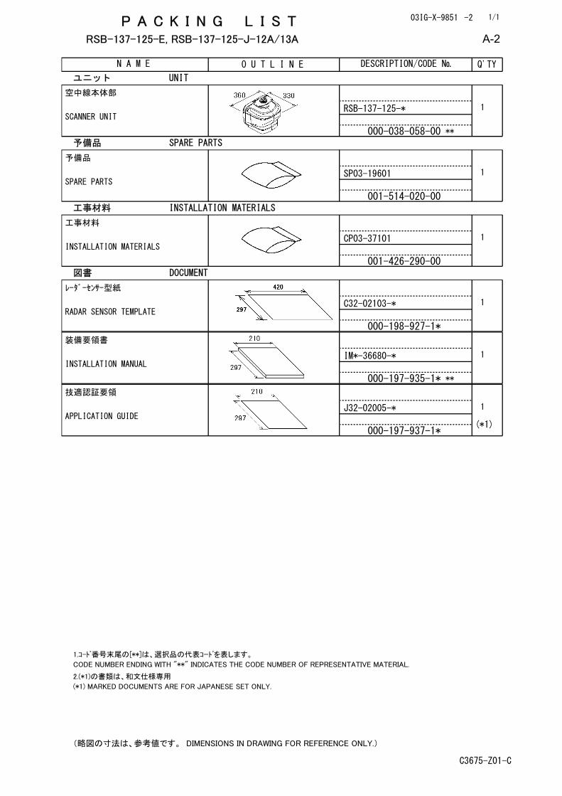
RSB-137-125-E, RSB-137-125-J-12A/13A
N A M E O U T L I N E DESCRIPTION/CODE № Q'TY
1/1A C K I N G L I S TP
ユニット UNIT
空中線本体部
SCANNER UNITRSB-137-125-*
000-038-058-00
1
**
予備品 SPARE PARTS
予備品
SPARE PARTSSP03-19601
001-514-020-00
1
工事材料 INSTALLATION MATERIALS
工事材料
INSTALLATION MATERIALSCP03-37101
001-426-290-00
1
図書 DOCUMENT
レーダーセンサー型紙
RADAR SENSOR TEMPLATEC32-02103-*
000-198-927-1*
1
装備要領書
INSTALLATION MANUALIM*-36680-*
000-197-935-1*
1
**
技適認証要領
APPLICATION GUIDEJ32-02005-*
000-197-937-1*
1
(*1)
1.コ-ド番号末尾の[**]は、選択品の代表コードを表します。
CODE NUMBER ENDING WITH "**" INDICATES THE CODE NUMBER OF REPRESENTATIVE MATERIAL.
2.(*1)の書類は、和文仕様専用
(*1) MARKED DOCUMENTS ARE FOR JAPANESE SET ONLY.
(略図の寸法は、参考値です。 DIMENSIONS IN DRAWING FOR REFERENCE ONLY.)
C3675-Z01-C
A-2

03IG-X-9852 -2
RSB-137-126-E, RSB-137-126-J-12A/13A
N A M E O U T L I N E DESCRIPTION/CODE № Q'TY
1/1A C K I N G L I S TP
ユニット UNIT
空中線本体部
SCANNER UNITRSB-137-126-*
000-038-062-00
1
**
予備品 SPARE PARTS
予備品
SPARE PARTSSP03-19601
001-514-020-00
1
工事材料 INSTALLATION MATERIALS
工事材料
INSTALLATION MATERIALSCP03-37101
001-426-290-00
1
図書 DOCUMENT
レーダーセンサー型紙
RADAR SENSOR TEMPLATEC32-02103-*
000-198-927-1*
1
装備要領書
INSTALLATION MANUALIM*-36680-*
000-197-935-1*
1
**
技適認証要領
APPLICATION GUIDEJ32-02005-*
000-197-937-1*
1
(*1)
1.コ-ド番号末尾の[**]は、選択品の代表コードを表します。
CODE NUMBER ENDING WITH "**" INDICATES THE CODE NUMBER OF REPRESENTATIVE MATERIAL.
2.(*1)の書類は、和文仕様専用
(*1) MARKED DOCUMENTS ARE FOR JAPANESE SET ONLY.
(略図の寸法は、参考値です。 DIMENSIONS IN DRAWING FOR REFERENCE ONLY.)
C3676-Z01-C
A-3

B C D F
UD
UN
O
2
�,
�
200±
0,5
lm�
□
VENT
HOLE
Ill!M1\
CW5t!JtJ
c; m! �
18 l
FIXING
HOLE
S (DE
PTH:
18)
4-M 1
2
'r-J"J
v@A
□ 03
1 CA
BLE E
NTRY
�:i:U
U'sz
NAME
PLAT
E 7
-7-ft
im-=f
GND T
ERMIN
AL
'T -
7--Ji,,
CO.S
ri)
CABL
E /
rt 300
15
5 aia
1 ) t�
JE'.$1�
"1�
��
,;t�
1 ,:::
J:: �
o
330
2 )
# l:f.l
"tj"�
l;t i'l'J
, if -
I:::'.' 7'
� lffl
"tj"�
c 1"
� o
3)•
M�
M1 2
"1�
¥�
��
�ffl
��
co
160
.3.
.4
[g] '2i
cp I li
' CE
NTER
OF RO
T A TIO
N
¢
ffiB §
h l□l
� 0�
@ii
�
B□
vl
1//
�%
2t>
li NT[NN4
CL [,� llfJ
( &
) V
/
li R1iNcroJ;
I//
.5
� c:p
� �
c Al
AN
TENN
A LEN
GTH (
A)
�2
TABL
E 2
XN10
A I X
N12A
I
XN13
A 10
36±1
0 112
55±1
0 11
795±
10
1200
I
1400
I
1940
20
I 21
I 23
�1
TABL
E 1
-t�
IR?}
(MM
) �&
(MM)
DIM
ENSIO
N
TOLERANCE
L'50
±1
.5
50 <L
,100
±2
,5
100 <
L ,50
0 ±3
50
0 <L ,
1000
±4
10
00 < L
, 200
0 ±5
[Q�
to,
! ,c
l�□
lD
"Cj "Cj-
L 26
5,7
360
NOTE
1.
TABL
E 1 I
NDIC
ATES
TOLE
RANC
E OF
DIME
NSIO
NS IJ
HICH
IS N
OT S
PECI
FIED
,
... 31
/-"'""
T.YA
II\SA
Kl -
--
--
� -
--
111IlI
RSB-
137
Ill£CKED
311 Ju11
2020
H.MAK
I I
ta
� cp
W gJ3
MVEll 3
/Aug
/202
0 H
,MA
KI
DR�A�
;--
-1-
--
$1�-tj"
� 2,
#: MI
NIMU
M SE
RVIC
E CL
EARA
NCE.
3, US
E M1
2 ST
UD B
DL T
FDR
FIXI
NG T
HE U
NIT,
srJ1I
, ,n
I� �
2•J1
I INN£
AN
TENN
A UNI
T llVliJh
M
rr
n
rn,
n
IKttllJ.
n'l
,n
,
'lnnr
"
I
OUTL
INE
D RAIJ
JNG
=--s�
� F
UR
UN
O E
LE
CT
RIC
CO
., L
TD
.
D-1

3/Aug/2020H.MAKI
Hiro
mas
a M
aki
電子署名者
: H
irom
asa
Mak
i 日付
: 20
20.0
8.03
11:
14:3
8 +0
9'00
'
D-2

2/Dec/2020H.MAKI
Hiro
mas
a M
aki
電子署名者
: H
irom
asa
Mak
i 日付
: 20
20.1
2.02
16
:20:
23 +
09'0
0'
S-1

Declaration of Conformity
Bulgarian(BG)
Spanish(ES)
Czech(CS)
Danish(DA)
German(DE)
Estonian(ET)
Greek(EL)
English(EN)
French(FR)
Croatian(HR)
Italian(IT)
Latvian(LV)
Pilns ES/AK atbilstības deklarācijas teksts ir pieejams šādā interneta vietnē:
Με την παρούσα η Furuno Electric Co., Ltd., δηλώνει ότι ο προαναφερθένταςραδιοεξοπλισμός πληροί την οδηγία 2014/53/ΕΕ, SI 2017/1206.Το πλήρες κείμενο της δήλωσης συμμόρφωσης EE/UK διατίθεται στην ακόλουθηιστοσελίδα στο διαδίκτυο:
Hereby, Furuno Electric Co., Ltd. declares that the above-mentioned radioequipment type is in compliance with Directive 2014/53/EU, SI 2017/1206.The full text of the EU/UK declaration of conformity is available at the followinginternet address:
Le soussigné, Furuno Electric Co., Ltd., déclare que l'équipement radioélectriquedu type mentionné ci-dessus est conforme à la directive 2014/53/UE, SI 2017/1206.Le texte complet de la déclaration UE/RU de conformité est disponible à l'adresseinternet suivante:
Furuno Electric Co., Ltd. ovime izjavljuje da je gore rečeno radijska oprema tipau skladu s Direktivom 2014/53/EU, SI 2017/1206.Cjeloviti tekst EU/UK izjave o sukladnosti dostupan je na sljedećoj internetskojadresi:
Il fabbricante, Furuno Electric Co., Ltd., dichiara che il tipo di apparecchiaturaradio menzionato sopra è conforme alla direttiva 2014/53/UE, SI 2017/1206.Il testo completo della dichiarazione di conformità UE/RU è disponibile al seguenteindirizzo Internet:
Ar šo Furuno Electric Co., Ltd. deklarē, ka augstāk minēts radioiekārta atbilstDirektīvai 2014/53/ES, SI 2017/1206.
[DRS6A-NXT/DRS12A-NXT/DRS25A-NXT]
EL/GB vastavusdeklaratsiooni täielik tekst on kättesaadav järgmiselinternetiaadressil:
С настоящото Furuno Electric Co., Ltd. декларира, че гореспоменат типрадиосъоръжение е в съответствие с Директива 2014/53/ЕС, SI 2017/1206.Цялостният текст на EC/UK декларацията за съответствие може да се намерина следния интернет адрес:
Por la presente, Furuno Electric Co., Ltd. declara que el tipo de equipo radioeléctricoarriba mencionado es conforme con la Directiva 2014/53/UE, SI 2017/1206.
El texto completo de la declaración de conformidad de la EU/UK está disponible enla siguiente dirección Internet:
Tímto Furuno Electric Co., Ltd. prohlašuje, že výše zmíněné typ rádiovéhozařízení je v souladu se směrnicí 2014/53/EU, SI 2017/1206.Úplné znění EU/SK prohlášení o shodě je k dispozici na této internetové adrese:
Hermed erklærer Furuno Electric Co., Ltd., at ovennævnte radioudstyr er ioverensstemmelse med direktiv 2014/53/EU, SI 2017/1206.EU/UK-overensstemmelseserklæringens fulde tekst kan findes på følgendeinternetadresse:
Hiermit erklärt die Furuno Electric Co., Ltd., dass der oben genannteFunkanlagentyp der Richtlinie 2014/53/EU, SI 2017/1206 entspricht.Der vollständige Text der EU/UK-Konformitätserklärung ist unter der folgendenInternetadresse verfügbar:
Käesolevaga deklareerib Furuno Electric Co., Ltd., et ülalmainitud raadioseadmetüüp vastab direktiivi 2014/53/EL, SI 2017/1206 nõuetele.

Lithuanian(LT)
Hungarian(HU)
Maltese(MT)
Dutch(NL)
Polish(PL)
Portuguese(PT)
Romanian(RO)
Slovak(SK)
Slovenian(SL)
Finnish(FI)
Swedish(SV)
Online Resourcehttp://www.furuno.com/en/support/red_doc
Notice for radiated immunity
O(a) abaixo assinado(a) Furuno Electric Co., Ltd. declara que o mencionadoacima tipo de equipamento de rádio está em conformidade com a Diretiva2014/53/UE, SI 2017/1206.
Den fullständiga texten till EU/Storbritannien-försäkran om överensstämmelse finnspå följande webbadress:
The test for the radiated immunity is performed up to 2.7 GHz only without the special conditionof spot frequency being applied. There is a chance that this equipment may interfere withallocated services in the frequency range of 2.7 GHz to 6 GHz, particularly in harbors, rivers,lake banks, etc.
Úplné EÚ/SK vyhlásenie o zhode je k dispozícii na tejto internetovej adrese:
Furuno Electric Co., Ltd. potrjuje, da je zgoraj omenjeno tip radijske opremeskladen z Direktivo 2014/53/EU, SI 2017/1206.
Furuno Electric Co., Ltd. vakuuttaa, että yllä mainittu radiolaitetyyppi ondirektiivin 2014/53/EU, SI 2017/1206 mukainen.EU/UK-vaatimustenmukaisuusvakuutuksen täysimittainen teksti on saatavillaseuraavassa internetosoitteessa:
Härmed försäkrar Furuno Electric Co., Ltd. att ovan nämnda typ avradioutrustning överensstämmer med direktiv 2014/53/EU, SI 2017/1206.
Celotno besedilo izjave EU/ZK o skladnosti je na voljo na naslednjem spletnemnaslovu:
Prin prezenta, Furuno Electric Co., Ltd. declară că echipamentul radio menționatmai sus este în conformitate cu Directiva 2014/53/UE, SI 2017/1206.Textul integral al declarației de conformitate UE/RU este disponibil la următoareaadresă internet:
Furuno Electric Co., Ltd. týmto vyhlasuje, že vyššie spomínané rádiovézariadenie typu je v súlade so smernicou 2014/53/EÚ, SI 2017/1206.
O texto integral da declaração de conformidade da EU/UK está disponível noseguinte endereço de Internet:
It-test kollu tad-dikjarazzjoni ta' konformità tal-UE/RU huwa disponibblif'dan l-indirizz tal-Internet li ġej:
Hierbij verklaar ik, Furuno Electric Co., Ltd., dat het hierboven genoemde typeradioapparatuur conform is met Richtlijn 2014/53/EU, SI 2017/1206.De volledige tekst van de EU/VK-conformiteitsverklaring kan worden geraadpleegdop het volgende internetadres:
Furuno Electric Co., Ltd. niniejszym oświadcza, że wyżej wymieniony typurządzenia radiowego jest zgodny z dyrektywą 2014/53/UE, SI 2017/1206.Pełny tekst deklaracji zgodności UE/UK jest dostępny pod następującym adreseminternetowym:
Aš, Furuno Electric Co., Ltd., patvirtinu, kad pirmiau minėta radijo įrenginių tipasatitinka Direktyvą 2014/53/ES, SI 2017/1206.Visas ES/JK atitikties deklaracijos tekstas prieinamas šiuo interneto adresu:
Furuno Electric Co., Ltd. igazolja, hogy fent említett típusú rádióberendezésmegfelel a 2014/53/EU, SI 2017/1206 irányelvnek.Az EU/EK-megfelelőségi nyilatkozat teljes szövege elérhető a következő internetescímen:
B'dan, Furuno Electric Co., Ltd., niddikjara li msemmija hawn fuq-tip ta' tagħmirtar-radju huwa konformi mad-Direttiva 2014/53/UE, SI 2017/1206.


The paper used in this manual
is elemental chlorine free.
・FURUNO Authorized Distributor/Dealer
9-52 Ashihara-cho,
Nishinomiya, 662-8580, JAPAN
A : APR 2017.Printed in JapanAll rights reserved.
E6 : DEC . 02, 2021
Pub. No. IME-36680-E6
(TASU ) DRS6A/12A/25A-NXT
0 0 0 1 9 3 4 4 1 1 4