Embed Size (px)
Citation preview
Manual 501-M005
June 2007 Revision 5
www.mcmflow.com
© C O P Y R I G H T 2 0 0 7 R . D . M C M I L L A N C O M P A N Y , I N C .
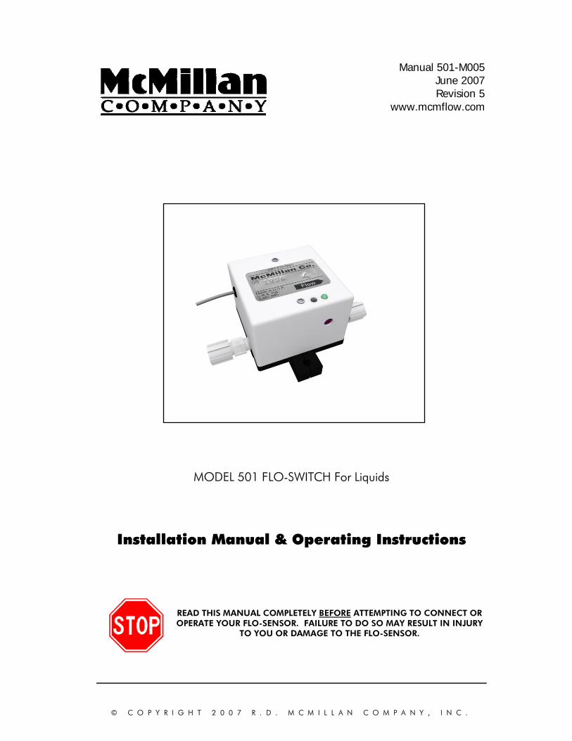
MODEL 501 FLO-SWITCH For Liquids
Installation Manual & Operating Instructions
READ THIS MANUAL COMPLETELY BEFORE ATTEMPTING TO CONNECT OR OPERATE YOUR FLO-SENSOR. FAILURE TO DO SO MAY RESULT IN INJURY
TO YOU OR DAMAGE TO THE FLO-SENSOR.
501-M005, pg. 2 of 26
T A B L E O F C O N T E N T S
A. Introduction ...........................................................................................3
1. Unpacking.........................................................................................3 2. Product Overview And Principle Of Operation ........................................4 3. Non-Standard Products (Z Suffixes)........................................................5
B. Installation.............................................................................................5
1. General Considerations.......................................................................5 2. Mounting The FLO-SWITCH .............................................................7 3. Tubing Connections ............................................................................7 4. Electrical Connections .........................................................................9
a) Overview ..................................................................................9 b) Connecting to the FLO-SWITCH......................................................10 c) Inductive Loads .............................................................................11
C. Operation ...........................................................................................12
1. Start-Up ..........................................................................................12 2. Entrapped Air or Gas ........................................................................12 3. General Operation ...........................................................................12 4. Verifying the Set Point ........................................................................13 5. Adjusting the Set Point .......................................................................14 6. Operating at Flow Rates Outside the Calibrated Flow Range ..................15 7. Zero Adjustments ..............................................................................15 8. Recalibration....................................................................................15 9. Calibrating FLO-SWITCHES for different Liquids....................................15
D. Maintenance And Product Care ..............................................................16
1. General...........................................................................................16 2. Cleaning and Flushing ......................................................................16 3. Returning Units For Repair Or Recalibration..........................................16
E. Part Number Information .......................................................................18
F. Specifications .......................................................................................19
G. Dimensions..........................................................................................20
H. Limited Warranty ..................................................................................22
I. Trouble Shooting Guide ........................................................................25
J. Contacting McMillan.............................................................................26
501-M005, pg. 3 of 26
A. Introduction 1. Unpacking
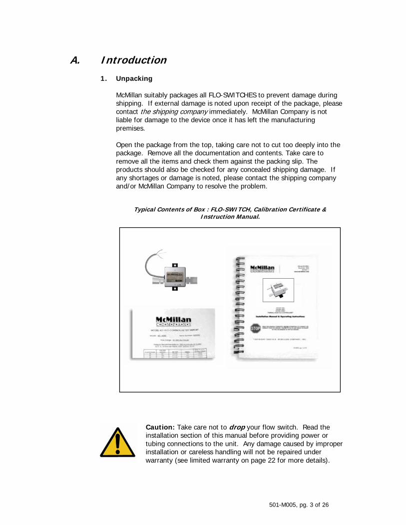
McMillan suitably packages all FLO-SWITCHES to prevent damage during shipping. If external damage is noted upon receipt of the package, please contact the shipping company immediately. McMillan Company is not liable for damage to the device once it has left the manufacturing premises. Open the package from the top, taking care not to cut too deeply into the package. Remove all the documentation and contents. Take care to remove all the items and check them against the packing slip. The products should also be checked for any concealed shipping damage. If any shortages or damage is noted, please contact the shipping company and/or McMillan Company to resolve the problem.
Typical Contents of Box : FLO-SWITCH, Calibration Certificate &
Instruction Manual.
Caution: Take care not to drop your flow switch. Read the installation section of this manual before providing power or tubing connections to the unit. Any damage caused by improper installation or careless handling will not be repaired under warranty (see limited warranty on page 22 for more details).
501-M005, pg. 4 of 26
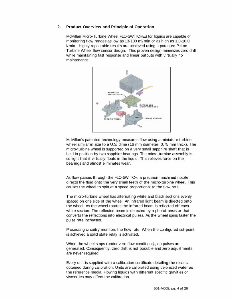
2. Product Overview and Principle of Operation McMillan Micro-Turbine Wheel FLO-SWITCHES for liquids are capable of monitoring flow ranges as low as 13-100 ml/min or as high as 1.0-10.0 l/min. Highly repeatable results are achieved using a patented Pelton Turbine Wheel flow sensor design. This proven design minimizes zero drift while maintaining fast response and linear outputs with virtually no maintenance.
McMillan’s patented technology measures flow using a miniature turbine wheel similar in size to a U.S. dime (16 mm diameter, 0.75 mm thick). The micro-turbine wheel is supported on a very small sapphire shaft that is held in position by two sapphire bearings. The micro-turbine assembly is so light that it virtually floats in the liquid. This relieves force on the bearings and almost eliminates wear. As flow passes through the FLO-SWITCH, a precision machined nozzle directs the fluid onto the very small teeth of the micro-turbine wheel. This causes the wheel to spin at a speed proportional to the flow rate. The micro-turbine wheel has alternating white and black sections evenly spaced on one side of the wheel. An infrared light beam is directed onto the wheel. As the wheel rotates the infrared beam is reflected off each white section. The reflected beam is detected by a phototransistor that converts the reflections into electrical pulses. As the wheel spins faster the pulse rate increases. Processing circuitry monitors the flow rate. When the configured set-point is achieved a solid state relay is activated. When the wheel stops (under zero flow conditions), no pulses are generated. Consequently, zero drift is not possible and zero adjustments are never required. Every unit is supplied with a calibration certificate detailing the results obtained during calibration. Units are calibrated using deionized water as the reference media. Flowing liquids with different specific gravities or viscosities may effect the calibration.
501-M005, pg. 5 of 26
3. Non-Standard Products (Z Suffixes) Please note that the installation instructions, operating instructions, and specifications included within this manual apply to standard production models only. If your FLO-SWITCH has a “Z” suffix (e.g. 501-Z0123) then your unit is non-standard. Contact the factory to check if the installation, operation, or specifications of your flow switch are different than detailed in this manual.
B. Installation
CAUTION: DO NOT FLOW ANY GAS THROUGH A LIQUID FLO-SWITCH. THIS WILL DAMAGE THE MICRO-TURBINE ASSEMBLY AND VOID THE WARRANTY.
CAUTION: Do not exceed the pressure, temperature or power operating ranges detailed in the SPECIFICATIONS section of this manual. McMillan Company shall not be liable for any damage or injury caused by incorrect operation of their products.
1. General Considerations
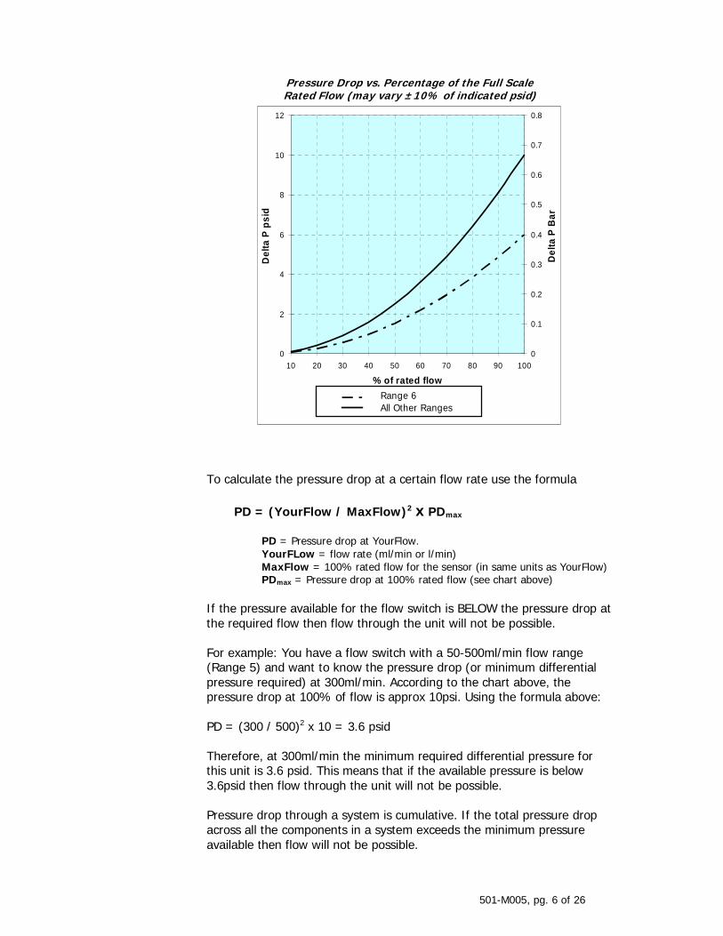
It is recommended that a safety shut-off valve be installed upstream of (before) the FLO-SWITCH. All wetted parts should be checked for compatibility with the liquid to be used. If there are any incompatibilities e.g. highly corrosive liquid, then the unit may be damaged or fail prematurely. Such damage will not be repaired under warranty. Units should be installed in a clean, dry environment with an ambient temperature that is as stable as possible. Avoid areas with strong magnetic fields, strong air flows or excessive vibration. If the liquid to be used may contain particles larger than 25 microns then a filter (25 microns or less) should be installed upstream of (before) the unit. The required differential press (or pressure drop across the unit) decreases exponentially with decreases in flow rate.
501-M005, pg. 6 of 26
Pressure Drop vs. Percentage of the Full Scale Rated Flow (may vary ±10% of indicated psid)
0
2
4
6
8
10
12
10 20 30 40 50 60 70 80 90 100
% of rated flow
Del
ta P
psi
d
0
0.1
0.2
0.3
0.4
0.5
0.6
0.7
0.8
Del
ta P
Bar
Range 6All Other Ranges
To calculate the pressure drop at a certain flow rate use the formula
PD = (YourFlow / MaxFlow)2 x PDmax
PD = Pressure drop at YourFlow. YourFLow = flow rate (ml/min or l/min) MaxFlow = 100% rated flow for the sensor (in same units as YourFlow) PDmax = Pressure drop at 100% rated flow (see chart above)
If the pressure available for the flow switch is BELOW the pressure drop at the required flow then flow through the unit will not be possible. For example: You have a flow switch with a 50-500ml/min flow range (Range 5) and want to know the pressure drop (or minimum differential pressure required) at 300ml/min. According to the chart above, the pressure drop at 100% of flow is approx 10psi. Using the formula above: PD = (300 / 500)2 x 10 = 3.6 psid Therefore, at 300ml/min the minimum required differential pressure for this unit is 3.6 psid. This means that if the available pressure is below 3.6psid then flow through the unit will not be possible. Pressure drop through a system is cumulative. If the total pressure drop across all the components in a system exceeds the minimum pressure available then flow will not be possible.
501-M005, pg. 7 of 26
For example: A system has a pressure of 30-40psi. There are several components and the sum of their pressure drops at the required flow rate is 32psid. If the system is operating at 30psi, flow would not be possible as the total of the pressure drops would be greater than the pressure available. The system will only operate if the system pressure is above 32psi. If there is any possibility that there may be bubbles or entrapped gas in the system then the outlet tubing should be elevated above the inlet port. This will enable any gas that may become entrapped in the unit to escape.
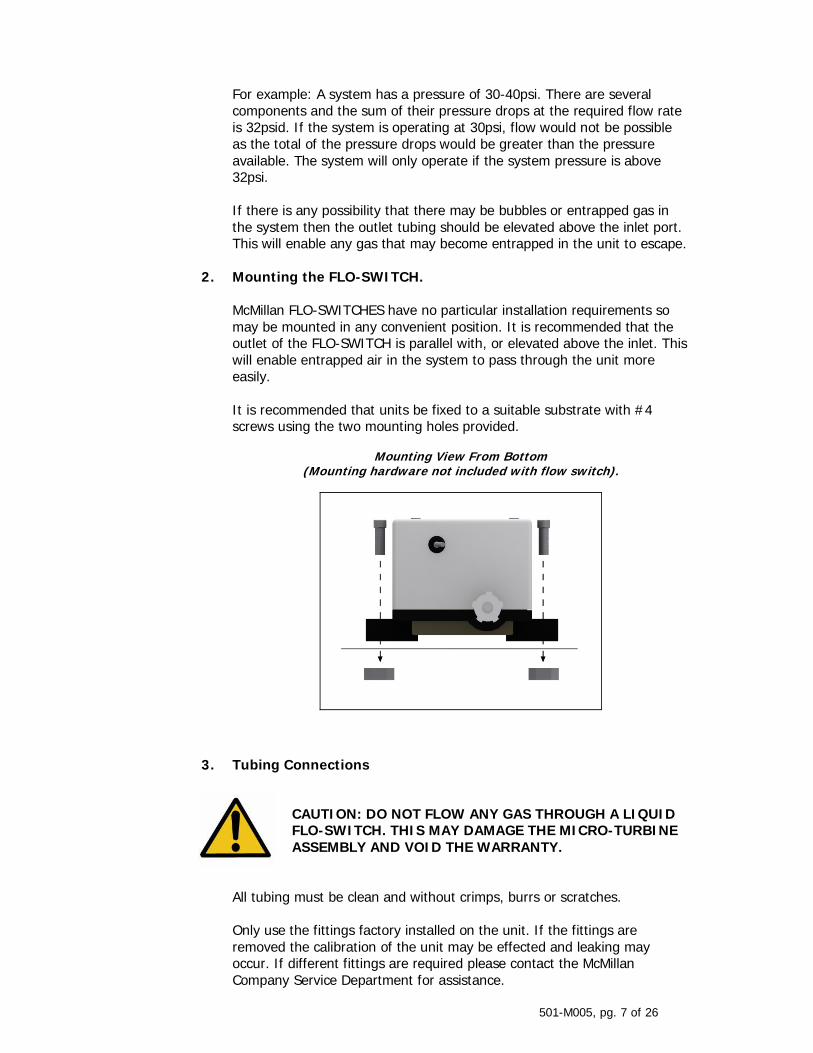
2. Mounting the FLO-SWITCH. McMillan FLO-SWITCHES have no particular installation requirements so may be mounted in any convenient position. It is recommended that the outlet of the FLO-SWITCH is parallel with, or elevated above the inlet. This will enable entrapped air in the system to pass through the unit more easily. It is recommended that units be fixed to a suitable substrate with #4 screws using the two mounting holes provided.
Mounting View From Bottom (Mounting hardware not included with flow switch).
3. Tubing Connections
CAUTION: DO NOT FLOW ANY GAS THROUGH A LIQUID FLO-SWITCH. THIS MAY DAMAGE THE MICRO-TURBINE ASSEMBLY AND VOID THE WARRANTY.
All tubing must be clean and without crimps, burrs or scratches. Only use the fittings factory installed on the unit. If the fittings are removed the calibration of the unit may be effected and leaking may occur. If different fittings are required please contact the McMillan Company Service Department for assistance.
501-M005, pg. 8 of 26
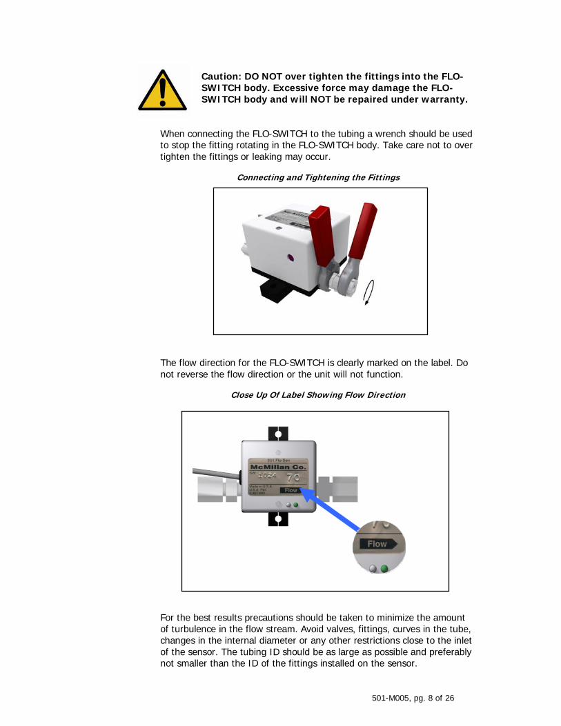
Caution: DO NOT over tighten the fittings into the FLO-SWITCH body. Excessive force may damage the FLO-SWITCH body and will NOT be repaired under warranty.
When connecting the FLO-SWITCH to the tubing a wrench should be used to stop the fitting rotating in the FLO-SWITCH body. Take care not to over tighten the fittings or leaking may occur.
Connecting and Tightening the Fittings
The flow direction for the FLO-SWITCH is clearly marked on the label. Do not reverse the flow direction or the unit will not function.
Close Up Of Label Showing Flow Direction
For the best results precautions should be taken to minimize the amount of turbulence in the flow stream. Avoid valves, fittings, curves in the tube, changes in the internal diameter or any other restrictions close to the inlet of the sensor. The tubing ID should be as large as possible and preferably not smaller than the ID of the fittings installed on the sensor.
501-M005, pg. 9 of 26
For 0.3-2.0 L/min (Range 7) units a 10 cm straight length of tube before the sensor is recommended. For higher flow range units (0.6-5.0 L/min and 1.1-10.0 L/min), a 20 cm straight length of tubing before the sensor is recommended. If this is not possible it is recommended that straight lengths between all connections on the inlet side of the sensor are as long as possible and 90 degree fittings (with a large enough ID) are used instead of curves in the tubing.
4. Electrical Connections
Caution: Incorrect wiring may cause severe damage to the unit. Applying an AC voltage (115VAC or 230VAC) directly to the unit will cause damage. Read the following instructions carefully before making any connections.
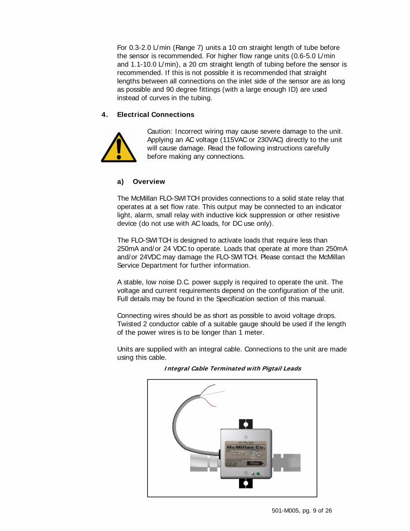
a) Overview The McMillan FLO-SWITCH provides connections to a solid state relay that operates at a set flow rate. This output may be connected to an indicator light, alarm, small relay with inductive kick suppression or other resistive device (do not use with AC loads, for DC use only). The FLO-SWITCH is designed to activate loads that require less than 250mA and/or 24 VDC to operate. Loads that operate at more than 250mA and/or 24VDC may damage the FLO-SWITCH. Please contact the McMillan Service Department for further information. A stable, low noise D.C. power supply is required to operate the unit. The voltage and current requirements depend on the configuration of the unit. Full details may be found in the Specification section of this manual. Connecting wires should be as short as possible to avoid voltage drops. Twisted 2 conductor cable of a suitable gauge should be used if the length of the power wires is to be longer than 1 meter. Units are supplied with an integral cable. Connections to the unit are made using this cable.
Integral Cable Terminated with Pigtail Leads
501-M005, pg. 10 of 26
b) Connecting to the FLO-SWITCH
Caution: Avoid high voltage static discharges to any of the wires. Do not connect the relay output wire to a voltage without a suitable load or allow it to contact the power wires at any time. DAMAGE WILL RESULT!
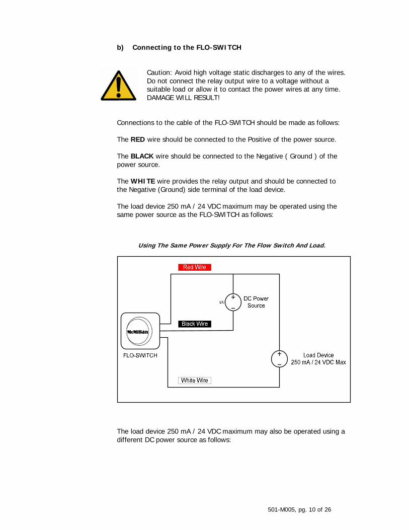
Connections to the cable of the FLO-SWITCH should be made as follows: The RED wire should be connected to the Positive of the power source. The BLACK wire should be connected to the Negative ( Ground ) of the power source. The WHITE wire provides the relay output and should be connected to the Negative (Ground) side terminal of the load device. The load device 250 mA / 24 VDC maximum may be operated using the same power source as the FLO-SWITCH as follows:
Using The Same Power Supply For The Flow Switch And Load.
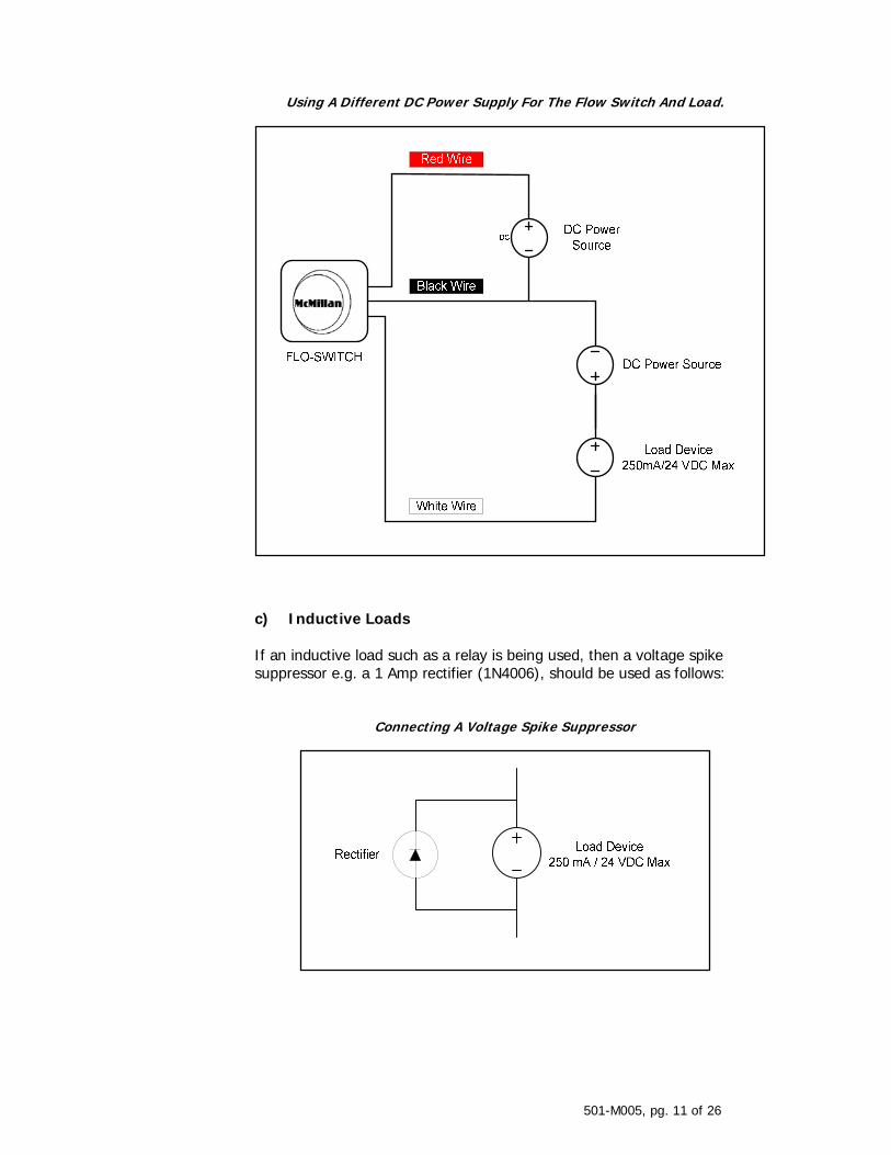
The load device 250 mA / 24 VDC maximum may also be operated using a different DC power source as follows:
501-M005, pg. 11 of 26
Using A Different DC Power Supply For The Flow Switch And Load.
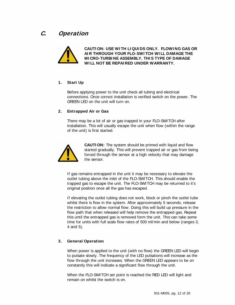
c) Inductive Loads If an inductive load such as a relay is being used, then a voltage spike suppressor e.g. a 1 Amp rectifier (1N4006), should be used as follows:
Connecting A Voltage Spike Suppressor
501-M005, pg. 12 of 26
C. Operation
CAUTION: USE WITH LIQUIDS ONLY. FLOWING GAS OR AIR THROUGH YOUR FLO-SWITCH WILL DAMAGE THE MICRO-TURBINE ASSEMBLY. THIS TYPE OF DAMAGE WILL NOT BE REPAIRED UNDER WARRANTY.
1. Start Up
Before applying power to the unit check all tubing and electrical connections. Once correct installation is verified switch on the power. The GREEN LED on the unit will turn on.
2. Entrapped Air or Gas There may be a lot of air or gas trapped in your FLO-SWITCH after installation. This will usually escape the unit when flow (within the range of the unit) is first started.
CAUTION: The system should be primed with liquid and flow started gradually. This will prevent trapped air or gas from being forced through the sensor at a high velocity that may damage the sensor.
If gas remains entrapped in the unit it may be necessary to elevate the outlet tubing above the inlet of the FLO-SWITCH. This should enable the trapped gas to escape the unit. The FLO-SWITCH may be returned to it’s original position once all the gas has escaped. If elevating the outlet tubing does not work, block or pinch the outlet tube whilst there is flow in the system. After approximately 5 seconds, release the restriction to allow normal flow. Doing this will build up pressure in the flow path that when released will help remove the entrapped gas. Repeat this until the entrapped gas is removed form the unit. This can take some time for units with full scale flow rates of 500 ml/min and below (ranges 3, 4 and 5).
3. General Operation When power is applied to the unit (with no flow) the GREEN LED will begin to pulsate slowly. The frequency of the LED pulsations will increase as the flow through the unit increases. When the GREEN LED appears to be on constantly this will indicate a significant flow through the unit. When the FLO-SWITCH set point is reached the RED LED will light and remain on whilst the switch is on.
501-M005, pg. 13 of 26
For NORMALLY OPEN (“NO”) operation the switch will be open from no flow up to the set point and will close when the flow reaches or exceeds the set point. For NORMALLY CLOSED (“NC”) operation the switch will be closed from no flow up to the set point and will open when the flow reaches or exceeds the set point.
4. Verifying the Set Point An indication of the approximate set point may be obtained by examining the position of the set point potentiometer on the side of the FLO-SWITCH.
Determining The Approximate Set Point
Potentiometer Position
Set Point Proportion of Max Rated
Flow
“Clock Position”
100% 8 o’clock
50% 1 o’clock
10% 4 o’clock
For example: A unit with a flow range of 50-500 ml/min has the set point potentiometer in approximately the 1 o’clock position. From the table above this equates to approximately 50% of the full scale rated flow. This would be equivalent to a set point of approximately 250 ml/min. The FLO-SWITCH set point may be more accurately verified using empirical methods. It should be noted that the use of empirical methods outside a certified calibration laboratory is subject to inaccuracy and error. These methods should only be used to gain an indication of a FLO-SWITCH’s performance. Please contact the McMillan Service Department if accurate, certified recalibration is required. A typical empirical set point calibration check may be carried out as follows: Carefully adjust the flow rate in the system to the point that the RED LED becomes lit. With the flow rate constant, liquid flowing through the unit
501-M005, pg. 14 of 26
should be gathered in a container over a timed interval. The total volume flowed over the timed period should then be measured using a measuring cylinder. The actual flow rate (in the same units as the flow switch calibration certificate) may then be calculated. The actual flow rate should then be compared to the specified flow rate set point to determine the error in calibration. For example:
For a unit with a flow range of 30-200ml/min and set point of 70ml/min: With a constant flow the actual volume measured over 30 seconds was 36ml. Therefore the actual flow rate is: (36 / 30) x 60 = 72ml/min The error is therefore 72 – 70 = 2ml/min or 2.9%
5. Adjusting the Set Point Adjustments to the FLO-SWITCH set point may be made by turning the trim potentiometer on the side of the unit next to the cable exit point. Using an empirical method (see section 4 above) or reference flow sensor adjust the flow rate through the switch to the required amount for activation of the relay. With the flow rate constant, carefully adjust the trim potentiometer to the point where the RED LED is just activated. The FLO-SWITCH is now set to the required set point.
Set Point Adjustment Potentiometer
If the unit cannot be suitably adjusted please contact the McMillan Service Department.
501-M005, pg. 15 of 26
6. Operating at Flow Rates Outside the Calibrated Flow Range
CAUTION:. If the flow through the unit exceeds 120% of the maximum rated (full scale) flow the unit may be damaged. This type of damage will not be repaired under warranty.
The FLO-SWITCH is only accurate within the calibrated flow range for the unit. This is detailed on the calibration certificate. The unit will still operate, to some degree, outside this flow range. Results obtained when operating outside the specified range of the unit are not accurate but may be considered repeatable. If the flow rate is above the maximum rated (or full scale) flow, the unit will still operate but the set point may only be adjusted up to 100% of the maximum rated flow. Flows must not exceed 120% of the maximum rated flow or the unit may be damaged.
7. Zero Adjustments It is impossible for there to be any zero drift so zero adjustments are never required.
8. Recalibration Please contact the McMillan Service Department if recalibration is required.
9. Calibrating FLO-SWITCHES for Different Liquids McMillan FLO-SWITCHES will operate with most translucent liquids subject to compatibility of the wetted parts. Best results are obtained with low viscosity (less than 10 centistokes) liquids. For information regarding higher viscosity liquids, contact the McMillan Service Department. Units are calibrated with deionized water as the reference media. Using other liquids will effect the calibration. The amount of calibration error will depend on the characteristics of the liquid being flowed. The error in the set point (or calibration) should be calculated and utilized as detailed in section 3 above. The set point may be adjusted using the required liquid as detailed in section 5 above.
501-M005, pg. 16 of 26
D. Maintenance and Product Care 1. General
CAUTION: Do not disassemble your FLO-SWITCH for any reason. If the unit appears to be malfunctioning please contact the McMillan Service Department.
McMillan FLO-SWITCHES require no periodic maintenance if used within the recommended specifications. Inlet filters should be periodically checked and cleaned / replaced as necessary. Regularly check all electrical and process connections for damage or deterioration. If the FLO-SWITCH is to be stored, keep both the inlet and outlet ports sealed. Do not store a FLO-SWITCH with any chemical other than water (or air) inside it over an extended period of time. Prolonged exposure to chemicals other than water may lead to precipitation or corrosion.
2. Cleaning and Flushing If there is a build up of deposits or residues from the measured chemicals it may be necessary to clean or flush the unit. This should be done by flowing clean, particle free water through the unit at a flow rate, pressure and temperature within the specifications of the unit. If necessary, flow may be reversed to assist flushing. Under no circumstances should gas or air be flowed through the unit. This will cause severe damage.
3. Returning Units for Repair or Recalibration To return a unit for repair or recalibration please contact the McMillan Service Department or follow the procedure detailed on the McMillan web site. A Return to Manufacturer Authorization (RMA) number will then be issued to enable the unit to be returned. Please note that no returns will be accepted unless the RMA number is clearly indicated on the outside of all packages. Once the unit has been received it will be evaluated and the cost of any repairs / recalibration determined. Once agreement has been received to pay for all the necessary work the unit will be processed and returned. No charges will be made for Warranty Repairs (see section H). The McMillan Service Department may be contacted as follows:
501-M005, pg. 17 of 26
Mailing address: McMillan Company P.O. Box 1340 Georgetown, TX 78627 U.S.A. Phone: U.S.A. (512) 863-0231 Fax: U.S.A. (512) 863-0671
Email: [email protected] Website: www.mcmflow.com
501-M005, pg. 18 of 26
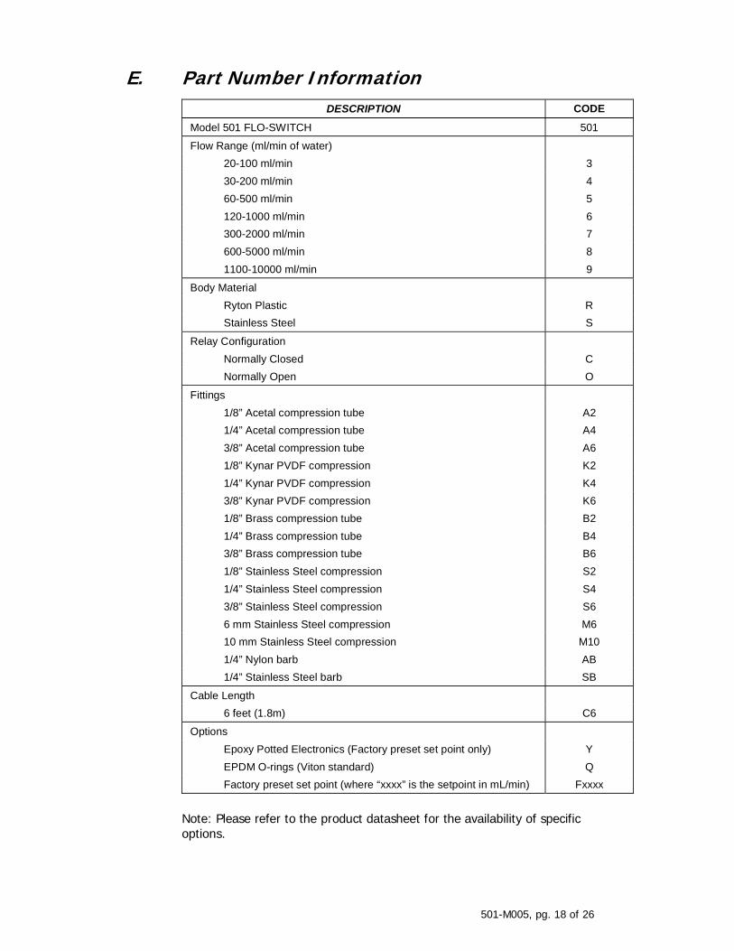
E. Part Number Information
DESCRIPTION CODE
Model 501 FLO-SWITCH 501
Flow Range (ml/min of water) 20-100 ml/min 3 30-200 ml/min 4 60-500 ml/min 5 120-1000 ml/min 6 300-2000 ml/min 7 600-5000 ml/min 8 1100-10000 ml/min 9
Body Material Ryton Plastic R Stainless Steel S
Relay Configuration Normally Closed C Normally Open O
Fittings 1/8” Acetal compression tube A2 1/4” Acetal compression tube A4 3/8” Acetal compression tube A6 1/8” Kynar PVDF compression K2 1/4” Kynar PVDF compression K4 3/8” Kynar PVDF compression K6 1/8” Brass compression tube B2 1/4” Brass compression tube B4 3/8” Brass compression tube B6 1/8” Stainless Steel compression S2 1/4” Stainless Steel compression S4 3/8” Stainless Steel compression S6 6 mm Stainless Steel compression M6 10 mm Stainless Steel compression M10 1/4” Nylon barb AB 1/4” Stainless Steel barb SB
Cable Length 6 feet (1.8m) C6
Options Epoxy Potted Electronics (Factory preset set point only) Y EPDM O-rings (Viton standard) Q Factory preset set point (where “xxxx” is the setpoint in mL/min) Fxxxx
Note: Please refer to the product datasheet for the availability of specific options.
501-M005, pg. 19 of 26
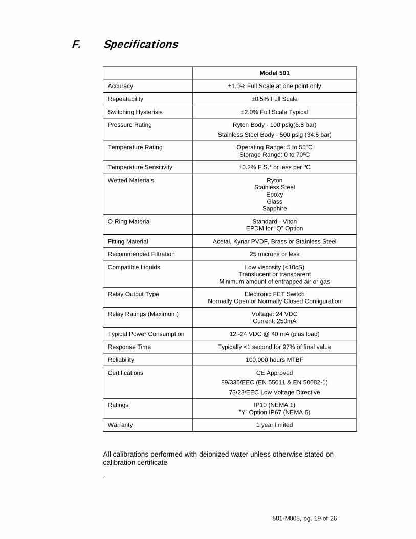
F. Specifications
Model 501
Accuracy ±1.0% Full Scale at one point only
Repeatability ±0.5% Full Scale
Switching Hysterisis ±2.0% Full Scale Typical
Pressure Rating Ryton Body - 100 psig(6.8 bar) Stainless Steel Body - 500 psig (34.5 bar)
Temperature Rating Operating Range: 5 to 55ºC Storage Range: 0 to 70ºC
Temperature Sensitivity ±0.2% F.S.* or less per ºC
Wetted Materials Ryton Stainless Steel
Epoxy Glass
Sapphire
O-Ring Material Standard - Viton EPDM for “Q” Option
Fitting Material Acetal, Kynar PVDF, Brass or Stainless Steel
Recommended Filtration 25 microns or less
Compatible Liquids Low viscosity (<10cS) Translucent or transparent
Minimum amount of entrapped air or gas
Relay Output Type Electronic FET Switch Normally Open or Normally Closed Configuration
Relay Ratings (Maximum) Voltage: 24 VDC Current: 250mA
Typical Power Consumption 12 -24 VDC @ 40 mA (plus load)
Response Time Typically <1 second for 97% of final value
Reliability 100,000 hours MTBF
Certifications CE Approved 89/336/EEC (EN 55011 & EN 50082-1)
73/23/EEC Low Voltage Directive
Ratings IP10 (NEMA 1) ”Y” Option IP67 (NEMA 6)
Warranty 1 year limited
All calibrations performed with deionized water unless otherwise stated on calibration certificate
.
501-M005, pg. 20 of 26
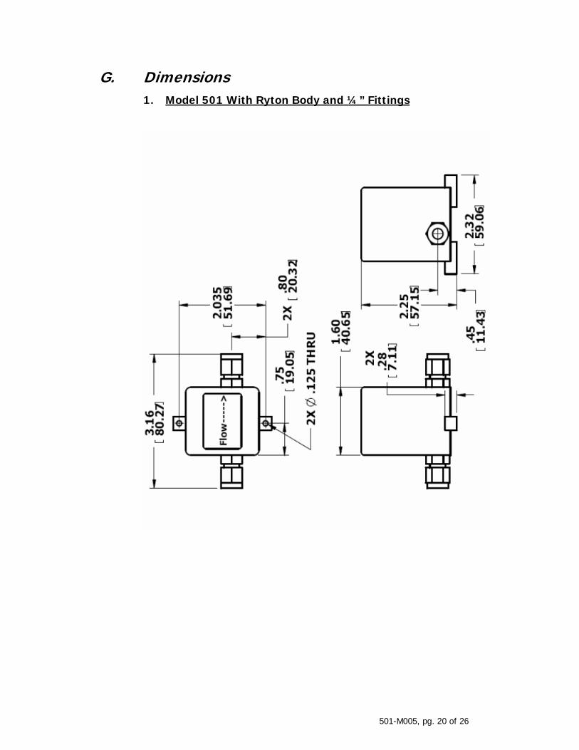
G. Dimensions
1. Model 501 With Ryton Body and ¼” Fittings
501-M005, pg. 21 of 26
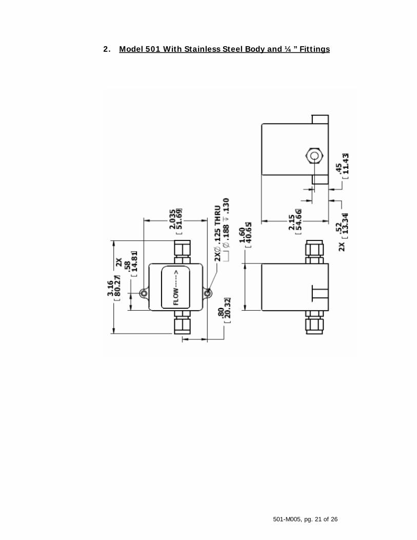
2. Model 501 With Stainless Steel Body and ¼” Fittings
501-M005, pg. 22 of 26
H. Limited Warranty For Gas and Liquid Micro-Turbine Flow Products and Associated Standard Accessories (Excludes Ultra High Purity Products) DURATION OF LIMITED WARRANTY, MATERIALS & WORKMANSHIP
R.D. McMillan Co., Inc., hereinafter referred to as “McMillan”, warrants these products and their associated standard accessories manufactured by McMillan and supplied hereunder, to be free from defects in materials and workmanship for a period of twelve (12) months from the date of shipment to the customer when installed, serviced and operated in its recommended environment. This warranty is not affected in any part by McMillan providing technical support or advice.
Replacement parts are warranted to be free from defects in material or workmanship for ninety (90) days or for the remainder of the Limited Warranty period of the McMillan product in which they are installed, whichever is longer. Parts not installed by factory authorized service centers may void the warranty.
PRODUCT RETURNS
(a) General Policy: Any product or parts determined by McMillan’s inspection to have failed per this warranty, will at McMillan’s option, be repaired or replaced with an equivalent or comparable product without charge. McMillan’s obligation hereunder shall be limited to such repair and/or replacement and shall be conditional upon McMillan’s receiving written notice of any alleged defect within ten (10) days of its discovery. The customer will, however, be responsible for returning the product to McMillan’s manufacturing facility in Georgetown, Texas, U.S.A., and for assuming the cost of removing the original product and reinstalling the repaired or replaced product. A written specific explanation of the problem must be included with each returned product. Returned goods should be properly packaged to prevent shipping damage and shipped prepaid to McMillan.
(b) Safety Requirements: For safety reasons, McMillan must be advised of any hazardous fluid or toxic materials that were in or on the product to be returned. Customer must certify in writing that all such hazardous, corrosive or toxic substances have been completely removed, cleaned or neutralized from the returned product prior to shipment to McMillan. McMillan shall hold the returned items pending receipt of customer’s statement for defect and certification of cleanliness of returned items, provided that, prior to such receipt, risk of loss of returned items shall remain with customer. Flow sensors, flow meters and flow controllers must be thoroughly cleaned to remove any toxic, corrosive or hazardous fluids that may internally remain therein before shipping product to McMillan.
(c) Shipping Requirements: Customer is responsible for all shipping charges (except for those products under warranty, in which cases customer shall bear the cost of inbound shipping as described herein below, and McMillan shall bear the cost of outbound shipping). Customer is responsible for the costs of out of warranty repairs and/or recalibration. McMillan will ship items repaired under warranty back to customer by the most economical shipping means. Expedited shipping methods may be available at customer’s expense. All returned items shall be returned to a McMillan authorized service center., freight prepaid, accompanied or preceded by a particularized statement of the claimed defect and with a clearly readable Returned Material Authorization (“RMA”) number affixed to the shipping label. Contact McMillan Customer Service Department for RMA number. Warranty claims shall be made only by using the McMillan’s Returned Material Authorization form, completely filled out and returned to McMillan in accord with McMillan’s Product Return Policy and Procedure Form.
501-M005, pg. 23 of 26
Contact McMillan’s Customer Service Department as follows for instructions:
Telephone calls in U.S.A. ( CST ) 1-800-861-0231 Outside U.S.A. +1 512-863-0231 Or Fax: + 1-512-863-0671
E-mail: [email protected]
DESIGN, PROCESS and MANUFACTURING CHANGES
McMillan may make changes in the design or manufacture of any products sold hereunder without incurring any obligation to incorporate such changes into products manufactured prior to incorporation of such design or manufacturing changes. McMillan reserves the right to make design or manufacturing changes without prior notice. McMillan products and replacement parts are manufactured using new materials or new and equivalent to new in appearance, performance and reliability. Due to continuous research, testing, product improvements and enhancements, McMillan reserves the right to change product specifications without notice, except to the extent an outstanding bid obligation exists.
LIMITATION of LIABILITY
Except as expressly set forth in this limited warranty, McMillan makes no other warranties or conditions, express or implied, including any implied warranties of merchantability and fitness for a particular purpose. McMillan expressly disclaims all warranties and conditions not stated in this limited warranty. Any implied warranties that may be imposed by law are limited in duration to the limited warranty period. Buyer/customer agrees that models or samples shown to buyer/customer were merely used to illustrate the purchased product and not to represent, promise or guarantee that any purchased products delivered hereunder would conform to such models or samples. McMillan’s distributors or sales representatives have no authority to give warranties beyond those provided in this limited warranty.
If customer’s product fails to work as warranted herein, customer’s sole and exclusive remedy shall be the repair or replacement at McMillan’s option. McMillan is not liable for any damages caused by the product or the failure of the product to perform, including any lost profits or savings, incidental or consequential damages. McMillan is not liable for any claim made by a third party or made by a buyer for a third party. No actions arising out of sale of the products sold hereunder or this limited warranty may be brought by either party more than two (2) years after the cause of action accrues. This limitation of liability applies whether damages are sought, or a claim made, under this limited warranty or as a tort claim (including negligence and strict product liability), a contract claim, or any other claim. This limitation of liability cannot be waived or amended by any person. This limitation of liability will be effective even if customer has advised McMillan or an authorized representative or distributor of McMillan of the possibility of any such damages This limited warranty gives customer specific legal rights. Customer may also have other rights that may vary from state to state or country to country. Customer is hereby advised to consult applicable state or country laws for a full determination of customer’s rights. EXCLUSIONS FROM WARRANTY
This limited warranty provided herein shall not apply to any product which:
(1) has been repaired or altered outside of McMillan’s factory (or authorized service center) in any way so as, in McMillan’s judgment, to affect such purchased item’s reliability or performance.
(2) has been subject to misuse, mishandling, negligence, accident, or acts of God. (3) has been operated other than in accordance with the printed instructions prepared
by McMillan and provided by McMillan with the product. (4) has been returned to McMillan after more than thirty (30) days following the date of
the alleged product failure. (5) has been returned to McMillan without complying with the Safety Requirements or
the Shipping Requirements contained herein. (6) requires calibration and/or routine maintenance, unless this calibration or routine
maintenance is required as a result of a product failure that is covered under terms of this warranty.
501-M005, pg. 24 of 26
(7) are consumable parts, such as filter elements, batteries or tube fittings. (8) requires replacement or repairs resulting from buyer’s improper choice of product
flow range, or require repair or replacement due to buyer subjecting product to corrosive fluids or other fluids not suited for use in product
(9) has flow passages clogged due to failure to use a filter to protect product from particulates in fluid flow stream, or other cause to produce clogged passages
(10) has been operated outside of recommended specifications (such as voltage, temperature, or flow range, etc.)
(11) has been damaged or cracked due to negligence in failing to follow printed instructions to prevent excessive torque from being applied to product housing ( generally polyphenylene sulfide plastic )
(12) has been damaged as a result of gross over-speeding, or prolonged over-speeding of the micro-turbine wheel
(13) has been damaged as a result of severe sudden impact forces (example: dropping the product)
METHOD OF SETTLEMENT OF ANY CLAIMS, DISPUTES AND CONTROVERSIES
The provisions of this warranty are severable and if one or more provisions are deemed invalid, the remaining provisions shall remain in effect. Further, in the event that any provision is held to be over broad as written, such provision shall be deemed amended to narrow its application to the extent necessary to make the provision enforceable according to applicable law and shall be enforced as amended. This warranty shall be construed and interpreted in English.
All claims, disputes and controversies arising out of or relating in any way to claims under any warranties, either express or implied (including implied warranty of merchantability), or claims based on any consumer protection act or deceptive trade practice act, contract, tort, statute, or common law, or any alleged breach, default, and/or misrepresentation, will be resolved by means of final and binding arbitration. This limited warranty, including any contests to the validity or enforceability of this limited warranty, shall be finally settled by arbitration under the Rules of Conciliation and Arbitration of the International Chamber of Commerce by one or more of its arbitrators appointed in accordance with the Rules, and judgment upon award rendered may be entered in any court having jurisdiction thereof. The place of arbitration shall be Austin, Texas U.S.A., and the Texas Uniform Commercial Code, as then enacted shall govern the rights and duties of the parties of this agreement without regard to conflicts-of-law principles. The arbitration shall be conducted in English. The UN Convention on Contracts for the International Sale of Goods shall not apply to this Limited Warranty.
R. D. McMillan Company, Inc. 7075 R.R. 2338 P. O. Box 1340 Georgetown, Texas U.S.A. 78627
501-M005, pg. 25 of 26
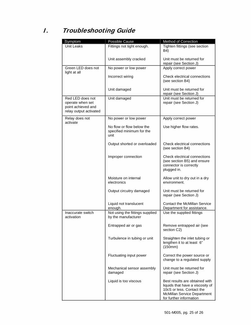
I. Troubleshooting Guide
Symptom Possible Cause Method of Correction Unit Leaks Fittings not tight enough.
Unit assembly cracked
Tighten fittings (see section B4) Unit must be returned for repair (see Section J)
Green LED does not light at all
No power or low power Incorrect wiring Unit damaged
Apply correct power Check electrical connections (see section B4) Unit must be returned for repair (see Section J)
Red LED does not operate when set point achieved and relay output activated
Unit damaged Unit must be returned for repair (see Section J)
Relay does not activate
No power or low power No flow or flow below the specified minimum for the unit Output shorted or overloaded Improper connection Moisture on internal electronics Output circuitry damaged Liquid not translucent enough.
Apply correct power Use higher flow rates. Check electrical connections (see section B4) Check electrical connections (see section B5) and ensure connector is correctly plugged in. Allow unit to dry out in a dry environment. Unit must be returned for repair (see Section J) Contact the McMillan Service Department for assistance.
Inaccurate switch activation
Not using the fittings supplied by the manufacturer Entrapped air or gas Turbulence in tubing or unit Fluctuating input power Mechanical sensor assembly damaged Liquid is too viscous
Use the supplied fittings Remove entrapped air (see section C2) Straighten the inlet tubing or lengthen it to at least 6” (150mm) Correct the power source or change to a regulated supply Unit must be returned for repair (see Section J) Best results are obtained with liquids that have a viscosity of 10cS or less. Contact the McMillan Service Department for further information
501-M005, pg. 26 of 26
J. Contacting McMillan Website: www.mcmflow.com Email: [email protected] Mailing address: McMillan Company
P.O. Box 1340 Georgetown, TX 78627 U.S.A. Shipping address: McMillan Company
7075 RR 2338 Georgetown, TX 78628 U.S.A. Phone: (512) 863-0231 Fax: (512) 863-0671 For repairs and/or return information, please contact our service department any of the ways shown above. Goods must not be shipped to McMillan without authorization (see section D3).