Embed Size (px)
Citation preview

Machine Tools
Installation Manual (Lynx 220M/LM)


1
Lynx 220M/LM L220MISE95
Table of Contents
1. Preparations before shipment .................................................................................. 2
1.1 Installation Site................................................................................................................. 2
1.2 Foundation Work .............................................................................................................. 6
2. Transportation ........................................................................................................... 8
3. Packlist ..................................................................................................................... 10
4. Removing the transit clamps and cleansing the machine ................................... 12
4.1 Removing the transit clamps .......................................................................................... 12
4.2 Cleansing the machine................................................................................................... 13
5. Checking and fueling the oil tanks......................................................................... 14
5.1 Oil Tank .......................................................................................................................... 14
5.2 Lub. Tank ....................................................................................................................... 14
6. Main Power Source.................................................................................................. 15
7. Power On .................................................................................................................. 16
7.1 Power On ....................................................................................................................... 16
7.2 Checking the pressure on each unit ............................................................................... 16
8. Machine Leveling ..................................................................................................... 18
9. Machine Precision ................................................................................................... 20
9.1 Parallelism between center line of spindle and Z-axis movement ................................... 20
9.2 Concentricity between center line of the spindle and tail stock ....................................... 22
9.3 Precision on the tool post ............................................................................................... 24
10. Reference Point & Correction ............................................................................... 26
11. Q-Setter Operation ................................................................................................. 28
12. Installing the coolant tank .................................................................................... 30

2
Lynx 220M/LM L220MISE95
1. Preparations before shipment
1.1 Installation Site
1) In a place of weak ground, a solid foundation should be made so that no sinking and
tilting should ever happen even after the installation.
2) Keep the machine as far as possible from vibration source such as road,
stamping/pressing device or planner. If it's inevitable, make holes around the foundation
ground to reduce the impact from the vibration.
3) Keep the machine away from high-frequency device, electric discharge machine or
electric welding machine; do not share the power source with any of these machines.
Otherwise, it may cause a failure of the NC device.
4) The ideal operation condition is between 40% and 75% in humidity at 20ºC.
5) To keep the static accuracy of the machine below the compensation level, install the
machine in a place of less or zero impact from the air flow on site. The air temperature
is not a required condition. However, an optimal air temperature around the machine is
between 17ºC and 25ºC.
6) To keep the static accuracy of the machine around the compensation level, the daily
temperature difference should be ±2ºC for one day (24 hours) and the temperature
difference at 5m from the bottom should be within 1ºC.
Ref 1) Front View of Side Coolant Tank & Chip Conveyor
3
Lynx 220M/LM L220MISE95
Ref 2) Side View of Side Coolant Tank & Chip Conveyor※
Ref 3) Ground View of Side Coolant Tank & Chip Conveyor※

4
Lynx 220M/LM L220MISE95
Ref 4) Front View of Rear Coolant Tank & Chip Conveyor※
Ref ※ 5) Front View of Rear Coolant Tank & Chip Conveyor
5
Lynx 220M/LM L220MISE95
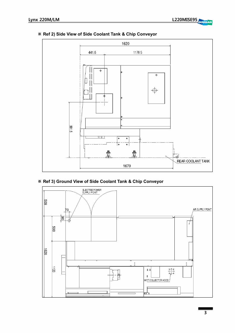
Ref 6) Ground View of Rear Coolant Tank & Chip Conveyor※

6
Lynx 220M/LM L220MISE95
1.2 Foundation Work
It is recommended to perform the foundation work for the machine accuracy.
If the following conditions are met, no foundation work is necessary in normal situations
or even a bolt is not necessary.
▪ The ground should be firm and strong.
▪ The concrete surface of the on-site floor should be at least 200mm thick.
▪ No gap is allowed between ground and concrete floor.
1) Foundation work timing and post checkpoints
It is recommended to take at least a two① -month schedule from completion of the
foundation work to completion of the installation.
It should take at least one month to cure the concreted surface.
After completion of the foundation work, measure each ch② eckpoint on the foundation
and take an appropriate action (mostly repair) if a problem is found.
2) Foundation work for installing the machine
Foundation Diagram ①
The below foundation diagram is a standard machine layout for reference. The actual
layout may differ depending on the machine. Refer to the layout diagram that is
specific to the machine to install.
Tolerance for each checkpoint※
Top View: ±10mm / Gap between holes: ±20mm
Cumulative gaps between holes : ±20mm / Size of foundation hole: ±10mm
7
Lynx 220M/LM L220MISE95
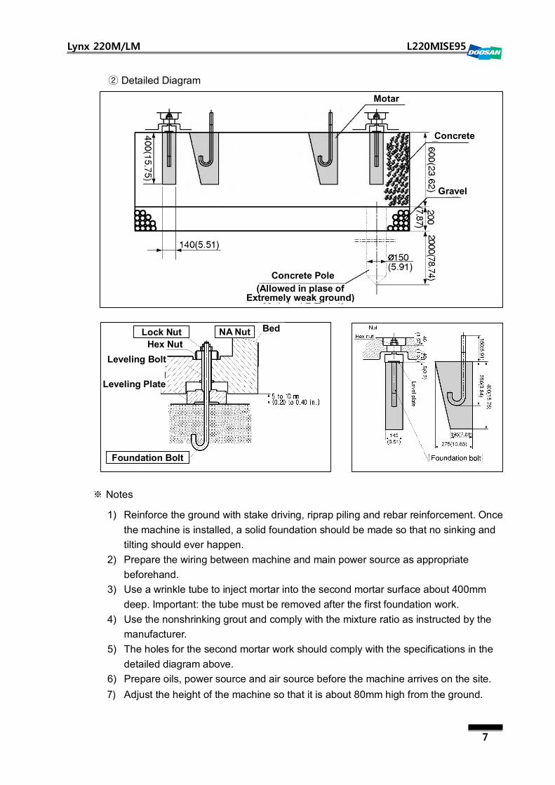
Detailed Diagram②
Notes※
1) Reinforce the ground with stake driving, riprap piling and rebar reinforcement. Once
the machine is installed, a solid foundation should be made so that no sinking and
tilting should ever happen.
2) Prepare the wiring between machine and main power source as appropriate
beforehand.
3) Use a wrinkle tube to inject mortar into the second mortar surface about 400mm
deep. Important: the tube must be removed after the first foundation work.
4) Use the nonshrinking grout and comply with the mixture ratio as instructed by the
manufacturer.
5) The holes for the second mortar work should comply with the specifications in the
detailed diagram above.
6) Prepare oils, power source and air source before the machine arrives on the site.
7) Adjust the height of the machine so that it is about 80mm high from the ground.
Motar
Concrete
Gravel
Concrete Pole
(Allowed in plase of Extremely weak ground)
Foundation Bolt
Bed NA Nut Lock Nut
Hex Nut
Leveling Bolt
Leveling Plate

8
Lynx 220M/LM L220MISE95
2. Transportation
Typically, the turning center system consists of 4 devices: body, electric cabinet, hydraulic
unit and turning center device.
Lynx220 series is a all-in-one system that you can transport without dismantling it into sub
assemblies.
However, the coolant tank is shipped separately by factory default.
(1) When the machine is delivered on site, check if every one of the units are all
included in the package based on the packing list.
(2) There are four ways to lift and transport the machine.
Using the crane①
Using the forklift②
Using the lifting hooks that are provided with the machine③
Using the roller to lift up the machine manually④
(3) In this process, take caution lest that the wire rope or shackles should impact on the
unit, and adjust the length of the rope as appropriate to prevent it from being
unbalanced.
(4) If the rope is short, it may cause an abrasion with brackets or covers. This is why you
must pay special attention to the rope length.

9
Lynx 220M/LM L220MISE95
1) Lifting instructions
(1) Return the saddle and tailstock to their respective reference point and fix the slide
and tail stock with the fixture.
(2) Remove tools and other materials outside of the machine.
(3) Turn off the machine and unplug the cable connectors.
(4) Remove the coolant tank from the machine.
(5) Connect the wire rope (for lifting) to the hook.
▪ Ensure that the wire rope is hooked firmly. Otherwise, the machine may fall off
during the lifting, causing a physical damage or even death.
Special care must be taken here.
(6) Use the crane to move the machine.
Precautions※
(1) Use only a rope of at least 20mm in the normal diameter.
(2) Adjust the angle formed by each wire line so that the ropes do not contact on the
machine body.
(The rope should not tilt beyond 40 degrees against the vertical line.)
(3) While lifting the machine, you must pay special attention to the balance.
(4) Place the machine down on the floor with much care.
(Lower the machine slowly on the floor lest that it should be impacted on the floor.)
Weight
Lynx 220 2,900Kg (Hydraulic Unit, Electric Cabinet, CNC included)
Lynx 220L 3,200Kg (Hydraulic Unit, Electric Cabinet, CNC included)
Lynx 220G 2,600Kg (Hydraulic Unit, Electric Cabinet, CNC included)
Lynx 220LM 4,000Kg (Hydraulic Unit, Electric Cabinet, CNC included)
Lynx 220M 3,600Kg (Hydraulic Unit, Electric Cabinet, CNC included)
2) Using the forklift
(1) Refer to the weight table above and select a forklift that supports an appropriate
load capacity.
(2) Close all front protective covers and doors.
(3) Insert the fork of the forklift into the lifting holes in the bottom of the machine base.
(4) Lift up the machine while keeping it balanced.
(5) Lower the machine slowly on the floor lest that it should be impacted on the floor.
3) Using the rolling
When rolling the machine to the installation site, take caution lest that it should crash on
the floor or be unbalanced.

10
Lynx 220M/LM L220MISE95
3. Packlist
Seq Picture Part No. Part Name Q'ty Specification
1 L21590827B KIT. BORING SLEEVE 1 L21590821
2 L21590837 KIT. DRILL SOCKET 1 ST L2159831
3 L21590847 KIT. U-DRILL SLEEVE 1 ST L21590841
4 L29311023E PLATE. LEVEL 5EA
5 L32580217D KIT. BORING SLEEVE 1 ST OD 25 MM
6 R80013C KIT. TOOL BOX 1 ST L31900021
7 R80050 GREASE GUN 1EA A-220
8 L29533124 PLUG. DUMMY 4EA BMT45P
9 S8010400 O-RING 4EA G40
10 R78881
R78842
SPANNER. HOOK
SPANNER. HEX
1EA
1EA
HS(25-28)
G22

11
Lynx 220M/LM L220MISE95
Seq Picture Part No. Part Name Q'ty Specification
11 R78845 KIT. PRECI-FLEX ADAP 1 ST 0.000.984-MM/ER20
12 R78843 KIT. MILLING COLLETS 1 ST ER20-MM(12PCS)
13 R70084 HANDLE. HEX. (BLACK) 2EA 1004-10HEX
14 R75570A JAW. SOFT 4 ST SB06B1(3PCS)
15 ELAMP0220 LAMP. HALOGEN 1EA H3 12V55W
16 S3520366 SCREW. SET 4EA BQ6X6

12
Lynx 220M/LM L220MISE95
4. Removing the transit clamps and cleansing the machine
4.1 Removing the transit clamps
Every axis of the machine is fixed with the applicable fixture before shipment for safety
purposes. When the machine settles down in the right position, remove all the fixtures.
※ Do NEVER operate the machine until the fixtures are all removed.
1) Z-axis fixture

13
Lynx 220M/LM L220MISE95
2) X-axis fixture
3) Q-setter fixture
4.2 Cleansing the machine
When removed all the transit clamps, wash off the rust preventive oil of the machine using
the light oil or cleaning oil. Then, apply lubricant for smoothing purposes. However, do
NEVER use chemicals or oils that can affect the coating of the machine, and keep the
machine away from any heating source during this process.

14
Lynx 220M/LM L220MISE95
5. Checking and fueling the oil tanks
You should supply sufficient oil to each tank before operating the machine. Each oil tank
has the oil gauge attached, with which you check the oil level and refill the tank if
necessary.
5.1 Oil Tank
1) Position: Bed
2) Type of Oil: ISO VG32 Oil
3) Fueling Capacity: 13L
5.2 Lub. Tank
1) Position: Piping Frame
2) Type of Oil: G68 Oil
3) Fueling Capacity: 1.5L
※ Notes
1) Use only the approved types of lubricant.
ⓐ Otherwise, the lubrication unit may not work properly.
ⓑ The lubricant used with coolant or the lubricant used with hydraulic fluid may cause
corrosion in the lubrication unit, resulting in deteriorated lubrication or damaged
slideway.
2) Make it a rule to check the discharging status of the lubricant on a daily basis.
ⓐ Use the ullage scale to check if the lubricant is supplied as appropriate.
ⓑ By factory default, the machine has been removed of all remaining oil and coolant
in the tank. So you must refill the tank before operating the machine for the first
time.
15
Lynx 220M/LM L220MISE95
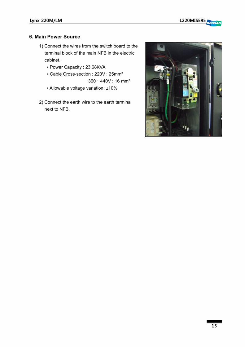
6. Main Power Source
1) Connect the wires from the switch board to the
terminal block of the main NFB in the electric
cabinet.
▪ Power Capacity : 23.68KVA
▪ Cable Cross-section : 220V : 25mm²
360∼440V : 16 mm²
▪ Allowable voltage variation: ±10%
2) Connect the earth wire to the earth terminal
next to NFB.

16
Lynx 220M/LM L220MISE95
7. Power On
7.1 Power On
1) Check if the main power supply, hydraulic
hoses, wires and connectors are properly
connected before switching on the main NFB.
2) To check the rotating direction, press a contact point of KM31 magnate in the electric
cabinet with a wrench or screwdriver, which will drive the hydraulic pump by force.
In case that the pump is driving in the reverse, flip off the switch connecting from the
electric cabinet to the machine to turn off the power, and then switch the U and W wires
(of the main power supply wires) with each other.
3) Once the rotating direction of the motor is determined, press "NC Power On"è and
"Machine Ready" in sequence.
When the hydraulic motor starts running, check if there is a problem in the overall
operation (specifically in the hydraulic hoses) or if there occurs any leak from the
hydraulic hoses or air service unit. In "Machine Ready" mode, the machine diagnoses
the current operation status and displays an alarm if there is a problem to solve.
7.2 Checking the pressure on each unit
1) Hyd. Power Unit : 40.7Kg/cm²

17
Lynx 220M/LM L220MISE95
2) Pressure of the lubrication pump: 15Kg/cm²
▪ If the pressure is below the specified level, it
indicates that there is an oil leak in the
lubrication line. Check the line and take an
appropriate action if necessary.
▪ Oil Specifications
Manufacturer
Lubrication Type MOBIL TOTAL CALTEX Shell Product Oiling points
ISO VG10 VELOCITE
No.6 AZZOLA 10
TELLUS
C10
ISO VG32 DTE 24
(NUTOH-32)
DROSERA
ZS32
RANDO HD-
32
Shell Tellus
32
Hyd. Power
unit
ISO VG68 Vactra #2 DROSERA
MS68
Way
lubricant 68
Shell Tonna
T 68
Guide ways
ball screws
Lithium soap type
Multi-purpose
grease
Mobilux
grease 2
Multifax 2 or
Multifax Ep2
Shell Alvania
EP(LF) 2
Power
chuck jaws
& Turret
Remark 1: We do not recommend you to use anything other than listed above. Since the
lubricant applying to the slideway contains extreme pressure additives, it may
cause unknown issues if responding chemically to other types of oil or coolant.
Remark 2: For fueling points and liters, refer to the user manual of each applicable model.
Remark 3: The lubricant used with coolant or the lubricant used with hydraulic fluid may
cause corrosion in the lubrication unit, resulting in defunctionalized lubrication
and damage to the slideway or the bolts. (IMPORTANT: The company shall not
take responsibility for any error caused by your using disapproved types of oil)
Remark 4: For oils applied to optional devices such as the special chuck or chip conveyor,
refer to the special instructions that ship with the optional device.
Remark 5: If you encounter a problem with the lubricant mixed with the coolant for the
slideway, prepare the oil skimmer before contacting us at our local office.
※ Spindle Lubrication System
By factory default, all spindle bearings are filled with high-quality grease for permanent
lubrication. So you don't need to refill it ever again.
18
Lynx 220M/LM L220MISE95
8. Machine Leveling
1) Machine leveling
The precision on the parallelism for a machine is quite important as it can affect the
processing accuracy and life cycle of the machine significantly. Pay special attention to
the parallelism at the initial installation.
Model Number of bolts for leveling Description
Lynx220/L, Lynx220G, Lynx220LM/M 5EA
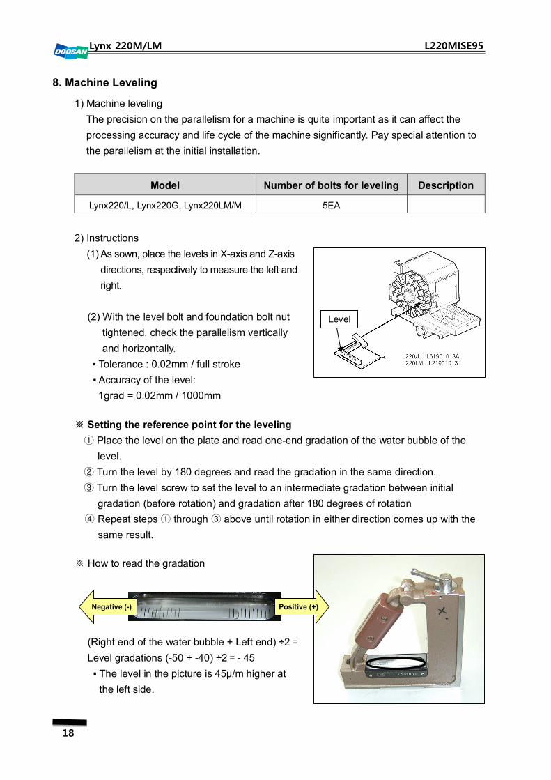
2) Instructions
(1) As sown, place the levels in X-axis and Z-axis
directions, respectively to measure the left and
right.
(2) With the level bolt and foundation bolt nut
tightened, check the parallelism vertically
and horizontally.
▪ Tolerance : 0.02mm / full stroke
▪ Accuracy of the level:
1grad = 0.02mm / 1000mm
※ Setting the reference point for the leveling
① Place the level on the plate and read one-end gradation of the water bubble of the
level.
② Turn the level by 180 degrees and read the gradation in the same direction.
③ Turn the level screw to set the level to an intermediate gradation between initial
gradation (before rotation) and gradation after 180 degrees of rotation
④ Repeat steps ① through ③ above until rotation in either direction comes up with the
same result.
※ How to read the gradation
(Right end of the water bubble + Left end) ÷2=
Level gradations (-50 + -40) ÷2=- 45
▪ The level in the picture is 45μ/m higher at
the left side.
Level
Negative (-) Positive (+)

19
Lynx 220M/LM L220MISE95
① In the meantime, feed the Z axis of Lynx220M in three divided strokes (110mm ≒
330mm ÷ 3) and read the level in each stroke.
② The measurement may vary depending on your view position due to the distance
between gradation of the level and water bubble tube. So you must read the
gradation vertically at 90 degrees against the level.
※ Precautions for the leveling work
① Apply force as evenly as possible to each level bolt.
▪ If any one of the level blocks contacts on the bed unevenly, it may cause an
incorrect leveling in the end.
② The last step of the leveling should be ended in the direction that the level bolt is
tightened.
X axis
Z axis 15
10 20
25 30
30 X axis: 20
Z axis: 15

20
Lynx 220M/LM L220MISE95
9. Machine Precision
9.1 Parallelism between center line of spindle and Z-axis movement
※ In general, the parallelism should be measured using the test bar but it is rarely
available on site. Use an on-site workpiece as an alternative to the test bar.
▪ If the test bar is not available on site and making a workpiece does not work out either,
use the outer-diameter side of the chuck as an alternative.
① Install the indicator on the tool holder of the turret, and present the gauge to the
highest point of the chuck in the X-axis movement (the gauge passes through the
center line of the chuck while lowering the X axis).
② While rotating the chuck manually, check the runout changes of the gauge and stop
rotating the chuck at the middle point of the changes.
③ Move the Z axis by about 100mm and measure the parallelism between center line of
the spindle and Z-axis movement.
▪ Target: below 0.005 mm/100 mm
1) Insert a workpiece (made of soft metal such as
aluminum in Φ50×L150) into the chuck and
perform the rough cut then finishing cut.
2) Use the micrometer to measure the overall
length between two points (“A”, “B”).
▪ If the difference between A and B is more
than 0.01mm/100mm, you must adjust the
head stock position.
3) Adjusting the head stock
① Install the indicator on the tool holder of the
turret. While moving the Z axis, check the X-
axis deviations (normally, no deviation is
allowed) and set the end of the workpiece to
0.
② Use the 17mm L-wrench to loosen the bolts (5-BB 20×80) on the head stock slightly.
③ If B is greater than A in step ② above, tighten C; if not, tighten D approximately 2.5
times of the error while reading the indicator.
공작물 (Φ50×L150)
Chuck
Workpiece(Φ50×L150)
Chuck
공작물 (Φ50×L150)Workpiece(Φ50×L150)
공작물 (Φ50×L150)
Chuck
“A” “B”
Workpiece(Φ50×L150)
21
Lynx 220M/LM L220MISE95
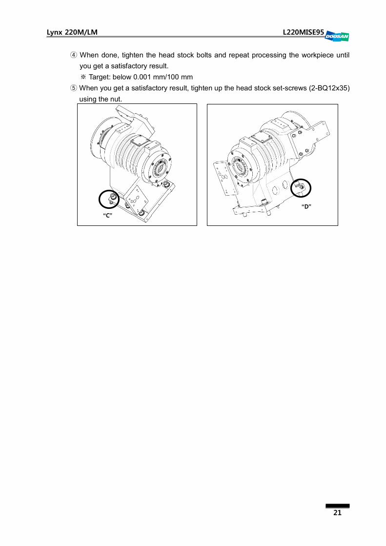
④ When done, tighten the head stock bolts and repeat processing the workpiece until
you get a satisfactory result.
※ Target: below 0.001 mm/100 mm
⑤ When you get a satisfactory result, tighten up the head stock set-screws (2-BQ12x35)
using the nut.
“C”
“D”
22
Lynx 220M/LM L220MISE95
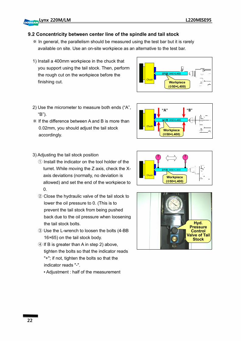
9.2 Concentricity between center line of the spindle and tail stock
※ In general, the parallelism should be measured using the test bar but it is rarely
available on site. Use an on-site workpiece as an alternative to the test bar.
1) Install a 400mm workpiece in the chuck that
you support using the tail stock. Then, perform
the rough cut on the workpiece before the
finishing cut.
2) Use the micrometer to measure both ends (“A”,
“B”).
※ If the difference between A and B is more than
0.02mm, you should adjust the tail stock
accordingly.
3) Adjusting the tail stock position
① Install the indicator on the tool holder of the
turret. While moving the Z axis, check the X-
axis deviations (normally, no deviation is
allowed) and set the end of the workpiece to
0.
② Close the hydraulic valve of the tail stock to
lower the oil pressure to 0. (This is to
prevent the tail stock from being pushed
back due to the oil pressure when loosening
the tail stock bolts.
③ Use the L-wrench to loosen the bolts (4-BB
16×65) on the tail stock body.
④ If B is greater than A in step 2) above,
tighten the bolts so that the indicator reads
"+"; if not, tighten the bolts so that the
indicator reads "-".
▪ Adjustment : half of the measurement
Chuck
공작물 (Φ50×L400)
Chuck
공작물 (Φ50×L400)
Hyd. Pressure Control
Valve of Tail Stock
Chuck
공작물 (Φ50×L400)
“A” “B”
Workpiece
(Φ50×L400)
Workpiece
(Φ50×L400)
Workpiece
(Φ50×L400)
23
Lynx 220M/LM L220MISE95
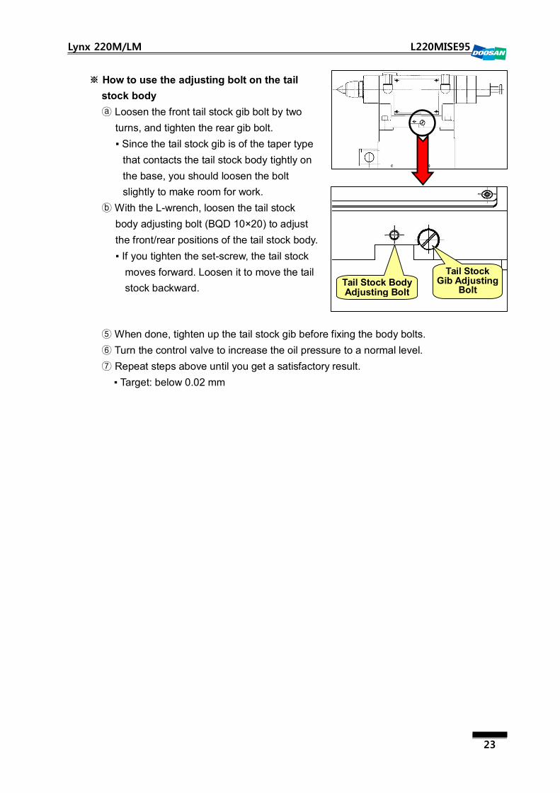
※ How to use the adjusting bolt on the tail
stock body
ⓐ Loosen the front tail stock gib bolt by two
turns, and tighten the rear gib bolt.
▪ Since the tail stock gib is of the taper type
that contacts the tail stock body tightly on
the base, you should loosen the bolt
slightly to make room for work.
ⓑ With the L-wrench, loosen the tail stock
body adjusting bolt (BQD 10×20) to adjust
the front/rear positions of the tail stock body.
▪ If you tighten the set-screw, the tail stock
moves forward. Loosen it to move the tail
stock backward.
⑤ When done, tighten up the tail stock gib before fixing the body bolts.
⑥ Turn the control valve to increase the oil pressure to a normal level.
⑦ Repeat steps above until you get a satisfactory result.
▪ Target: below 0.02 mm
Tail Stock Gib Adjusting
Bolt Tail Stock Body Adjusting Bolt
24
Lynx 220M/LM L220MISE95
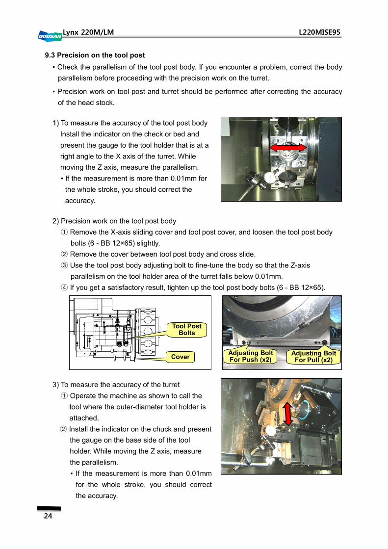
9.3 Precision on the tool post
▪ Check the parallelism of the tool post body. If you encounter a problem, correct the body
parallelism before proceeding with the precision work on the turret.
▪ Precision work on tool post and turret should be performed after correcting the accuracy
of the head stock.
1) To measure the accuracy of the tool post body
Install the indicator on the check or bed and
present the gauge to the tool holder that is at a
right angle to the X axis of the turret. While
moving the Z axis, measure the parallelism.
▪ If the measurement is more than 0.01mm for
the whole stroke, you should correct the
accuracy.
2) Precision work on the tool post body
Remove the X① -axis sliding cover and tool post cover, and loosen the tool post body
bolts (6 - BB 12×65) slightly.
Remove the cover ② between tool post body and cross slide.
Use the tool post body adjusting bolt to fine③ -tune the body so that the Z-axis
parallelism on the tool holder area of the turret falls below 0.01mm.
If you get a satisfactory result, tighten up the tool post body④ bolts (6 - BB 12×65).
3) To measure the accuracy of the turret
Operate the machine as shown to call the ①
tool where the outer-diameter tool holder is
attached.
Install the indicator on the chuck and present ②
the gauge on the base side of the tool
holder. While moving the Z axis, measure
the parallelism.
▪ If the measurement is more than 0.01mm
for the whole stroke, you should correct
the accuracy.
Cover
Tool Post Bolts
Adjusting Bolt For Push (x2)
Adjusting Bolt For Pull (x2)

25
Lynx 220M/LM L220MISE95
4) Correct
Remove the tool and tool holder from the ①
turret. (Take a note of the numbers if
necessary)
Move the Z2 axis to facilitate the work.②
(proper position for the measuring)
Remove L73563042A location disk.③
Use the pin ④ puller to remove the positioning
pins from the turret.
▪ P57208050 TAPER PIN TPB8X50
▪ L32563174A FIXTURE
Loosen the curvic coupling bolts slightly from ⑤
the turret.
▪ BB10 X 80 = 8EA
With a plastic hammer or wood support, ⑥
impact on the turret head to make
adjustment within the tolerance.
When done, tighten up the bolts and perform ⑦
the reaming of the pin hole again using M7
taper reamer before inserting the taper pin.
(Do the same on the hole for each of two
spare taper pins.)
Install the location disk according to the ⑧
number.
Taper Pin FIXTURE
26
Lynx 220M/LM L220MISE95
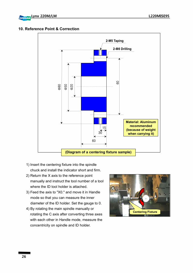
10. Reference Point & Correction
1) Insert the centering fixture into the spindle
chuck and install the indicator short and firm.
2) Return the X axis to the reference point
manually and instruct the tool number of a tool
where the ID tool holder is attached.
3) Feed the axis to "X0." and move it in Handle
mode so that you can measure the inner
diameter of the ID holder. Set the gauge to 0.
4) By rotating the main spindle manually or
rotating the C axis after converting three axes
with each other in Handle mode, measure the
concentricity on spindle and ID holder.
Centering Fixture
2-M5 Taping
2-Φ8 Drilling
15
30
60
Φ20 60
Φ50
Φ80
Material: Aluminum recommended
(because of weight when carrying it)
(Diagram of a centering fixture sample)
27
Lynx 220M/LM L220MISE95
5) Move the X axis in Handle mode to set the indicator to 0 and check the error against the
Y axis.
Since the error is the height error of the turret, make correction of the adjusting plate ※
according to the error.
6) Return to the reference point and enter half of the error (step 5 above) in "Parameter
No.1850 Grid Shift". Check if the X value of "Parameter No.1815#4(APZ)" is changed to
0.
7) When the alarm message of "P/S Alarm 000 Please Turn Off Power” is displayed, turn
off the machine and turn it back on in a moment.
8) Return the X axis to the reference point manually.
The X and Y values of ※ "Parameter No.1815 #4(APZ)" will be changed from 0 back to
1.
9) Repeat steps 2) through 5) above until you get a satisfactory result.

28
Lynx 220M/LM L220MISE95
11. Q-Setter Operation
1) Q-Setter related Keep Relay settings and M codes
Keep Relay M Code Description
K7.5 Enable Q-setter (→1), disabled (→0)
M80 Q- Setter Swing Arm Down
M81 Q- Setter Swing Arm Up
2) Check the Q-Setter operations of Swing Arm Up/Down
① Ensure that the chuck is inserted in the workpiece and that no collision occurs within
the Q-Setter operation range.
② Use the Q-Setter control buttons or M codes to check the operation of Swing
Up/Down.
③ Check if no coolant inflows during the operation of Q-Setter ARM Up
3) Q-setter position (outer diameter)
Prepare a workpiece that you can ①
measure the outer diameter of.
Insert the finishing tool into the turret and ②
process the whole outer-diameter side of
the workpiece evenly.
▪ When completed, the X axis should not
move at all.
③ With the micrometer, measure the diameter of the completed workpiece.
Compare the measurement (outer diameter) with the X-axis coordinates and
calculate the error.
▪ Enter the error in the applicable parameter number or change the machine position
itself accordingly.
Follow the same steps above for measuring ※
the inner diameter.
Axial Direction X-axis
+ direction X-axis
- direction Z-axis
+ direction Z-axis
- direction
Parameter No. 5015 5016 5017 5018
X – Direction
Z – Direction Z +
Direction
X + Direction
Tool Setting Direction
29
Lynx 220M/LM L220MISE95
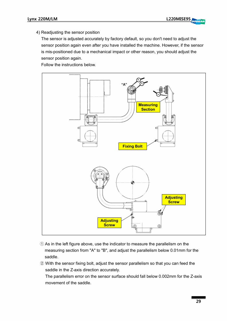
4) Readjusting the sensor position
The sensor is adjusted accurately by factory default, so you don't need to adjust the
sensor position again even after you have installed the machine. However, if the sensor
is mis-positioned due to a mechanical impact or other reason, you should adjust the
sensor position again.
Follow the instructions below.
As in the left figure above, use the indicator to measure the parallelism on the ①
measuring section from "A" to "B", and adjust the parallelism below 0.01mm for the
saddle.
With the sensor fixing bolt, adjust the sensor parallelism so that you can feed the ②
saddle in the Z-axis direction accurately.
The parallelism error on the sensor surface should fall below 0.002mm for the Z-axis
movement of the saddle.
“A”
“B”
Measuring Section
Fixing Bolt
Adjusting Screw
Adjusting Screw
30
Lynx 220M/LM L220MISE95
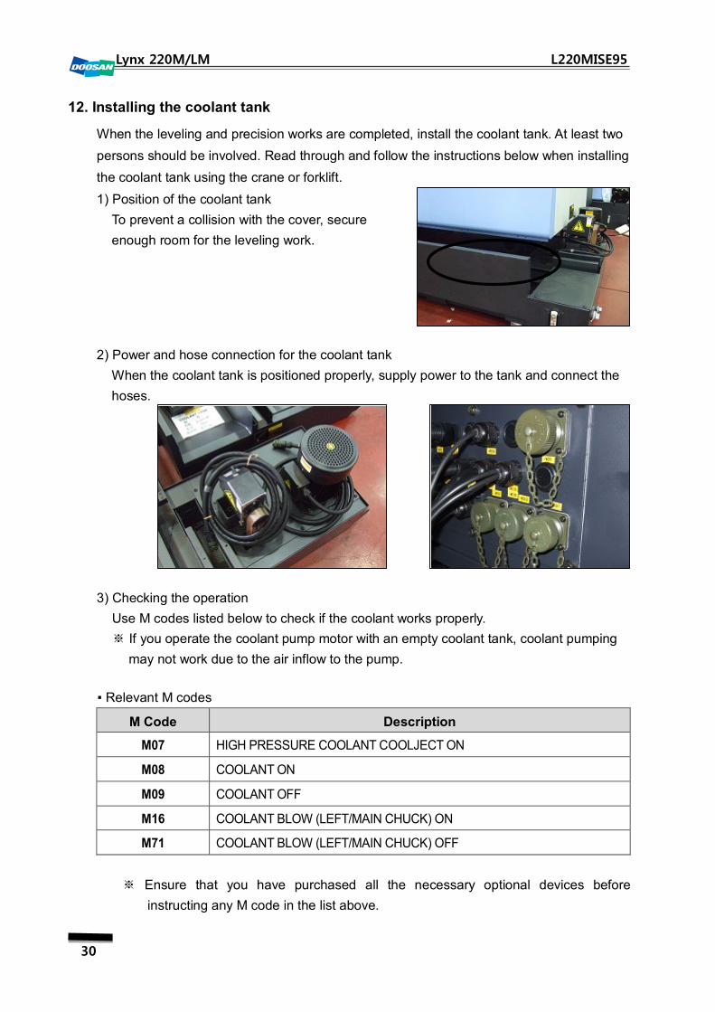
12. Installing the coolant tank
When the leveling and precision works are completed, install the coolant tank. At least two
persons should be involved. Read through and follow the instructions below when installing
the coolant tank using the crane or forklift.
1) Position of the coolant tank
To prevent a collision with the cover, secure
enough room for the leveling work.
2) Power and hose connection for the coolant tank
When the coolant tank is positioned properly, supply power to the tank and connect the
hoses.
3) Checking the operation
Use M codes listed below to check if the coolant works properly.
If you operate the coolant pump motor with an empty ※ coolant tank, coolant pumping
may not work due to the air inflow to the pump.
▪ Relevant M codes
M Code Description
M07 HIGH PRESSURE COOLANT COOLJECT ON
M08 COOLANT ON
M09 COOLANT OFF
M16 COOLANT BLOW (LEFT/MAIN CHUCK) ON
M71 COOLANT BLOW (LEFT/MAIN CHUCK) OFF
Ensure that you have purchased all the necessary optional devices before ※
instructing any M code in the list above.

31
Lynx 220M/LM L220MISE95
Revision History Installation Manual Lynx 220M/LM
Version Year/Month Revision history Created by
01 2009. 05 Official draft (L220MISE95) Jeong, Sam Young
02
03
04
05
06
07
08
09
10