Embed Size (px)
Citation preview

MCG Inc. BMC 12H Hardware Installation Manual ZN2UD12H99-5
BMC 12H
HARDWARE INSTALLATION MANUAL


_______________________________________________________________________________________________ Page - 1 -
MCG Inc. BMC 12H – Hardware Installation
1.0 Overview of BMC 12H
1.1 BMC 12H Definition
MCG BMC 12H is a PWM brushless servo drive designed to drive brushless type DCservo motors at a high switching frequency. Operating efficiencies approach 99 %.
1.2 Functional Block Diagram
Figure (1) Functional Block Diagram
1.3 Drive Features Analog interface, !10 volts analog interface. Single red/green LED indicates operating status. Over voltage protection. Over current protection. Over temperature protection. Short circuit protection across motor, ground and power leads. Designed to interface with digital controllers or could be used as a stand-alone drive. Requires a single (1 φφ) phase or three (3 φφ) phase AC power source (70 - 270 Vac). Loop Gain, Current Limit, Command Gain and Offset can be adjusted using 15 turn
potentiometers. The Offset adjusting potentiometer can also be used as an onboard input signal for testing
purposes when SW-1 is ON (position 1 of the DIP switch is ON). Agency approvals, UL recognized.

_______________________________________________________________________________________________ Page - 2 -
MCG Inc. BMC 12H – Hardware Installation
1.4 General SpecificationsBMC 12H
Supply Voltage (1) 70 - 270 Vac Peak Output Current (2 sec) ±25 Amp Maximum Continuous Current ±12.5 Amp Power Dissipation @ Cont. Current 55 Watts Shunt Turn On 390 Volts DC
(1) Single or three phase operation.
Automatic Current Reduction 50 % OR 25 %Switch Selectable Switching Frequency 20 kHz Minimum Load Inductance 660 micro H Input Command Signal Range ± 10 Volts (+-15 Volts DC max.) Input Impedance 50 Kohms Tach Input 60 Kohm, +- 60 Volts Current Monitor Output Amps to Volts Velocity Monitor Output RPM to Volts Operating Temperature 32 - 122 F (0 - 50 C) Storage Temperature -40 - 176 F (-40 - 80 C) Relative Humidity 5% - 95% non-condensing Power Connectors Screw Terminal Signal Connector Molex Connector Size 8.00 X 6.35 X 3.43 Weight 4.8 lb
Specifications Table
1.5 System Connection/Wiring Diagram
The following diagram shows an installation of the BMC 12H in a typical system. Yoursystem may vary from this configuration. Typical components used with the BMC 12Hbrushless servo drive include:
Brushless DC servo motor. External switches. AC power source

_______________________________________________________________________________________________ Page - 3 -
MCG Inc. BMC 12H – Hardware Installation
Figure (2) Wiring and Connections Diagram
1.6 How to Use This Manual
This manual provides and contains information, procedures and instructions on how toinstall, connect, set up and test the BMC 12H brushless servo drive. This manual isorganized into chapters and appendices.
1.7 Warranty
The MCG BMC 12H has a two-year warranty against defects in material and assembly.Products that have been modified by the customer, physically mishandled or otherwiseabused through miswiring, incorrect switch settings and so on, are exempt from thewarranty plan.

_______________________________________________________________________________________________ Page - 4 -
MCG Inc. BMC 12H – Hardware Installation
2.0 Installing the BMC 12H
This chapter explains how to install the BMC 12H brushless servo drive in yourapplication.
2.1 Unpacking the Drive
Remove the drive from the shipping carton and remove all packing materials from thebrushless servo drive. The materials and the carton may be retained for storage orshipment of the drive.
Check all items against the packing list. A label located on the side of the driveidentifies: Model number Serial number Manufacturing date code
2.2 Inspection Procedure
To protect your investment and ensure your rights under warranty, MCG recommends thatthe following steps be performed upon receipt of the drive: Inspect the drive for any physical damage that may have been sustained during
shipment. Perform procedures described in section 2.2.1 before storing or installing the servo
drive If you find damage, either concealed or obvious, contact your buyer to make claim with
the shipper. Contact your distributor to obtain a Return Material Authorization (RMA)number. Do this as soon as possible after you receive the BMC 12H drive.
2.2.1 Testing the BMC 12H Brushless Servo Drive
The BMC 12H is designed to operate in a self-test mode using POT 4, the Offset / Testpotentiometer, to control an onboard signal source. This test can be used to confirm thatthe servo drive is functional and operational. The test requires an AC power source (70 -270 Vac, single or three phase), a multimeter, and a DC brushless servo motor.
1. Take note of the DIP switch settings before starting the test.2. Always be prepared to turn the main power OFF.3. Refer to figure (2) “Wiring and Connection Diagram.”4. Set the DIP switch on the servo drive to the following settings, “positions”:
SW1 SW2 SW3 SW4 SW5 SW6 SW7 SW8 SW9 SW10 ENC TACHON OFF OFF OFF ON OFF ON OFF OFF ON NC NC
5. Set the “CURRENT LIMIT” POT 2 to the motor specifications, use the following tablefor the approximated current settings:

_______________________________________________________________________________________________ Page - 5 -
MCG Inc. BMC 12H – Hardware Installation
SW3 OFFSW8 OFF
SW3 OFFSW8 ON
SW3 ONSW8 ON
SW3 ONSW8 OFF
Number ofturns fromFully CCW ICont IPeak ICont IPeak ICont IPeak ICont IPeak
5 !1.0 !4.17 !2.1 !4.2 !4.2 !8.4 !2.1 !8.410 !2.1 !8.4 !4.2 !8.4 !8.3 !16.7 !4.2 !16.815 !3.125 !12.5 !6.25 !12.5 !12.5 !25 !6.25 !25
6. Connect COMM A, B and C (hall) sensors to P1 pins 12, 13 and 14 3 respectively.7. Connect the COMM (hall) power leads to P1-10, and COMM GND to P1-11.8. DO NOT CONNECT THE MOTOR LEADS (PHASES R, S AND T) YET.9. Connect your AC power, then apply power by turning the AC power source ON.10. Check that the LED is GREEN (normal operation).11. Turn the motor shaft manually one revolution; the LED should remain GREEN. If the
LED is RED or changes color: Check 60/120 degree phase switch setting (SW10, MCG setting is ON). Check power to COMM (hall) sensors. Check voltage levels for the COMM (hall) input.
12. Turn the AC power source OFF and wait for about 10 seconds (or till the LED is OFF).13. Connect the motor leads, phases R, S and T to P2 pins 1, 2 and 3 respectively.14 Turn the AC power source ON (LED should be GREEN for normal operation).15. Verify smooth operation by turning the “TEST/OFFSET” potentiometer, POT 4, fully CW then fully CCW; motor should run smooth and reverse in both directions.16. Turn the “TEST/OFFSET” potentiometer, POT 4, till the motor stops rotating.17. Turn the AC power source OFF.18. Set the DIP switch settings to the original factory settings or to your suitable mode.
If the drive passed the above test, proceed to the next section and if not refer to section 4.0“Maintenance / Troubleshooting.”
2.3 Storing the Drive
Return the drive to its shipping carton using the original packing materials. Store the drivein a clean, dry place that will not exceed the following conditions: Humidity: 5% to 95%, non-condensing. Storage temperature: -40 - 176 F (-40 to 80 degrees C).
2.4 Selecting a Motor
The BMC 12H brushless servo drive is compatible with many brushless DC servo motors,both MCG brushless DC servo motors and motors from other manufacturers. The motorwinding current rating must be equal or less to the output current setting of the drive.
Refer to the torque speed curve in the CfD “Brushless Servo Components” catalog orcontact your local MCG distributor for motor sizing and compatibility assistance.

_______________________________________________________________________________________________ Page - 6 -
MCG Inc. BMC 12H – Hardware Installation
2.5 Safety
Read the complete manual before attempting to install or operate the BMC 12H drive. Byreading the manual you will become familiar with practices and procedures that allow youto operate this drive safely and effectively.
As a user or person installing this drive, you are responsible for determining the suitabilityof this product for the intended application. MCG is neither responsible for nor liable forindirect or consequential damage resulting from the inappropriate use of this product.
2.5.1 Safety Guidelines
Electrical shock and hazards are avoided by using normal installation procedures forelectrical power equipment in an industrial environment. The drive should be installed inan industrial cabinet such that access is restricted to suitable qualified personnel.
Electrical hazards can be avoided by disconnecting the drive from its power source andmeasuring the AC voltage to verify that it is within the safe level (70 - 270 Vac).
Make sure motor case is tied to earth ground. DO NOT power the unit without the cover. DO NOT operate the unit without connecting the motor to the appropriate terminals.
High voltage is present at the motor terminal, even when motor is not connected. Always remove power before making any connection to the drive. Always turn OFF the main power before taking the cover off the drive. DO NOT make any connections to the internal circuitry. Connections on the front
panel are the only points where users should make connections. DO NOT use the ENABLE input as a safety shutdown. Always remove power to the
drive for safety shutdown. Make sure the minimum inductance requirement is met. DO NOT spin the motor without power. The motor acts like a generator and will
charge up the power capacitor through the drive. Excessive speed may cause overvoltage breakdown in the power MOSFETs. Note that the drive, having an internalpower converter, which operates from the high voltage, will become operative.
DO NOT short the motor at high speed. When the motor is shorted, its own generatedvoltage may produce a current flow as high as 10 times the drive peak current. Theshort itself should not damage the drive but may damage the motor. If the motor isspinning rapidly and the motor connections arc or open, a high voltage pulse flowsback into the drive (due to stored energy in the motor inductance) and may damage thedrive.
WARNING
Voltage potential inside the drive varies from 380 Volts above to 380 Volts below earthground. All internal circuitry should be considered “hot” when power is present.

_______________________________________________________________________________________________ Page - 7 -
MCG Inc. BMC 12H – Hardware Installation
2.6 Mechanical Installation
Mount the drive in an enclosure providing protection to IP54, protected against dust andsplashing water, or IP65, protected against water jets and dust free air. Many NEMA type4 cabinets provide this level of protection. Minimum cabinet requirements are: Depth 7 inches. Ventilation to dissipate 55 watts. The air should also be free of corrosive or electrically conductive contaminants. Internal cabinet temperature should not exceed 122 F (50 degrees C). Operating
temperature range is 32 - 122 F (0 - 50 degrees C). 2.6.1 Mounting Dimensions
Figure (3) Mechanical Dimensions
Position the drive in vertical position on a flat, solid surface. This surface should be ableto support 4.8 lb (2.2 Kg), the approximate weight of the drive. Bolt the drive in the cabinet using the two mounting slots in the rear side, or the four
mounting slots in the side of the drive (cold plate mounting), using M4 or size 6-32screws.
Maintain a minimum unobstructed distance of 4 inches (100 mm) at the top and bottomof the drive.
Maintain a minimum distance of one inch on each side of the drive. The surface should be free of excessive vibration or shock.

_______________________________________________________________________________________________ Page - 8 -
MCG Inc. BMC 12H – Hardware Installation
2.7 Electrical Interfacing and Connections
The servo drive has three I/O (input/output) connectors. P1 - Signal connector, Molex type, 16-pin connector. P2 - Motor connector, screw terminal, 3-pin connector. P3 - Encoder connector, Molex type, 5-pin connector.
2.7.1 Interface Connection Diagram
Figure (4) Wiring and Connections Diagram
2.7.2 Wiring
Wiring sizes and practices as well as grounding and shielding techniques described in thissection represent common wiring practices and should prove satisfactory in the majority ofapplications.

_______________________________________________________________________________________________ Page - 9 -
MCG Inc. BMC 12H – Hardware Installation
Due to the switching nature of this PWM drive, care should be exercised in routing powerand signal wiring in the system. Noise radiated from nearby electrical or electronicequipment may cause undesired servo motor movement due to pickup by the drive’s signalinputs. Likewise, the drive power outputs can generate noise which could be picked up bythe drive’s signal inputs or by other electronic equipment located near the controller’soutput wiring.
To reduce the possibility of noise pickup, power and signal lines should be twisted,shielded and routed separately. Ideally the power signal lines should run in separateconduits or be paced at least 12” apart.
WarningThe user is responsible for conforming to all applicable local, national and international
codes. Wiring practices, grounding disconnects and over current protection are ofparticular importance. Nonstandard applications, special operating conditions, and
system configurations may differ from what's described in this section.
NoteThe grounding connections for the AC power, chassis, and motor must be connected as
shown in the interface connection diagram.
Refer to Appendix B for more information
2.7.3 P2 - Motor Wiring
Twisted, shielded pair wiring for motor cabling is recommended. Ground the shield endonly at the drive end as shown in figure (4). The motor power inputs are connected to thedrive output.
Cable requirements: Use #14 to #16 AWG for cabling. Obtain twisted wire cable. If thecable used is shielded, connect the shield to the drive end only; refer to figure (4) “Wiringand Connections Diagram.”
NOTES
1. DO NOT use wire shield to carry motor current.2. DO NOT solder or pre-tin the tips of the cable going into the screw terminal
connector, solder will contract and will result in loose connections over time.
MCG offers pre-made cables for easier connectivity with it Automation Line Duty (ABseries) brushless line servomotors.
Refer to Appendix A, B and C for more information

_______________________________________________________________________________________________ Page - 10 -
MCG Inc. BMC 12H – Hardware Installation
2.7.4 P1 - Signal Connector
This is a 16 pin Molex type I/O (input and output) connector. The Molex matingconnector part numbers are:
Molex Plastic Body 22-01-3167Insert Terminals 08-50-0114
The standard crimping hand tool is:Molex part number 11-01-0185
The following table shows the pin assignment and the functionality along with a briefdescription of each pin.
P1 pin NO. Function Function / Description1 +10 Vdc @ 5
mAmp2 Signal GND3 -10 Vdc @ 5
mAmp
For customer use. Internal AC-DC converter which generates the internal +/-
12 Vdc from the high DC power supply input, and alsooutputs regulated voltages of +/- 10 Vdc @ 5 mΑ.
These are short circuit protected.4 COMMAND -5 COMMAND +
Analog command signal, a differential type signal to drivethe servo drive.
In velocity mode, the differential COMMAND signal is thevelocity command.
In torque (current) mode, the differential COMMANDsignal is the torque or current command.
Separate scale and offset adjustments are used inconjunction with this input.
Input impedance of 50 kW. Maximum input voltage +/- 15 Volts.
6 - TACH IN The negative tachometer input. Maximum input impedance 60 kW. Maximum input voltage +/- 60 Volts.
7 VELMONITOR
OUT
Velocity monitor output. 1 V = 25 kHz encoder pulse frequency. 1 V = 100 Hz hall velocity mode.
8 CURRENTMONITOR
This output signal is proportional to the actual current in themotor leads.
Scaling is 2 Amps / 1 Volt when SW3 is OFF. Scaling is 4 Amps / 1 Volt when SW3 is ON.
9 ENABLE The servo drive will be disabled if this pin is pulled to
ground (pin 2 SIGNAL GND). To reverse this functionality (pulling this pin to ground, pin
2 SIGNAL GND will enable the drive), simply remove J1 (ablack color surface mount component with three zeroswritten on it and surrounded by a white box) form the insidethe unit.

_______________________________________________________________________________________________ Page - 11 -
MCG Inc. BMC 12H – Hardware Installation
10 +V Hall11 GND
+5V output @ 30 mΑ, short circuit protected. Power for theHall sensors.
12 COMM A13 COMM B14 COMM C
The commutator channel inputs (Halls). Logic levels, internal 2 kW pull-ups. Maximum low-level input is 1.5 V. Minimum high level input is 3.5 V.
15 CURRENTREF OUT
Monitors the input signal connected directly to the internalcurrent amplifier.
Scaled to 7.5 Vdc = 25 Amps.16 FAULT
OUTPUT Under no fault condition this output is low. Under a fault condition this output is high. Faults are output short circuit, over voltage, over
temperature, disable and during power on reset. Fault condition indicated by red LED.
Note
Fault conditions are NOT LATCHED. When a faultcondition is removed, the drive will be enabled and canresume motion if commanded.
P1 Signal Interface Connector
For the internal circuit representations of the above connection points, refer to figure(1) “Functional Block Diagram.”
2.7.5 COMM (hall sensors) Wiring
Twisted 22 AWG shielded cable is the minimum requirement for COMM (hall sensor)cabling. Ground the shield at the drive end only; refer to figure (4), “Wiring andConnections Diagram.”
Refer to Appendix B for more information.
2.7.6 COMMAND Signal Wiring
Twisted, shielded pair wire for the COMMAND input signal is recommended.Connect the shield to the command signal source and not to the drive.
If the command signal source is ungrounded, connect the shield to both the source andthe drive ground.
It is recommended that the input be connected directly to the drive differential input. If the signal command source and the drive are grounded to the master chassis ground,
leave the source end of the shield unconnected. The drive-input circuit will attenuatethe common mode voltage between the signal command source and the drive powergrounds.
If the direction of motor rotation is not the desired one, reverse the polarity on theCOMMAND input or interchange COMM A & COMM C; then motor leads R & S.
Refer to figure (4), and appendix B for more information.

_______________________________________________________________________________________________ Page - 12 -
MCG Inc. BMC 12H – Hardware Installation
2.7.7 P2 - Motor Connections
P2 is a 3-pin screw terminal connector, which connects the drive to the motor phases.
P2 Pin NO Signal Description1 MOTOR PHASE R R phase power to motor.2 MOTOR PHASE S S phase power to motor.3 MOTOR PHASE T T phase power to motor.
P2 Motor Interface Connection
Cable requirements: Use #14 to #16 AWG for cabling, twisted.
MCG supplies pre-made cables for the Automation Duty Brushless Line servomotors.
NOTES1. DO NOT solder or pre-tin the tips of the cable going into the screw terminal
connector, solder will contract and will result in loose connections over time.2. DO NOT use wire shield to carry power current and voltage.
Refer to Appendix A, B and C for more information
2.7.8 P3 - Encoder Connector
This is a 5 pin Molex type I/O (input and output) connector. The Molex mating connectorpart numbers are:
Molex Plastic Body 22-01-3057Insert Terminals 08-50-0114
The standard crimping hand tool is:Molex part number 11-01-0185
The following table shows the pin assignment and the functionality along with a briefdescription of each pin.
P3 pin NO. Function Function / Description
1 +5 Vdc Encoder power (output). Rated current 500 mΑ.
2CHANNEL
A The Encoder input (quadrature). Maximum input voltage 5 Volts (CMOS).
3 NC Not Connected There should be no connections made to this pin.
4CHANNEL
B The Encoder input (quadrature). Maximum input voltage 5 Volts (CMOS).
5 GND Reference ground for the encoder signals. Connect the +5 Vdc return (common of the power supply) to this point.
P3 Encoder Signals Interface Connector

_______________________________________________________________________________________________ Page - 13 -
MCG Inc. BMC 12H – Hardware Installation
2.7.8.1 Encoder Wiring
Twisted 22 AWG shielded pair cable is the minimum requirement for encoder cabling.Ground the shield at the drive end only; refer to figure (4) “Wiring and ConnectionsDiagram.”
There are two ways for proper electrical connection:
If the +5 Vdc is available from the customer controller1. Connect all encoder signals from the motor to the controller2. Connect encoder power to the controller3. Connect the GND from the controller to the GND pin on the BMC12H (P3-5)4. Refer to the connection diagram on page 8, figure 4 (use the doted connections)5. Refer to section 3 for the proper mode selections and connections
If the +5 Vdc is NOT available from the customer controller1. Connect all encoder signals from the motor to the controller2. Connect encoder power to the BMC12H (P3-1 & P3-5)3. Connect the GND from the controller to the GND pin on the BMC12H (P3-5)4. Refer to the connection diagram on page 8, figure 4 (use the solid connections)5. Refer to section 3 for the proper mode selections and connections
The MCG encoders require 5 Vdc @ 150 mA).It is very important to tie the common of the power supply to P3-5.
Refer figure 4 and to Appendix B for more information
_______________________________________________________________________________________________ Page - 14 -
MCG Inc. BMC 12H – Hardware Installation
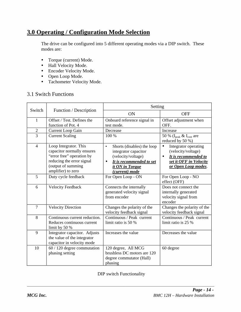
3.0 Operating / Configuration Mode Selection
The drive can be configured into 5 different operating modes via a DIP switch. Thesemodes are:
Torque (current) Mode. Hall Velocity Mode. Encoder Velocity Mode. Open Loop Mode. Tachometer Velocity Mode.
3.1 Switch Functions
SettingSwitch Function / Description
ON OFF1 Offset / Test. Defines the
function of Pot. 4Onboard reference signal intest mode.
Offset adjustment whenOFF.
2 Current Loop Gain Decrease Increase3 Current Scaling 100 % 50 % (Ipeak & Icont are
reduced by 50 %)4 Loop Integrator. This
capacitor normally ensures“error free” operation byreducing the error signal(output of summingamplifier) to zero
• Shorts (disables) the loopintegrator capacitor(velocity/voltage)
It is recommended to setit ON in Torque(current) mode
Integrator operating(velocity/voltage)
It is recommended toset it OFF in Velocityor Open Loop modes.
5 Duty cycle feedback For Open Loop - ON For Open Loop - NOeffect (OFF)
6 Velocity Feedback Connects the internallygenerated velocity signalfrom encoder
Does not connect theinternally generatedvelocity signal fromencoder
7 Velocity Direction Changes the polarity of thevelocity feedback signal
Changes the polarity of thevelocity feedback signal
8 Continuous current reduction.Reduces continuous currentlimit by 50 %
Continuous / Peak currentlimit ratio is 50 %
Continuous / Peak currentlimit ratio is 25 %
9 Integrator capacitor. Adjuststhe value of the integratorcapacitor in velocity mode
Increases the value Decreases the value
10 60 / 120 degree commutationphasing setting
120 degree, All MCGbrushless DC motors are 120degree commutator (Hall)phasing
60 degree
DIP switch Functionality

_______________________________________________________________________________________________ Page - 15 -
MCG Inc. BMC 12H – Hardware Installation
3.1.1 Current Loop Integrator, SW2, R26 and C69
The current loop response (bandwidth) is determined by the current loop gain resistor, referto figure (1) “Functional Block Diagram.” SW2, R26 and C69 control the PI (proportionaland integral) gains of the current loop.
Current loop response is inversely proportional to motor inductance. Higher inductancemotors require higher proportional gain to obtain the same response as lower inductancemotors.
The greater the resistor value the faster the response. If the resistor value is too high forthe inductance, overshoot or oscillation occurs in the current loop.
Typically the standard drive settings: 10 kΩ is recommended for load inductor less than 2 mΗ. 100 kW setting is recommended for more than 2 mΗ.
This may be accomplished by switching on the extra capacitor with the DIP switch SW2 orby installing a through-hole resistor in R26. For load inductors higher than 5 mΗ, a 200mW or higher resistance can be placed in R26 for faster response. If the resistor value istoo high for the inductance, overshoot or isolation occurs in the current loop.
In most applications, leaving SW2 in the OFF position is recommended. By doing sothe signal is being integrated and the error signal is being reduced as well as the amount ofsignal overshoot. If the gain resistor value has been changed, C69 has to change.
Since adjustments of these components can cause possible damage to the drive’s powersection, extreme care should be exercised if changing these components. Consult yourlocal MCG distributor before attempting to change or add components.
3.1.2 Velocity Loop Integrator, SW4, SW9, C67
The velocity loop integrator capacitor can be used to compensate for large load inertia.The greater the load inertia the greater the capacitor value is required. This can be done byswitching SW4 OFF and switching SW9 ON at the same time or by installing a largerthrough hole capacitor (C67), and leaving SW4 and SW9 OFF; refer to figure (1)“Functional Block Diagram.”
Shorting out the velocity integrator capacitor by turning SW4 ON and SW9 OFF canverify the need for a larger capacitor. If the velocity loop is stable with the capacitorshorted out and unstable with the capacitor in the circuit, then a greater capacitor value isneeded.
If the capacitor is included in the circuit (SW4 OFF), it will force the motor velocity toprecisely follow the commanded velocity (reducing the velocity error), this assumingsteady state operation where the velocity command or the load DOES NOT change.

_______________________________________________________________________________________________ Page - 16 -
MCG Inc. BMC 12H – Hardware Installation
The velocity loop integrator along with POT1 “LOOP GAIN” controls the stiffness and theability to reject load torque disturbance. Too high of a capacitor value could cause anovershoot in the velocity loop and may cause the system to become unstable or break intooscillations.
The velocity loop response (bandwidth) is determined by POT 1 (LOOP GAIN). Thegreater the POT value (the more turns from CCW), the faster the response.
3.2 Potentiometer Functions
Potentiometer Function Description Turning CWPot 1 Loop Gain Loop gain adjustments in voltage and velocity modes.
Voltage to current scaling factor adjustment in currentmode.
It is also a function of SW4, SW9 & C67. If in TORQUE (CURRENT) MODE setting, this
potentiometer should be set FULLY CCW, otherwisea runaway condition may occur.
Increasesloop gain
Pot 2 CurrentLimit
Adjusts both continuous and peak current limit bymaintaining a ratio of 2:1 (peak: continuous).
It is also a function of SW3 & SW8.
Increasescurrent limit
Pot 3 CommandGain
Adjusts the ratio between the input COMMANDsignal and the output variables (voltage, current, andvelocity).
Turn this POT CW until the required output isobtained for a given input COMMAND signal.
If in TORQUE (CURRENT) MODE setting, thispotentiometer should be set FULLY CW.
IncreasesCOMMANDinput gain
Pot 4 Test /Offset
When SW1 is OFF. This pot is used to adjust anyimbalance in the input signal or in the drive.
When SW1 is ON, the sensitivity of this pot is greatlyincreased; so it can be used as an onboard signalsource for test purposes.
NA
Potentiometer Functionality
3.2.1 LOOP GAIN (POT 1) ADJUSTMENT
The velocity loop response (bandwidth) is determined by POT 1, “LOOP GAIN.” Thegreater the POT value (the more turns from CCW), the faster the response.
POT1 “LOOP GAIN,” along with the velocity loop integrator (SW4, SW9 and C67),control the stiffness and the ability to reject load torque disturbance. Increasing resistance(turning POT 1 CW) causes an overshoot in the velocity loop and may cause the system tobe unstable or break into oscillations.
NOTE If in TORQUE (CURRENT) MODE setting, this potentiometer should be set FULLY
CCW, otherwise a runaway condition may occur.

_______________________________________________________________________________________________ Page - 17 -
MCG Inc. BMC 12H – Hardware Installation
3.2.2 CURRENT LIMIT, “POT 2” ADJUSTMENT
It is critical to set the current limit so that the instantaneous motor current does not exceedthe specified motor peak current ratings. Should this occur, the motor may bedemagnetized. This would reduce both the torque constant and the torque rating of themotor and seriously affect the system performance.
MCG servo drives feature peak and continuous current limit adjustments. The maximumpeak current is needed for fast acceleration and deceleration. This drive is capable ofsupplying the maximum peak current for 2 seconds and then the current limit is reducedgradually to the continuous value.
The purpose of this is to protect the motor in stalled condition by reducing the current limitto the maximum continuous value. Current limiting is done in the drive by reducing theoutput voltage to the motor.
The current limit adjustment potentiometer, “POT 2,” has one inactive turn at each end andis approximately linear. Thus, to adjust the current limit, turn POT 2 CCW to zero thenturn it CW to the appropriate setting.
Use the following table for approximated current settings:
SW3 OFFSW8 OFF
SW3 OFFSW8 ON
SW3 ONSW8 ON
SW3 ONSW8 OFF
Number ofturns fromFully CCW ICont IPeak ICont IPeak ICont IPeak ICont IPeak
5 !1.0 !4.17 !2.1 !4.2 !4.2 !8.4 !2.1 !8.410 !2.1 !8.4 !4.2 !8.4 !8.3 !16.7 !4.2 !16.815 !3.125 !12.5 !6.25 !12.5 !12.5 !25 !6.25 !25
Since the output current is proportional to P1-15 “CURRENT REFERENCE,” the adjustedcurrent limit can be easily observed at this pin. The maximum peak current value equals7.5 V at this pin with respect to P1-2, “SIGNAL GROUND.”
The actual current can be monitored at pin P1-8, “CURRENT MONITOR,” with respect toP1-2, “SIGNAL GROUND.” This output signal is proportional to the actual current in themotor leads and is scaled as follows:
Scaling is 2 Amps / 1 Volt when SW3 is OFF. Scaling is 4 Amps / 1 Volt when SW3 is ON.
If the peak current reference does not reach the set peak current limit, the time for the peakcurrent will be longer than 2 seconds. The actual time is a function of the RMS current.

_______________________________________________________________________________________________ Page - 18 -
MCG Inc. BMC 12H – Hardware Installation
3.3 Torque (current) Mode
The torque (current) mode produces a torque output from the motor proportional to theCOMMAND voltage input signal. The brushless DC servo motor output torque isproportional to the motor current.
Torque (current) mode is especially important if the servo drive is used with a digitalposition controller. Under this condition, a movement of the motor shaft from the desiredposition causes a large correcting torque or “stiffness.” Therefore, this mode may producea “runaway” condition if operated without a controller.
3.3.1 Torque (current) Mode Setup Procedure
NoteThe following setup procedure should be done with the motor unloaded (the load is
uncoupled from the motor shaft)
1. Set the DIP switch to following settings:
SW1 SW2 SW3 SW4 SW5 SW6 SW7 SW8 SW9 SW10 ENC TACHOFF OFF ON ON OFF OFF ON ON ON ON NC NC
2. Set the potentiometer to the following settings:
Pot 1 Pot 2 Pot 3 Pot 4Loop Gain Current Limit Command Gain Test / Offset
Fully CCW3 Turns from Fully CCW
(initial setup)Fully CW Factory Settings
3. Ensure the ENABLE input is inactive (P1-9 connected to P1-2).4. Connect COMM A, B &C (hall) sensors to P1 pins 12, 13 & 14 respectively5. Connect the Motor leads R, S &T to P2 pins 1, 2 & 3 respectively.6. Encoder & Tachometer do not have to be connected to the drive in torque (current)
mode.7. Check the AC voltage source before connecting it to the drive and make sure that it is
within the 70 - 270 Vdc limits OR that the DC bus voltage (1.414 * AC input voltage)does not exceed the motor’s maximum terminal voltage.
8. Connect the AC power to the drive, DO NOT APPLY POWER YET.9. Check the unit wiring per figure (4) “Wiring and Connection Diagram.”10. Ensure that the COMMAND (P1-12, 13) input voltage signals are ZERO.11. Apply power to the drive; verify that the LED is RED.12. ENABLE the drive. The LED should turn GREEN by now. The motor may rotate at
this point. Be prepared to disable the controller or remove the AC power if excessivemotion occurs. If the motor rotates, adjust POT 4 until the motor stops rotating.
13. Command a small torque (current) through the COMMAND input voltage signal.

_______________________________________________________________________________________________ Page - 19 -
MCG Inc. BMC 12H – Hardware Installation
14. The motor should rotate in a smooth manner. If the motor rotates in the oppositedirection of that desired for a given COMMAND input polarity, check the connectionon the motor leads and the COMM or the polarity connection to the COMMANDinput.
15. If the direction of motor rotation is not the desired one, reverse the polarity on theCOMMAND input or interchange COMM A & COMM C; then motor leads R & S.
16. Adjust POT 2, “CURRENT LIMIT,” to the motor maximum continuous current ratingor to the desired maximum torque for the application. Use the following potentiometerapproximation settings:
SW3 OFFSW8 OFF
SW3 OFFSW8 ON
SW3 ONSW8 ON
SW3 ONSW8 OFF
Number ofturns fromFully CCW ICont IPeak ICont IPeak ICont IPeak ICont IPeak
5 !1.0 !4.17 !2.1 !4.2 !4.2 !8.4 !2.1 !8.410 !2.1 !8.4 !4.2 !8.4 !8.3 !16.7 !4.2 !16.815 !3.125 !12.5 !6.25 !12.5 !12.5 !25 !6.25 !25
17. It is recommended to set POT 3 fully CW in this mode.

_______________________________________________________________________________________________ Page - 20 -
MCG Inc. BMC 12H – Hardware Installation
3.4 Hall Velocity Mode
The frequency of the hall signals is proportional to motor speed. The BMC 12H internalcircuitry decodes velocity information. This analog signal is available for closed loopvelocity control. The DIP switch according to the following table can select Hall velocitymode. Since the resolution of the hall signals is not very high, this mode does not providegood velocity control at low speeds (fewer than 300 RPM).
The optimal response can be achieved by adjusting the “LOOP GAIN,” POT 1. Increase itby turning CW until the motor breaks into oscillation, then turn it back slightly until themotor stops oscillating. Changing the velocity loop integrator value SW9 may improve theresponse.
The polarity of velocity signal should be the same as the polarity of the input signal. Forpositive input signals the velocity monitor should be positive. SW7 can be used to set thecorrect polarity.
Note the speed is dependent on terminal voltage and motor current. The motor current isin turn dependent on the load torque, which includes both constant friction torque and thetorque to accelerate or decelerate the load. In general, compensation of velocity feedbacksystem is more complex than that of open loop mode.
3.4.1 Hall Velocity Mode Setup Procedure
NOTEThe following setup procedure should be done with the motor unloaded (the load is
uncoupled from the motor shaft).
1. Set the DIP switch to following settings:
SW1 SW2 SW3 SW4 SW5 SW6 SW7 SW8 SW9 SW10 ENC TACHOFF OFF ON OFF OFF ON ON ON ON ON NC NC
2. Set the potentiometer to the following settings:Pot 1 Pot 2 Pot 3 Pot 4
Loop Gain Current Limit Command Gain Test / Offset
Fully CCW3 Turns from Fully CCW
(initial setup)Fully CCW Factory Settings
3. Ensure the ENABLE input is inactive (P1-9 connected to P1-2).4. Connect COMM A, B &C (hall) sensors to P1 pins 12, 13 & 14 respectively.5. Connect the Motor leads R, S &T to P2 pins 1, 2 & 3 respectively.6. Check the AC voltage source before connecting it to the drive and make sure that it is
within the 70 - 270 Vdc limits OR that the DC bus voltage (1.414 * AC input voltage)does not exceed the motor maximum voltage terminal.
7. Connect the AC power to the drive, (DO NOT APPLY POWER YET).

_______________________________________________________________________________________________ Page - 21 -
MCG Inc. BMC 12H – Hardware Installation
8. Check the unit wiring per figure (4) “Wiring and Connection Diagram.”9. Ensure that the COMMAND (P1-12, 13) input voltage signals are ZERO.10. Apply power to the drive and verify that the LED is RED.11. ENABLE the drive. The LED should be GREEN by now. The motor may rotate at this
point. Be prepared to disable the controller or remove the AC power if excessivemotion occurs. If the motor rotates, adjust POT 4 until the motor stops rotating.
12. Command a small velocity command through the COMMAND input voltage signal.13. The motor should rotate in a smooth manner. If motor rotates in the opposite direction
of that desired for a given COMMAND input polarity, check the connection on themotor leads and the COMM or the polarity connection to the COMMAND input.
14. If the direction of motor rotation is not the desired one, reverse the polarity on theCOMMAND input or interchange COMM A & COMM C; then motor leads R & S.
15. Adjust POT 2, “CURRENT LIMIT,” to the motor maximum continuous current ratingor to the desired maximum torque for the application. Use the following potentiometerapproximation settings:
SW3 OFFSW8 OFF
SW3 OFFSW8 ON
SW3 ONSW8 ON
SW3 ONSW8 OFF
Number ofturns fromFully CCW ICont IPeak ICont IPeak ICont IPeak ICont IPeak
5 !1.0 !4.17 !2.1 !4.2 !4.2 !8.4 !2.1 !8.410 !2.1 !8.4 !4.2 !8.4 !8.3 !16.7 !4.2 !16.815 !3.125 !12.5 !6.25 !12.5 !12.5 !25 !6.25 !25
16. While the motor is stationary (not rotating by commanding zero volts through theCOMMAND input, P1-4 and P1-5), begin turning POT 1 CW until the motor begins tooscillate. Once the motor begins to oscillate, turn POT 1 until the motor stopsoscillating. Refer to sections 3.1.2 & 3.2.1 (“Velocity Loop Integrator” & Loop GainPOT 1) of this manual.
17. Adjust POT 3, “COMMAND GAIN,” to the desired scaling of the command-inputvoltage. If the maximum input COMMAND voltage is 10 V and the drive/motormaximum speed is 1000 rpm, then for 1 volt COMMAND input, the drive shouldcommand 100 rpm at the motor shaft. If the drive is not commanding 100 rpm, thenyou may adjust POT 3, “COMMAND GAIN,” until you reach 100 rpm per 1 voltapplied. The commanded motor speed can be measured by using a hand held tach orby using the following equations
Hall sensor cycle / mechanical revolution = Poles / 2 Motor RPM = Hall sensor frequency (Hz) * 60 / (poles / 2).
Or Motor RPM = Velocity monitor [V] * Scale Factor (Hz/V)* 60 / (Pole / 2)
Note: 1 Volt = 100 Hz (velocity monitor scaling).

_______________________________________________________________________________________________ Page - 22 -
MCG Inc. BMC 12H – Hardware Installation
3.5 Encoder Velocity Mode
With this addition, the frequency of the encoder signal is proportional to motor speed. TheBMC 12H internal circuitry decodes velocity information. This analog signal is availablefor closed loop velocity control. The DIP switch according to the following table canselect encoder velocity mode.
The optimal response can be achieved by adjusting the “LOOP GAIN,” POT1. Increase itby turning CW until the motor breaks into oscillation, then turn it back slightly until themotor stops oscillating. Changing the velocity loop integrator value SW9 may improve theresponse.
The polarity of velocity signal should be the same as the polarity of the input signal. Forpositive input signals, the velocity monitor should be positive. SW7 can be used to set
the correct polarity.
Note that the speed is dependent upon terminal voltage and motor current. The motorcurrent is in turn dependent on the load torque, which includes both constant frictiontorque and the torque to accelerate or decelerate the load. In general, compensation of thevelocity feedback system is more complex than that of open loop mode, this operatingmode also results in the best performance.
NOTE: If an external +5 Vdc power supply is needed to power the encoder, refer to the
connections diagram for wiring or section 2.7.8.1 Encoder Wiring.
3.5.1 Encoder Velocity Mode Setup Procedure
NOTEThe following setup procedure should be done with the motor unloaded (the load is
uncoupled from the motor shaft).
1. Set the DIP switch to following settings:SW1 SW2 SW3 SW4 SW5 SW6 SW7 SW8 SW9 SW10 ENC TACHOFF OFF ON OFF OFF OFF ON ON ON ON CON NC
2. Set the potentiometer to the following settings:Pot 1 Pot 2 Pot 3 Pot 4
Loop Gain Current Limit Command Gain Test / OffsetFully CCW 3 Turns from Fully CCW
(initial setup)Fully CCW Factory Settings
3. Ensure that the ENABLE input is inactive (P1-9 connected to P1-2).4. Connect COMM A, B &C (hall) sensors to P1 pins 12, 13 & 14 respectively.5. Connect the Motor leads R, S &T to P2 pins 1, 2 & 3 respectively.6. Encoder must be connected to the drive in this mode. If an external +5 Vdc power
supply is needed to power the encoder, refer to the connections diagram for wiring orsection 2.7.8.1 Encoder Wiring.

_______________________________________________________________________________________________ Page - 23 -
MCG Inc. BMC 12H – Hardware Installation
7. Check the AC voltage source before connecting it to the drive and make sure that it iswithin the 70 - 270 Vdc limits OR that the DC bus voltage (1.414 * AC input voltage)does not exceed the motor maximum voltage terminal.
8. Connect the AC power to the drive (DO NOT APPLY POWER YET).9. Check the unit wiring per figure (4), “Wiring and Connection Diagram.”10. Ensure that the COMMAND (P1-12, 13) input voltage signal is ZERO.11. Apply power to the drive and verify that the LED is RED.12. ENABLE the drive. The LED should be GREEN by now. The motor may rotate at this
point. Be prepared to disable the controller or remove the AC power if excessivemotion occurs. If the motor runs away, set SW7 in the opposite setting of what you setbefore and if the motor rotates, adjust POT 4 until the motor stops rotating.
13. Command a small velocity command through the COMMAND input voltage signal.14. The motor should rotate in a smooth manner. If motor rotates in the opposite direction
of that desired for a given COMMAND input polarity, check the connection on themotor leads and the COMM or the polarity connection to the COMMAND input.
15. If the direction of motor rotation is not the desired one, reverse the polarity on theCOMMAND input or interchange COMM A & COMM C; then motor leads R & S.You should also reverse the connection of the encoder channels A and B or simply setSW7 to the OFF position to avoid run-away conditions.
16. Adjust POT 2, “CURRENT LIMIT,” to the motor maximum continuous current ratingor to the desired maximum torque for the application. Use the following potentiometerapproximation settings:
SW3 OFFSW8 OFF
SW3 OFFSW8 ON
SW3 ONSW8 ON
SW3 ONSW8 OFF
Number ofturns fromFully CCW ICont IPeak ICont IPeak ICont IPeak ICont IPeak
5 !1.0 !4.17 !2.1 !4.2 !4.2 !8.4 !2.1 !8.410 !2.1 !8.4 !4.2 !8.4 !8.3 !16.7 !4.2 !16.815 !3.125 !12.5 !6.25 !12.5 !12.5 !25 !6.25 !25
17. While the motor is stationary (not rotating, by commanding zero volts through theCOMMAND input, P1-4 and P1-5), begin turning POT 1 CW until the motor begins tooscillate. Once the motor begins to oscillate, turn POT 1 until the motor stops oscillating.Refer to sections 3.1.2 & 3.2.1 (“Velocity Loop Integrator” & Loop Gain POT 1) of thismanual.
18. Adjust POT 3, “ COMMAND GAIN,” to the desired scaling of the command inputvoltage. If the maximum input COMMAND voltage is 10 V and the drive/motormaximum speed is 1000 rpm, then for 1 volt COMMAND input, the drive shouldcommand 100 rpm at the motor shaft. If the drive is not commanding 100 rpm, then youmay adjust POT 3, “COMMAND GAIN,” until you reach 100 rpm per 1 volt applied.The commanded motor speed can be measured either by using a hand held tach or bymeasuring the velocity monitor voltage. Place a voltmeter across P1-7 & P1-2 and use thefollowing equation to estimate the motor speed in RPM:Velocity Monitor (V) * Scale factor (25KHz / V) * 60 / (4 * Encoder line count).
Note: 1 Vdc = 25 kHz encoder frequency on the velocity monitor output.

_______________________________________________________________________________________________ Page - 24 -
MCG Inc. BMC 12H – Hardware Installation
3.6 Open Loop Mode
In the open mode, the COMMAND input signal commands a proportional motor voltage(by changing the duty cycle of the output switching). This mode is open loopconfiguration (unlike other modes described); therefore the average output voltage is also afunction of the power supply voltage.
3.6.1 Open Loop Mode Setup Procedure
NOTEThe following setup procedure should be done with the motor unloaded (the load is
uncoupled from the motor shaft).
1. Set the DIP switch to following settings:
SW1 SW2 SW3 SW4 SW5 SW6 SW7 SW8 SW9 SW10 ENC TACHOFF OFF ON OFF ON OFF ON ON ON ON NC NC
2. Set the potentiometer to the following settings:
Pot 1 Pot 2 Pot 3 Pot 4Loop Gain Current Limit Command Gain Test / OffsetFully CCW 3 Turns from Fully CCW
(initial setup)Fully CCW Factory Settings
3. Ensure that the ENABLE input is inactive (P1-9 connected to P1-2).4. Connect COMM A, B &C (hall) sensors to P1 pins 12, 13 & 14 respectively5. Connect the Motor leads R, S &T to P2 pins 1, 2 & 3 respectively.6. Encoder & Tachometer do not have to be connected to the drive in open mode.7. Check the AC voltage source before connecting it to the drive and make sure that it is
within 70 - 270 Vdc maximum OR that the DC bus voltage (1.414 * AC input voltage)does not exceed the motor’s maximum terminal voltage.
8. Connect the AC power to the drive (DO NOT APPLY POWER YET).9. Check the unit wiring per figure (4) “Wiring and Connection Diagram.”10. Ensure that the COMMAND (P1-12, 13) input voltage signal is ZERO.11. Apply power to the drive and verify that the LED is RED.12. ENABLE the drive. The LED should be GREEN by now. The motor may rotate at this
point. Be prepared to disable the controller or remove the AC power if excessivemotion occurs. If the motor rotates, adjust POT 4 until the motor stops rotating.
13. Command a small torque (current) through the COMMAND input voltage signal.14. The motor should rotate in a smooth manner. If motor rotates in the opposite direction
of that desired for a given COMMAND input polarity, check the connection on themotor leads and the COMM or the polarity connection to the COMMAND input.
15. If the direction of motor rotation is not the desired one, reverse the polarity on theCOMMAND input or interchange COMM A & COMM C; then motor leads R & S.

_______________________________________________________________________________________________ Page - 25 -
MCG Inc. BMC 12H – Hardware Installation
16. Adjust POT 2, the CURRENT LIMIT, to the motor maximum continuous currentrating or to the desired maximum torque for the application.
17. Use the following potentiometer approximation settings:
SW3 OFFSW8 OFF
SW3 OFFSW8 ON
SW3 ONSW8 ON
SW3 ONSW8 OFF
Number ofturns fromFully CCW ICont IPeak ICont IPeak ICont IPeak ICont IPeak
5 !1.0 !4.17 !2.1 !4.2 !4.2 !8.4 !2.1 !8.410 !2.1 !8.4 !4.2 !8.4 !8.3 !16.7 !4.2 !16.815 !3.125 !12.5 !6.25 !12.5 !12.5 !25 !6.25 !25
18. While the motor is stationary (not rotating, by commanding zero volts through theCOMMAND input, P1-4 and P1-5), begin turning POT 1 CW until the motor begins tooscillate. Once the motor begins to oscillate, turn POT 1 until the motor stopsoscillating. Refer to sections 3.1.2 & 3.2.1 (“Velocity Loop Integrator” & Loop GainPOT 1) of this manual.
19. Adjust POT 3, the COMMAND GAIN, to the desired scaling of the command-inputvoltage. If the maximum input COMMAND voltage is 10 V, and the drive/motormaximum speed is 1000 rpm, then for 1 volt COMMAND input, the drive shouldcommand 100 rpm at the motor shaft. If the drive is not commanding 100 rpm, thenyou may adjust POT 3 “COMMAND GAIN” until you reach 100 rpm per 1 voltapplied. The commanded motor speed can be measured either by using a hand heldtach or by using the following equation to estimate the motor speed in RPM:

_______________________________________________________________________________________________ Page - 26 -
MCG Inc. BMC 12H – Hardware Installation
3.7 Tachometer Velocity Mode
The addition of a DC tachometer to the motor shaft produces a voltage proportional tospeed. With this addition, the tachometer output voltage replaces the motor terminalvoltage as the controlled variable. Since this voltage is proportional to the motor speed,the operating mode is velocity mode.
This analog signal is available for closed loop velocity control. The DIP switch accordingto the following table can select tachometer velocity mode.
The optimal response can be achieved by adjusting the “LOOP GAIN,” POT 1. Increase itby turning POT 1 CW until the motor breaks into oscillation, then turn it back slightly untilthe motor stops oscillating. Changing the velocity loop integrator value SW9 may improvethe response.
Note that the speed is dependent upon terminal voltage and motor current. The motorcurrent is in turn dependent upon the load torque, which includes both constant frictiontorque and the torque required to accelerate or decelerate the load. In general,compensation of velocity feedback system is more complex than that of open loop mode.This operating mode also results in better performance compared to open loop mode.
3.7.1 Tachometer Velocity Mode Setup Procedure
NOTEThe following setup procedure should be done with the motor unloaded (the load is
uncoupled from the motor shaft).
1. Set the DIP switch to following settings:SW1 SW2 SW3 SW4 SW5 SW6 SW7 SW8 SW9 SW10 ENC TACHOFF OFF ON OFF OFF OFF ON ON ON ON NC CON
2. Set the potentiometer to the following settings:
Pot 1 Pot 2 Pot 3 Pot 4Loop Gain Current Limit Command Gain Test / OffsetFully CCW 3 Turns from Fully CCW
(initial setup)Fully CCW Factory Settings
3. Ensure the ENABLE input is inactive (P1-9 connected to P1-2).4. Connect COMM A, B &C (hall) sensors to P1 pins 12, 13 & 14 respectively5. Connect the Motor leads R, S &T to P2 pins 1, 2 & 3 respectively.6. Tachometer has to be connected to the drive in this mode. P1 pin 6 & 11, Tach- and
Tach+ respectively.7. Check the AC voltage source before connecting it to the drive and make sure that it is
within 90 - 270 Vac maximum OR that the DC bus voltage (1.414 * AC input voltage)does not exceed the motor maximum voltage terminal.

_______________________________________________________________________________________________ Page - 27 -
MCG Inc. BMC 12H – Hardware Installation
8. Connect the AC power to the drive (DO NOT APPLY POWER YET).9. Check the unit wiring per figure (4) “Wiring and Connection Diagram.”10. Ensure that the COMMAND (P1-12, 13) input voltage signal is ZERO.11. Apply power to the drive. Verify that the LED is RED.12. ENABLE the drive. The LED should be GREEN by now. The motor may rotate at this
point. Be prepared to disable the controller or remove the AC power if excessivemotion occurs. If the motor rotates, adjust POT 4 until the motor stops rotating.
13. Command a small velocity command through the COMMAND input voltage signal.14. The motor should rotate in a smooth manner. If the motor rotates in the opposite
direction of that desired for a given COMMAND input polarity, check the connectionon the motor leads and the COMM or the polarity connection to the COMMANDinput.
15. If the direction of motor rotation is not the desired one, reverse the polarity on theCOMMAND input or interchange COMM A & COMM C; then motor leads R & S.You should also reverse the TACH connections to avoid run-away conditions.
16. Adjust POT 2, “CURRENT LIMIT,” to the motor maximum continuous current ratingor to the desired maximum torque for the application. Use the following potentiometerapproximation settings:
SW3 OFFSW8 OFF
SW3 OFFSW8 ON
SW3 ONSW8 ON
SW3 ONSW8 OFF
Number ofturns fromFully CCW ICont IPeak ICont IPeak ICont IPeak ICont IPeak
5 !1.0 !4.17 !2.1 !4.2 !4.2 !8.4 !2.1 !8.410 !2.1 !8.4 !4.2 !8.4 !8.3 !16.7 !4.2 !16.815 !3.125 !12.5 !6.25 !12.5 !12.5 !25 !6.25 !25
17. While the motor is stationary (not rotating, by commanding zero volts through theCOMMAND input, P1-4 and P1-5), begin turning POT 1 CW until the motor begins tooscillate. Once the motor begins to oscillate turn POT 1 until the motor stopsoscillating. Refer to sections 3.1.2 & 3.2.1 (“Velocity Loop Integrator” & Loop GainPOT 1) of this manual.
18. Adjust POT 3, “COMMAND GAIN,” to the desired scaling of the command inputvoltage. If the maximum input COMMAND voltage is 10 V and the drive/motormaximum speed is 1000 rpm, then for 1 volt COMMAND input, the drive shouldcommand 100 rpm at the motor shaft. If the drive is not commanding 100 rpm, thenyou may adjust POT 3, “COMMAND GAIN,” until you reach 100 rpm per 1 voltapplied. The commanded motor speed can be measured either by using a hand heldtach or by measuring the TACH voltage. If the TACH gradient is 14 V/KRPM then for100 RPM (motor speed) and 1 Vdc input the TACH voltage should by 1.4 V dc.

_______________________________________________________________________________________________ Page - 28 -
MCG Inc. BMC 12H – Hardware Installation
4.0 Maintenance and Troubleshooting
Normally the only maintenance required is to remove the dust and dirt from the drive,use low-pressure air less than 15 psi.
Drive status is indicated by the single LED located above the P2 connector. The Drive faults are indicated by the red LED. Faults are also indicated by the FAULT output on P1-16; the output will be high if the
drive detects any fault. There are no field serviceable components in the drive. It is recommended that in the event of a drive failure the entire drive is replaced and the
defective drive returned to the factory for repair. Verify the drive is defective before replacing or returning for repair.
The following table, is a troubleshooting guide to diagnose and correct most problems.Follow the steps in section 4.1 to determine the functionality of the drive. If you are unableto achieve satisfactory operation contact your local MCG distributor.
IMPORTANT NOTE
If you suspect that the servo drive has been damaged, DO NOT simply replace it withanother servo drive and apply power. Recheck your AC power supply, motor and
connections and verify that they meet all requirements.
Problem orSymptom
PossibleCause
Action / Solution
NO ACpower
Verify AC power is applied to drive (70 - 270 Vac). Check for open circuit breakers.
LED not lit
BlownFuses
Check fuses. Check for short circuits.
Wiring Open motor and feedback connections. COMMAND not reaching P1-4, P1-5. COMMAND is ZERO (or shorted).
Electrical CURRENT LIMIT pot is turned fully CCW. COMMAND GAIN pot is turned fully CCW. LOOP GAIN pot is turned fully CCW. Under voltage, verify power supply is within minimum condition.
GreenLED, butno motorresponse
Mechanical Seized load. Excessive frictional load. Verify motor shaft turns freely with no power.
Loop GainPot set toohigh
If the drive is in velocity mode, turn Loop Gain pot CCW untiloscillation stops.
Controller gains are too high.
Motorcauseserraticoperation Noise Improper grounding, check the drive/system grounding (drive signal
ground is not connected to source signal ground). Noisy command signal. Excessive feedback noise.

_______________________________________________________________________________________________ Page - 29 -
MCG Inc. BMC 12H – Hardware Installation
Mechanical Mechanical backlash, select a larger reduction ratio so the reflectedinertia is equal to motor inertia.
Slippage.Electrical Excessive voltage spikes on the AC (DC) power input.
Feedback User supplied position and/or velocity loop is improperlycompensated.
Wiring If in velocity mode setting, check the polarity and wiring connectionfor: The motor leads. The halls. The encoder. The tach. Check the connection on the P3-5 and P3-1 to the encoder
power and GND. Set SW7 in the opposite setting of what you have. Check and reset the DIP switch settings
If in torque (current) mode, check that POT 1, “Loop Gain,” is setfully CCW.
Systemrunaway
Feedback • User supplied position or velocity loop has failed.
• Check the feedback polarity and wiring (reverse Enc A and Enc Bwiring) or the TACH polarity.
Drivedisabled
Check connection on P1-9. Enable the drive by opening theconnection on P1-9 and P1-2 or P1-11.
Check SW1-10 setting for the proper HALL phasing. Check the HALL supplies voltage (P1-10 and P1-11). Check the current loading on P1-1 and P1-3 by removing the
connections on these pins.Overtemperature
Excessive ambient temperature. Heatsink temperature above 65 degrees C. Restriction of cooling air due to insufficient spacing around the
drive. Add a fan or improve air circulation. Drive is being operated above its continuous power rating. Change your motion profile.
Outputshort circuit
Check each motor lead for shorts with respect to motor housing andpower ground.
Measure motor armature resistance between motor leads with thedrive disconnected for shorts.
Insufficient motor inductance.
Overvoltage
Check the input voltage, maximum input voltage is 270 Vac. Check the DC line connected to the power source for proper input
value. Check the regenerative energy absorbed during deceleration. This is
done with a voltmeter or scope and monitoring the DC power supplyvoltage. If the supply voltage increases above 420 volts, changeyour motion profile (deceleration).
RED LEDis lit
OverCurrent
Insufficient motor inductance. Seized load or Excessive frictional load Verify motor shaft turns freely with no power. Change motion profile. The system gains are too high.

_______________________________________________________________________________________________ Page - 30 -
MCG Inc. BMC 12H – Hardware Installation
4.1 Testing the BMC 12H Brushless Servo Drive
The BMC 12H is designed to perform a self-test using POT 4, the OFFSET / TESTpotentiometer to control an onboard signal source. This test can be used to confirm thatthe servo drive is functional. The test requires an AC power source (70 - 270 Vac), amultimeter and a DC brushless servo motor.
1. Take note of the DIP switch settings before starting the test.2. Always be prepared to turn the main power OFF.3. Refer to figure (2) “Wiring and Connection Diagram.”4. Set the DIP switch on the servo drive to the following settings “positions”:
SW1 SW2 SW3 SW4 SW5 SW6 SW7 SW8 SW9 SW10 ENC TACHON OFF ON OFF ON OFF ON ON ON ON NC NC
5. Set the “CURRENT LIMIT” POT 2 to the motor specifications, use the following tablefor the approximated current settings:
SW3 OFFSW8 OFF
SW3 OFFSW8 ON
SW3 ONSW8 ON
SW3 ONSW8 OFF
Numberof turns
from FullyCCW ICont IPeak ICont IPeak ICont IPeak ICont IPeak
5 !1.0 !4.17 !2.1 !4.2 !4.2 !8.4 !2.1 !8.410 !2.1 !8.4 !4.2 !8.4 !8.3 !16.7 !4.2 !16.815 !3.125 !12.5 !6.25 !12.5 !12.5 !25 !6.25 !25
6. Connect COMM A, B and C (hall) sensors to P1 pins 12, 13 and 14.7. Connect the COMM power leads to P1-10, and COMM GND to P1-11.8. DO NOT CONNECT THE MOTOR LEADS (PHASES R, S AND T) YET.9. Apply power, by turning the AC power source ON.10. Check that the LED is GREEN (normal operation).11. Turn the motor shaft manually one revolution; the LED should remain GREEN. If the
LED is RED or changes color: Check 60/120 degree phase switch setting (SW10, MCG setting is ON) Check power to for COMM (hall) sensors Check voltage levels for the COMM (hall) input
12. Turn the AC power source OFF and wait 10 seconds.13. Connect the motor leads, phases R, S and T to P2 pins 1, 2 and 3 respectively.14. Turn the AC source power ON.15. Check that the LED is GREEN.16. Verify smooth operation by turning the “TEST/OFFSET” potentiometer, POT 4, fullyCW then fully CCW, motor should run smooth and reverse in both directions.17. Set POT4, “TEST/OFFSET,” such that it will bring the motor to stop rotating.18. Turn the AC power source OFF.19. Set the DIP switch settings to the original factory settings or to your suitable mode.
If the drive failed the above test proceed to the next section. And if the drive passed theabove test start checking your system and wiring by the isolation method.

_______________________________________________________________________________________________ Page - 31 -
MCG Inc. BMC 12H – Hardware Installation
4.2 Defective Equipment
If you are unable to correct the problem and the drive is defective, you may return the driveto your local MCG distributor for repair or replacement. There are no field serviceableparts in the drive.
NOTETo save unnecessary work and repair charges please write a note and attach to the
defective drive explaining the problem.
4.3 Return Procedure
To ensure accurate processing and prompt return of any MCG products, the followingprocedure must be followed:
1. Call your local MCG distributor to obtain an RMA number.2. Do not return any goods without an RMA number.3. Goods received without an RMA number will NOT be accepted and will be returned to
sender.4. Pack the returned goods in the original shipping carton.5. MCG is NOT responsible or liable for damage resulting from improper packaging or
shipping.6. Repaired units are shipped via UPS ground delivery. If another shipping method is
desired, please indicate so when requesting an RMA number and also indicate thisinformation along with the return goods.
NOTEDo not attempt to return the BMC 12H or any other equipment without a valid RMA#.Returns received without a valid RMA# will not be accepted and will be returned to the
sender.
Pack the drive in its original shipping carton. MCG, Inc. is not responsible or liable fordamage resulting from improper packaging shipment.
Ship the drive to:MCG Inc.
1500 North Front StreetNew Ulm, MN 56073 - 0637
Attn.: Repair Department RMA# _____________

_______________________________________________________________________________________________ Page - 32 -
MCG Inc. BMC 12H – Hardware Installation
Appendix A: Motor and Drive Selections
Determine voltage and current requirements for the motor, based upon maximum velocityand torque.
Generally motor voltage is proportional to the motor speed and motor current isproportional to motor shaft torque. This relationship is described by the followingequations:
Vb = Ke * ωm
Vt = (Im * Rm) + Vb
T = Kt * Im
where:Vb = Back EMF voltage (volts)Ke = Motor Voltage Constant (V/KRPM)ωm = Motor Speed (RPM)
Vt = Terminal voltage (DC power voltage) (volts)Im = Motor current (amps)Rm = Motor terminal resistance (winding) (ohms)
T = Motor load torque (lb-in or Nm)Kt = Motor Torque Constant (lb-in/Amp or Nm/Amp)
Note: Usually the motor manufacture data sheet will contain the Kt and Ke values.
Determining the motor maximum speed and torque will determine maximum voltage andcurrent.
Vmax = (Ke * ωmax) * 1.10For example, a motor with a Ke of 10 V/KRPM and required speed of 3000 RPM wouldrequire 33 Vdc minimum to operate successively (the IR term was neglected in thiscalculation).
It is recommended to select a power supply voltage with a 10 % higher than the maximumrequired for the motor used in the application. This is a safety percentage to account forthe variances in the motor Ke, Kt and losses in the system external to the drive.
Maximum current required for your application and from your system (drive/motor) can becalculated as follow:
Imax = Tmax / (Kt * .95)
For example, a motor with Kt = 1 lb-in/Amp and a maximum torque required of 4 lb-inwould require a minimum of 4.2 Amps. The term (Kt * .95) is called the effective Kt(effective torque constant) of the motor which assumes a hot value for the application.

_______________________________________________________________________________________________ Page - 33 -
MCG Inc. BMC 12H – Hardware Installation
Appendix B: General Wiring Tips
Noise and System Grounding Considerations
Noise - can be coupled: Capacitively (electrostatic coupling) onto the signal wires in the circuit (the effect is
more serious for high impedance points). Magnetically to closed loops in the signal circuit (independent of impedance levels). Electromagnetically to signal wires acting as small antennas for electromagnetic
radiation. From one part of the circuit to other parts through voltage drops on ground lines.
Figure (B-1) Typical Wiring Diagram for Noise Consideration and System Grounding.
Experience shows that the main source of noise is the high dV/dT (typically1V/nanosecond) of the drive’s output power MOSFETs. The PWM output can be coupledback to the signal lines through straight capacitance “C1” between output and input wires.The best methods are to reduce capacitance between the offending points (move signal andmotor leads apart), add shielding and use differential inputs at the drive.
Unfortunately, low frequency magnetic fields are not significantly reduced by metalenclosures. Typical sources are 50 or 60 Hz power transformers and low frequency currentchanges in the motor leads. The best solution in this case is to avoid large loop areas insignal, power supply and motor wires. Twisted pairs of wires are quite effective inreducing magnetic pick up because the enclosed area is small, and the signals induced insuccessive twist cancel. Aside from overall shielding the best way to reduce radiofrequency coupling is to keep leads short.
The voltage source between the drive and the controller grounds typically consist of some60 Hz voltage, harmonics of the line frequency, some radio frequency signals, IR dropsand other “ground noise.” The differential COMMAND inputs of the drive will ignore thesmall amount of “ground signal.”
Long signal wires (10 - 15 ft and up ) can also be sources of noise when driven from atypical OP AMP output. Due to the inductance and capacitance of the wire, the OP AMPoutput can oscillate. It is always recommended to set a fixed voltage at the controller and

_______________________________________________________________________________________________ Page - 34 -
MCG Inc. BMC 12H – Hardware Installation
then check the signal at the drive with an oscilloscope to make sure that the signal is“clean.”
Servo system wiring typically involves wiring the controller (digital or analog), servodrive, power supply and motor. Wiring this servo system components is fairly easy when afew rules are observed.
1. Use shielded, twisted pair wire for the COMMAND input signal and tie the shield atthe controller end.
2. It is recommended that the signal, motor, tach, and power wire be routed in separatecable harnesses.
3. All grounds are connected to a single chassis ground, normally the same as earthground.
4. The grounding design is ultimately the responsibility of the system designer.

_______________________________________________________________________________________________ Page - 35 -
MCG Inc. BMC 12H – Hardware Installation
Appendix C: Regenerative Operation and Considerations
During braking (when the motor and load are decelerated by the drive or a downwardvertical move), the drive returns the motor’s kinetic energy to the power supply capacitorand can charge it to potentially dangerous voltages.
In this case, the motor becomes a generator converting the kinetic energy stored in thespinning motor and load inertias into electrical energy. If this kinetic energy is less thanthe losses in the drive and motor, the supply voltage does not increase. If the mechanicalenergy is greater than the losses, the supply voltage will increase.
Consequently, power supplies should have sufficient capacitance to absorb this energywithout over charging the drive or the power supply.
The mechanical energy of a spinning inertia can be calculated as follow:E = 3.87 * 10 * J * ω
Where:E = Kinetic energy (joules)J = Inertia (oz-in-sec2)W = Motor speed (RPM)
If all or part of this energy is converted to electrical energy in the from of charge on thebus capacitor, the final voltage will be:
Where:V = Final voltage (volts)Vo= Initial voltage (volts)C = Total capacitance (farads)E = Initial kinetic energy (joules)
The BMC 12H is equipped with a built in shunt regulator circuit. During braking, the DCbus capacitor will charged up to higher voltage. If this higher voltage reaches the BMC12H over voltage shut down point, output current and braking will cease. To ensuresmooth braking for large inertial loads, a shunt circuit is added so it will switch on theshunt resistor when the DC bus reaches 390 Vdc and turns OFF at 380 Vdc. This resistor(20 W @ 100 watts) then dissipates the extra energy of the DC bus. The shunt circuit isfused. The time delay 3 amp fuse (MDL 3 @ 250 V) that allows 19.5 amps for 500 msecand it takes the 150 msec for the bus voltage to be at 380 Vdc from 390 Vdc).

MCG Inc. BMC 12H Hardware Installation Manual ZN2UD12H99-5
Contact your local distributor or call 1-888-624-3478 (US & Canada) for Customer Service & Technical Support
Internet: www.mcg-net.com Email: [email protected]