Embed Size (px)
Citation preview
Part No. DO600000075 Doc. No. 2083752, Issue 7 Published 26-May-10
Installation Manual
Compact G Shelf
Compact DC Power Family

2 Installation Manual Compact G Shelf ~Doc. No. 2083752, Issue 7, May 2010
Information in this document is subject to change without notice and does not represent a commitment on the part of Eltek Valere.
No part of this document may be reproduced or transmitted in any form or by any means—electronic or mechanical, including photocopying and recording—for any purpose without the explicit written permission of Eltek Valere.
Copyright © 2010 Eltek Valere
1303 E Arapaho Rd
Richardson, TX 75081 USA
Phone: +1 (469) 330-9100
Fax: +1 (469) 330-9101
Technical Support +1 (866) 240-6614
www.eltekvalere.com/us
Doc. No. 2083752, Issue 7, May 2010
Published 26 May 2010
Installation Manual Compact G Shelf ~Doc. No. 2083752, Issue 7, May 2010 3
Table of Contents Safety and Recommended Practices ..................................................... 4
FCC Compliance Statement ............................................................................................... 5
1. Overview .......................................................................................... 6
Rectifier Specifications ....................................................................................................... 6 Heat Dissipation .................................................................................................................... 6 AC Input Requirements ....................................................................................................... 7
Dual and Single Feed .............................................................................................................. 7 Individual Feed .......................................................................................................................... 9 AC Feed Sizing .......................................................................................................................... 9 AC Lug Requirements .......................................................................................................... 10
DC Output Requirements ................................................................................................. 10 DC Circuit Drawing ................................................................................................................ 10 DC reference ground ........................................................................................................... 11 DC output wire sizing ........................................................................................................... 11 DC Lug Requirements .......................................................................................................... 12
Torque Settings ................................................................................................................. 12 Required Tools .................................................................................................................... 13
2. Installation .................................................................................... 14
Site Preparation ................................................................................................................. 14 Mechanical Mounting ........................................................................................................ 15 Controller Connections .................................................................................................... 15 AC Input Connections ....................................................................................................... 15
Dual Feed ................................................................................................................................ 15 Single Feed ............................................................................................................................. 17 Individual Feed ....................................................................................................................... 19
DC Output Connections ................................................................................................... 20
3. Turn-Up ......................................................................................... 21
4. Replacement Items ....................................................................... 22
Controller ............................................................................................................................. 22 Rectifiers .............................................................................................................................. 22
5. Troubleshooting ........................................................................... 23
Problems and Solutions ................................................................................................... 23 Short Circuit and Current Limit ...................................................................................... 23
6. Installationsanleitung (German Installation) ............................... 24
7. Revision Table ............................................................................... 25
4 Installation Manual Compact G Shelf ~Doc. No. 2083752, Issue 7, May 2010
Safety and Recommended Practices For use in restricted-access locations only.
Suitable for mounting on concrete or other non-combustible surfaces.
The Compact “G” DC Power System operates on an AC voltage between 100 V – 240 V and 50 – 60 Hz, and is capable of delivering a maximum DC output of 160 A at an ambient operating temperature range of –40°C to +65°C (depending on deployed rectifiers).
WARNING: HAZARDOUS VOLTAGE AND ENERGY LEVELS CAN PRODUCE SERIOUS SHOCKS AND BURNS. Only authorized, qualified, and trained personnel should
attempt to work on this equipment. The equipment is to be connected to supply mains by a qualified personal in accordance with local and national codes (e.g. NEC, CEC, etc). Refer to datasheets for full product specifications.
WARNING: For safety, the power supply is required to be reliably connected to PROTECTIVE GROUND. Do not disconnect and reconnect I/O power connectors during a lightning storm. Equipment meets GR-1089 Surge requirements and is intended for deployments where an external Surge Protective Device (SPD) is not utilized.
Observe all local and national electrical, environmental, and workplace codes.
Each power shelf should be fed from a dedicated AC branch circuit of a terra neutral (TN) power system.
For hard-wired AC connections, a readily accessible disconnection device must be incorporated in the building installation wiring. Select circuit breaker sizes according to national and local electric codes.
If the plug end of an AC line cord is considered to be the primary disconnection means, and reasonable access must be given to the plug and receptacle area. The receptacle must be fed with a breaker or fuse according to NEC requirements.
CAUTION: All rectifiers employ internal double pole/neutral fusing. Rectifier fuses are not field-replaceable.
The output of the power supply is not intended to be accessible due to energy hazard.
Use Underwriters Laboratories (UL)-listed, double-hole lugs for all DC connections to prevent lug rotation and inadvertent contact with other circuits. Terminal strip
connections require only single-hole lugs.
Wire rated for 90°C is recommended for all DC connections. In practice, wires of a size larger than the minimum safe wire size are selected for loop voltage drop considerations.
Alarm contacts are rated for a maximum voltage of 60 V, SELV (Safety Extra Low Voltage) and a maximum continuous current of 0.5A. Connection and mounting torque requirements are listed in Table 6.
Heat dissipation greater than the objectives listed in GR-63-CORE may occur. Additional equipment room cooling may be required. To cope with high heat release, aisle spacing may be increased and high heat-dissipating equipment may be located adjacent to equipment generating less heat.
Installation Manual Compact G Shelf ~Doc. No. 2083752, Issue 7, May 2010 5
It is recommended practice to ensure that all circuit breakers (including those for DC distribution) are in the OFF position during both installation and removal.
Eltek Valere does not recommend shipping the power shelf with rectifiers installed. Rectifiers should be shipped in separate boxes provided by Eltek Valere.
Rack mounting must be performed in accordance with instruction provided by the manufacturer to avoid potential hazards.
FCC Compliance Statement NOTE: The power system complies with Part 15 of Federal Communications Commission (FCC) Rules. Its operation is subject to the following two conditions:
o The system may not cause harmful interference.
o The system must accept any interference received, including interference that may cause undesired operation.
The system has been tested and found to comply with the limits for a Class B digital device, pursuant to Part 15 of FCC Rules. These limits are designed to provide reasonable protection against harmful interference in a residential installation. The system generates, uses, and radiates radio frequency energy and, if not installed and used in accordance with the instructions, may cause harmful interference to radio communications. However, there is no guarantee that interference will not occur in a particular installation.
If the system causes harmful interference to radio or television reception, which can be determined by turning the equipment off and on, the user is encouraged to try to correct the interference by one or more of the following measures:
o Reorient or relocate the receiving antenna.
o Increase the separation between the system and the receiver.
o Connect the system to an outlet of a circuit different from that to which the receiver is connected.
o Consult the dealer or an experienced radio/television technician for help.
WARNING: Changes or modifications to the system not expressly approved by the party responsible for the compliance could void the user's authority to operate the system.
ICES-003 Class B Notice: This Class B digital apparatus complies with Canadian ICES-003. Cet appareil numérique de la classe B est conforme à la norme NMB-003 du Canada.
6 Installation Manual Compact G Shelf ~Doc. No. 2083752, Issue 7, May 2010
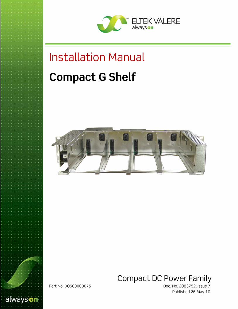
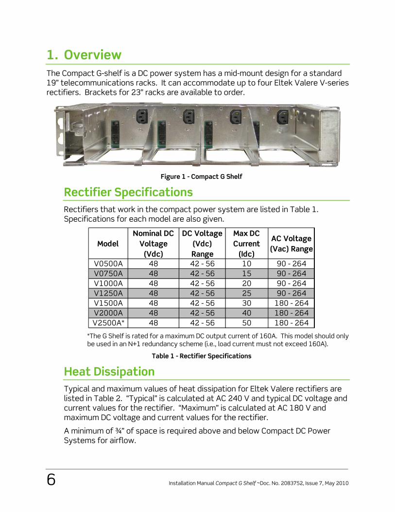
1. Overview The Compact G-shelf is a DC power system has a mid-mount design for a standard 19” telecommunications racks. It can accommodate up to four Eltek Valere V-series rectifiers. Brackets for 23” racks are available to order.
Figure 1 - Compact G Shelf
Rectifier Specifications Rectifiers that work in the compact power system are listed in Table 1. Specifications for each model are also given.
ModelNominal DC
Voltage (Vdc)
DC Voltage (Vdc) Range
Max DC Current
(Idc)
AC Voltage (Vac) Range
V0500A 48 42 - 56 10 90 - 264V0750A 48 42 - 56 15 90 - 264V1000A 48 42 - 56 20 90 - 264V1250A 48 42 - 56 25 90 - 264V1500A 48 42 - 56 30 180 - 264V2000A 48 42 - 56 40 180 - 264V2500A* 48 42 - 56 50 180 - 264
*The G Shelf is rated for a maximum DC output current of 160A. This model should only be used in an N+1 redundancy scheme (i.e., load current must not exceed 160A).
Table 1 - Rectifier Specifications
Heat Dissipation Typical and maximum values of heat dissipation for Eltek Valere rectifiers are listed in Table 2. “Typical” is calculated at AC 240 V and typical DC voltage and current values for the rectifier. “Maximum” is calculated at AC 180 V and maximum DC voltage and current values for the rectifier.
A minimum of ¾” of space is required above and below Compact DC Power Systems for airflow.
Installation Manual Compact G Shelf ~Doc. No. 2083752, Issue 7, May 2010 7
NOTICE: Heat dissipation greater than the objectives listed in GR-63-CORE may occur. Additional equipment room cooling may be required. To cope with high heat release, aisle spacing may be increased and high heat-dissipating equipment may be located adjacent to equipment generating less heat.
NOTICE: Values listed in the table are per rectifier rather than the sum of a fully-populated shelf.
Model 48 V Rectifiers BTU/hr Watts BTU/hr Watts
V0500A 180 53 281 82V0750A 271 79 435 127V1000A 361 106 563 165V1250A 451 132 690 202V1500A 541 159 844 247V2000A 722 212 1100 322V2500A 902 264 1355 397
Typical Maximum
Table 2 - Heat Dissipation
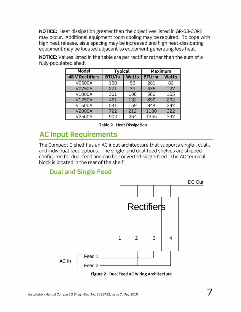
AC Input Requirements The Compact G shelf has an AC input architecture that supports single-, dual-, and individual-feed options. The single- and dual-feed shelves are shipped configured for dual-feed and can be converted single-feed. The AC terminal block is located in the rear of the shelf.
Dual and Single Feed
Rectifiers
1 2 3 4
Feed 1
Feed 2AC In
DC Out
Figure 2 - Dual Feed AC Wiring Architecture
8 Installation Manual Compact G Shelf ~Doc. No. 2083752, Issue 7, May 2010
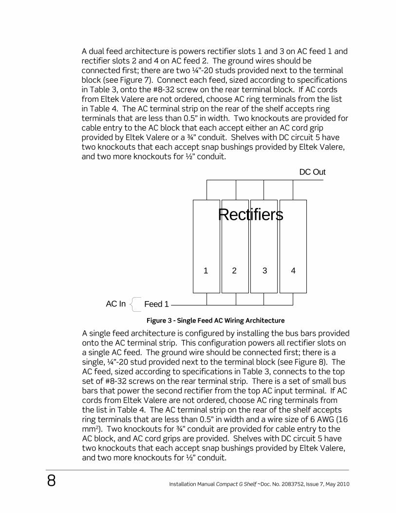
A dual feed architecture is powers rectifier slots 1 and 3 on AC feed 1 and rectifier slots 2 and 4 on AC feed 2. The ground wires should be connected first; there are two ¼”-20 studs provided next to the terminal block (see Figure 7). Connect each feed, sized according to specifications in Table 3, onto the #8-32 screw on the rear terminal block. If AC cords from Eltek Valere are not ordered, choose AC ring terminals from the list in Table 4. The AC terminal strip on the rear of the shelf accepts ring terminals that are less than 0.5” in width. Two knockouts are provided for cable entry to the AC block that each accept either an AC cord grip provided by Eltek Valere or a ¾” conduit. Shelves with DC circuit 5 have two knockouts that each accept snap bushings provided by Eltek Valere, and two more knockouts for ½” conduit.
Rectifiers
1 2 3 4
Feed 1AC In
DC Out
Figure 3 - Single Feed AC Wiring Architecture
A single feed architecture is configured by installing the bus bars provided onto the AC terminal strip. This configuration powers all rectifier slots on a single AC feed. The ground wire should be connected first; there is a single, ¼”-20 stud provided next to the terminal block (see Figure 8). The AC feed, sized according to specifications in Table 3, connects to the top set of #8-32 screws on the rear terminal strip. There is a set of small bus bars that power the second rectifier from the top AC input terminal. If AC cords from Eltek Valere are not ordered, choose AC ring terminals from the list in Table 4. The AC terminal strip on the rear of the shelf accepts ring terminals that are less than 0.5” in width and a wire size of 6 AWG (16 mm2). Two knockouts for ¾” conduit are provided for cable entry to the AC block, and AC cord grips are provided. Shelves with DC circuit 5 have two knockouts that each accept snap bushings provided by Eltek Valere, and two more knockouts for ½” conduit.
Installation Manual Compact G Shelf ~Doc. No. 2083752, Issue 7, May 2010 9
Individual Feed
Rectifiers
1 2 3 4
Feed 1
Feed 2Feed 3Feed 4
AC In
DC Out
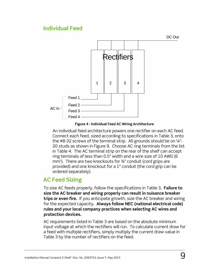
Figure 4 - Individual Feed AC Wiring Architecture
An individual feed architecture powers one rectifier on each AC feed. Connect each feed, sized according to specifications in Table 3, onto the #8-32 screws of the terminal strip. All grounds should be on ¼”-20 studs as shown in Figure 9. Choose AC ring terminals from the list in Table 4. The AC terminal strip on the rear of the shelf can accept ring terminals of less than 0.5” width and a wire size of 10 AWG (6 mm2). There are two knockouts for ¾” conduit (cord grips are provided) and one knockout for a 1” conduit (the cord grip can be ordered separately).
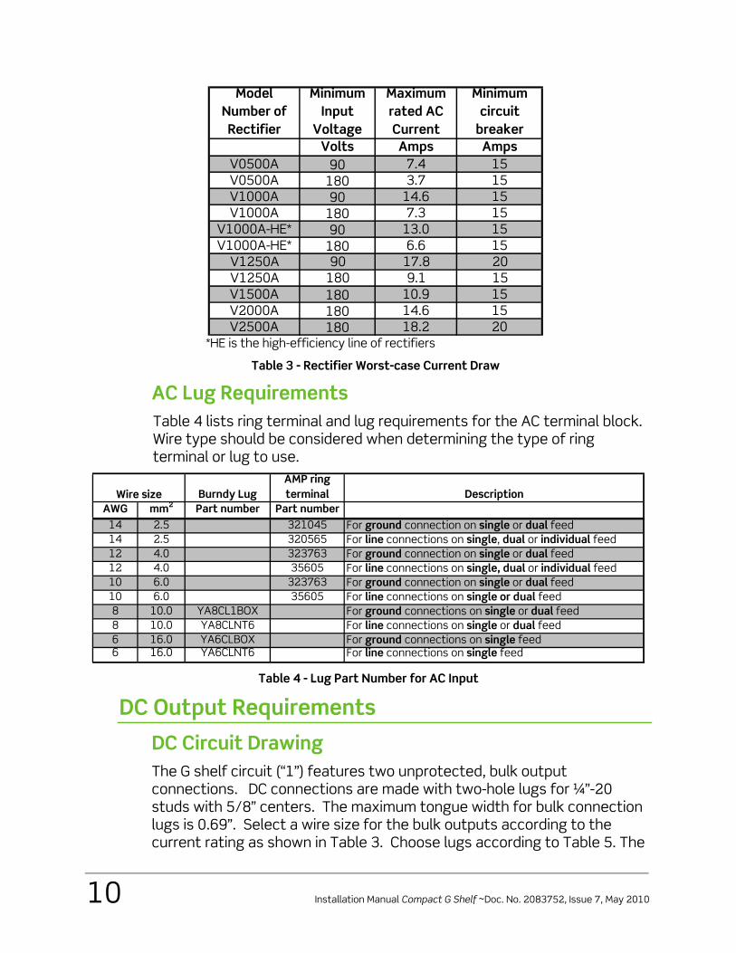
AC Feed Sizing To size AC feeds properly, follow the specifications in Table 3. Failure to size the AC breaker and wiring properly can result in nuisance breaker trips or even fire. If you anticipate growth, size the AC breaker and wiring for the expected capacity. Always follow NEC (national electrical code) rules and your local company practices when selecting AC wires and protection devices.
AC requirements listed in Table 3 are based on the absolute minimum input voltage at which the rectifiers will run. To calculate current draw for a feed with multiple rectifiers, simply multiply the current draw value in Table 3 by the number of rectifiers on the feed.
10 Installation Manual Compact G Shelf ~Doc. No. 2083752, Issue 7, May 2010
Model Number of Rectifier
Minimum Input
Voltage
Maximum rated AC Current
Minimum circuit
breakerVolts Amps Amps
V0500A 90 7.4 15V0500A 180 3.7 15V1000A 90 14.6 15V1000A 180 7.3 15
V1000A-HE* 90 13.0 15V1000A-HE* 180 6.6 15
V1250A 90 17.8 20V1250A 180 9.1 15V1500A 180 10.9 15V2000A 180 14.6 15V2500A 180 18.2 20
*HE is the high-efficiency line of rectifiers
Table 3 - Rectifier Worst-case Current Draw
AC Lug Requirements Table 4 lists ring terminal and lug requirements for the AC terminal block. Wire type should be considered when determining the type of ring terminal or lug to use.
Burndy LugAMP ring terminal Description
AWG mm2 Part number Part number14 2.5 321045 For ground connection on single or dual feed14 2.5 320565 For line connections on single, dual or individual feed12 4.0 323763 For ground connection on single or dual feed12 4.0 35605 For line connections on single, dual or individual feed10 6.0 323763 For ground connection on single or dual feed10 6.0 35605 For line connections on single or dual feed8 10.0 YA8CL1BOX For ground connections on single or dual feed8 10.0 YA8CLNT6 For line connections on single or dual feed6 16.0 YA6CLBOX For ground connections on single feed6 16.0 YA6CLNT6 For line connections on single feed
Wire size
Table 4 - Lug Part Number for AC Input
DC Output Requirements
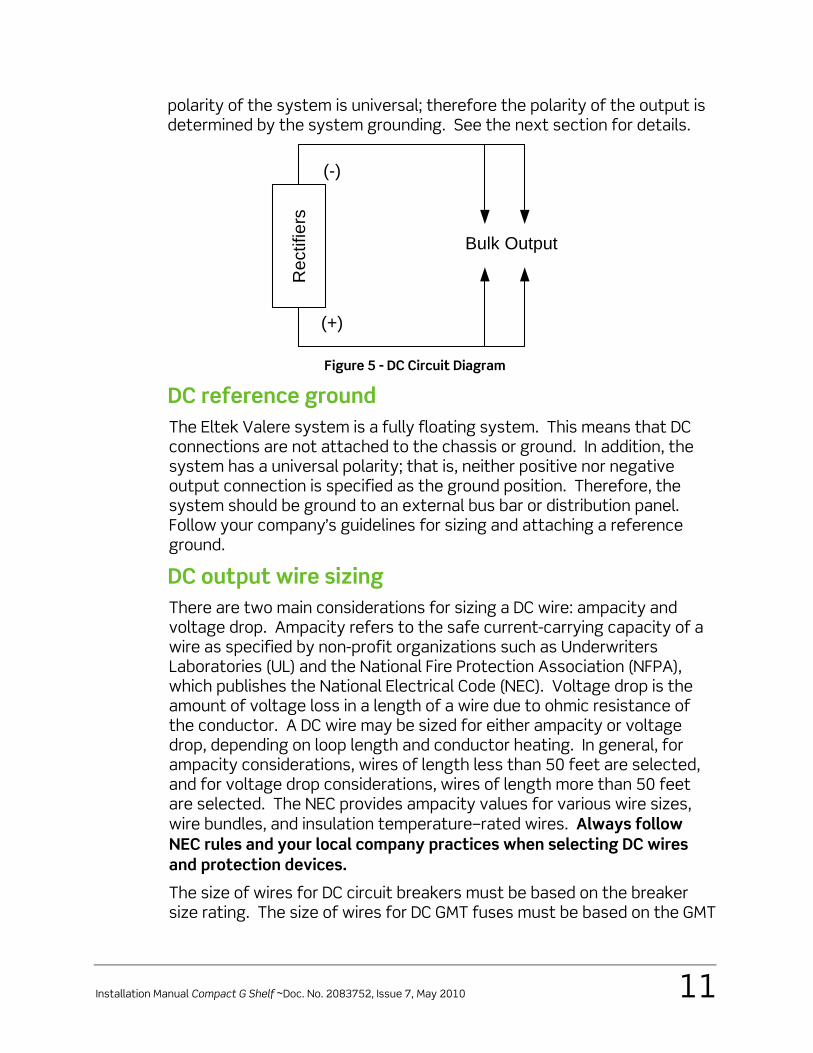
DC Circuit Drawing The G shelf circuit (“1”) features two unprotected, bulk output connections. DC connections are made with two-hole lugs for ¼”-20 studs with 5/8” centers. The maximum tongue width for bulk connection lugs is 0.69”. Select a wire size for the bulk outputs according to the current rating as shown in Table 3. Choose lugs according to Table 5. The
Installation Manual Compact G Shelf ~Doc. No. 2083752, Issue 7, May 2010 11
polarity of the system is universal; therefore the polarity of the output is determined by the system grounding. See the next section for details.
Rec
tifie
rs
Bulk Output
(-)
(+)
Figure 5 - DC Circuit Diagram
DC reference ground The Eltek Valere system is a fully floating system. This means that DC connections are not attached to the chassis or ground. In addition, the system has a universal polarity; that is, neither positive nor negative output connection is specified as the ground position. Therefore, the system should be ground to an external bus bar or distribution panel. Follow your company’s guidelines for sizing and attaching a reference ground.
DC output wire sizing There are two main considerations for sizing a DC wire: ampacity and voltage drop. Ampacity refers to the safe current-carrying capacity of a wire as specified by non-profit organizations such as Underwriters Laboratories (UL) and the National Fire Protection Association (NFPA), which publishes the National Electrical Code (NEC). Voltage drop is the amount of voltage loss in a length of a wire due to ohmic resistance of the conductor. A DC wire may be sized for either ampacity or voltage drop, depending on loop length and conductor heating. In general, for ampacity considerations, wires of length less than 50 feet are selected, and for voltage drop considerations, wires of length more than 50 feet are selected. The NEC provides ampacity values for various wire sizes, wire bundles, and insulation temperature–rated wires. Always follow NEC rules and your local company practices when selecting DC wires and protection devices.
The size of wires for DC circuit breakers must be based on the breaker size rating. The size of wires for DC GMT fuses must be based on the GMT
12 Installation Manual Compact G Shelf ~Doc. No. 2083752, Issue 7, May 2010
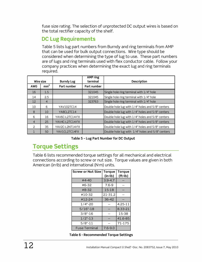
fuse size rating. The selection of unprotected DC output wires is based on the total rectifier capacity of the shelf.
DC Lug Requirements Table 5 lists lug part numbers from Burndy and ring terminals from AMP that can be used for bulk output connections. Wire type should be considered when determining the type of lug to use. These part numbers are of lugs and ring terminals used with flex conductor cable. Follow your company practices when determining the exact lug and ring terminals required.
Burndy LugAMP ring terminal Description
AWG mm2 Part number Part number
16 1.5 321045 Single hole ring terminal with 1/4" hole
14 2.5 321045 Single hole ring terminal with 1/4" hole12 4 323763 Single hole ring terminal with 1/4" hole
10 6 YAV102TC14 Double hole lug with 1/4" holes and 5/8" centers
8 10 YA8CL2TC14 Double hole lug with 1/4" holes and 5/8" centers
6 16 YAV6C-L2TC14-FX Double hole lug with 1/4" holes and 5/8" centers
4 25 YAV4C-L2TC14-FX Double hole lug with 1/4" holes and 5/8" centers
2 35 YAV2C-L2NT14-FX Double hole lug with 1/4" holes and 5/8" centers
1 50 YAV1CL2TC14FX Double hole lug with 1/4" holes and 5/8" centers
Wire size
Table 5 – Lug Part Number for DC Output
Torque Settings Table 6 lists recommended torque settings for all mechanical and electrical connections according to screw or nut size. Torque values are given in both American (in·lb) and international (N·m) units.
Screw or Nut Size Torque(in-lb)
Torque(ft-lb)
#4-40 3.9-4.7 --
#6-32 7.6-9 --
#8-32 15-18 --
#10-32 21-31.2 --
#12-24 36-42 --
1/4"-20 -- 4.25-11
5/16"-18 -- 8.33-21
3/8"-16 -- 15-38
1/2"-13 -- 41.6-85
5/8"-11 -- 71-175
Fuse Terminal 7.6-9.0 Table 6 - Recommended Torque Settings
Installation Manual Compact G Shelf ~Doc. No. 2083752, Issue 7, May 2010 13
Required Tools The power system is designed to be installed with a minimum number of commonly available tools.
o #1 and #2 Phillips screwdrivers
o Torque wrench
o 5/16” and 7/16” box wrenches, sockets, and nut drivers
o Wire and cable strippers
o Wire and cable crimpers
14 Installation Manual Compact G Shelf ~Doc. No. 2083752, Issue 7, May 2010
2. Installation Before installing the power system the following safety requirements should be considered.
o Elevated Operating Ambient: If installed in a closed or multi-unit rack assembly, the operating ambient temperature of the rack environment may be greater than room ambient. Therefore, consideration should be given to installing the equipment in an environment compatible with the maximum ambient temperature (Tma) specified by the manufacturer.
o Reduced Air Flow: Installation of the equipment in a rack should be such that the amount of air flow required for safe operation of the equipment is not compromised.
o Mechanical Loading: Mounting of the equipment in the rack should be such that a hazardous condition is not achieved due to uneven mechanical loading.
o Circuit Overloading: Consideration should be given to the connection of the equipment to the supply circuit and the effect that overloading of the circuits might have on over-current protection and supply wiring. Appropriate consideration of equipment nameplate ratings should be used when addressing this concern.
o Reliable Earthing: Reliable earthing of rack-mounted equipment should be maintained. Particular attention should be given to supply connections other than direct connections to the branch circuit (e.g. use of power strips).
Site Preparation Before unpacking the DC power system, note any physical package damage that could indicate potential damage to the contents. After removing the system from boxes and packing material, inspect for any shipping or other damage. Contact sales or technical support immediately if you notice any damage.
Have all tools, wires, cables, hardware, and so on within easy reach. To the extent possible, ensure a clean (free of debris, dust, and foreign material) work environment. Care should be taken during the installation process to prevent exposure of the equipment to wire clippings. If possible, rectifiers should remained sealed in their shipping boxes until the shelf wiring is complete. Ensure that all AC and DC power sources are off and disconnected.
Installation Manual Compact G Shelf ~Doc. No. 2083752, Issue 7, May 2010 15
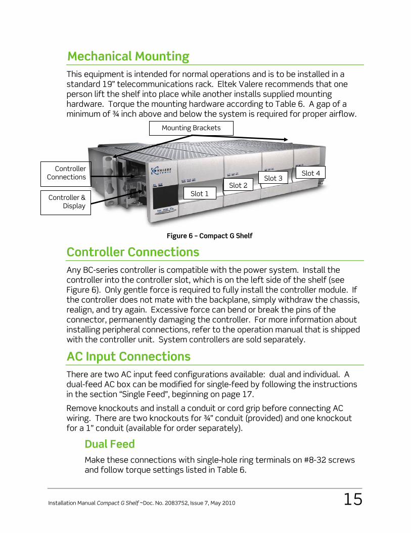
Mechanical Mounting This equipment is intended for normal operations and is to be installed in a standard 19” telecommunications rack. Eltek Valere recommends that one person lift the shelf into place while another installs supplied mounting hardware. Torque the mounting hardware according to Table 6. A gap of a minimum of ¾ inch above and below the system is required for proper airflow.
Figure 6 – Compact G Shelf
Controller Connections Any BC-series controller is compatible with the power system. Install the controller into the controller slot, which is on the left side of the shelf (see Figure 6). Only gentle force is required to fully install the controller module. If the controller does not mate with the backplane, simply withdraw the chassis, realign, and try again. Excessive force can bend or break the pins of the connector, permanently damaging the controller. For more information about installing peripheral connections, refer to the operation manual that is shipped with the controller unit. System controllers are sold separately.
AC Input Connections There are two AC input feed configurations available: dual and individual. A dual-feed AC box can be modified for single-feed by following the instructions in the section “Single Feed”, beginning on page 17.
Remove knockouts and install a conduit or cord grip before connecting AC wiring. There are two knockouts for ¾” conduit (provided) and one knockout for a 1” conduit (available for order separately).
Dual Feed Make these connections with single-hole ring terminals on #8-32 screws and follow torque settings listed in Table 6.
Controller Connections
Controller & Display
Slot 1Slot 2
Slot 3Slot 4
Mounting Brackets
16 Installation Manual Compact G Shelf ~Doc. No. 2083752, Issue 7, May 2010
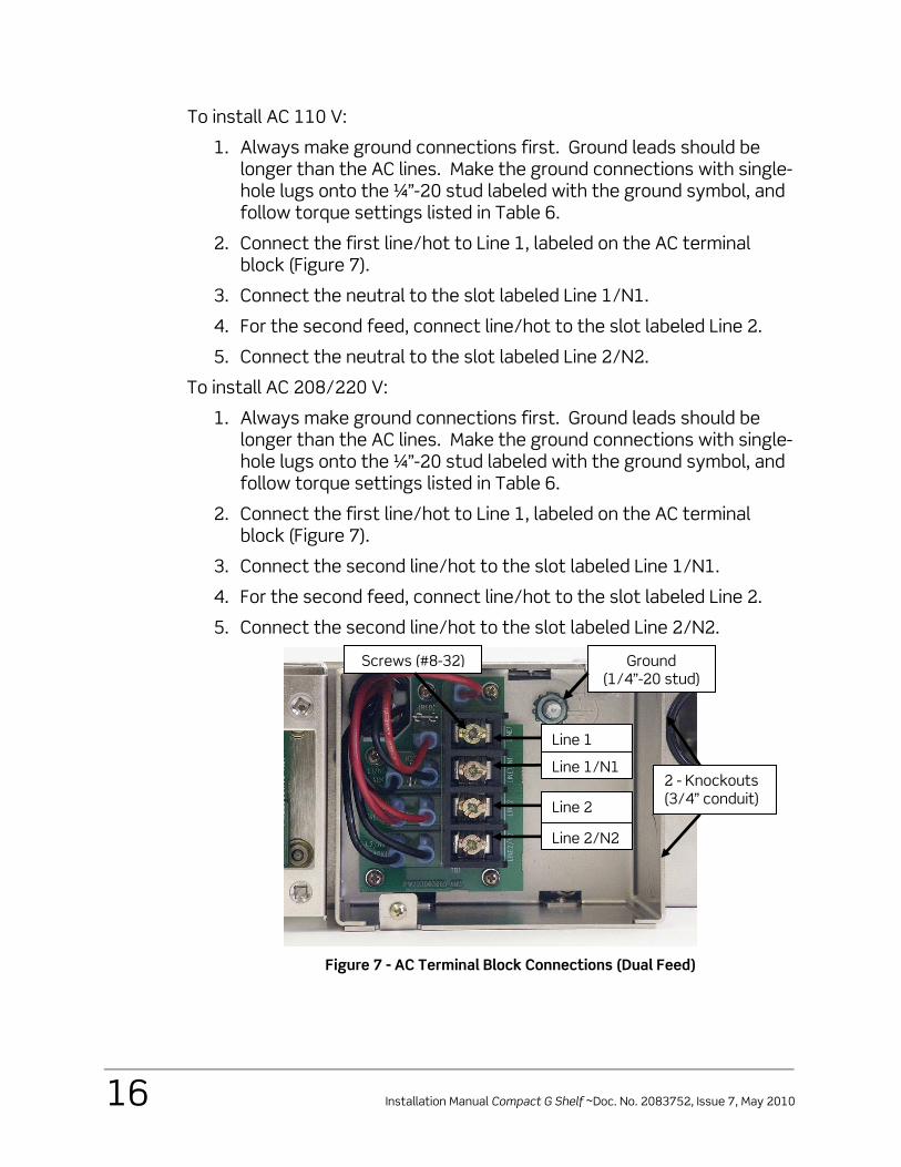
To install AC 110 V:
1. Always make ground connections first. Ground leads should be longer than the AC lines. Make the ground connections with single-hole lugs onto the ¼”-20 stud labeled with the ground symbol, and follow torque settings listed in Table 6.
2. Connect the first line/hot to Line 1, labeled on the AC terminal block (Figure 7).
3. Connect the neutral to the slot labeled Line 1/N1.
4. For the second feed, connect line/hot to the slot labeled Line 2.
5. Connect the neutral to the slot labeled Line 2/N2.
To install AC 208/220 V:
1. Always make ground connections first. Ground leads should be longer than the AC lines. Make the ground connections with single-hole lugs onto the ¼”-20 stud labeled with the ground symbol, and follow torque settings listed in Table 6.
2. Connect the first line/hot to Line 1, labeled on the AC terminal block (Figure 7).
3. Connect the second line/hot to the slot labeled Line 1/N1.
4. For the second feed, connect line/hot to the slot labeled Line 2.
5. Connect the second line/hot to the slot labeled Line 2/N2.
Figure 7 - AC Terminal Block Connections (Dual Feed)
Ground (1/4”-20 stud)
Screws (#8-32)
Line 1
Line 1/N1
Line 2
Line 2/N2
2 - Knockouts(3/4” conduit)
Installation Manual Compact G Shelf ~Doc. No. 2083752, Issue 7, May 2010 17
Single Feed To convert a dual feed box to single feed, install the terminal straps provided. The straps are small bus bars (part numbers B0247011513 and B0247011512) that, when installed, allow all rectifier slots to be fed by a single AC input.
WARNING: AC breaker and wire sizing must be adjusted for a single AC input feed.
WARNING: Once the bus bar straps are added only one AC feed can be connected to the power shelf. DO NOT attempt to connect a second feed in parallel.
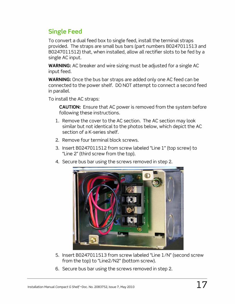
To install the AC straps:
CAUTION: Ensure that AC power is removed from the system before following these instructions.
1. Remove the cover to the AC section. The AC section may look similar but not identical to the photos below, which depict the AC section of a K-series shelf.
2. Remove four terminal block screws.
3. Insert B0247011512 from screw labeled “Line 1” (top screw) to “Line 2” (third screw from the top).
4. Secure bus bar using the screws removed in step 2.
5. Insert B0247011513 from screw labeled “Line 1/N” (second screw
from the top) to “Line2/N2” (bottom screw).
6. Secure bus bar using the screws removed in step 2.
18 Installation Manual Compact G Shelf ~Doc. No. 2083752, Issue 7, May 2010
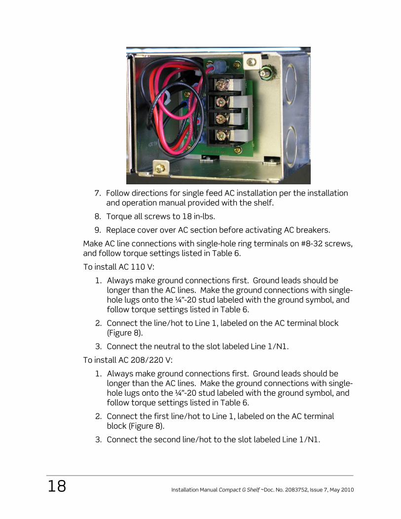
7. Follow directions for single feed AC installation per the installation
and operation manual provided with the shelf.
8. Torque all screws to 18 in-lbs.
9. Replace cover over AC section before activating AC breakers.
Make AC line connections with single-hole ring terminals on #8-32 screws, and follow torque settings listed in Table 6.
To install AC 110 V:
1. Always make ground connections first. Ground leads should be longer than the AC lines. Make the ground connections with single-hole lugs onto the ¼”-20 stud labeled with the ground symbol, and follow torque settings listed in Table 6.
2. Connect the line/hot to Line 1, labeled on the AC terminal block (Figure 8).
3. Connect the neutral to the slot labeled Line 1/N1.
To install AC 208/220 V:
1. Always make ground connections first. Ground leads should be longer than the AC lines. Make the ground connections with single-hole lugs onto the ¼”-20 stud labeled with the ground symbol, and follow torque settings listed in Table 6.
2. Connect the first line/hot to Line 1, labeled on the AC terminal block (Figure 8).
3. Connect the second line/hot to the slot labeled Line 1/N1.
Installation Manual Compact G Shelf ~Doc. No. 2083752, Issue 7, May 2010 19
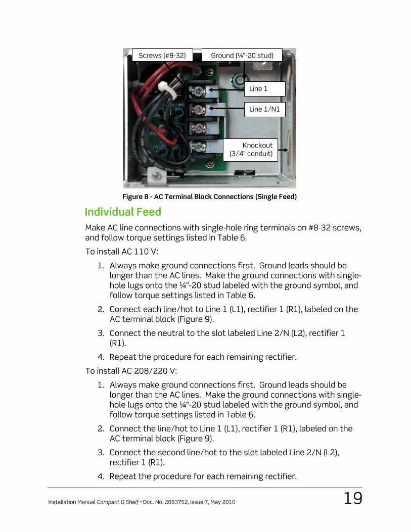
Figure 8 - AC Terminal Block Connections (Single Feed)
Individual Feed Make AC line connections with single-hole ring terminals on #8-32 screws, and follow torque settings listed in Table 6.
To install AC 110 V:
1. Always make ground connections first. Ground leads should be longer than the AC lines. Make the ground connections with single-hole lugs onto the ¼”-20 stud labeled with the ground symbol, and follow torque settings listed in Table 6.
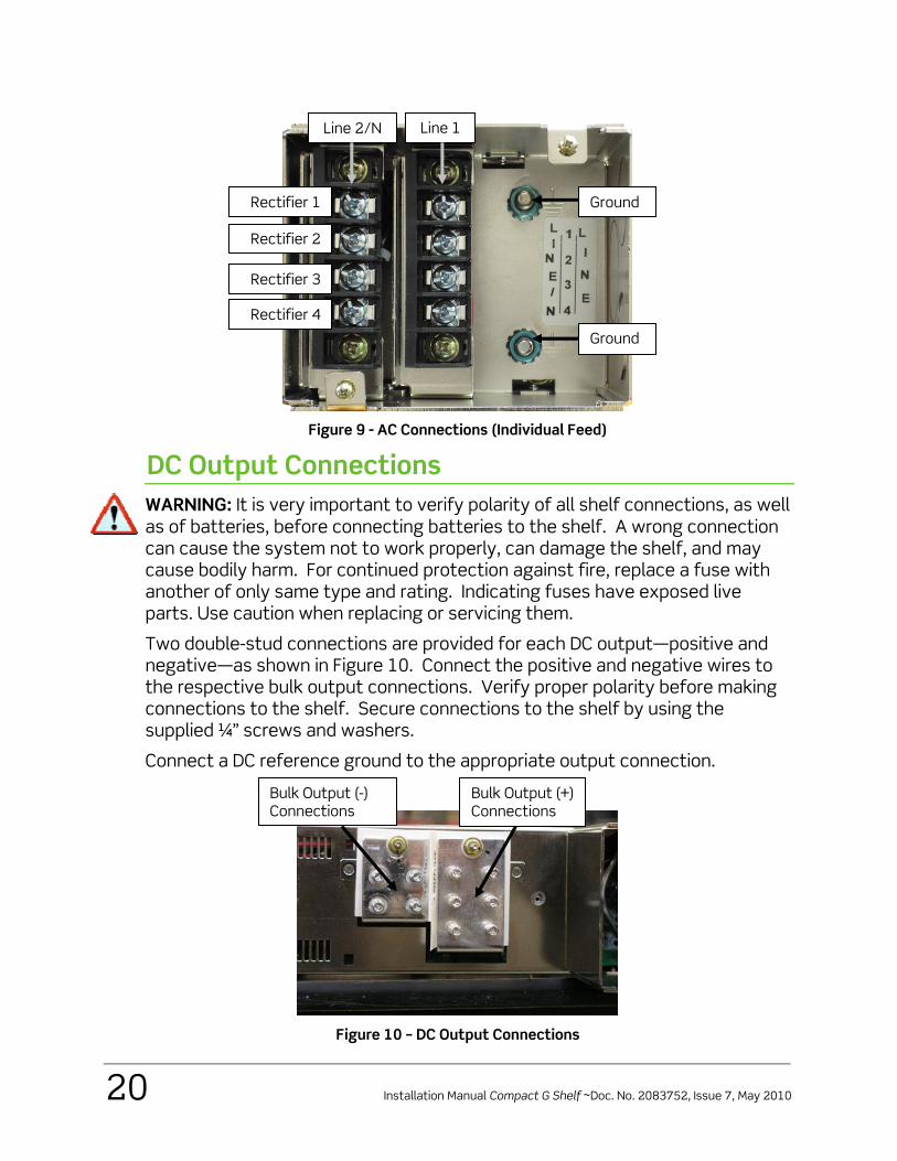
2. Connect each line/hot to Line 1 (L1), rectifier 1 (R1), labeled on the AC terminal block (Figure 9).
3. Connect the neutral to the slot labeled Line 2/N (L2), rectifier 1 (R1).
4. Repeat the procedure for each remaining rectifier.
To install AC 208/220 V:
1. Always make ground connections first. Ground leads should be longer than the AC lines. Make the ground connections with single-hole lugs onto the ¼”-20 stud labeled with the ground symbol, and follow torque settings listed in Table 6.
2. Connect the line/hot to Line 1 (L1), rectifier 1 (R1), labeled on the AC terminal block (Figure 9).
3. Connect the second line/hot to the slot labeled Line 2/N (L2), rectifier 1 (R1).
4. Repeat the procedure for each remaining rectifier.
Line 1
Line 1/N1
Knockout(3/4” conduit)
Ground (¼”-20 stud)Screws (#8-32)
20 Installation Manual Compact G Shelf ~Doc. No. 2083752, Issue 7, May 2010
Figure 9 - AC Connections (Individual Feed)
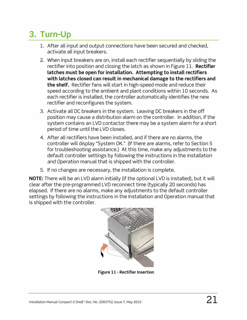
DC Output Connections WARNING: It is very important to verify polarity of all shelf connections, as well as of batteries, before connecting batteries to the shelf. A wrong connection can cause the system not to work properly, can damage the shelf, and may cause bodily harm. For continued protection against fire, replace a fuse with another of only same type and rating. Indicating fuses have exposed live parts. Use caution when replacing or servicing them.
Two double-stud connections are provided for each DC output—positive and negative—as shown in Figure 10. Connect the positive and negative wires to the respective bulk output connections. Verify proper polarity before making connections to the shelf. Secure connections to the shelf by using the supplied ¼” screws and washers.
Connect a DC reference ground to the appropriate output connection.
Figure 10 – DC Output Connections
Bulk Output (+) Connections
Bulk Output (-) Connections
Rectifier 1
Rectifier 2
Rectifier 3
Line 2/N Line 1
Ground
Ground
Rectifier 4
Installation Manual Compact G Shelf ~Doc. No. 2083752, Issue 7, May 2010 21
3. Turn-Up 1. After all input and output connections have been secured and checked,
activate all input breakers.
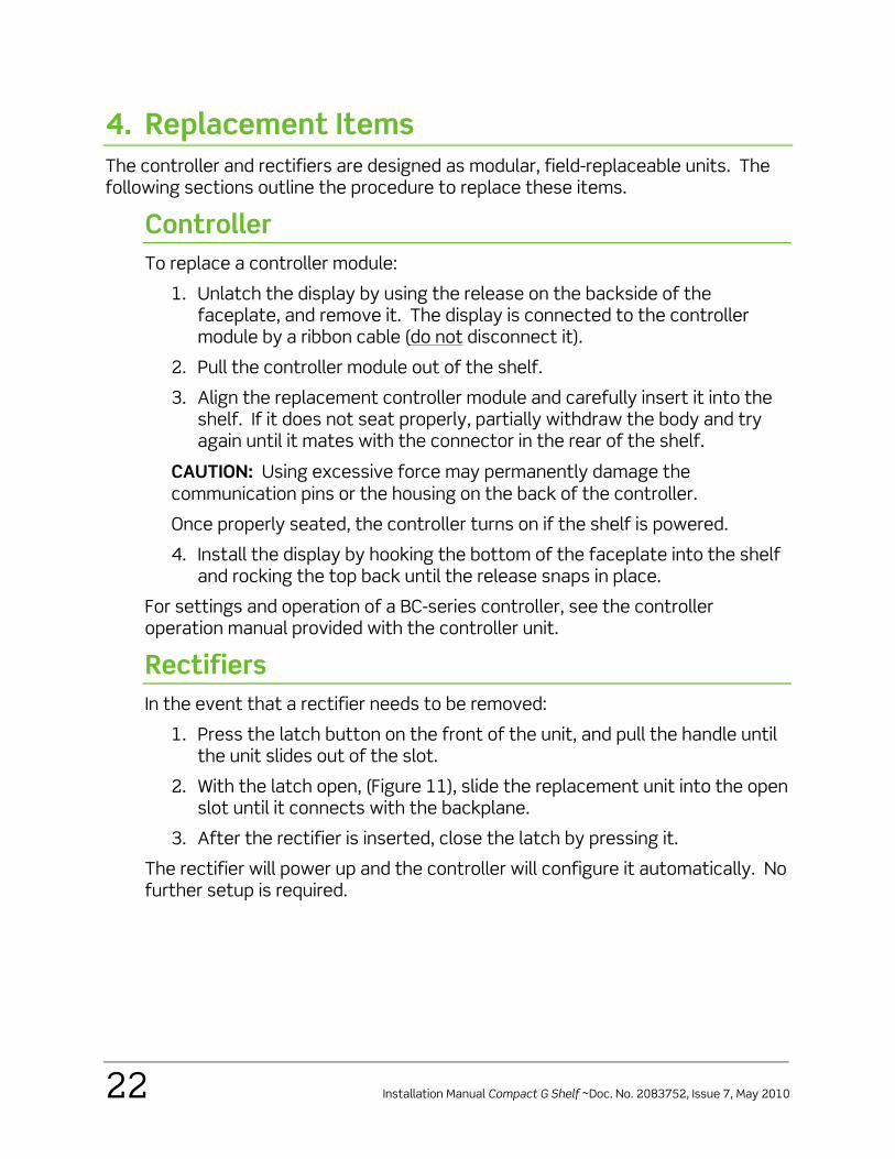
2. When input breakers are on, install each rectifier sequentially by sliding the rectifier into position and closing the latch as shown in Figure 11. Rectifier latches must be open for installation. Attempting to install rectifiers with latches closed can result in mechanical damage to the rectifiers and the shelf. Rectifier fans will start in high-speed mode and reduce their speed according to the ambient and plant conditions within 10 seconds. As each rectifier is installed, the controller automatically identifies the new rectifier and reconfigures the system.
3. Activate all DC breakers in the system. Leaving DC breakers in the off position may cause a distribution alarm on the controller. In addition, if the system contains an LVD contactor there may be a system alarm for a short period of time until the LVD closes.
4. After all rectifiers have been installed, and if there are no alarms, the controller will display “System OK.” (If there are alarms, refer to Section 5 for troubleshooting assistance.) At this time, make any adjustments to the default controller settings by following the instructions in the Installation and Operation manual that is shipped with the controller.
5. If no changes are necessary, the installation is complete.
NOTE: There will be an LVD alarm initially (if the optional LVD is installed), but it will clear after the pre-programmed LVD reconnect time (typically 20 seconds) has elapsed. If there are no alarms, make any adjustments to the default controller settings by following the instructions in the Installation and Operation manual that is shipped with the controller.
Figure 11 - Rectifier Insertion
22 Installation Manual Compact G Shelf ~Doc. No. 2083752, Issue 7, May 2010
4. Replacement Items The controller and rectifiers are designed as modular, field-replaceable units. The following sections outline the procedure to replace these items.
Controller To replace a controller module:
1. Unlatch the display by using the release on the backside of the faceplate, and remove it. The display is connected to the controller module by a ribbon cable (do not disconnect it).
2. Pull the controller module out of the shelf.
3. Align the replacement controller module and carefully insert it into the shelf. If it does not seat properly, partially withdraw the body and try again until it mates with the connector in the rear of the shelf.
CAUTION: Using excessive force may permanently damage the communication pins or the housing on the back of the controller.
Once properly seated, the controller turns on if the shelf is powered.
4. Install the display by hooking the bottom of the faceplate into the shelf and rocking the top back until the release snaps in place.
For settings and operation of a BC-series controller, see the controller operation manual provided with the controller unit.
Rectifiers In the event that a rectifier needs to be removed:
1. Press the latch button on the front of the unit, and pull the handle until the unit slides out of the slot.
2. With the latch open, (Figure 11), slide the replacement unit into the open slot until it connects with the backplane.
3. After the rectifier is inserted, close the latch by pressing it.
The rectifier will power up and the controller will configure it automatically. No further setup is required.
Installation Manual Compact G Shelf ~Doc. No. 2083752, Issue 7, May 2010 23
5. Troubleshooting
Problems and Solutions In case of an alarm from the controller, verify the following (for details, refer to the Controller Installation and Operation manual):
o All AC and DC connections are secured properly.
o All rectifiers are installed and seated properly.
o The controller is installed and seated properly.
Follow these instructions for different scenarios:
o AC OK off, DC OK off, ALM on or off, and display blank: Verify that proper AC voltage has been supplied to the rectifiers being used. Refer to Table 1 for AC input voltage requirements. Reseat the rectifiers, and if problems continue, replace the rectifiers.
o AC OK on, DC OK off, ALM LED on, and display blank: Check DC output connections for any short circuit. Reseat the rectifiers, and if problems continue, replace the rectifiers.
o AC OK on, DC OK on, and display blank: For details about troubleshooting in this scenario, refer to the Controller Installation and Operation manual.
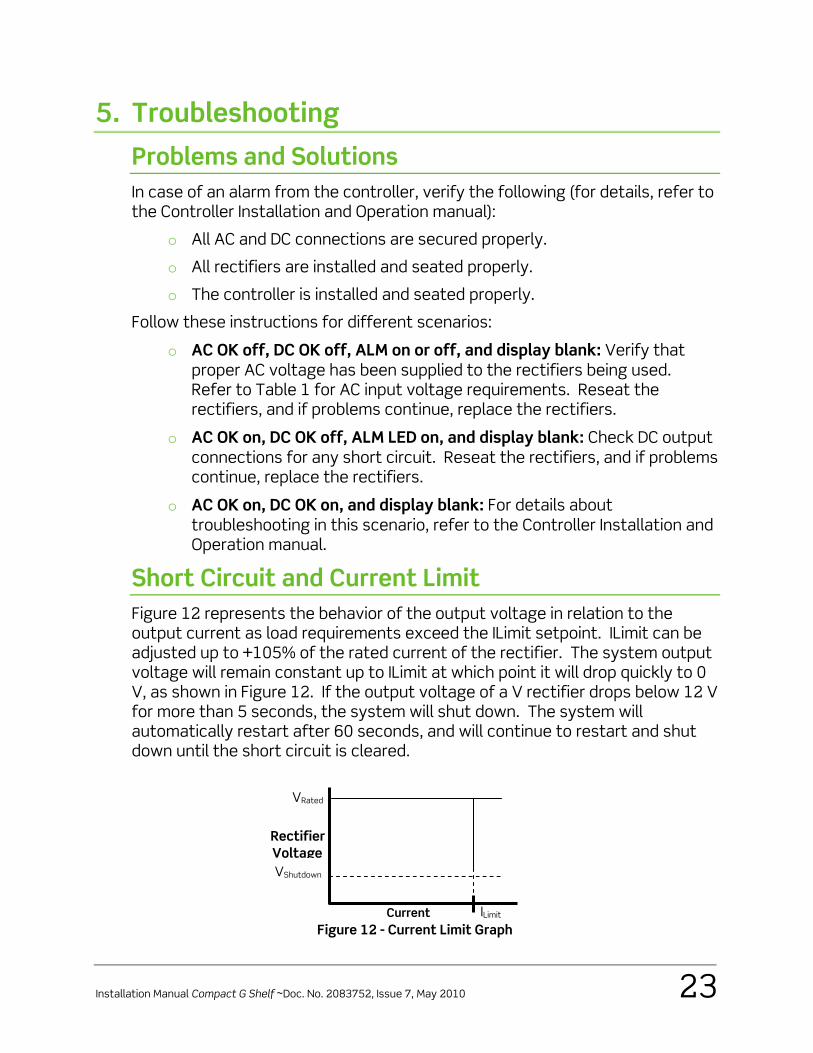
Short Circuit and Current Limit Figure 12 represents the behavior of the output voltage in relation to the output current as load requirements exceed the ILimit setpoint. ILimit can be adjusted up to +105% of the rated current of the rectifier. The system output voltage will remain constant up to ILimit at which point it will drop quickly to 0 V, as shown in Figure 12. If the output voltage of a V rectifier drops below 12 V for more than 5 seconds, the system will shut down. The system will automatically restart after 60 seconds, and will continue to restart and shut down until the short circuit is cleared.
Figure 12 - Current Limit Graph
ILimitCurrent
VRated
Rectifier Voltage VShutdown
24 Installation Manual Compact G Shelf ~Doc. No. 2083752, Issue 7, May 2010
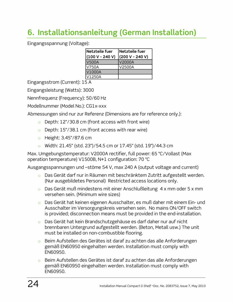
6. Installationsanleitung (German Installation) Eingangsspannung (Voltage):
Netzteile fuer (100 V – 240 V)
Netzteile fuer (200 V – 240 V)
V500A V2000AV750A V2500AV1000AV1250A
Eingangsstrom (Current): 15 A
Eingangsleistung (Watts): 3000
Nennfrequenz (Frequency): 50/60 Hz
Modellnummer (Model No.): CG1x-xxx
Abmessungen sind nur zur Referenz (Dimensions are for reference only.):
o Depth: 12”/30.8 cm (front access with front wire)
o Depth: 15”/38.1 cm (front access with rear wire)
o Height: 3.45”/87.6 cm
o Width: 21.45” (std. 23”)/54.5 cm or 17.45” (std. 19”)/44.3 cm
Max. Umgebungstemperatur: V2000A rectifier, full power: 65 °C/Vollast (Max operation temperature) V1500B, N+1 configuration: 70 °C
Ausgangsspannungen und –stöme 54 V, max 240 A (output voltage and current)
o Das Gerät darf nur in Räumen mit beschränktem Zutritt aufgestellt werden. (Nur ausgebildetes Personal) Restricted access locations only.
o Das Gerät muß mindestens mit einer Anschlußleitung 4 x mm oder 5 x mm versehen sein. (Minimum wire sizes)
o Das Gerät hat keinen eigenen Ausschalter, es muß daher mit einem Ein- und Ausschalter im Versorgungskreis versehen sein. No mains ON/OFF switch is provided; disconnection means must be provided in the end-installation.
o Das Gerät hat kein Brandschutzgehäuse es darf daher nur auf nicht brennbaren Untergrund aufgestellt werden. (Beton, Metall usw.) The unit must be installed on non-combustible flooring.
o Beim Aufstellen des Gerätes ist daraf zu achten das alle Anforderungen gemäß EN60950 eingehalten werden. Installation must comply with EN60950.
o Beim Aufstellen des Gerätes ist daraf zu achten das alle Anforderungen gemäß EN60950 eingehalten werden. Installation must comply with EN60950.
Installation Manual Compact G Shelf ~Doc. No. 2083752, Issue 7, May 2010 25
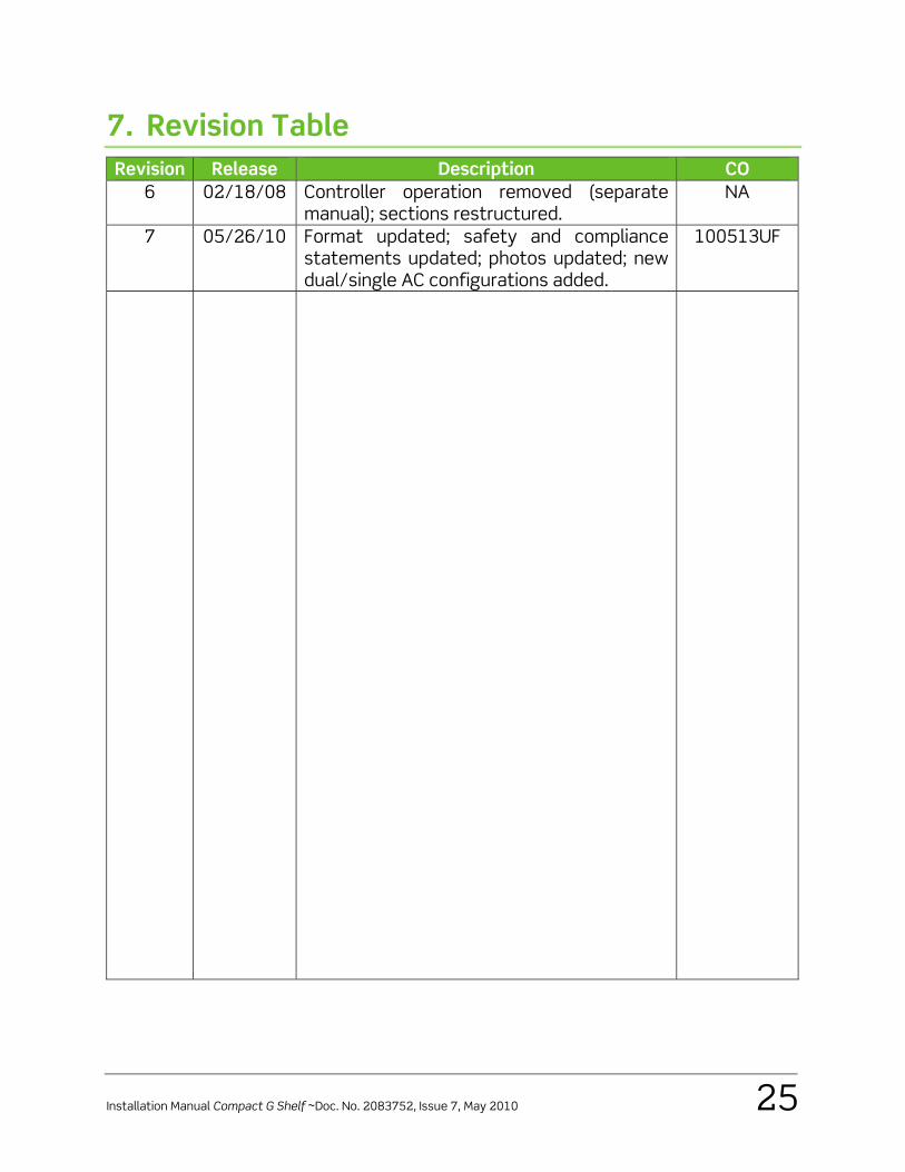
7. Revision Table Revision Release Description CO
6 02/18/08 Controller operation removed (separate manual); sections restructured.
NA
7 05/26/10 Format updated; safety and compliance statements updated; photos updated; new dual/single AC configurations added.
100513UF

Doc. No. 2083752, Issue 7 Published 26-May-10
www.eltekvalere.com Headquarters: Eltek Valere 1303 E. Arapaho Rd, Richardson, TX. 75081, USA Phone: +1 (469) 330-9100 Fax: +1 (469) 330-9101
Eltek Valere
Gråterudv. 8, Pb 2340 Strømsø, 3003 Drammen, Norway Phone: +47 32 20 32 00 Fax: +47 32 20 32 10