Embed Size (px)
Citation preview
Ver 4.0
Installation Manual
D6M_HxA Series : D6M_H3A / D6M_H4A / D7M_H7A / D7M_H8A
D6P_HxA Series : D7P_H7A / D7P_H8A D6K_HxA Series : D6K_H3A / D6K_H4A
This manual is for URE photovoltaic modules listed above
For more information, please visit us at www.UREcorp.com ----------------------------------------------------------------
Contact us Headquarters: 7, Li-Hsin 3rd Rd., Hsinchu Science Park, Hsinchu, 30078, Taiwan
Tel: +886 3 578 0011 Fax: +886 3 578 1255 E-mail: [email protected]
1 Ver. 2.0
Content
General information
Safety precaution for the installing solar PV system
Fire safety
Mechanical installation
Electrical installation
Commission & Maintenance
Disclaimer of Liability
2
2
3
4
9
13
13
2 Ver. 2.0
General Information This manual contains information regarding the installation and safe handling of URE photovoltaic (PV)
modules. All instructions should be read and understood before attempting to install. If there are any
questions, please contact your dealer or URE for further information. The installer should conform to all
safety precautions in the manual when installing modules. Before installing a PV system, the installer should
become familiar with mechanical and electrical requirement for the PV system. All installations must be
performed in compliance with all applicable regional and local codes or other national and international
electrical standards. Keep this manual in a safe place for future reference.
Safety Precaution for Installing Solar PV System
- URE modules are qualified for Application Class A: Hazardous voltage (greater than 50 V DC) or
hazardous power applications (greater than 240 W), where general contact access is anticipated.
Modules qualified for safety under IEC 61730-1, IEC 61730-2 and within this application class are
considered to meet the requirements for Safety Class II.
- Installing PV systems should be performed only by qualified or licensed experts.
- Ensure that the URE modules are fastened to proper mounting systems designed for appropriate
mechanical loads resulting from wind and snow, and the proper weight of the modules.
- It is suggested that completely cover the module with an opaque material during installation to keep
electricity from being generated.
- Be very careful when disconnecting wires connected to PV modules that are exposed to sunlight, an
electric arc may result. Such arcs may cause burns, may start fires and may create problems.
- Artificially concentrated sunlight shall not be directed on the module or panel.
- PV module product operating temperature is from -40°C to 40°C
- Use only insulated tools that are approved for working on electrical installations.
- Routine maintenance of module shall not involve breaking or disturbing the bonding path.
- All of installation and handling activities must be carried out with due care, all collisions must be
avoided.
- Lift pallets by a fork lifter by a minimum of 70% of pallet length when loading and unloading from the
length side of a pallet; and 100% of pallet width when loading and unloading from the width side of a
pallet.
- Do not attempt to disassemble the module or remove any part of module.
- Do not remove the attached nameplate or components.
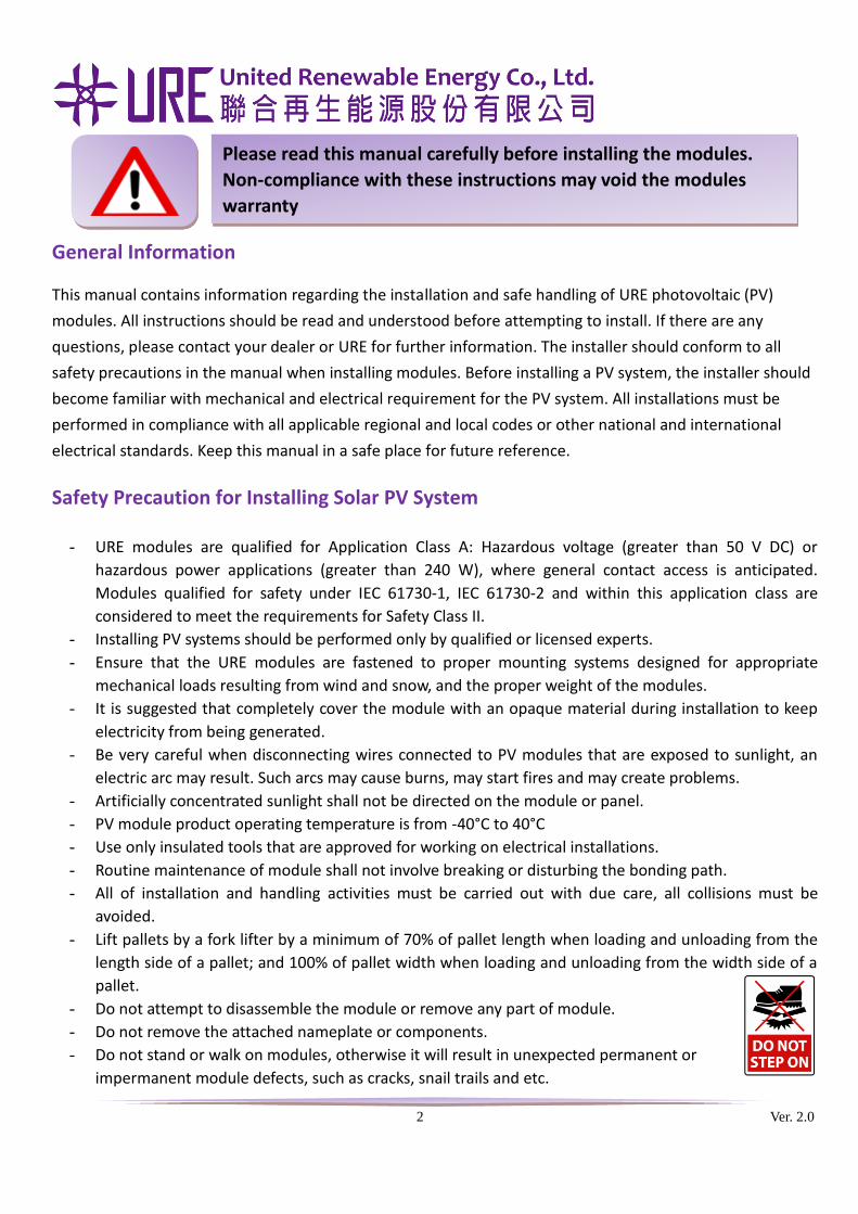
- Do not stand or walk on modules, otherwise it will result in unexpected permanent or
impermanent module defects, such as cracks, snail trails and etc.
Please read this manual carefully before installing the modules.
Non-compliance with these instructions may void the modules
warranty
3 Ver. 2.0
• It is recommended to reserve a service walkway when designing the solar PV system
- Do not place heavy objects on modules.
- Do not drop sharp objects on modules.
- Do not lift or transport modules by grasping the junction box or electrical leads.
- Do not drop the module down hard on any surface.
- Do not perform any work if the cables, connectors or junction box are wet due to the risk of electrical
shock.
- Do not work in rain, snow or windy conditions.
- Under normal conditions, a photovoltaic module is likely to experience conditions that produce more
current and/or voltage than reported at standard test conditions. Accordingly, the values of Isc and Voc
marked on this module should be multiplied by a factor of 1.25 when determining component voltage
ratings, conductor capacities, fuse sizes, and size of controls connected to the PV output. For example,
a safety factor for Voc and Isc of 1.25 is recommended since irradiance is often higher than 1000 W/m2
and temperature below 25°C may raise Voc. Refer to Section 690-8 of the National Electrical Code of an
additional multiplying factor of 125 percent (80 percent de-rating) which may be applicable.
Fire Safety
- URE modules are tested for fire safety based on its construction according to UL 790 standard. The fire
rating of this module is valid only when mounted in the manner specified in the mechanical mounting
instructions.
- To use components such as earth ground fault circuit breakers, fuses and circuit breakers as required
by local authority in the PV system for fire prevention.
- The fire safety of building may be affected by the roof construction and installations. Improper
installation may cause hazards in the event of fire.
- Consult with local authority for guidelines and requirements for building or structural fire safety.
- For roof installation, PV modules should be mounted over a fire resistant roof covering which is rated
for the application.
- Since sparks may be produced, do not install modules near equipment or locations where flammable
gases can be generated or collected.
- In case of fire, URE modules on the roof are likely to produce dangerous DC voltage and may have
potential hazard, even in the case of:
• Low light intensity
• Modules being disconnected from the inverter
• Modules being partly or entirely destroyed
4 Ver. 2.0
- When fire has been extinguished or for the duration of fire, stays away from all elements of the PV
system. Have your installer perform the necessary steps to bring the PV system back into a safe
condition.
Mechanical Installation
- The design and installation of photovoltaic systems shall be in accordance with the National Electrical
Code (NEC), the Canadian Electrical Code (CEC) and the national regulation of the country where the
modules will be installed.
- To install the modules in proper direction such as facing south in northern latitudes and north in
southern latitudes for best power output.
- Please note that any shadows cast by the modules do not fall on other modules behind them. This can
have adverse effects on overall system performance or may result in permanent damage to modules.
- PV module should be installed no higher than 2,000 m altitude. The modules should not be shaded at
any time. If the shade occurred on module surface, it will result in lower power output or may result in
permanent damage to the module.
- Do not modify the PV module frames mechanically or chemically. It will void the warranty.
- Clearance between the module frame and mounting surface may be required to allow the cool
ambient air circulating behind the module. It is necessary for optimum module performance.
- All fasteners (nuts, bolts, washers, screws, etc.) must be stainless steel made except other specification
(it should use corrosion-proof fixing material for certain environment).
- The module mounting structure must be made of durable, corrosion-resistant and UV-resistant
material.
- There are two approved methods to mount URE modules to the supporting structure. For all mounting
methods, a minimum gap between the modules of 5 mm is required to allow for thermal expansion.
- Suggest mounting tilt angle is above 10 degree to reduce dust accumulation.
- The minimum contact area between module and the system area is 40x35 mm2 by each point.
Method (1) : Attachment Using Screw
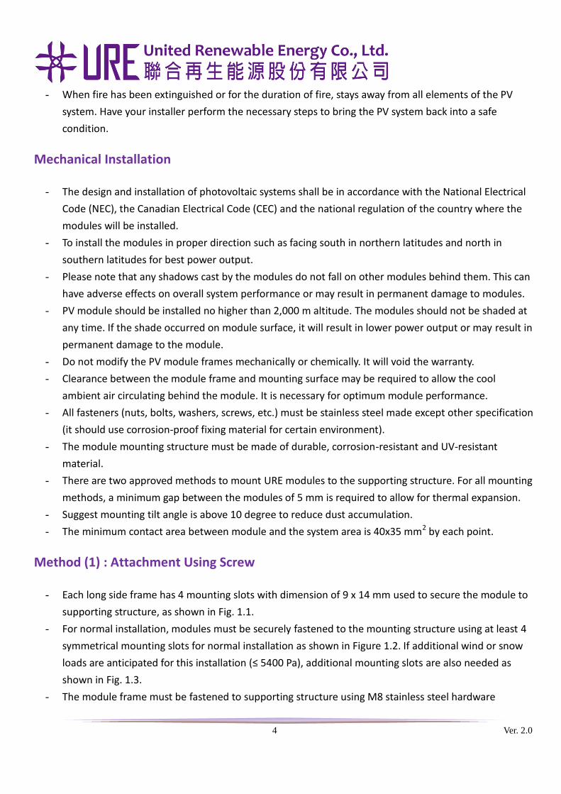
- Each long side frame has 4 mounting slots with dimension of 9 x 14 mm used to secure the module to
supporting structure, as shown in Fig. 1.1.
- For normal installation, modules must be securely fastened to the mounting structure using at least 4
symmetrical mounting slots for normal installation as shown in Figure 1.2. If additional wind or snow
loads are anticipated for this installation (≤ 5400 Pa), additional mounting slots are also needed as
shown in Fig. 1.3.
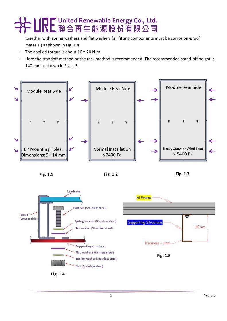
- The module frame must be fastened to supporting structure using M8 stainless steel hardware
5 Ver. 2.0
together with spring washers and flat washers (all fitting components must be corrosion-proof
material) as shown in Fig. 1.4.
- The applied torque is about 16 ~ 20 N-m.
- Here the standoff method or the rack method is recommended. The recommended stand-off height is
140 mm as shown in Fig. 1.5.
Fig. 1.4
Fig. 1.5
Fig. 1.1 Fig. 1.2 Fig. 1.3
6 Ver. 2.0
Method (2) : Attachment Using Clamp
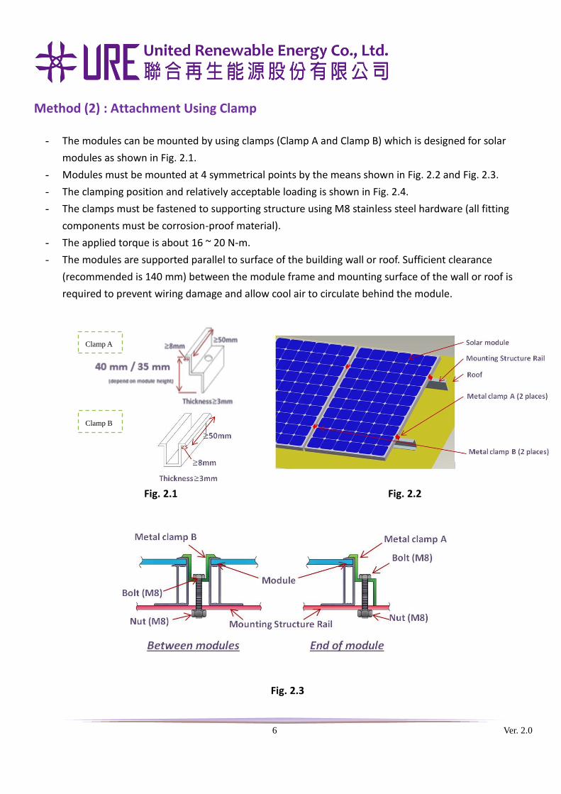
- The modules can be mounted by using clamps (Clamp A and Clamp B) which is designed for solar
modules as shown in Fig. 2.1.
- Modules must be mounted at 4 symmetrical points by the means shown in Fig. 2.2 and Fig. 2.3.
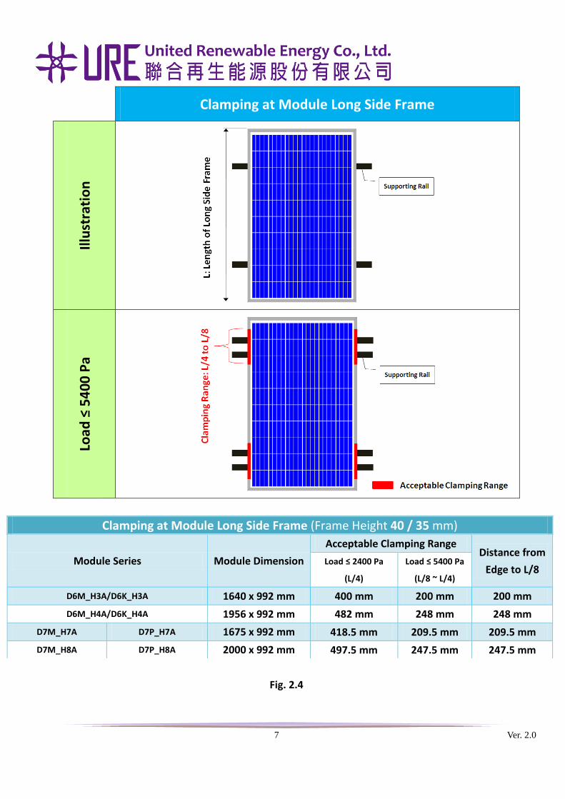
- The clamping position and relatively acceptable loading is shown in Fig. 2.4.
- The clamps must be fastened to supporting structure using M8 stainless steel hardware (all fitting
components must be corrosion-proof material).
- The applied torque is about 16 ~ 20 N-m.
- The modules are supported parallel to surface of the building wall or roof. Sufficient clearance
(recommended is 140 mm) between the module frame and mounting surface of the wall or roof is
required to prevent wiring damage and allow cool air to circulate behind the module.
Fig. 2.2 Fig. 2.1
Fig. 2.3
Clamp A
Clamp B
7 Ver. 2.0
Clamping at Module Long Side Frame
Illu
stra
tio
n
Load
≤ 5
40
0 P
a
Fig. 2.4
Clamping at Module Long Side Frame (Frame Height 40 / 35 mm)
Module Series Module Dimension
Acceptable Clamping Range Distance from
Edge to L/8 Load ≤ 2400 Pa
(L/4)
Load ≤ 5400 Pa
(L/8 ~ L/4)
D6M_H3A/D6K_H3A 1640 x 992 mm 400 mm 200 mm 200 mm
D6M_H4A/D6K_H4A 1956 x 992 mm 482 mm 248 mm 248 mm
D7M_H7A D7P_H7A 1675 x 992 mm 418.5 mm 209.5 mm 209.5 mm
D7M_H8A D7P_H8A 2000 x 992 mm 497.5 mm 247.5 mm 247.5 mm
8 Ver. 2.0
Electrical Installation
Grounding
- All module frames and mounting racks must be properly electrically grounded in accordance with
respective national electrical code and local authority.
- A bolt, screw, or other parts used for bonding purposes within a module or panel shall not be intended
for securing the complete device to the supporting surface or frame.
- Electrically ground the frame of the module or array to avoid the hazards of electric shock and fire.
- Bonding shall be by a positive means, such as clamping, riveting, bolted or screwed connectors,
welding, soldering or brazing. If the bonding means depends upon screw threads, two or more screws,
or two full threads of a single screw must engage the metal.
- The array frame shall be grounded in accordance with NEC requirements for grounding solar electrical
system.
- The module frame must be properly electrically grounded.
- The grounding wire must be properly fastened to the module frame to assure good electrical contacts.
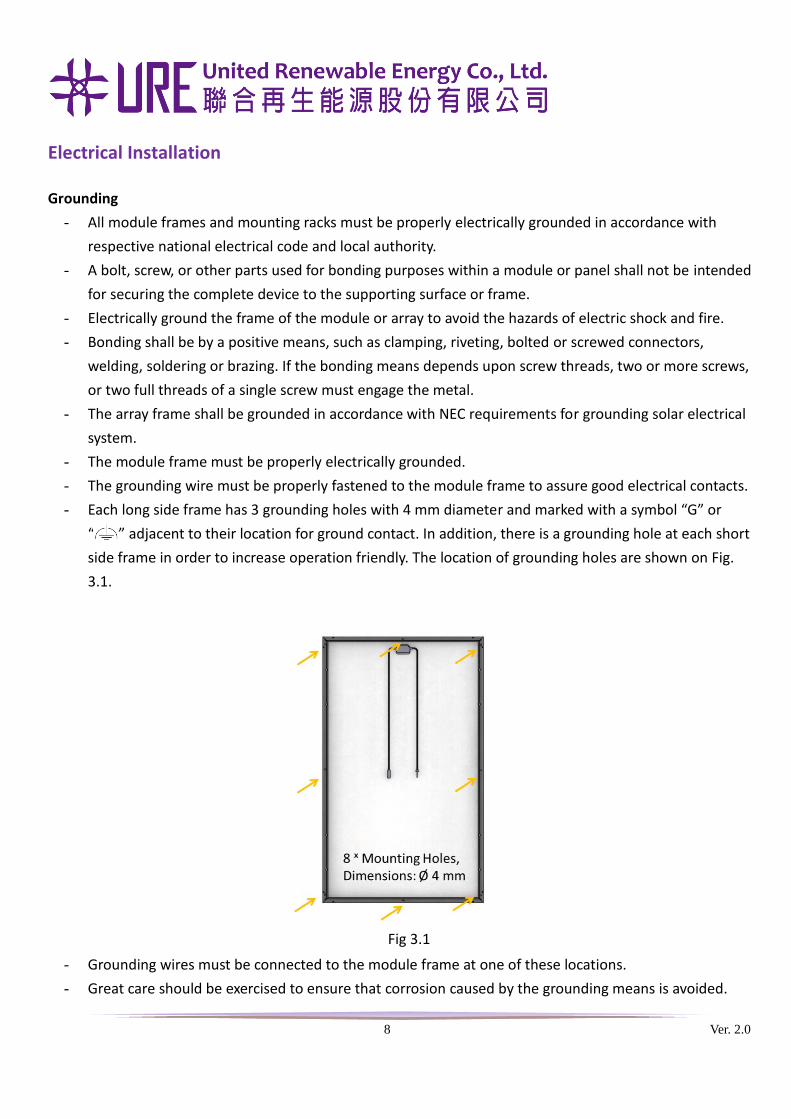
- Each long side frame has 3 grounding holes with 4 mm diameter and marked with a symbol “G” or
“ ” adjacent to their location for ground contact. In addition, there is a grounding hole at each short
side frame in order to increase operation friendly. The location of grounding holes are shown on Fig.
3.1.
- Grounding wires must be connected to the module frame at one of these locations.
- Great care should be exercised to ensure that corrosion caused by the grounding means is avoided.
Fig 3.1
9 Ver. 2.0
- Corrosion can increase the resistance of the grounding connection on the module, or can even cause
the grounding connection to fail entirely.
- Corrosion can be caused by the effects of weather, humidity, dirt and so on. Corrosion can also be
caused when two dissimilar metals contact each other (galvanic action).
- All grounding hardware (nuts, bolts, washers, screws, etc.) must be stainless steel except other
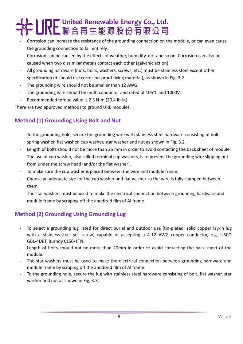
specification (it should use corrosion-proof fixing material), as shown in Fig. 3.2.
- The grounding wire should not be smaller than 12 AWG.
- The grounding wire should be multi conductor and rated of 105°C and 1000V.
- Recommended torque value is 2.3 N-m (20.4 lb-in).
There are two approved methods to ground URE modules.
Method (1) Grounding Using Bolt and Nut
- To the grounding hole, secure the grounding wire with stainless steel hardware consisting of bolt,
spring washer, flat washer, cup washer, star washer and nut as shown in Fig. 3.2.
- Length of bolts should not be more than 25 mm in order to avoid contacting the back sheet of module.
- The use of cup washer, also called terminal cup washers, is to prevent the grounding wire slipping out
from under the screw head (and/or the flat washer).
- To make sure the cup washer is placed between the wire and module frame.
- Choose an adequate size for the cup washer and flat washer so the wire is fully clamped between
them.
- The star washers must be used to make the electrical connection between grounding hardware and
module frame by scraping off the anodized film of Al frame.
Method (2) Grounding Using Grounding Lug
- To select a grounding lug listed for direct burial and outdoor use (tin-plated, solid copper lay-in lug
with a stainless-steel set screw) capable of accepting a 4-12 AWG copper conductor, e.g. ILSCO
GBL-4DBT, Burndy CL50-1TN.
- Length of bolts should not be more than 20mm in order to avoid contacting the back sheet of the
module.
- The star washers must be used to make the electrical connection between grounding hardware and
module frame by scraping off the anodized film of Al frame.
- To the grounding hole, secure the lug with stainless steel hardware consisting of bolt, flat washer, star
washer and nut as shown in Fig. 3.3.
10 Ver. 2.0
Series and Parallel Wiring
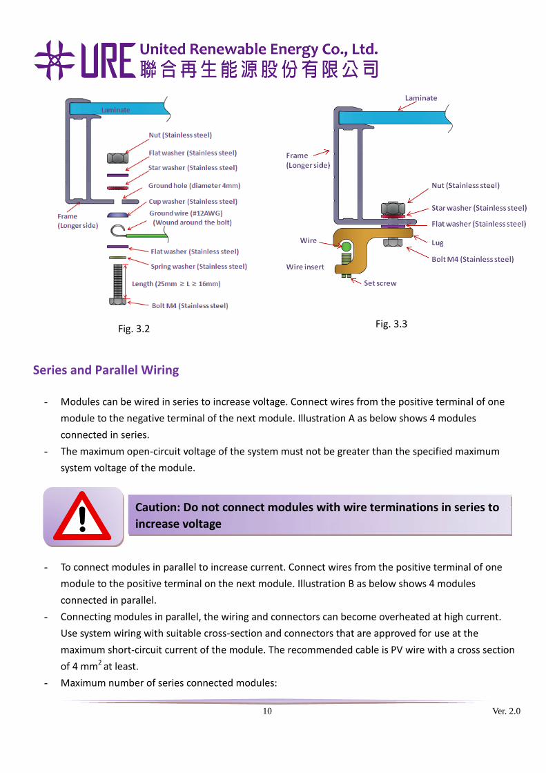
- Modules can be wired in series to increase voltage. Connect wires from the positive terminal of one
module to the negative terminal of the next module. Illustration A as below shows 4 modules
connected in series.
- The maximum open-circuit voltage of the system must not be greater than the specified maximum
system voltage of the module.
- To connect modules in parallel to increase current. Connect wires from the positive terminal of one
module to the positive terminal on the next module. Illustration B as below shows 4 modules
connected in parallel.
- Connecting modules in parallel, the wiring and connectors can become overheated at high current.
Use system wiring with suitable cross-section and connectors that are approved for use at the
maximum short-circuit current of the module. The recommended cable is PV wire with a cross section
of 4 mm2 at least.
- Maximum number of series connected modules:
Fig. 3.2
Caution: Do not connect modules with wire terminations in series to
increase voltage
Fig. 3.3
11 Ver. 2.0
≤ (Maximum system voltage)/(Voc of the module at STC)
- If fuse is used, number of parallel connected modules:
≤ (Maximum fuse rating)/(Isc of the module at STC)
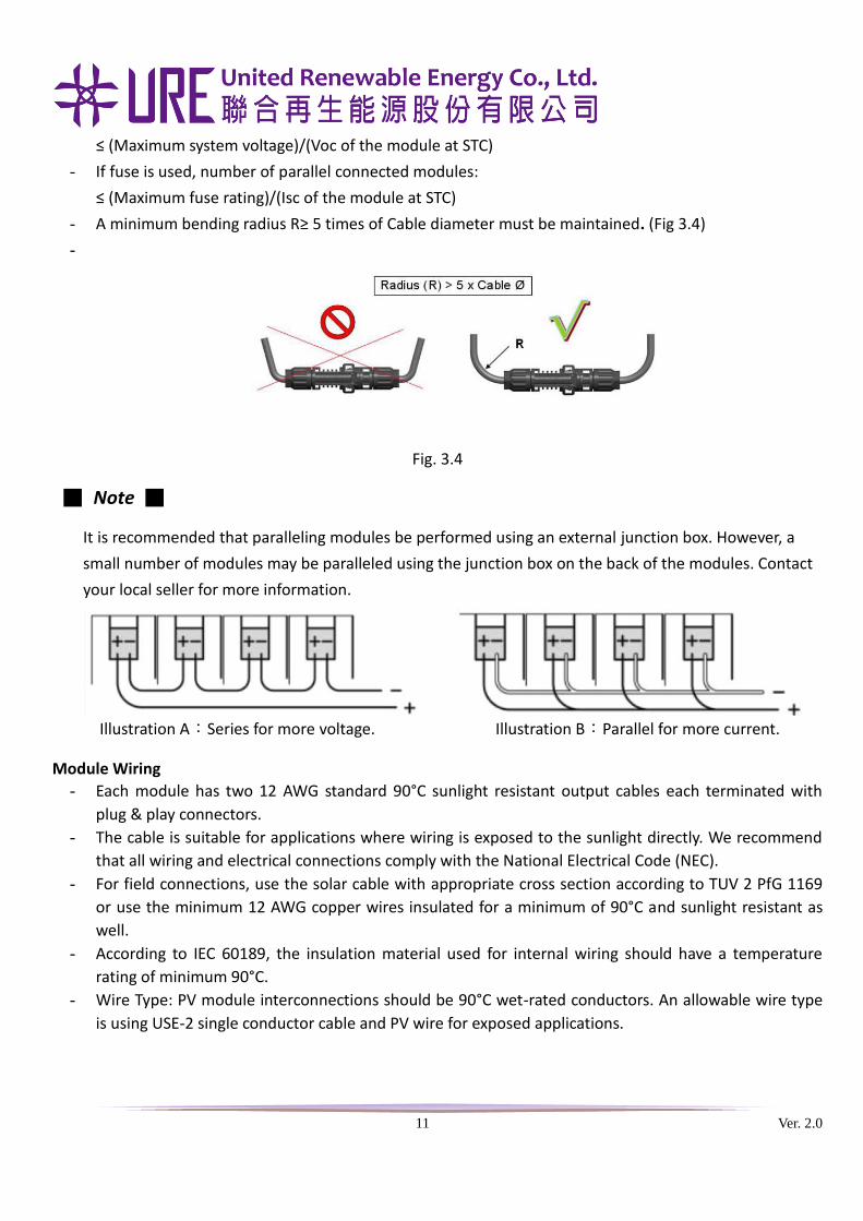
- A minimum bending radius R≥ 5 times of Cable diameter must be maintained. (Fig 3.4)
-
Fig. 3.4
■ Note ■
It is recommended that paralleling modules be performed using an external junction box. However, a
small number of modules may be paralleled using the junction box on the back of the modules. Contact
your local seller for more information.
Module Wiring
- Each module has two 12 AWG standard 90°C sunlight resistant output cables each terminated with
plug & play connectors.
- The cable is suitable for applications where wiring is exposed to the sunlight directly. We recommend
that all wiring and electrical connections comply with the National Electrical Code (NEC).
- For field connections, use the solar cable with appropriate cross section according to TUV 2 PfG 1169
or use the minimum 12 AWG copper wires insulated for a minimum of 90°C and sunlight resistant as
well.
- According to IEC 60189, the insulation material used for internal wiring should have a temperature
rating of minimum 90°C.
- Wire Type: PV module interconnections should be 90°C wet-rated conductors. An allowable wire type
is using USE-2 single conductor cable and PV wire for exposed applications.
Illustration A:Series for more voltage. Illustration B:Parallel for more current.
12 Ver. 2.0
Commissioning & Maintenance All work in commissioning and maintenance of a system must be performed by a qualified PV technician.
Bypass Diode
- Modules have bypass diodes integrated in the junction box and are wired in parallel with series string.
In the unlikely event of diode failure, it is recommended to contact with URE or local agent for
checking / replacing bypass diodes.
- Be cautious of electricity shocks while commissioning and maintaining the solar power system.
Testing
- Test all electrical and electronic components of the system before commissioning.
Maintenance
- Clean the module glass when it’s dirty, use soft water and a soft sponge or cloth for cleaning. A mild,
non-abrasive cleaning agent can be used to remove sticky dirt.
- Check the electrical and mechanical connections regularly to verify they are clean, secure and
undamaged.
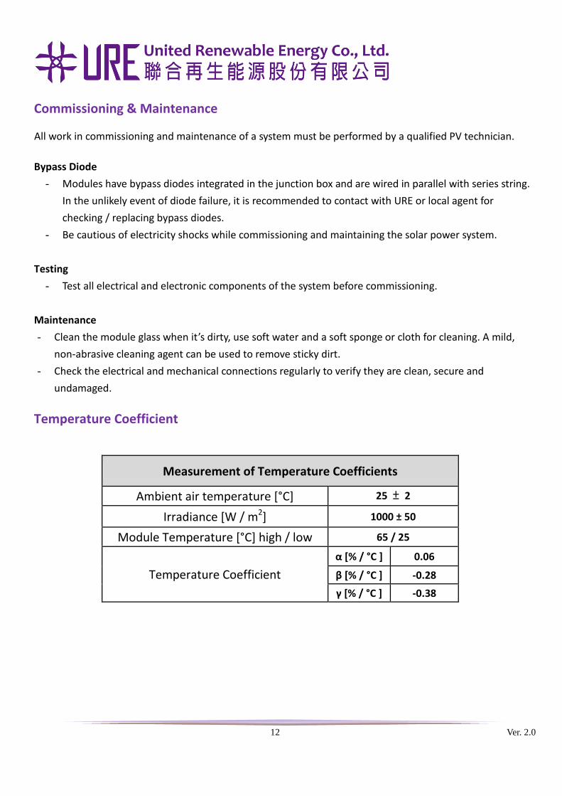
Temperature Coefficient
Measurement of Temperature Coefficients
Ambient air temperature [°C] 25 ± 2
Irradiance [W / m2] 1000 ± 50
Module Temperature [°C] high / low 65 / 25
Temperature Coefficient
α [% / °C ] 0.06
β [% / °C ] -0.28
γ [% / °C ] -0.38
13 Ver. 2.0
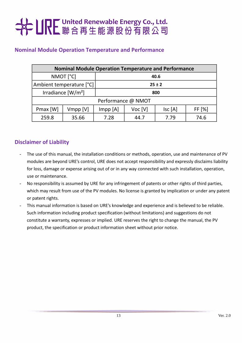
Nominal Module Operation Temperature and Performance
Nominal Module Operation Temperature and Performance
NMOT [°C] 40.6
Ambient temperature [°C] 25 ± 2
Irradiance [W/m²] 800
Performance @ NMOT
Pmax [W] Vmpp [V] Impp [A] Voc [V] Isc [A] FF [%]
259.8 35.66 7.28 44.7 7.79 74.6
Disclaimer of Liability
- The use of this manual, the installation conditions or methods, operation, use and maintenance of PV
modules are beyond URE’s control, URE does not accept responsibility and expressly disclaims liability
for loss, damage or expense arising out of or in any way connected with such installation, operation,
use or maintenance.
- No responsibility is assumed by URE for any infringement of patents or other rights of third parties,
which may result from use of the PV modules. No license is granted by implication or under any patent
or patent rights.
- This manual information is based on URE’s knowledge and experience and is believed to be reliable.
Such information including product specification (without limitations) and suggestions do not
constitute a warranty, expresses or implied. URE reserves the right to change the manual, the PV
product, the specification or product information sheet without prior notice.