Embed Size (px)
Citation preview
Installation Manual
Providing equipment and services to manage controlled-temperature environments for food and other temperature-sensitive products, our Climate Control Technologies sector encompasses both transport and stationary refrigeration solutions. Our product brands include Thermo King®, a world leader in transport temperature control systems, and Hussmann®, a manufacturer of refrigeration and food merchandising equipment.
www.thermoking.com www.hussmann.com www.ingersollrand.com
©2008 Ingersoll-Rand Company Printed in U.S.A. on Recycled Paper
TriPac Diesel Particulate Filter (DPF)Factory and Aftermarket - APU Rear Mounted DPF Installations
Factory and Aftermarket - APU Remote Mounted DPF Installations
TK 53766-19-IM (Rev. 6, 01/12)
Installation Manual
TriPac Diesel Particulate Filter (DPF)
Factory and Aftermarket - APU Rear Mounted DPF Installations
Factory and Aftermarket - APU Remote Mounted DPF Installations
TK 53766-19-IM (Rev. 6, 01/12)
Copyright© 2008 Thermo King Corp., Minneapolis, MN, U.S.A.
Printed in U.S.A.
2
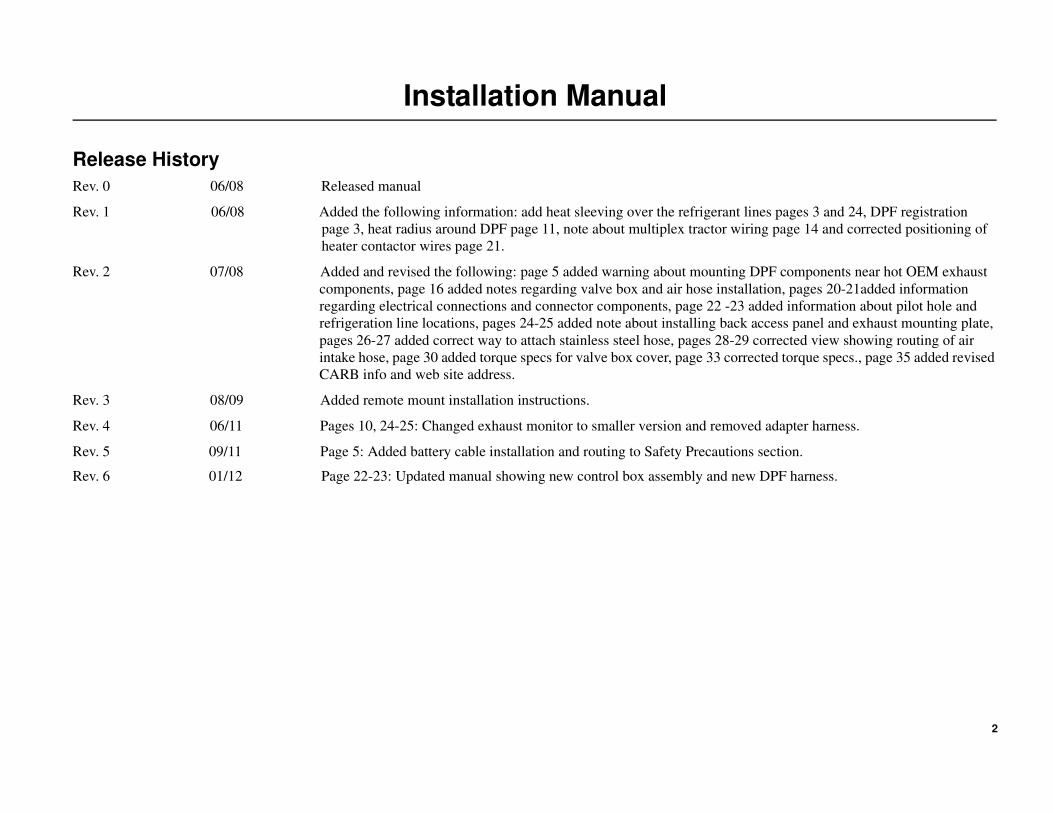
Installation Manual
Release History
Rev. 0 06/08 Released manual
Rev. 1 06/08 Added the following information: add heat sleeving over the refrigerant lines pages 3 and 24, DPF registration
page 3, heat radius around DPF page 11, note about multiplex tractor wiring page 14 and corrected positioning of
heater contactor wires page 21.
Rev. 2 07/08 Added and revised the following: page 5 added warning about mounting DPF components near hot OEM exhaust
components, page 16 added notes regarding valve box and air hose installation, pages 20-21added information
regarding electrical connections and connector components, page 22 -23 added information about pilot hole and
refrigeration line locations, pages 24-25 added note about installing back access panel and exhaust mounting plate,
pages 26-27 added correct way to attach stainless steel hose, pages 28-29 corrected view showing routing of air
intake hose, page 30 added torque specs for valve box cover, page 33 corrected torque specs., page 35 added revised
CARB info and web site address.
Rev. 3 08/09 Added remote mount installation instructions.
Rev. 4 06/11 Pages 10, 24-25: Changed exhaust monitor to smaller version and removed adapter harness.
Rev. 5 09/11 Page 5: Added battery cable installation and routing to Safety Precautions section.
Rev. 6 01/12 Page 22-23: Updated manual showing new control box assembly and new DPF harness.
3
Introduction
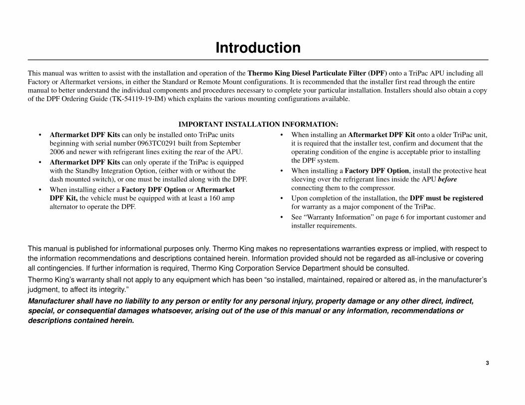
This manual was written to assist with the installation and operation of the Thermo King Diesel Particulate Filter (DPF) onto a TriPac APU including all
Factory or Aftermarket versions, in either the Standard or Remote Mount configurations. It is recommended that the installer first read through the entire
manual to better understand the individual components and procedures necessary to complete your particular installation. Installers should also obtain a copy
of the DPF Ordering Guide (TK-54119-19-IM) which explains the various mounting configurations available.
IMPORTANT INSTALLATION INFORMATION:
• Aftermarket DPF Kits can only be installed onto TriPac units
beginning with serial number 0963TC0291 built from September
2006 and newer with refrigerant lines exiting the rear of the APU.
• Aftermarket DPF Kits can only operate if the TriPac is equipped
with the Standby Integration Option, (either with or without the
dash mounted switch), or one must be installed along with the DPF.
• When installing either a Factory DPF Option or Aftermarket
DPF Kit, the vehicle must be equipped with at least a 160 amp
alternator to operate the DPF.
• When installing an Aftermarket DPF Kit onto a older TriPac unit,
it is required that the installer test, confirm and document that the
operating condition of the engine is acceptable prior to installing
the DPF system.
• When installing a Factory DPF Option, install the protective heat
sleeving over the refrigerant lines inside the APU before
connecting them to the compressor.
• Upon completion of the installation, the DPF must be registered
for warranty as a major component of the TriPac.
• See “Warranty Information” on page 6 for important customer and
installer requirements.
This manual is published for informational purposes only. Thermo King makes no representations warranties express or implied, with respect to
the information recommendations and descriptions contained herein. Information provided should not be regarded as all-inclusive or covering
all contingencies. If further information is required, Thermo King Corporation Service Department should be consulted.
Thermo King’s warranty shall not apply to any equipment which has been “so installed, maintained, repaired or altered as, in the manufacturer’s
judgment, to affect its integrity.”
Manufacturer shall have no liability to any person or entity for any personal injury, property damage or any other direct, indirect,
special, or consequential damages whatsoever, arising out of the use of this manual or any information, recommendations or
descriptions contained herein.
4
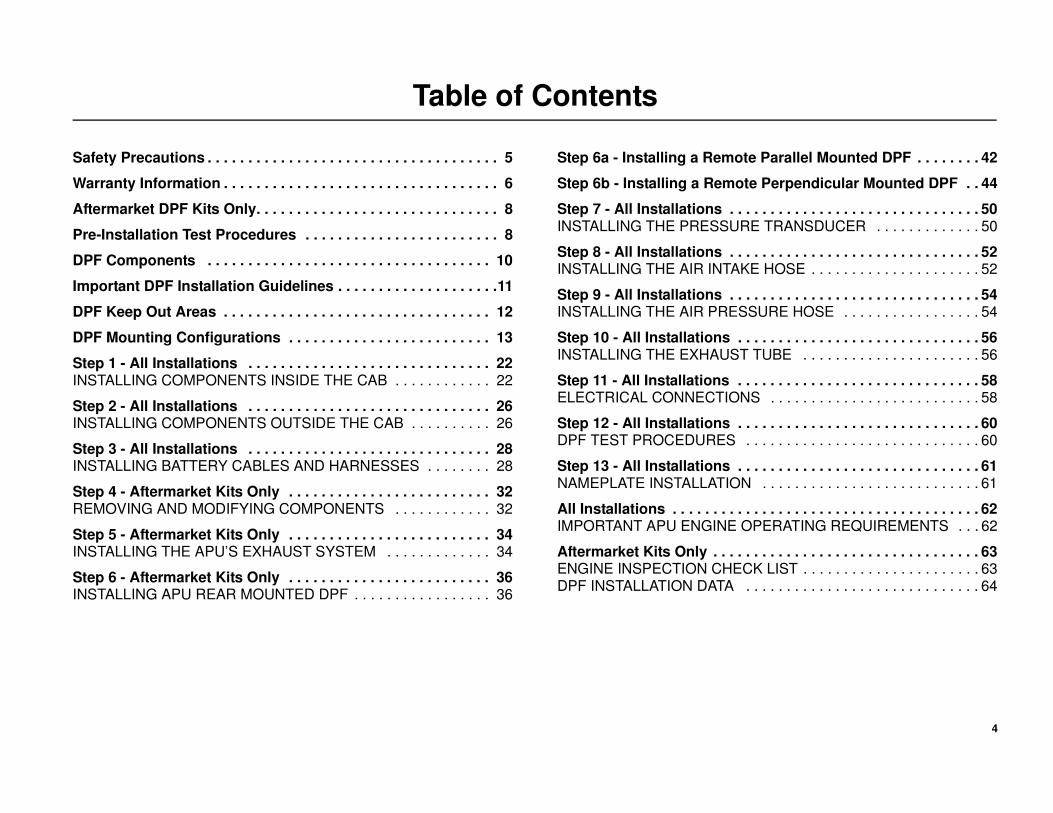
Table of Contents
Safety Precautions . . . . . . . . . . . . . . . . . . . . . . . . . . . . . . . . . . . . 5
Warranty Information . . . . . . . . . . . . . . . . . . . . . . . . . . . . . . . . . . 6
Aftermarket DPF Kits Only. . . . . . . . . . . . . . . . . . . . . . . . . . . . . . 8
Pre-Installation Test Procedures . . . . . . . . . . . . . . . . . . . . . . . . 8
DPF Components . . . . . . . . . . . . . . . . . . . . . . . . . . . . . . . . . . . 10
Important DPF Installation Guidelines . . . . . . . . . . . . . . . . . . . .11
DPF Keep Out Areas . . . . . . . . . . . . . . . . . . . . . . . . . . . . . . . . . 12
DPF Mounting Configurations . . . . . . . . . . . . . . . . . . . . . . . . . 13
Step 1 - All Installations . . . . . . . . . . . . . . . . . . . . . . . . . . . . . . 22INSTALLING COMPONENTS INSIDE THE CAB . . . . . . . . . . . . 22
Step 2 - All Installations . . . . . . . . . . . . . . . . . . . . . . . . . . . . . . 26INSTALLING COMPONENTS OUTSIDE THE CAB . . . . . . . . . . 26
Step 3 - All Installations . . . . . . . . . . . . . . . . . . . . . . . . . . . . . . 28INSTALLING BATTERY CABLES AND HARNESSES . . . . . . . . 28
Step 4 - Aftermarket Kits Only . . . . . . . . . . . . . . . . . . . . . . . . . 32REMOVING AND MODIFYING COMPONENTS . . . . . . . . . . . . 32
Step 5 - Aftermarket Kits Only . . . . . . . . . . . . . . . . . . . . . . . . . 34INSTALLING THE APU’S EXHAUST SYSTEM . . . . . . . . . . . . . 34
Step 6 - Aftermarket Kits Only . . . . . . . . . . . . . . . . . . . . . . . . . 36INSTALLING APU REAR MOUNTED DPF . . . . . . . . . . . . . . . . . 36
Step 6a - Installing a Remote Parallel Mounted DPF . . . . . . . . 42
Step 6b - Installing a Remote Perpendicular Mounted DPF . . 44
Step 7 - All Installations . . . . . . . . . . . . . . . . . . . . . . . . . . . . . . . 50INSTALLING THE PRESSURE TRANSDUCER . . . . . . . . . . . . . 50
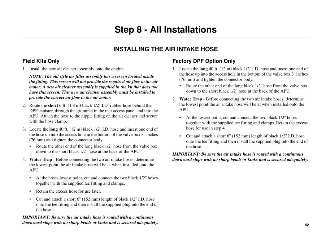
Step 8 - All Installations . . . . . . . . . . . . . . . . . . . . . . . . . . . . . . . 52INSTALLING THE AIR INTAKE HOSE . . . . . . . . . . . . . . . . . . . . . 52
Step 9 - All Installations . . . . . . . . . . . . . . . . . . . . . . . . . . . . . . . 54INSTALLING THE AIR PRESSURE HOSE . . . . . . . . . . . . . . . . . 54
Step 10 - All Installations . . . . . . . . . . . . . . . . . . . . . . . . . . . . . . 56INSTALLING THE EXHAUST TUBE . . . . . . . . . . . . . . . . . . . . . . 56
Step 11 - All Installations . . . . . . . . . . . . . . . . . . . . . . . . . . . . . . 58ELECTRICAL CONNECTIONS . . . . . . . . . . . . . . . . . . . . . . . . . . 58
Step 12 - All Installations . . . . . . . . . . . . . . . . . . . . . . . . . . . . . . 60DPF TEST PROCEDURES . . . . . . . . . . . . . . . . . . . . . . . . . . . . . 60
Step 13 - All Installations . . . . . . . . . . . . . . . . . . . . . . . . . . . . . . 61NAMEPLATE INSTALLATION . . . . . . . . . . . . . . . . . . . . . . . . . . . 61
All Installations . . . . . . . . . . . . . . . . . . . . . . . . . . . . . . . . . . . . . . 62IMPORTANT APU ENGINE OPERATING REQUIREMENTS . . . 62
Aftermarket Kits Only . . . . . . . . . . . . . . . . . . . . . . . . . . . . . . . . . 63ENGINE INSPECTION CHECK LIST . . . . . . . . . . . . . . . . . . . . . . 63DPF INSTALLATION DATA . . . . . . . . . . . . . . . . . . . . . . . . . . . . . 64
5
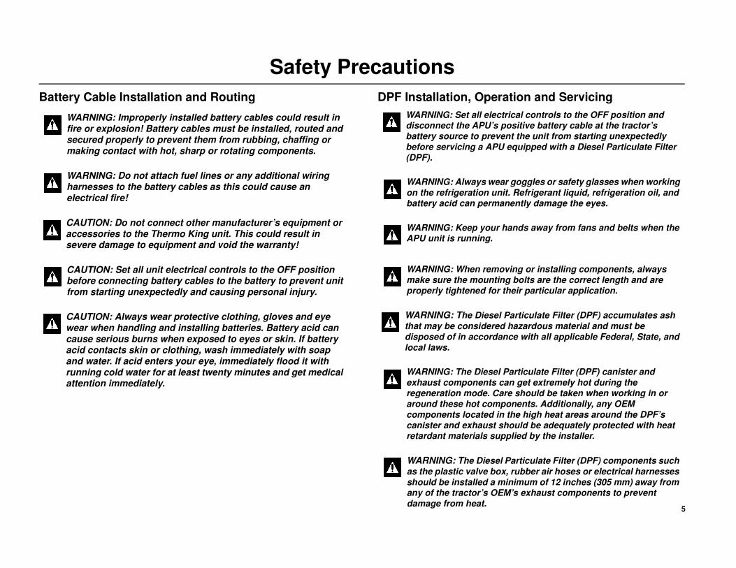
Safety Precautions
Battery Cable Installation and Routing DPF Installation, Operation and Servicing
WARNING: Improperly installed battery cables could result in fire or explosion! Battery cables must be installed, routed and secured properly to prevent them from rubbing, chaffing or making contact with hot, sharp or rotating components.
WARNING: Do not attach fuel lines or any additional wiring harnesses to the battery cables as this could cause an electrical fire!
CAUTION: Do not connect other manufacturer’s equipment or accessories to the Thermo King unit. This could result in severe damage to equipment and void the warranty!
CAUTION: Set all unit electrical controls to the OFF position before connecting battery cables to the battery to prevent unit from starting unexpectedly and causing personal injury.
CAUTION: Always wear protective clothing, gloves and eye wear when handling and installing batteries. Battery acid can cause serious burns when exposed to eyes or skin. If battery acid contacts skin or clothing, wash immediately with soap and water. If acid enters your eye, immediately flood it with running cold water for at least twenty minutes and get medical attention immediately.
WARNING: Set all electrical controls to the OFF position and disconnect the APU’s positive battery cable at the tractor’s battery source to prevent the unit from starting unexpectedly
before servicing a APU equipped with a Diesel Particulate Filter
(DPF).
WARNING: Always wear goggles or safety glasses when working
on the refrigeration unit. Refrigerant liquid, refrigeration oil, and battery acid can permanently damage the eyes.
WARNING: Keep your hands away from fans and belts when the APU unit is running.
WARNING: When removing or installing components, always make sure the mounting bolts are the correct length and are properly tightened for their particular application.
WARNING: The Diesel Particulate Filter (DPF) accumulates ash
that may be considered hazardous material and must be disposed of in accordance with all applicable Federal, State, and local laws.
WARNING: The Diesel Particulate Filter (DPF) canister and exhaust components can get extremely hot during the regeneration mode. Care should be taken when working in or around these hot components. Additionally, any OEM components located in the high heat areas around the DPF’s canister and exhaust should be adequately protected with heat retardant materials supplied by the installer.
WARNING: The Diesel Particulate Filter (DPF) components such
as the plastic valve box, rubber air hoses or electrical harnesses should be installed a minimum of 12 inches (305 mm) away from any of the tractor’s OEM’s exhaust components to prevent
damage from heat.
6
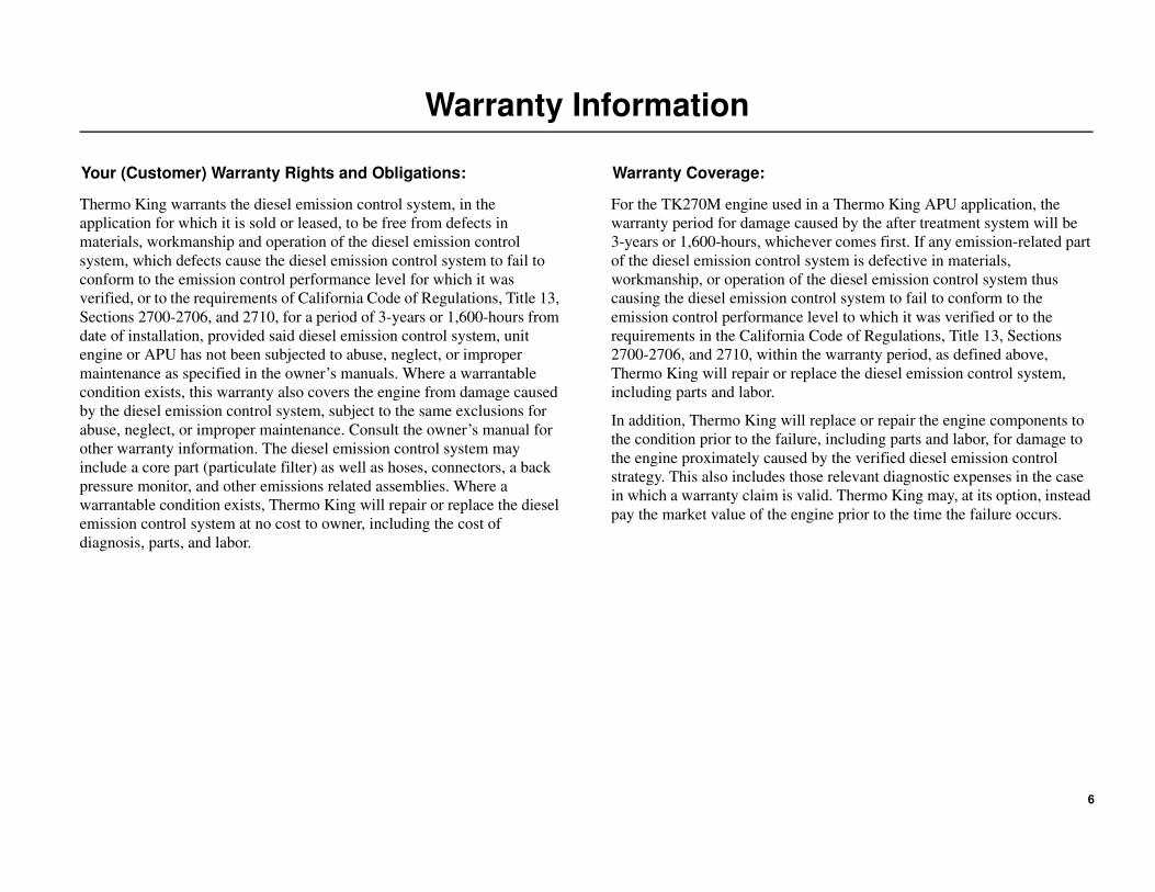
Warranty Information
Your (Customer) Warranty Rights and Obligations:
Thermo King warrants the diesel emission control system, in the
application for which it is sold or leased, to be free from defects in
materials, workmanship and operation of the diesel emission control
system, which defects cause the diesel emission control system to fail to
conform to the emission control performance level for which it was
verified, or to the requirements of California Code of Regulations, Title 13,
Sections 2700-2706, and 2710, for a period of 3-years or 1,600-hours from
date of installation, provided said diesel emission control system, unit
engine or APU has not been subjected to abuse, neglect, or improper
maintenance as specified in the owner’s manuals. Where a warrantable
condition exists, this warranty also covers the engine from damage caused
by the diesel emission control system, subject to the same exclusions for
abuse, neglect, or improper maintenance. Consult the owner’s manual for
other warranty information. The diesel emission control system may
include a core part (particulate filter) as well as hoses, connectors, a back
pressure monitor, and other emissions related assemblies. Where a
warrantable condition exists, Thermo King will repair or replace the diesel
emission control system at no cost to owner, including the cost of
diagnosis, parts, and labor.
Warranty Coverage:
For the TK270M engine used in a Thermo King APU application, the
warranty period for damage caused by the after treatment system will be
3-years or 1,600-hours, whichever comes first. If any emission-related part
of the diesel emission control system is defective in materials,
workmanship, or operation of the diesel emission control system thus
causing the diesel emission control system to fail to conform to the
emission control performance level to which it was verified or to the
requirements in the California Code of Regulations, Title 13, Sections
2700-2706, and 2710, within the warranty period, as defined above,
Thermo King will repair or replace the diesel emission control system,
including parts and labor.
In addition, Thermo King will replace or repair the engine components to
the condition prior to the failure, including parts and labor, for damage to
the engine proximately caused by the verified diesel emission control
strategy. This also includes those relevant diagnostic expenses in the case
in which a warranty claim is valid. Thermo King may, at its option, instead
pay the market value of the engine prior to the time the failure occurs.
7
Warranty Information
Additional Warranty Coverage
In addition to the coverage as stated above, Thermo King will provide a
minimum of 6 months full coverage for installations conducted by
non-certified installers or 12 months of full coverage when an installation
is completed by a certified installer. This applies to DPF’s installed on
existing TriPacs and for DPF’s ordered with new TriPacs.
Owner’s Warranty Responsibility:
Each APU owner is responsible for performing the required maintenance
described in the owner’s manuals. Thermo King recommends that owner
retain all maintenance records and receipts for maintenance expenses for
the APU and diesel emission control system. If such receipts are not kept or
if owner fails to perform all scheduled maintenance, Thermo King may
have grounds to deny warranty coverage. Owner is responsible for
presenting the APU and diesel emission control system to a Thermo King
dealership as soon as a problem is detected. The warranty repair or
replacement should be completed in a reasonable amount of time, not to
exceed 30-days. If a replacement is needed, this may be extended to 90
days should a replacement not be available, but must be performed as soon
as a replacement becomes available.
For questions regarding warranty rights and responsibilities, contact
Thermo King Cold Line by phone at 888-887-2202 or on the web at
http://www.thermoking.com or the California Air Resources Board at 9528
Telstar Avenue, El Monte, California 91731, or 800-363-7664 or electronic
mail: [email protected].
The following is to be furnished to the owner:
Your Warranty Rights and Obligations
(Enter Installer’s Name Here) must warrant that the installation of a diesel
emission control system is free from defects in workmanship or materials
which cause the diesel emission control system to fail to conform to the
emission control performance level it was verified to or to the requirements
in the California Code of Regulations, Title 13, Sections 2700 to 2706. The
warranty period and the extent of the warranty coverage provided by (Enter
Installer’s Name Here) must be the same as the warranty provided by the
product manufacturer, and the same exclusions must apply.
Owner’s Warranty Responsibility
As the APU owner, you are responsible for presenting your APU to (Enter
Installer’s Name Here) as soon as a problem with the installation is
detected.
If you have questions regarding your warranty rights and responsibilities,
you should contact (Enter Installer’s Name and Phone Number Here) or the
California Air Resources Board at 9528 Telstar Avenue, El Monte,
California 91731, or 800-363-7664 or electronic mail:
8
Aftermarket DPF Kits Only
Pre-Installation Test Procedures
IT IS REQUIRED THAT THE INSTALLER TEST, CONFIRM AND DOCUMENT THAT THE OPERATING CONDITION OF THE ENGINE IS
ACCEPTABLE PRIOR TO INSTALLING THE DPF SYSTEM
IMPORTANT: Aftermarket DPF Kits can only be installed onto TriPac
units beginning with serial number 0963TC0291 built from September
2006 and newer with refrigerant lines exiting the rear of the APU.
To assure the DPF emission control system performs as intended, the
Thermo King dealer / certified installer must confirm that the operating
condition of the diesel engine is acceptable before proceeding with the
installation of the DPF system. An engine with excessive oil consumption,
worn valve stem seals or poor injector performance, will cause the DPF
emission control system to become plugged prematurely resulting in high
exhaust back pressure, increased fuel consumption and poor unit
performance. An engine exhibiting these characteristics is considered
unacceptable and the DPF system should not be installed.
An engine is considered acceptable for installation of the DPF system
when the crankcase pressure has been tested and found to be within
specifications, oil consumption is known to be less than approximately 1.1
quarts (1.0 liters) per 200 hours, or 0.28 quarts (0.25 liters) per 50 hours,
and injector service has been performed within the past 3000 hours of
operation. It is the Thermo King dealer / certified installer’s responsibility
to perform tests on the engine, review the APU’s service records and make
any engine repairs as necessary to deem the engine acceptable before
proceeding with the installation of the DPF system.
If the engine is found acceptable, the engine’s operating condition must be
recorded on the Engine Inspection Check List and retained by the Thermo
King dealer / certified installer for a minimum of 3-years (warranty
period).
Quick Preliminary Engine Checkout Procedures
NOTE: This procedure is intended to be used as a quick checkout for pre
evaluation of a unit for possible DPF consideration. This procedure must
then be followed by the completion of the pre installation test procedure
which includes a full running 12.5 hour minimum oil consumption test.
1. Perform a crankcase pressure test using a Magnehelic gauge connected
to the low side of the gauge.
2. Crankcase pressure should be negative. If pressure is positive then
do not install the DPF.
3. If crankcase pressure is negative, perform a visual smoke test. If no
grey or blue smoke is present then proceed with the next step. If the
engine is smoking refer to the Engine Diagnosis Procedure (EDP03)
Excessive Exhaust Smoke found in TK 270 Engine Overhaul Manual
(TK-53163-1-OM) to confirm and correct before proceeding with the
DPF installation.
4. Check for oil in the exhaust system. If oil is present refer to the Engine
Diagnosis Procedure (EDP02) High Oil Consumption found in TK
270 Engine Overhaul Manual (TK-53163-1-OM) to confirm and
correct before proceeding with the DPF installation,
9
Aftermarket DPF Kits Only
Pre-installation Test Procedures
Procedures
1. Review the APU’s service records to confirm the injector service has
been performed within the past 3000 engine hours (or at the time of
DFF installation).
2. Check for oil leaks and repair as necessary.
3. Verify the engine oil condition before proceeding with oil consumption
test. The engine oil must not be full of contaminates or diluted with
fuel. Change the oil and filter if necessary prior to start of the oil
consumption test.
4. Adjust the oil level to the full mark on the dipstick.
5. Run the engine until it has reached full operating temperature
(approximately 15 minutes under full load).
6. Shut the engine off and wait for 10 minutes to allow time for the oil to
drain back.
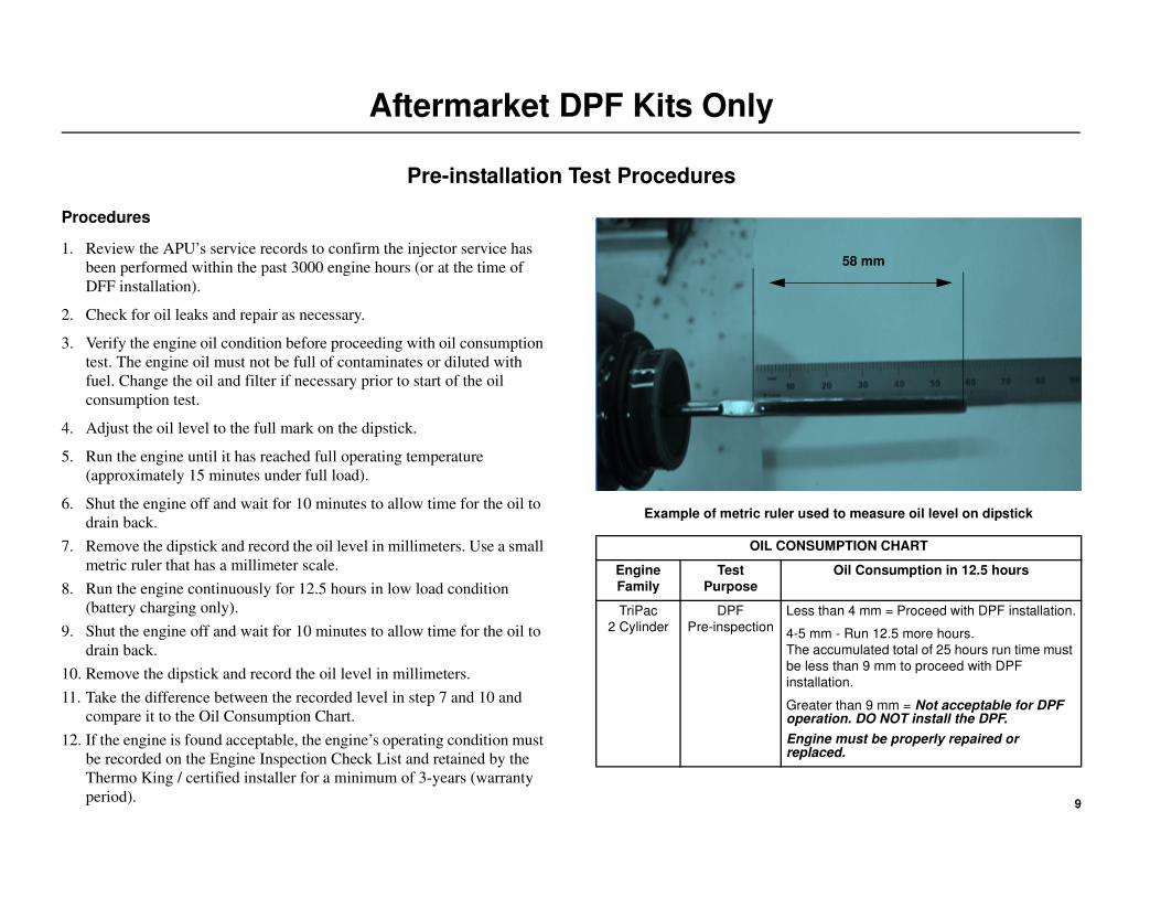
7. Remove the dipstick and record the oil level in millimeters. Use a small
metric ruler that has a millimeter scale.
8. Run the engine continuously for 12.5 hours in low load condition
(battery charging only).
9. Shut the engine off and wait for 10 minutes to allow time for the oil to
drain back.
10. Remove the dipstick and record the oil level in millimeters.
11. Take the difference between the recorded level in step 7 and 10 and
compare it to the Oil Consumption Chart.
12. If the engine is found acceptable, the engine’s operating condition must
be recorded on the Engine Inspection Check List and retained by the
Thermo King / certified installer for a minimum of 3-years (warranty
period).
Example of metric ruler used to measure oil level on dipstick
OIL CONSUMPTION CHART
Engine
Family
Test
Purpose
Oil Consumption in 12.5 hours
TriPac
2 Cylinder
DPF
Pre-inspection
Less than 4 mm = Proceed with DPF installation.
4-5 mm - Run 12.5 more hours.
The accumulated total of 25 hours run time must
be less than 9 mm to proceed with DPF
installation.
Greater than 9 mm = Not acceptable for DPF operation. DO NOT install the DPF.
Engine must be properly repaired or replaced.
58 mm
10
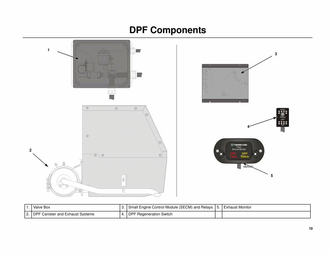
DPF Components
1
2
3
4
5
1. Valve Box 3. Small Engine Control Module (SECM) and Relays 5. Exhaust Monitor
2. DPF Canister and Exhaust Systems 4. DPF Regeneration Switch

11
Important DPF Installation Guidelines
DPF Mounting Locations
The DPF can be mounted two ways, either directly onto the rear of the
APU or remotely from the APU. To help accommodate the numerous OEM
tractor and chassis configurations, various remote mount options are
available which allow the DPF to be mounted either parallel or
perpendicular to the APU, inside or outside the frame rail, or ahead or
down from the APU. Refer to the DPF Ordering Guide (TK-54119) for
more details.
Remote Mount Installations Only
Regardless of the position or location chosen, the DPF must always be
attached to the frame rail in the same manner (claw or direct mount) as the
TriPac APU. This keeps the exhaust system from the APU to the DPF in
proper alignment. Direct mount kits are available to match a direct mount
APU installation.
• If the APU is claw mounted to the tractor’ s frame - the DPF must
be claw mounted to the frame.
• If the APU is direct mounted to the tractor’s frame - the DPF must
be direct mounted to the frame.
• If the APU uses 1.5'' spacer bars - the DPF must use 1.5'' spacer
bars.
• If the APU uses 2.5'' spacer bars - the DPF must use 2.5'' spacer
bars.
Truck Integration Switch
All TriPac’s equipped with a DPF must have a TriPac Integration package
installed.
Safety Details
It is also important that the following safety details are observed when
installing either a rear APU mounted DPF or a remote mounted DPF:
• The installation and location of DPF must not interfere with the
safe operation of the tractor or any of it’s components.
• The DPF assembly must only be installed onto the tractor’s frame
rail using only the supplied (claw or direct mount) hardware, and
torqued to proper specifications.
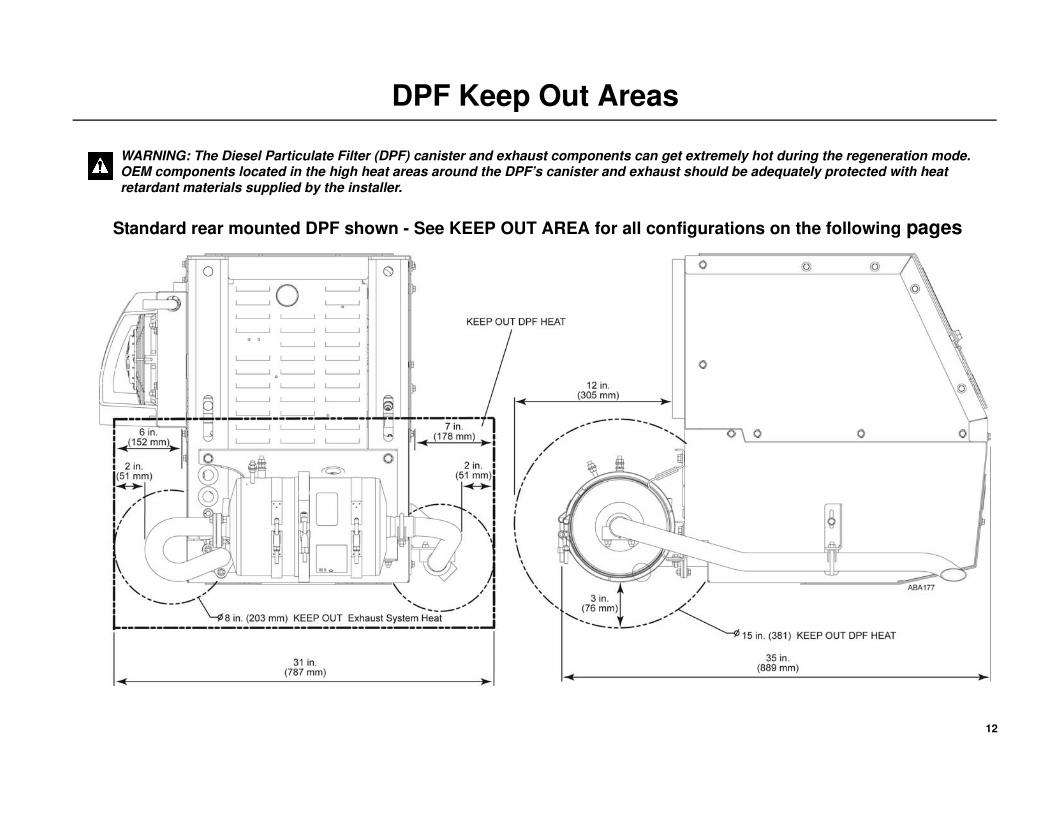
• The DPF KEEP OUT AREA must be observed. This area is
defined as the 15'' circumference around the DPF canister, or 3''
from any part of the canister or exhaust tubes which can get
extremely hot. OEM components in this area may need to be safely
relocated or adequately protected from excessive heat generated by
the DPF.
• The APU’s exhaust system must be properly assembled and
connected to the DPF canister using only the supplied exhaust
system components. NOTE: The use of exhaust components other
then those supplied by Thermo King will void the warranty.
• The correct alignment and torque sequence of the exhaust system
must be followed as specified to prevent exhaust leaks.
• When the APU or DPF is installed behind tractor fairings, skirting,
etc., the exhaust outlet must be routed out to an open area to prevent
exhaust fumes from entering the passenger compartment which
could result in carbon monoxide poising or death by asphyxiation.
• All electrical harnesses and air hoses must be properly installed to
prevent contact with any sharp edges, moving, rotating, or hot
components.
12
DPF Keep Out Areas
Standard rear mounted DPF shown - See KEEP OUT AREA for all configurations on the following pages
WARNING: The Diesel Particulate Filter (DPF) canister and exhaust components can get extremely hot during the regeneration mode. OEM components located in the high heat areas around the DPF’s canister and exhaust should be adequately protected with heat retardant materials supplied by the installer.
13
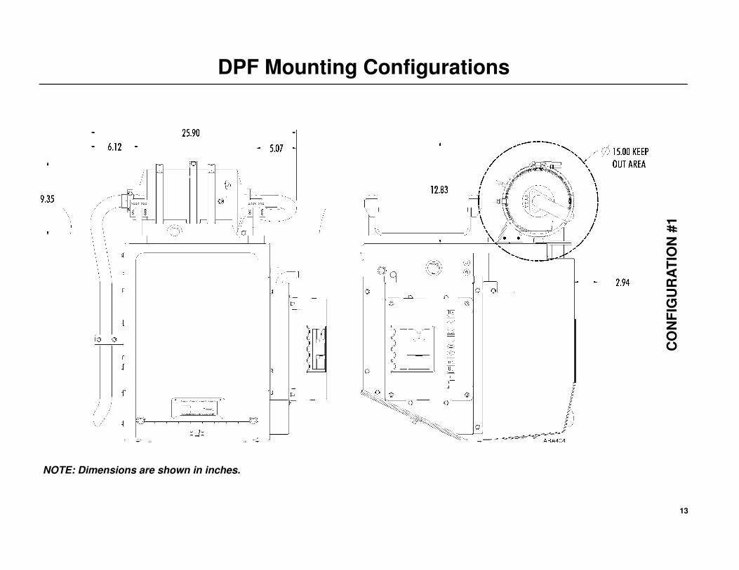
DPF Mounting Configurations
CO
NF
IGU
RA
TIO
N #
1
NOTE: Dimensions are shown in inches.
14
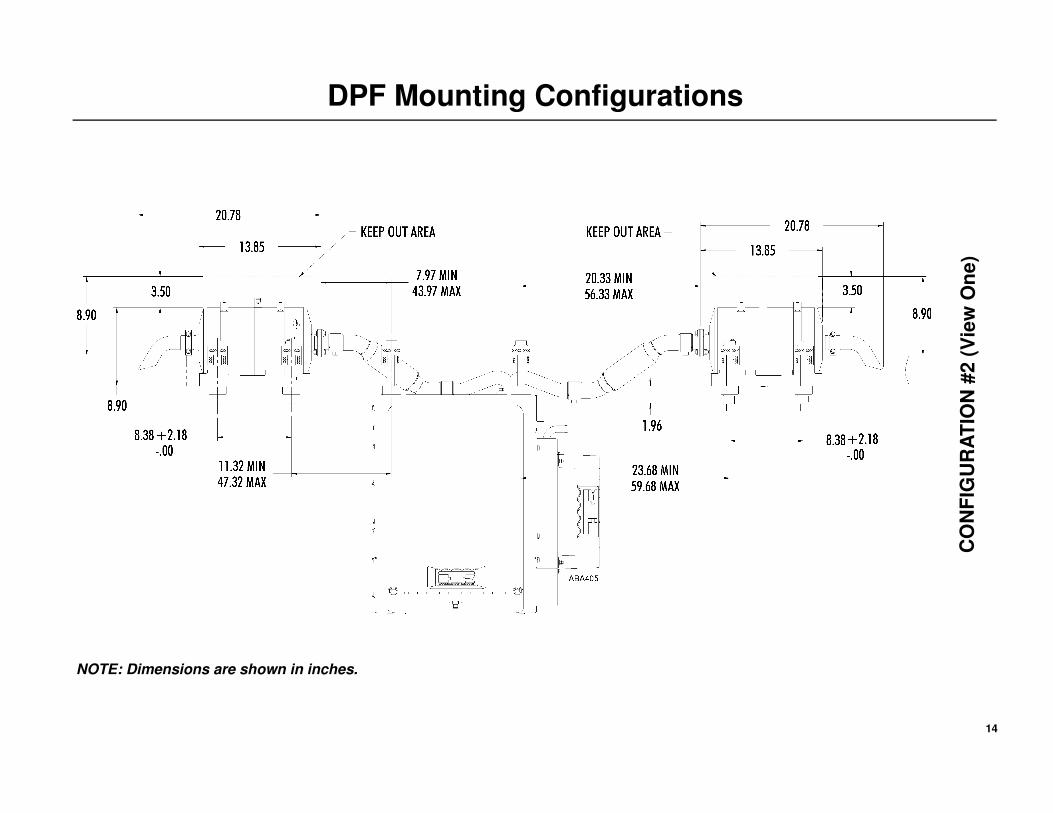
DPF Mounting Configurations
CO
NF
IGU
RA
TIO
N #
2 (
Vi e
w O
ne
)
NOTE: Dimensions are shown in inches.
15
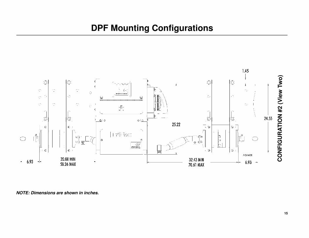
DPF Mounting Configurations
CO
NF
IGU
RA
TIO
N #
2 (
Vi e
w T
wo
)
NOTE: Dimensions are shown in inches.
16
DPF Mounting Configurations
CO
NF
IGU
RA
TIO
N #
3 (
Vie
w O
ne
)
NOTE: Dimensions are shown in inches.
17
DPF Mounting Configurations
CO
NF
IGU
RA
TIO
N #
3 (
Vie
w T
wo
)
NOTE: Dimensions are shown in inches.
18
DPF Mounting Configurations
CO
NF
IGU
RA
TIO
N #
4 (
Vie
w O
ne
)
NOTE: Dimensions are shown in inches.
19
DPF Configurations
CO
NF
IGU
RA
TI O
N #
4 (
Vie
w T
wo
)
NOTE: Dimensions are shown in inches.
20
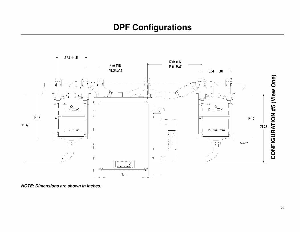
DPF Configurations
CO
NF
IGU
RA
TIO
N #
5 (
Vie
w O
ne
)
NOTE: Dimensions are shown in inches.
21
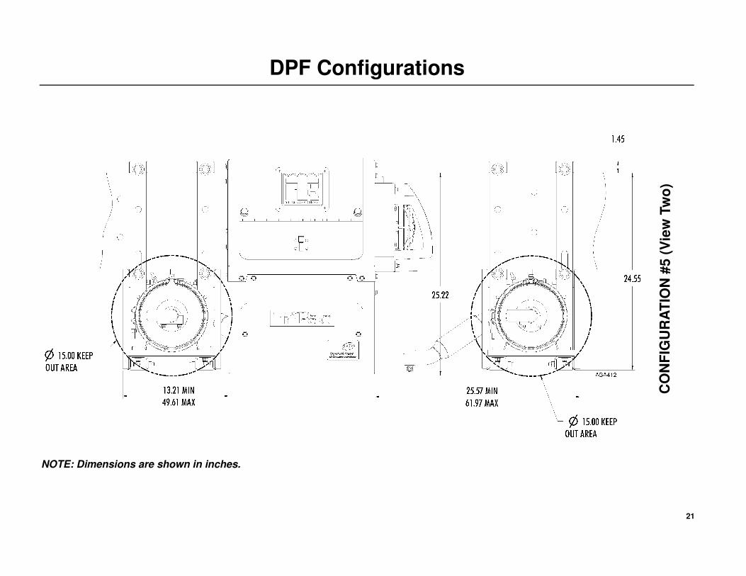
DPF Configurations
CO
NF
IGU
RA
TIO
N #
5 (
Vie
w T
wo
)
NOTE: Dimensions are shown in inches.
22
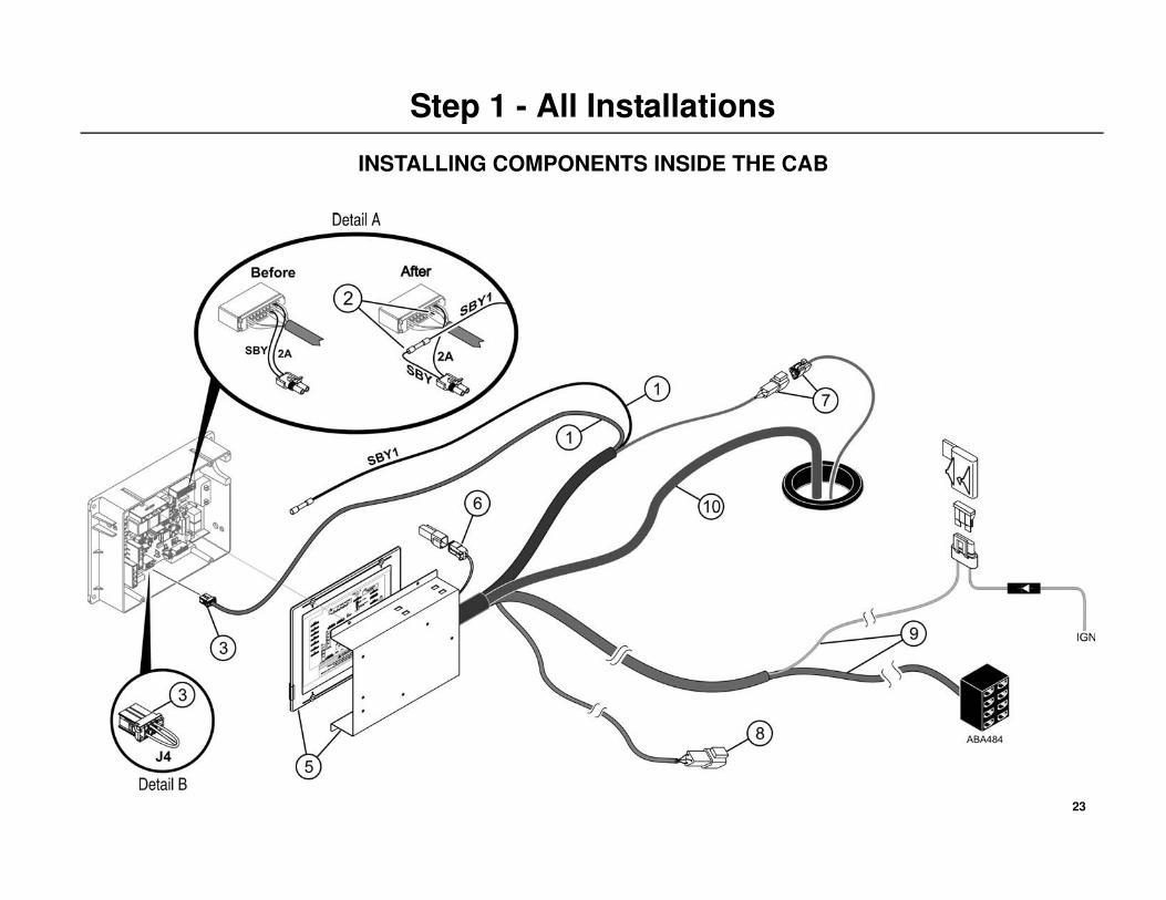
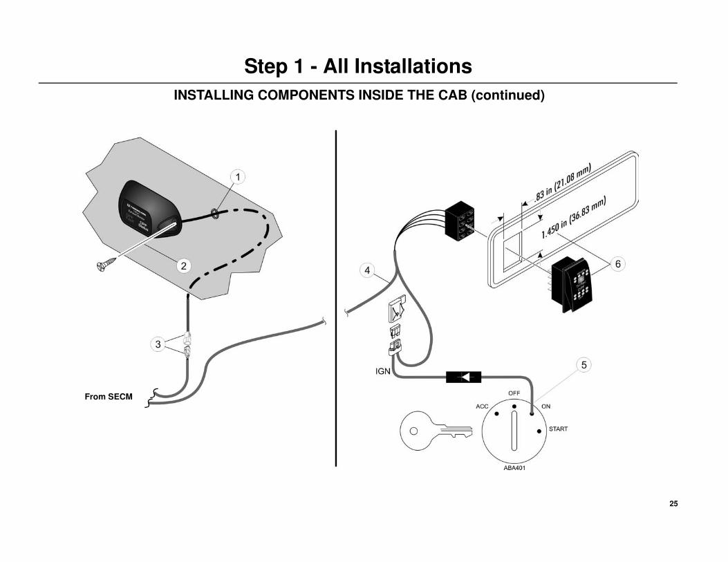
Step 1 - All Installations
INSTALLING COMPONENTS INSIDE THE CAB
Small Engine Control Module (SECM)
IMPORTANT: Superlube(203-524) or equivalent should be applied to all
electrical connections.
Locate the existing TriPac control box inside the cab. Remove the cover
and place the SECM box next to the control box.
1. Route the short harness from the SECM into the TriPac control box.
• The short harness has a single wire with a butt splice connector
(SBY1), along with the DPF 6-pin connector.
2. DETAIL A - Inside the TriPac control box, locate the existing 2-pin
connector (SBY, 2A) coming from the 20-Pin connector (J14) on the
interface board.
• Cut the SBY wire off flush with the 20-pin connector.
DO NOT cut the 2A wire.
• Strip the end of the SBY wire and attach the new SBY1 wire from
the SECM harness using the attached butt splice.
3. DETAIL B - Locate the DPF jump connector (J4) on the interface
board.
• Remove and discard this jump connector.
• Attach the 6-pin connector from the SECM harness to mating (J4)
connector.
4. Neatly secure all harnesses inside the box with tie bands.
5. Place the cover back onto the TriPac control box and position the
SECM assembly on top of the cover. Secure with the four screws.
6. The 2-pin CAN connector (CAN1,CAN2) is used for diagnostic
purposes and can be secured with a tie band to another harness.
7. FIELD KIT ONLY - Drill a 2.00” (50 mm) access hole in the floor.
Cut and install a piece of split loom (or similar) around the inside edge
of the hole to provide protection for the harnesses.
• Attach the separate APU Pressure Transducer harness with the
3-pin connector (EPN, EP1, P) supplied in the installation kit to the
mating 3-pin connector from the SECM harness.
• Route this harness through the access hole in the floor. This harness
will be installed onto the APU in a later step.
8. Route the 3-pin connector (RED, 2B-01, Yel) up towards the sleeper
area. This will be connected to the Exhaust Monitor in a later step.
9. Route the Regeneration Switch and Ignition harnesses up towards the
tractor’s dash. These harnesses will be installed in a later step.
10. Route the remaining SECM harnesses out through the access hole in
the floor. These harnesses will be installed later.
WARNING: Set all electrical controls to the OFF position and
disconnect the APU’s positive battery cable at the tractor’s battery
source to prevent the unit from starting unexpectedly.
23
Step 1 - All Installations
INSTALLING COMPONENTS INSIDE THE CAB
24
Step 1 - All Installations
INSTALLING COMPONENTS INSIDE THE CAB (continued)
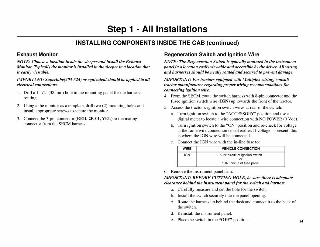
Exhaust Monitor
NOTE: Choose a location inside the sleeper and install the Exhaust
Monitor. Typically the monitor is installed in the sleeper in a location that
is easily viewable.
IMPORTANT: Superlube(203-524) or equivalent should be applied to all
electrical connections.
1. Drill a 1-1/2'' (38 mm) hole in the mounting panel for the harness
routing.
2. Using a the monitor as a template, drill two (2) mounting holes and
install appropriate screws to secure the monitor.
3. Connect the 3-pin connector (RED, 2B-01, YEL) to the mating
connector from the SECM harness.
Regeneration Switch and Ignition Wire
NOTE: The Regeneration Switch is typically mounted in the instrument
panel in a location easily viewable and accessible by the driver. All wiring
and harnesses should be neatly routed and secured to prevent damage.
IMPORTANT: For tractors equipped with Multiplex wiring, consult
tractor manufacturer regarding proper wiring recommendations for
connecting ignition wire.
4. From the SECM, route the switch harness with 8-pin connector and the
fused ignition switch wire (IGN) up towards the front of the tractor.
5. Access the tractor’s ignition switch wires at rear of the switch:
a. Turn ignition switch to the “ACCESSORY” position and use a
digital meter to locate a wire connection with NO POWER (0 Vdc).
b. Turn ignition switch to the “ON” position and re-check for voltage
at the same wire connection tested earlier. If voltage is present, this
is where the IGN wire will be connected.
c. Connect the IGN wire with the in-line fuse to:
6. Remove the instrument panel trim.
IMPORTANT: BEFORE CUTTING HOLE, be sure there is adequate
clearance behind the instrument panel for the switch and harness.
a. Carefully measure and cut the hole for the switch.
b. Install the switch securely into the panel opening.
c. Route the harness up behind the dash and connect it to the back of
the switch.
d. Reinstall the instrument panel.
e. Place the switch in the “OFF” position.
WIRE VEHICLE CONNECTION
IGN “ON” circuit of ignition switch
or
“ON” circuit of fuse panel
25
Step 1 - All Installations
INSTALLING COMPONENTS INSIDE THE CAB (continued)
From SECM
26
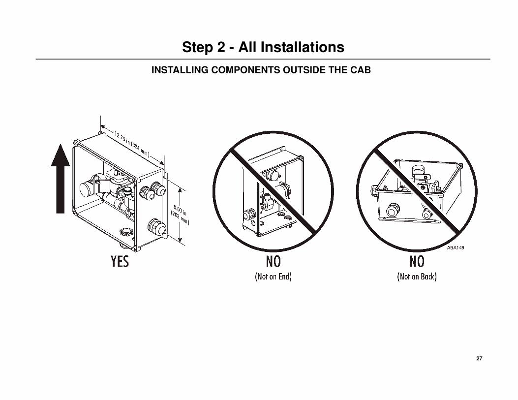
Step 2 - All Installations
INSTALLING COMPONENTS OUTSIDE THE CAB
Valve Box Location
IMPORTANT: The location of the valve box is critical to the proper
operation of the DPF system. The box must be installed in a location that
does not interfere with the safe operation of existing truck components.
The rear exterior of the cab/sleeper is the preferred location. Before
drilling any hole in the tractor, check for interference with internal wires,
supports or interior panels. Avoid drilling into the truck’s interior support
members as this could void the tractor’s OEM warranty.
NOTE: Do not drill holes in the valve box - It must remain airtight.
1. The following installation requirements must be followed:
• The valve box must be mounted higher than the DPF canister.
• The box must be mounted in a location to allow the cover to be
removed for service.
• The valve box must only be mounted upright as shown.
It can not be installed sideways or flat.
• The valve box must be mounted flat and secure to the truck’s
exterior surface, not on top of OEM rivets, bolts, etc. Spacers may
be required and supplied by the installer.
• Use only the existing four mounting holes to mount the box.
• Do not over tighten the mounting bolts or damage to the box will
result.
• Allow sufficient room to route battery cables and air hoses to the
box.
• Air hoses must be routed in a continuous downward slope.
WARNING: The valve box, rubber air hoses and electrical
harnesses should be installed a minimum of 12 inches (305 mm)
away from any of the tractor’s exhaust components to prevent
damage from heat.
27
Step 2 - All Installations
INSTALLING COMPONENTS OUTSIDE THE CAB
28
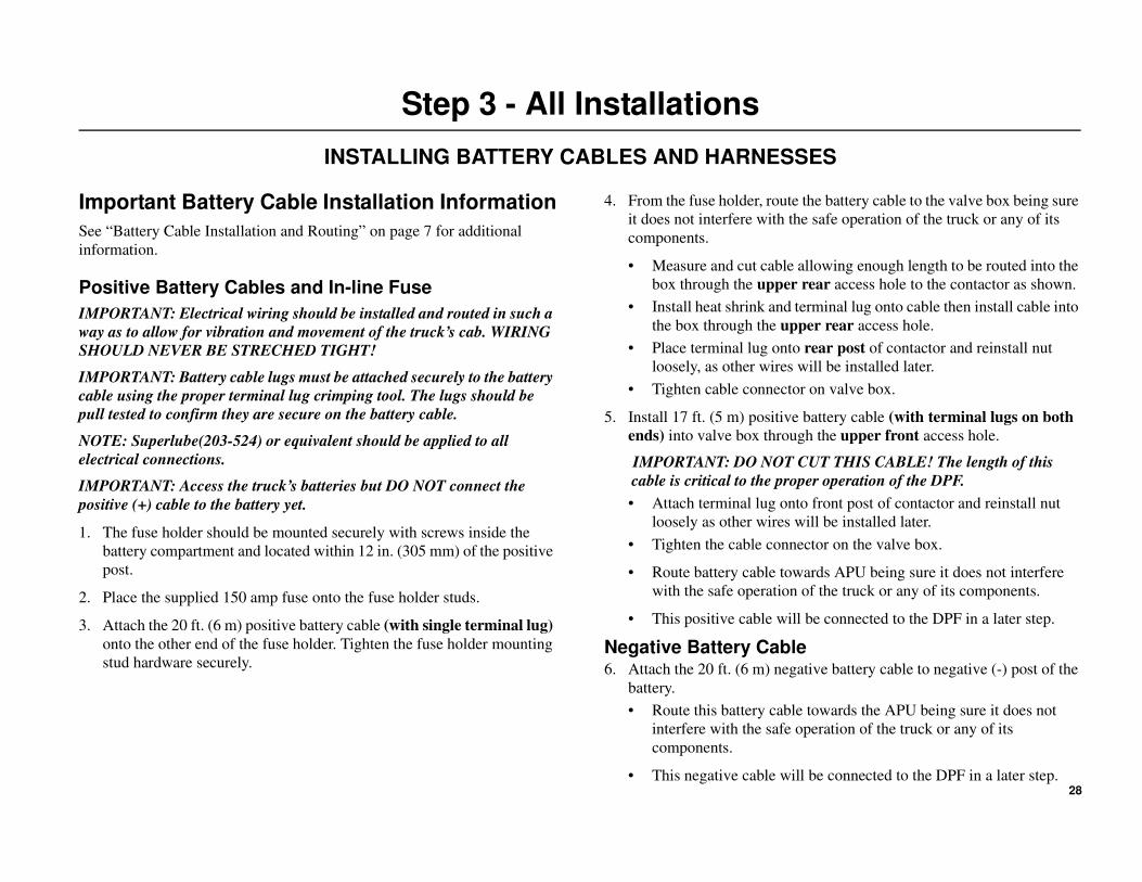
Step 3 - All Installations
INSTALLING BATTERY CABLES AND HARNESSES
Important Battery Cable Installation Information
See “Battery Cable Installation and Routing” on page 7 for additional
information.
Positive Battery Cables and In-line Fuse
IMPORTANT: Electrical wiring should be installed and routed in such a
way as to allow for vibration and movement of the truck’s cab. WIRING
SHOULD NEVER BE STRECHED TIGHT!
IMPORTANT: Battery cable lugs must be attached securely to the battery
cable using the proper terminal lug crimping tool. The lugs should be
pull tested to confirm they are secure on the battery cable.
NOTE: Superlube(203-524) or equivalent should be applied to all
electrical connections.
IMPORTANT: Access the truck’s batteries but DO NOT connect the
positive (+) cable to the battery yet.
1. The fuse holder should be mounted securely with screws inside the
battery compartment and located within 12 in. (305 mm) of the positive
post.
2. Place the supplied 150 amp fuse onto the fuse holder studs.
3. Attach the 20 ft. (6 m) positive battery cable (with single terminal lug)
onto the other end of the fuse holder. Tighten the fuse holder mounting
stud hardware securely.
4. From the fuse holder, route the battery cable to the valve box being sure
it does not interfere with the safe operation of the truck or any of its
components.
• Measure and cut cable allowing enough length to be routed into the
box through the upper rear access hole to the contactor as shown.
• Install heat shrink and terminal lug onto cable then install cable into
the box through the upper rear access hole.
• Place terminal lug onto rear post of contactor and reinstall nut
loosely, as other wires will be installed later.
• Tighten cable connector on valve box.
5. Install 17 ft. (5 m) positive battery cable (with terminal lugs on both
ends) into valve box through the upper front access hole.
IMPORTANT: DO NOT CUT THIS CABLE! The length of this
cable is critical to the proper operation of the DPF.
• Attach terminal lug onto front post of contactor and reinstall nut
loosely as other wires will be installed later.
• Tighten the cable connector on the valve box.
• Route battery cable towards APU being sure it does not interfere
with the safe operation of the truck or any of its components.
• This positive cable will be connected to the DPF in a later step.
Negative Battery Cable6. Attach the 20 ft. (6 m) negative battery cable to negative (-) post of the
battery.
• Route this battery cable towards the APU being sure it does not
interfere with the safe operation of the truck or any of its
components.
• This negative cable will be connected to the DPF in a later step.
29
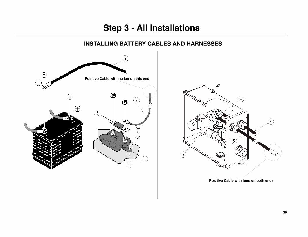
Step 3 - All Installations
Positive Cable with no lug on this end
Positive Cable with lugs on both ends
INSTALLING BATTERY CABLES AND HARNESSES
30
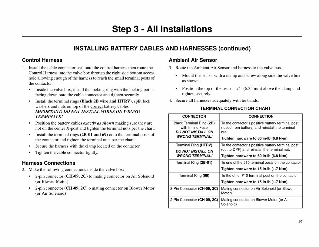
Step 3 - All Installations
INSTALLING BATTERY CABLES AND HARNESSES (continued)
Control Harness
1. Install the cable connector seal onto the control harness then route the
Control Harness into the valve box through the right side bottom access
hole allowing enough of the harness to reach the small terminal posts of
the contactor.
• Inside the valve box, install the locking ring with the locking points
facing down onto the cable connector and tighten securely.
• Install the terminal rings (Black 2B wire and HTRV), split lock
washers and nuts on top of the correct battery cables.
IMPORTANT: DO NOT INSTALL WIRES ON WRONG
TERMINALS!
• Position the battery cables exactly as shown making sure they are
not on the center X-post and tighten the terminal nuts per the chart.
• Install the terminal rings (2B-01 and 69) onto the terminal posts of
the contactor and tighten the terminal nuts per the chart.
• Secure the harness with the clamp located on the contactor.
• Tighten the cable connector tightly.
Harness Connections2. Make the following connections inside the valve box:
• 2-pin connector (CH-09, 2C) to mating connector on Air Solenoid
(or Blower Motor).
• 2-pin connector (CH-09, 2C) o mating connector on Blower Motor
(or Air Solenoid)
Ambient Air Sensor
3. Route the Ambient Air Sensor and harness to the valve box.
• Mount the sensor with a clamp and screw along side the valve box
as shown.
• Position the top of the sensor 1/4'' (6.35 mm) above the clamp and
tighten securely.
4. Secure all harnesses adequately with tie bands.
TERMINAL CONNECTION CHART
CONNECTOR CONNECTION
Black Terminal Ring (2B)
with In-line Fuse
DO NOT INSTALL ON
WRONG TERMINAL!
To the contactor’s positive battery terminal post
(fused from battery) and reinstall the terminal
nut.
Tighten hardware to 60 in-lb (6.8 N•m).
Terminal Ring (HTRV)
DO NOT INSTALL ON
WRONG TERMINAL!
To the contactor’s positive battery terminal post
(out to DPF) and reinstall the terminal nut.
Tighten hardware to 60 in-lb (6.8 N•m).
Terminal Ring (2B-01) To one of the #10 terminal posts on the contactor
Tighten hardware to 15 in-lb (1.7 N•m).
Terminal Ring (69) To the other #10 terminal post on the contactor
Tighten hardware to 15 in-lb (1.7 N•m).
2-Pin Connector (CH-09, 2C) Mating connector on Air Solenoid (or Blower
Motor)
2-Pin Connector (CH-09, 2C) Mating connector on Blower Motor (or Air
Solenoid)
31
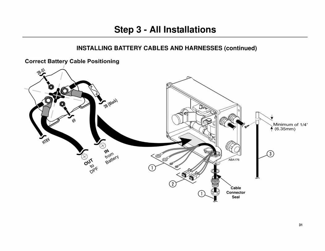
Step 3 - All Installations
Cable
Connector
Seal
INSTALLING BATTERY CABLES AND HARNESSES (continued)
32
Step 4 - Aftermarket Kits Only
REMOVING AND MODIFYING COMPONENTS
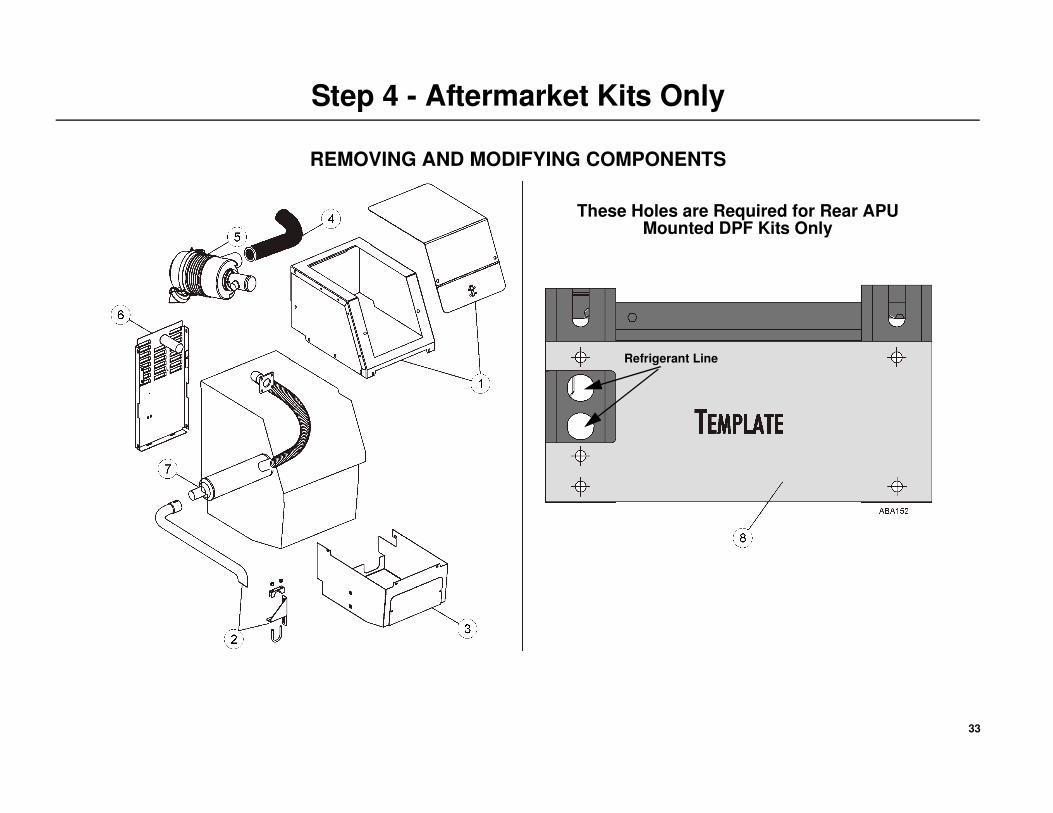
Component Removal
NOTE: The following components must be removed from the APU when
installing any aftermarket DPF kits onto field units.
1. Remove the top enclosure and access cover.
2. Unbolt the clamp securing the tailpipe to the side panel of the APU,
remove and discard the tailpipe.
3. Remove the lower panel and access cover.
4. Disconnect and remove the air cleaner hose from the fresh air intake
tube.
5. Remove and discard the air cleaner assembly from the APU.
6. Remove and discard the muffler straps and rear panel from the APU.
7. Remove and discard the complete APU exhaust system by:
• unbolting and removing the exhaust tube at the manifold
• loosening and removing the muffler
• removing any old gasket material from the exhaust manifold.
APU Frame Modifications
NOTE: These APU frame modifications are required only when
installing a standard rear mounted DPF kit onto older field units that do
not have these holes. Later production units have the holes in the frame
from the factory. Skip this section if your unit has these holes.
8. Clean the rear lower section of the APU frame of any grease or dirt and
position the supplied template onto the frame as shown and center
punch the holes.
• Drill a 1/8'' pilot hole.
• Use a 13/32'' (10 mm) drill to drill the five (5) holes for mounting
the DPF assembly.
• Remove and discard the template.
33
Step 4 - Aftermarket Kits Only
REMOVING AND MODIFYING COMPONENTS
Refrigerant Line
These Holes are Required for Rear APU Mounted DPF Kits Only
34
Step 5 - Aftermarket Kits Only
INSTALLING THE APU’S EXHAUST SYSTEM
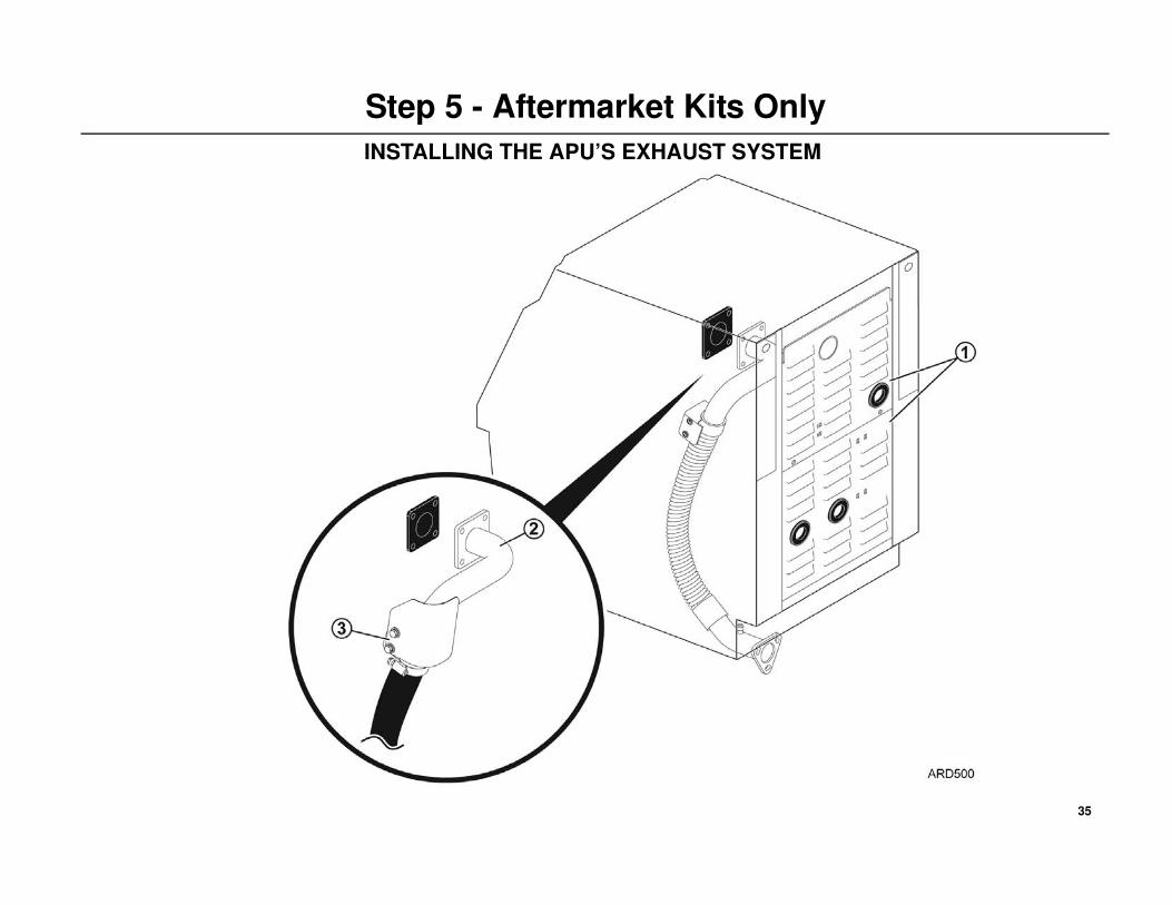
Rear Access Panel
1. Install the new 2 piece rear access panel securely onto the APU.
New Exhaust Components
IMPORTANT: Apply never seize to all stainless steel fasteners.
2. Attach the new exhaust tube assembly onto the exhaust manifold using
the new gasket, washers and nuts supplied. Tighten the mounting
hardware to 15 ft-lb (20 N•m).
3. Secure the new exhaust tube support bracket and heat shield to the
engine’s timing cover using the supplied 3/8'' x 2.5 in. long bolt, washer
and locking nut. Tighten the mounting hardware to 25 ft-lb (34 N•m).
35
Step 5 - Aftermarket Kits Only
INSTALLING THE APU’S EXHAUST SYSTEM
36
Step 6 - Aftermarket Kits Only
INSTALLING APU REAR MOUNTED DPF
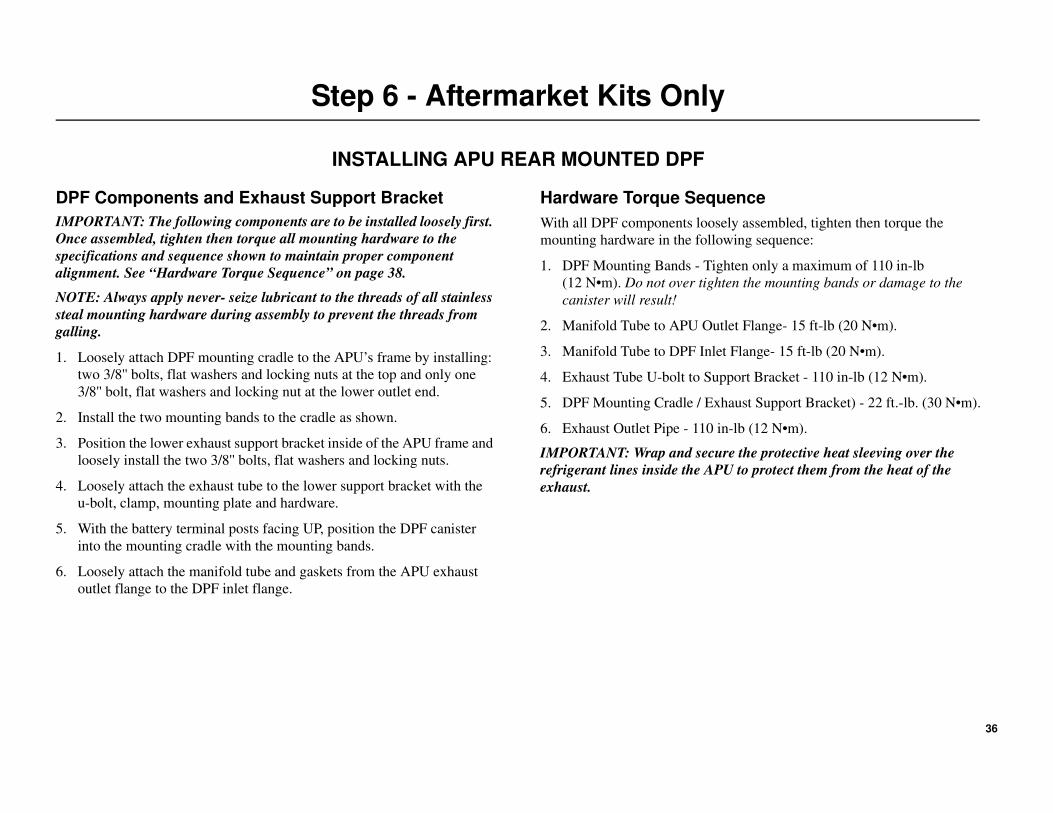
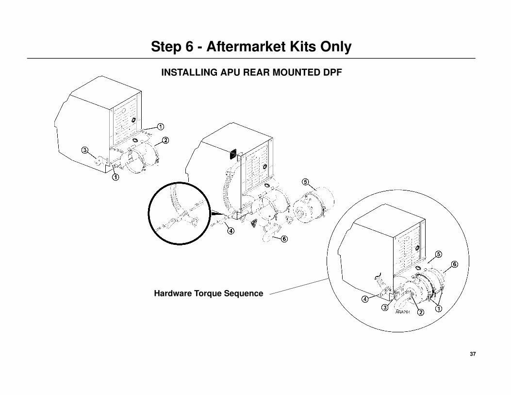
DPF Components and Exhaust Support Bracket
IMPORTANT: The following components are to be installed loosely first.
Once assembled, tighten then torque all mounting hardware to the
specifications and sequence shown to maintain proper component
alignment. See “Hardware Torque Sequence” on page 38.
NOTE: Always apply never- seize lubricant to the threads of all stainless
steal mounting hardware during assembly to prevent the threads from
galling.
1. Loosely attach DPF mounting cradle to the APU’s frame by installing:
two 3/8'' bolts, flat washers and locking nuts at the top and only one
3/8'' bolt, flat washers and locking nut at the lower outlet end.
2. Install the two mounting bands to the cradle as shown.
3. Position the lower exhaust support bracket inside of the APU frame and
loosely install the two 3/8'' bolts, flat washers and locking nuts.
4. Loosely attach the exhaust tube to the lower support bracket with the
u-bolt, clamp, mounting plate and hardware.
5. With the battery terminal posts facing UP, position the DPF canister
into the mounting cradle with the mounting bands.
6. Loosely attach the manifold tube and gaskets from the APU exhaust
outlet flange to the DPF inlet flange.
Hardware Torque Sequence
With all DPF components loosely assembled, tighten then torque the
mounting hardware in the following sequence:
1. DPF Mounting Bands - Tighten only a maximum of 110 in-lb
(12 N•m). Do not over tighten the mounting bands or damage to the
canister will result!
2. Manifold Tube to APU Outlet Flange- 15 ft-lb (20 N•m).
3. Manifold Tube to DPF Inlet Flange- 15 ft-lb (20 N•m).
4. Exhaust Tube U-bolt to Support Bracket - 110 in-lb (12 N•m).
5. DPF Mounting Cradle / Exhaust Support Bracket) - 22 ft.-lb. (30 N•m).
6. Exhaust Outlet Pipe - 110 in-lb (12 N•m).
IMPORTANT: Wrap and secure the protective heat sleeving over the
refrigerant lines inside the APU to protect them from the heat of the
exhaust.
37
Step 6 - Aftermarket Kits Only
INSTALLING APU REAR MOUNTED DPF
Hardware Torque Sequence
38
Step 6a - Installing a Remote Parallel Mounted DPF
DPF Cradle Assembly
1. Align the DPF mounting cradle’s four mounting holes with the four
lower smaller holes on the vertical support bars. NOTE: The notch on
the cradle must face towards the APU as shown in the illustration.
• Install the supplied 3/8'' bolts, washers and locking nuts.
• Tighten the mounting hardware only enough to remove any
excessive play. The hardware will be tightened and torqued in a
later step
2. Install the two DPF mounting bands onto the cradle as shown.
• The DPF cradle assemble is now ready to install onto the frame
using either the claw mount or direct mount method.
Cradle Installation - Claw Mount
IMPORTANT: When spacer bars are used to install the APU to the frame
rail, the correct matching spacer bars must be used to install the DPF.
3. Loosely attach the DPF cradle assembly (with correct matching spacer
bars if applicable) to the tractor’s frame rail with the four mounting
claws, 3/4'' bolts, washers and locking nuts.
• Tighten the mounting hardware only enough to remove any
excessive play.
• The cradle assembly should be allowed to slide freely on the frame
rails for alignment purposes and will be tightened and torqued in a
later step.
Cradle Installation - Direct Mount
IMPORTANT: When spacer bars are used to install the APU to the frame
rail, the correct matching spacer bars must be used to install the DPF.
NOTE: Review the MIN/MAX lengths shown on the DPF Mounting
Configuration drawings on pages14-21 prior to drilling holes in the
tractor’s frame.
4. Using the vertical support bar as reference, measure and mark the
location of the four mounting holes on the tractor’s frame. The new
holes should be at the same height (no higher) then any existing OEM
holes.
• Drill four 13/16 in. (19.8 mm) holes in the frame rail.
5. Attach the DPF cradle assembly (with correct matching spacer bars if
applicable) directly onto the frame rail with four 3/4'' mounting bolts,
washers and locking nuts.
• Torque the four 3/4'' mounting bolts to 100 ft-lb. (135.6 N•m).
DO NOT OVER-TORQUE MOUNTING BOLTS!
DPF Canister Installation
6. Loosely install the DPF canister into the mounting bands with the inlet
flange end facing towards the APU.
• Tighten the mounting bands only enough to remove any excessive
play.
• The DPF canister should be allowed to slide freely in the mounting
bands for alignment purposes and will be tightened in a later step.
39
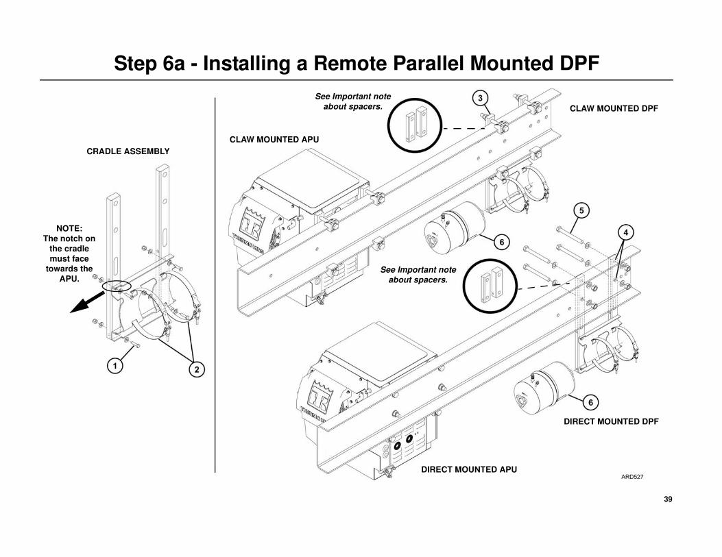
Step 6a - Installing a Remote Parallel Mounted DPF
CRADLE ASSEMBLY
CLAW MOUNTED APU
DIRECT MOUNTED APU
See Important note
about spacers.
See Important note
about spacers.
CLAW MOUNTED DPF
DIRECT MOUNTED DPF
NOTE:
The notch on
the cradle
must face
towards the
APU.
40
Step 6a - Installing a Remote Parallel Mounted DPF
Installing the DPF Exhaust System
IMPORTANT: Always apply never- seize lubricant to the threads of all
stainless steal mounting hardware during assembly to prevent any
galling of the threads.
NOTE: Loosely assemble the entire DPF exhaust system and confirm
proper fit up and alignment before proceeding with the “Hardware
Torque Sequence” on page 44.
1. Attach the exhaust support bracket to the rear of the APU with the
supplied hardware and tighten securely.
2. Loosely attach the short straight exhaust tube flange and gasket onto
the inlet end of the DPF canister with the supplied 3/8'' stainless steel
hardware.
3. Loosely attach one end of the vibrasorber tube onto the short exhaust
tube on the DPF canister with the supplied tube clamp and gasket.
4. Loosely install the manifold tube and gasket to the APU’s exhaust
manifold flange with the supplied 3/8'' stainless steel hardware.
• Loosely attach the APU’s manifold tube directly to the vibrasorber
tube with the supplied tube clamp and gasket.
• If the distance from the APU to the DPF does not allow the outlet
tube to be connected directly to the vibrasorber, the supplied
extension tube and support bracket will need to be installed. See
steps #5 and #6.
Extension Tube
NOTE: An extension tube is required when the distance from the APU to
the DPF does not allow the outlet tube to be connected directly to the
vibrasorber. The tube is supplied in the installation kit and will need to be
cut to fit your particular installation.
5. Long Extension Tube Modifications - Loosely attach the large clamp
end of the 36'' (914.4 mm) extension tube onto the end of the exhaust
tube elbow with the supplied clamp.
• Measure and mark the small straight end of the extension tube
where it will attach to the vibrasorber tube.
• Remove the extension tube and cut it squarely at the measurement
indicated and remove any burrs from the end of the tube.
• Loosely reinstall the large clamp end of the extension tube back
onto the elbow tube using the supplied tube clamp and gasket.
• Position the exhaust support assembly onto the frame rail and
loosely install the U-bolt and mounting hardware around and
exhaust tube and through the support bracket. Proceed to
“Hardware Torque Sequence” on page 44.
Frame Mounted Support Bracket6. If the exhaust extension tube remains 36'' (914.4 mm) long, the
additional frame mounted support bracket supplied must be installed to
provide adequate support to the exhaust system.
41
Step 6a - Installing a Remote Parallel Mounted DPF
42
Step 6a - Installing a Remote Parallel Mounted DPF
Hardware Torque Sequence
With all DPF components loosely assembled, tighten then torque the
mounting hardware in the following sequence:
1. DPF Mounting Bands - Tighten only a maximum of 110 in-lb
(12 N•m). Do not over tighten the mounting bands or damage to the
canister will result!
2. Short Tube with Flange to DPF Canister - 15 ft-lb (20 N•m).
3. Manifold Tube to APU Exhaust Flange - 15 ft-lb (20 N•m).
4. DPF Mounting Cradle - 22 ft-lb (30 N•m)..
IMPORTANT: DO NOT OIL THE BOLT THREADS!
5. With the DPF in the proper location on the frame rail:
• Push the support bars (and spacer blocks if applicable) up tight to
the tractor frame.
• Confirm the top and bottom mounting claws and bolts are
positioned flat on the frame. Tighten the mounting hardware only
enough to remove excess play.
• Using a torque wrench, torque the mounting claw bolts in four step
increments starting with the top bolts, then the bottom bolts.
STEP 1- Torque the top then the bottom mounting bolts to 25 ft-lb.
(33.9 N•m).
IMPORTANT: STOP and verify all mounting claws and bolts
remained flat on the frame (Detail A). If they are not, loosen bolts,
adjust as necessary and retighten again to 25 ft-lb. (33.9 N•m).
STEP 2- After the first step is successfully completed, torque the top
then the bottom bolts to 50 ft-lb. (67.8 N•m).
STEP 3- Next, torque the top and then the bottom bolts to 100 ft-lb.
(135.6 N•m).
STEP 4 - Finally, recheck all bolts to confirm they are at 100 ft-lb.
(135.6 N•m)
IMPORTANT: DO NOT OVER-TORQUE MOUNTING BOLTS!
6. Exhaust Clamps - 40.5 ft-lb (55 N•m).
7. U-bolt Clamp to APU Support Bracket - 110 in-lb (12 N•m).
8. (Optional) Exhaust Hanger Support Bracket to Frame Rail
• Tighten 3/8'' hardware on the clamp to the frame rail to
22 ft-lb (30 N•m).
• Tighten the 1/4'' hardware on the hanger strap to 5 ft-lb (6.7 N•m).
• Tighten the 5/16'' U-bolts to 110 in-lb (12 N•m).
9. Exhaust Outlet Pipe - 110 in-lb (12 N•m).
WARNING: The following steps are critical and must be followed
to ensure the safe installation of the DPF to the tractor’s frame.
43
Step 6a - Installing a Remote Parallel Mounted DPF
44
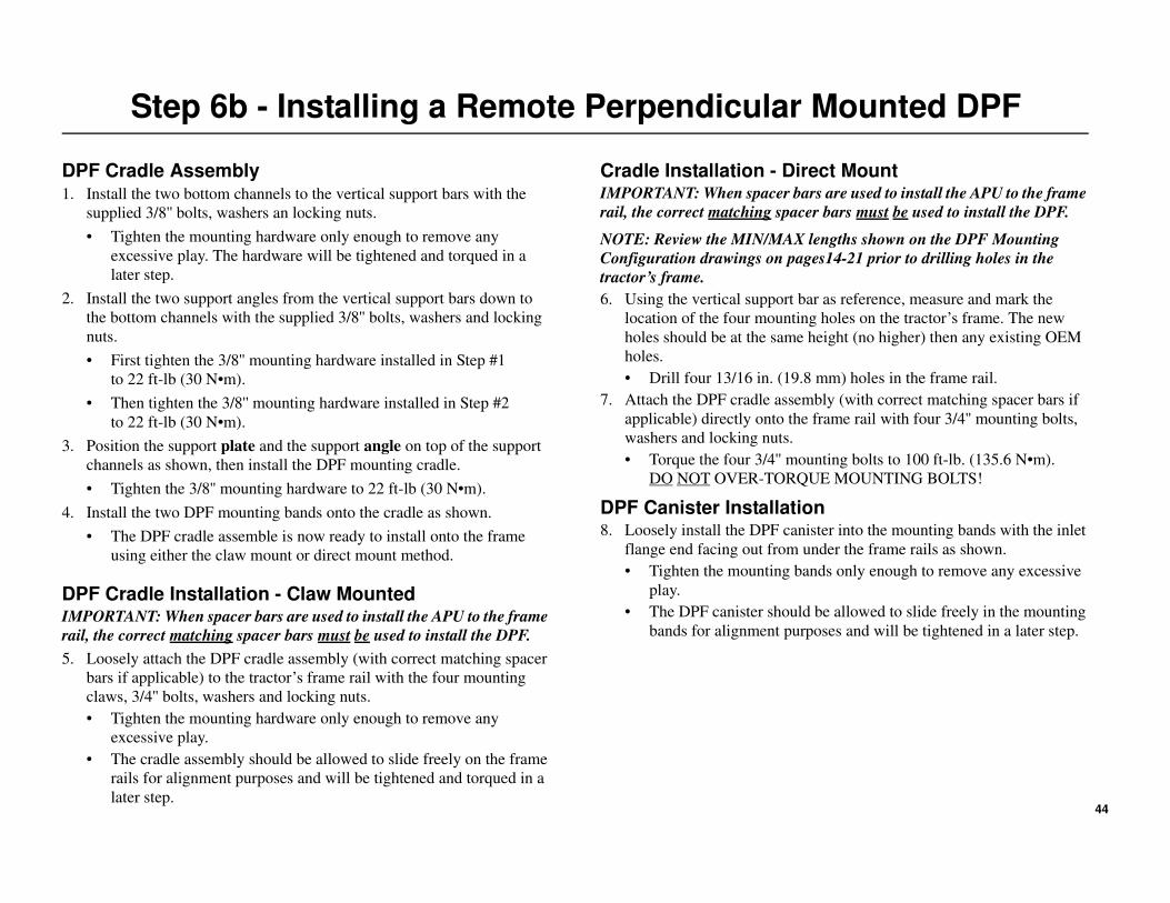
Step 6b - Installing a Remote Perpendicular Mounted DPF
DPF Cradle Assembly1. Install the two bottom channels to the vertical support bars with the
supplied 3/8'' bolts, washers an locking nuts.
• Tighten the mounting hardware only enough to remove any
excessive play. The hardware will be tightened and torqued in a
later step.
2. Install the two support angles from the vertical support bars down to
the bottom channels with the supplied 3/8'' bolts, washers and locking
nuts.
• First tighten the 3/8'' mounting hardware installed in Step #1
to 22 ft-lb (30 N•m).
• Then tighten the 3/8'' mounting hardware installed in Step #2
to 22 ft-lb (30 N•m).
3. Position the support plate and the support angle on top of the support
channels as shown, then install the DPF mounting cradle.
• Tighten the 3/8'' mounting hardware to 22 ft-lb (30 N•m).
4. Install the two DPF mounting bands onto the cradle as shown.
• The DPF cradle assemble is now ready to install onto the frame
using either the claw mount or direct mount method.
DPF Cradle Installation - Claw MountedIMPORTANT: When spacer bars are used to install the APU to the frame
rail, the correct matching spacer bars must be used to install the DPF.
5. Loosely attach the DPF cradle assembly (with correct matching spacer
bars if applicable) to the tractor’s frame rail with the four mounting
claws, 3/4'' bolts, washers and locking nuts.
• Tighten the mounting hardware only enough to remove any
excessive play.
• The cradle assembly should be allowed to slide freely on the frame
rails for alignment purposes and will be tightened and torqued in a
later step.
Cradle Installation - Direct MountIMPORTANT: When spacer bars are used to install the APU to the frame
rail, the correct matching spacer bars must be used to install the DPF.
NOTE: Review the MIN/MAX lengths shown on the DPF Mounting
Configuration drawings on pages14-21 prior to drilling holes in the
tractor’s frame.
6. Using the vertical support bar as reference, measure and mark the
location of the four mounting holes on the tractor’s frame. The new
holes should be at the same height (no higher) then any existing OEM
holes.
• Drill four 13/16 in. (19.8 mm) holes in the frame rail.
7. Attach the DPF cradle assembly (with correct matching spacer bars if
applicable) directly onto the frame rail with four 3/4'' mounting bolts,
washers and locking nuts.
• Torque the four 3/4'' mounting bolts to 100 ft-lb. (135.6 N•m).
DO NOT OVER-TORQUE MOUNTING BOLTS!
DPF Canister Installation8. Loosely install the DPF canister into the mounting bands with the inlet
flange end facing out from under the frame rails as shown.
• Tighten the mounting bands only enough to remove any excessive
play.
• The DPF canister should be allowed to slide freely in the mounting
bands for alignment purposes and will be tightened in a later step.
45
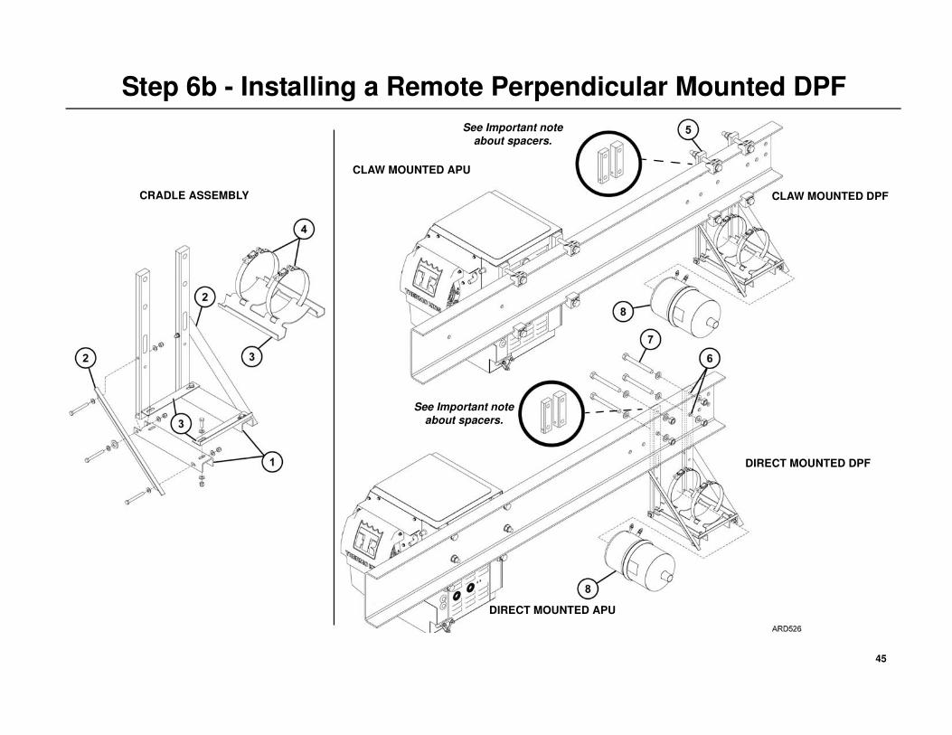
Step 6b - Installing a Remote Perpendicular Mounted DPF
CRADLE ASSEMBLY
CLAW MOUNTED APU
See Important note
about spacers.
See Important note
about spacers.
CLAW MOUNTED DPF
DIRECT MOUNTED DPF
DIRECT MOUNTED APU
46
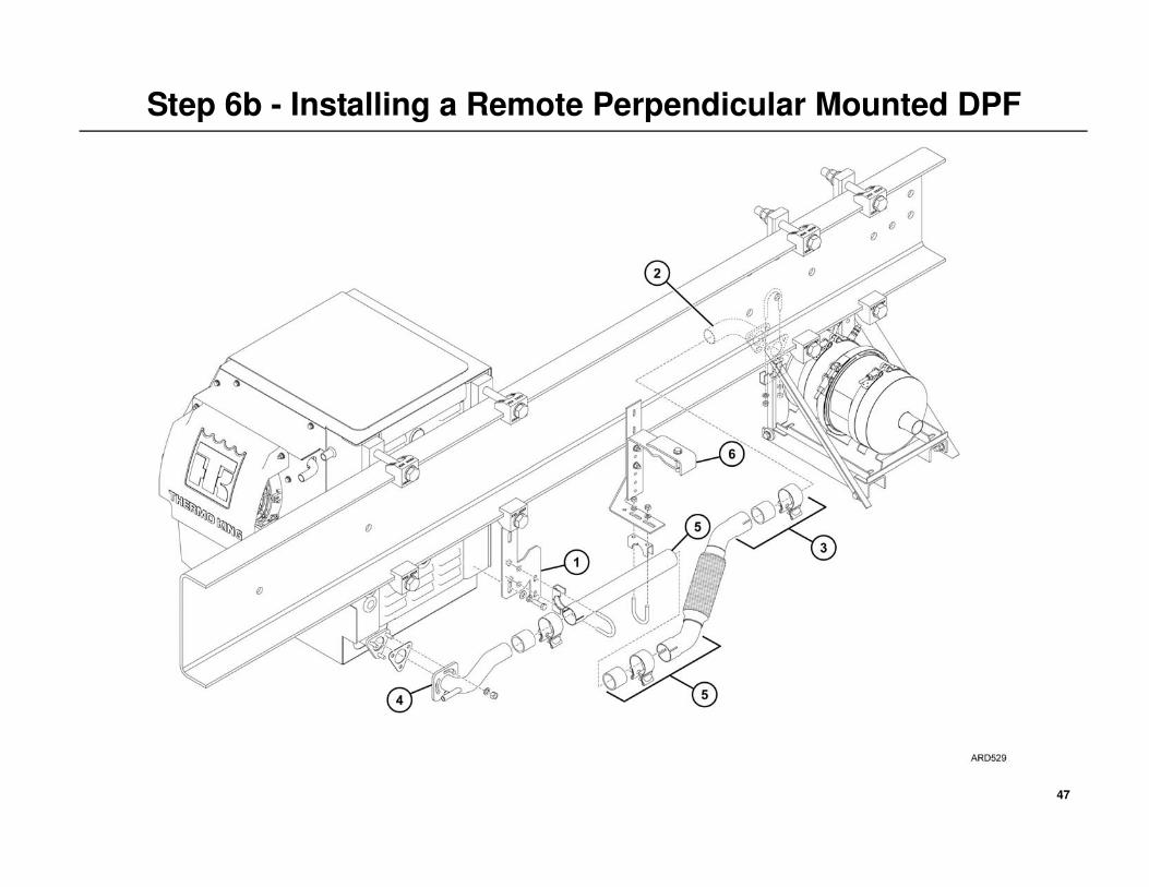
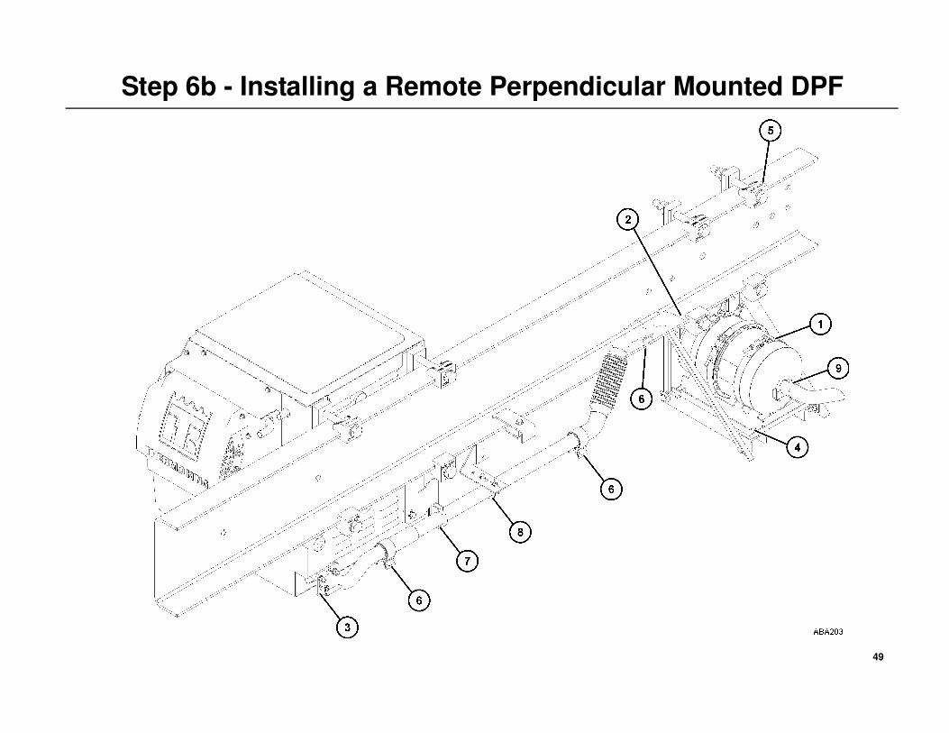
Step 6b - Installing a Remote Perpendicular Mounted DPF
Installing the DPF Exhaust System
IMPORTANT: Always apply never- seize lubricant to the threads of all
stainless steal mounting hardware during assembly to prevent any
galling of the threads.
NOTE: Loosely assemble the entire DPF exhaust system and confirm
proper fit up and alignment before proceeding with the “Hardware
Torque Sequence” on page 50.
1. Attach the exhaust support bracket to the rear of the APU with the
supplied hardware and tighten securely.
2. Loosely attach the short 90 degree exhaust tube flange and gasket onto
the inlet end of the DPF canister with the supplied 3/8'' stainless steel
hardware.
3. Loosely attach one end of the vibrasorber tube onto the short exhaust
tube on the DPF canister with the supplied tube clamp and gasket.
4. Loosely install the manifold tube and gasket to the APU’s exhaust
manifold flange with the supplied 3/8'' stainless steel hardware.
• Loosely attach the APU’s outlet tube directly to the vibrasorber
tube with the supplied tube clamp and gasket.
• If the distance from the APU to the DPF does not allow the outlet
tube to be connected directly to the vibrasorber, the supplied
extension tube and support bracket will need to be installed. See
steps #5 and #6.
Extension Tube
NOTE: An extension tube is required when the distance from the APU to
the DPF does not allow the outlet tube to be connected directly to the
vibrasorber. The tube is supplied in the installation kit and will need to be
cut to fit your particular installation.
5. Long Extension Tube Modifications - Loosely attach the large clamp
end of the 36'' (914.4 mm) extension tube onto the end of the exhaust
tube elbow with the supplied clamp.
• Measure and mark the small straight end of the extension tube
where it will attach to the vibrasorber tube.
• Remove the extension tube and cut it squarely at the measurement
indicated and remove any burrs from the end of the tube.
• Loosely reinstall the large clamp end of the extension tube back
onto the elbow tube using the supplied tube clamp and gasket.
• Position the exhaust support assembly onto the frame rail and
loosely install the U-bolt and mounting hardware around and
exhaust tube and through the support bracket.
Frame Mounted Support Bracket6. If the exhaust extension tube remains 36'' (914.4 mm) long, the
additional frame mounted support bracket supplied must be installed to
provide adequate support to the exhaust system.
47
Step 6b - Installing a Remote Perpendicular Mounted DPF
48
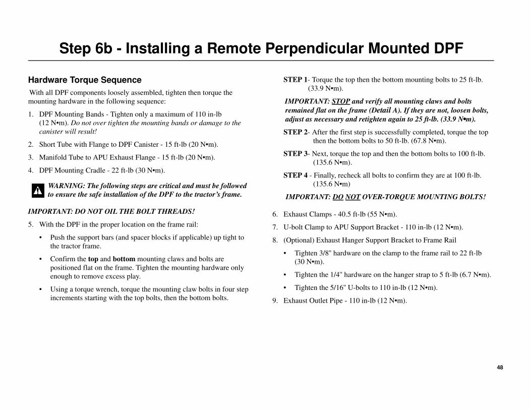
Step 6b - Installing a Remote Perpendicular Mounted DPF
Hardware Torque Sequence
With all DPF components loosely assembled, tighten then torque the
mounting hardware in the following sequence:
1. DPF Mounting Bands - Tighten only a maximum of 110 in-lb
(12 N•m). Do not over tighten the mounting bands or damage to the
canister will result!
2. Short Tube with Flange to DPF Canister - 15 ft-lb (20 N•m).
3. Manifold Tube to APU Exhaust Flange - 15 ft-lb (20 N•m).
4. DPF Mounting Cradle - 22 ft-lb (30 N•m).
IMPORTANT: DO NOT OIL THE BOLT THREADS!
5. With the DPF in the proper location on the frame rail:
• Push the support bars (and spacer blocks if applicable) up tight to
the tractor frame.
• Confirm the top and bottom mounting claws and bolts are
positioned flat on the frame. Tighten the mounting hardware only
enough to remove excess play.
• Using a torque wrench, torque the mounting claw bolts in four step
increments starting with the top bolts, then the bottom bolts.
STEP 1- Torque the top then the bottom mounting bolts to 25 ft-lb.
(33.9 N•m).
IMPORTANT: STOP and verify all mounting claws and bolts
remained flat on the frame (Detail A). If they are not, loosen bolts,
adjust as necessary and retighten again to 25 ft-lb. (33.9 N•m).
STEP 2- After the first step is successfully completed, torque the top
then the bottom bolts to 50 ft-lb. (67.8 N•m).
STEP 3- Next, torque the top and then the bottom bolts to 100 ft-lb.
(135.6 N•m).
STEP 4 - Finally, recheck all bolts to confirm they are at 100 ft-lb.
(135.6 N•m)
IMPORTANT: DO NOT OVER-TORQUE MOUNTING BOLTS!
6. Exhaust Clamps - 40.5 ft-lb (55 N•m).
7. U-bolt Clamp to APU Support Bracket - 110 in-lb (12 N•m).
8. (Optional) Exhaust Hanger Support Bracket to Frame Rail
• Tighten 3/8'' hardware on the clamp to the frame rail to 22 ft-lb
(30 N•m).
• Tighten the 1/4'' hardware on the hanger strap to 5 ft-lb (6.7 N•m).
• Tighten the 5/16'' U-bolts to 110 in-lb (12 N•m).
9. Exhaust Outlet Pipe - 110 in-lb (12 N•m).
WARNING: The following steps are critical and must be followed
to ensure the safe installation of the DPF to the tractor’s frame.
49
Step 6b - Installing a Remote Perpendicular Mounted DPF
50
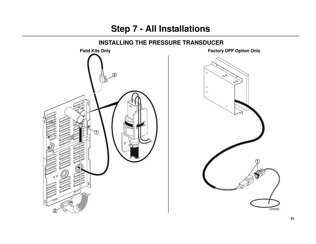
Step 7 - All Installations
INSTALLING THE PRESSURE TRANSDUCER
Field Kits Only
NOTE: The new rear access panel should have been installed (see Step 5)
onto the APU. It is only shown not installed for clarity.
1. Locate the pressure transducer, hose and stainless steel tube
pre-assembled on the new rear access panel.
2. Attach the stainless steel tube and fitting from the transducer onto the
the exhaust tube by:
• Loosening the lower hose clamp of short length of 1/4 '' I.D.
silicone high temperature hose attached to the stainless steel tube.
• Pulling the steel tube down to the fitting on the exhaust tube and
tightening the fitting securely.
• Re-tightening the hose clamp securely.
3. Route the 3-Pin connector from the transducer harness (coming from
the cab) through the grommet in the access panel and attach it to the
transducer.
• Lock the transducer connector in place with the locking pin and
secure the harness to bracket with tie bands.
Factory DPF Option Only
NOTE: The pressure transducer, hose and stainless steel tube is already
factory installed onto the APU’s exhaust tube.
1. Route the 3-Pin connector (EPN, EPI, P) from the pressure transducer
harness (coming from the APU) up through the access hole and into the
tractor.
• Attach the connector to the mating 3-pin connector from the DPF
Controller.
• Secure the harness with tie bands.
• Apply sealer around the access hole.
51
Step 7 - All Installations
INSTALLING THE PRESSURE TRANSDUCER
Field Kits Only Factory DPF Option Only
52
Step 8 - All Installations
INSTALLING THE AIR INTAKE HOSE
Field Kits Only
1. Install the new air cleaner assembly onto the engine.
NOTE: The old style air filter assembly has a screen located inside
the fitting. This screen will not provide the required air flow to the air
motor. A new air cleaner assembly is supplied in the kit that does not
have this screen. This new air cleaner assembly must be installed to
provide the correct air flow to the air motor.
2. Route the short 6 ft. (1.8 m) black 1/2'' I.D. rubber hose behind the
DPF canister, through the grommet in the rear access panel and into the
APU. Attach the hose to the nipple fitting on the air cleaner and secure
with the hose clamp.
3. Locate the long 40 ft. (12 m) black 1/2'' I.D. hose and insert one end of
the hose up into the access hole in the bottom of the valve box 3'' inches
(76 mm) and tighten the connector body.
• Route the other end of the long black 1/2'' hose from the valve box
down to the short black 1/2'' hose at the back of the APU.
4. Water Trap - Before connecting the two air intake hoses, determine
the lowest point the air intake hose will be at when installed onto the
APU.
• At the hoses lowest point, cut and connect the two black 1/2'' hoses
together with the supplied tee fitting and clamps.
• Retain the excess hose for use later.
• Cut and attach a short 6'' (152 mm) length of black 1/2'' I.D. hose
onto the tee fitting and then install the supplied plug into the end of
the hose.
IMPORTANT: Be sure the air intake hose is routed with a continuous
downward slope with no sharp bends or kinks and is secured adequately.
Factory DPF Option Only
1. Locate the long 40 ft. (12 m) black 1/2'' I.D. hose and insert one end of
the hose up into the access hole in the bottom of the valve box 3'' inches
(76 mm) and tighten the connector body.
• Route the other end of the long black 1/2'' hose from the valve box
down to the short black 1/2'' hose at the back of the APU.
2. Water Trap - Before connecting the two air intake hoses, determine
the lowest point the air intake hose will be at when installed onto the
APU.
• At the lowest point, cut and connect the two black 1/2'' hoses
together with the supplied tee fitting and clamps. Retain the excess
hose for use in step 4.
• Cut and attach a short 6'' (152 mm) length of black 1/2'' I.D. hose
onto the tee fitting and then install the supplied plug into the end of
the hose.
IMPORTANT: Be sure the air intake hose is routed with a continuous
downward slope with no sharp bends or kinks and is secured adequately.
53
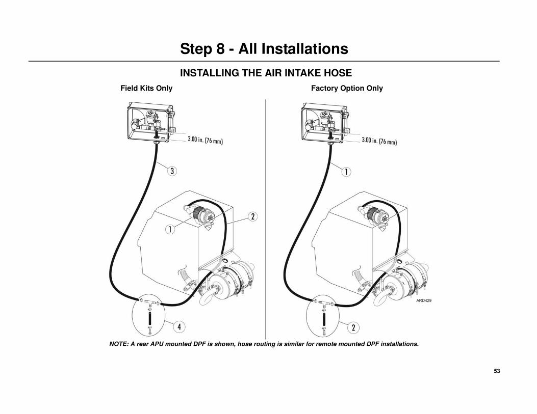
Step 8 - All Installations
Field Kits Only Factory Option Only
NOTE: A rear APU mounted DPF is shown, hose routing is similar for remote mounted DPF installations.
INSTALLING THE AIR INTAKE HOSE
54
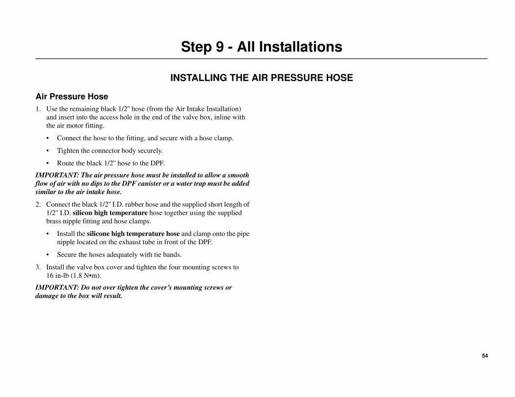
Step 9 - All Installations
INSTALLING THE AIR PRESSURE HOSE
Air Pressure Hose
1. Use the remaining black 1/2'' hose (from the Air Intake Installation)
and insert into the access hole in the end of the valve box, inline with
the air motor fitting.
• Connect the hose to the fitting, and secure with a hose clamp.
• Tighten the connector body securely.
• Route the black 1/2'' hose to the DPF.
IMPORTANT: The air pressure hose must be installed to allow a smooth
flow of air with no dips to the DPF canister or a water trap must be added
similar to the air intake hose.
2. Connect the black 1/2'' I.D. rubber hose and the supplied short length of
1/2'' I.D. silicon high temperature hose together using the supplied
brass nipple fitting and hose clamps.
• Install the silicone high temperature hose and clamp onto the pipe
nipple located on the exhaust tube in front of the DPF.
• Secure the hoses adequately with tie bands.
3. Install the valve box cover and tighten the four mounting screws to
16 in-lb (1.8 N•m).
IMPORTANT: Do not over tighten the cover’s mounting screws or
damage to the box will result.
55
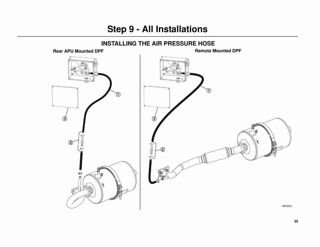
Step 9 - All Installations
INSTALLING THE AIR PRESSURE HOSE
Rear APU Mounted DPF Remote Mounted DPF
56
Step 10 - All Installations
INSTALLING THE EXHAUST TUBE
Rear APU Mounted DPF
Install the exhaust tail tube onto the DPF canister and secure to the side of
the APU with the muffler clamp and bracket.
• Tighten the muffler clamp to 110 in-lb (12N•m).
Remote Mounted DPF
Install the exhaust tube onto the DPF canister facing out from under the
chassis.
• Tighten the clamp to 110 in-lb (12N•m).
57
Step 10 - All Installations
INSTALLING THE EXHAUST TUBE
Rear APU Mounted DPF Remote Mounted DPF
58
Step 11 - All Installations
ELECTRICAL CONNECTIONS
Important Battery Cable Installation Information
See “Battery Cable Installation and Routing” on page 7 for additional
information.
Battery Cables to DPF Connections
IMPORTANT: Battery cable lugs must be attached securely to the battery
cable using the proper terminal lug crimping tool. The lugs should be
pull tested to confirm they are secure on the battery cable.
IMPORTANT: Superlube(203-524) or equivalent should be applied to all
electrical connections.
Battery Cables to DPF Connections
NOTE: The battery cables and mounting hardware must be installed
onto the DPF and torqued exactly as shown.
1. Route the Positive Cable (from the valve box) to the DPF.
IMPORTANT: DO NOT CUT THIS CABLE! The length of this cable
is critical to the proper operation of the DPF.
• Slide the protective boot over the positive cable and attach the cable
onto the positive post of the DPF canister.
IMPORTANT: The mounting hardware must be installed in the
correct order and torqued exactly as shown.
• Position the protective boot over the terminal nut and post.
2. Bundle the excess length of the positive cable neatly and securely to the
tractor’s frame.
3. Route the Negative Battery Cable (from the battery) along with the
Ground Harness (CH-09 from the Controller Harness) to the DPF.
• Cut the battery cable to the correct length and attach the heat shrink
and terminal lug.
• Slide the protective boot over the battery cable and the ground
harness terminal ring (CH-09).
• Attach both the negative battery cable lug and the terminal ring
(CH-09) onto the negative post of the DPF canister.
IMPORTANT: The mounting hardware must be installed in the
correct order and torqued exactly as shown.
• Position the protective boot over the terminal nut and post.
4. Secure all cables and harness adequately with tie bands.
5. Seal any access holes made in the floor of the tractor.
Battery Cable to In-Line Fuse Connections6. Set all APU HMI controls to the OFF position and reinstall the APU’s
positive battery cable.
7. Attach one end of the 12 in. (305 mm) positive battery cable onto the
open end of the fuse holder and the other end onto the positive post of
the battery and tighten connections securely.
8. Verify the following electrical connections are clean and tight:
POSITIVE CABLES
a. Battery to Fuse
b. Fuse to Contactor
c. Contactor to DPF Positive Stud
NEGATIVE CABLES
d. Battery to DPF Negative Stud
59
Step 11 - All Installations
FACTORY INSTALLED
Nut - Torqued to 108 in-lb (12 N•m)
Split Lock Washer
Washer
Protective Boot
IMPORTANT HARDWARE
INSTALLATION STACKUP
Nut - Torque to 108 in-lb (12 N•m)
Washer
Positive Battery Cable
Internal Tooth Lock WasherNut - Torque to 108 in-lb (12 N•m)
Protective Boot
Washer
Negative Battery Cable and
Ground Terminals
Internal Tooth Lock Washer
FACTORY INSTALLED
Nut - Torqued to 108 in-lb (12 N•m)
ELECTRICAL CONNECTIONS
IMPORTANT: DO NOT CUT THIS CABLE!
The length of this cable is critical to the proper
operation of the DPF. Bundle the excess length of
the positive cable neatly and securely to the tractor’s
frame.
60
Step 12 - All Installations
DPF TEST PROCEDURES
Procedures
Confirm the individual DPF components are connected and operate by
initiating a System Test Mode. The test mode takes 60 seconds to
complete: the first 30 seconds of the test will operate the Regen Switch,
Exhaust Monitor and both the Blower Motor and Air Valve, while the last
30 seconds will operate all the components as well as the DPF heater.
Before beginning the test, attach a voltmeter onto the positive and negative
battery connections on the DPF canister.
1. Place the Regeneration switch to the “center” on position.
2. Turn the HMI controls on and set the APU to operate.
3. Before the APU engine starts, set the DPF into System Test Mode by
pressing the REGEN Switch 3 times (one second pulses) within 10
seconds. You need to have one second ON and one second OFF to
count as a pulse.
First 30 seconds of the test verify the following:
• the solid amber indicator light on the REGEN switch is
illuminated
• both the amber and red indicator lights on the exhaust monitor
are illuminated
• both the blower and air valve are operating.
Last 30 seconds of the test verify the following:
• battery voltage is present at the DPF terminal posts.
4. DPF System Test Mode will shutoff after 60 seconds. Verify no fault
codes (flashing RED indicator lights) have been set.
APU Exhaust System Check
1. Turn the HMI controls on and set the APU to operate.
2. Run the APU and check all exhaust connections for leaks.
3. If any leaks are found, tighten connections securely.
61
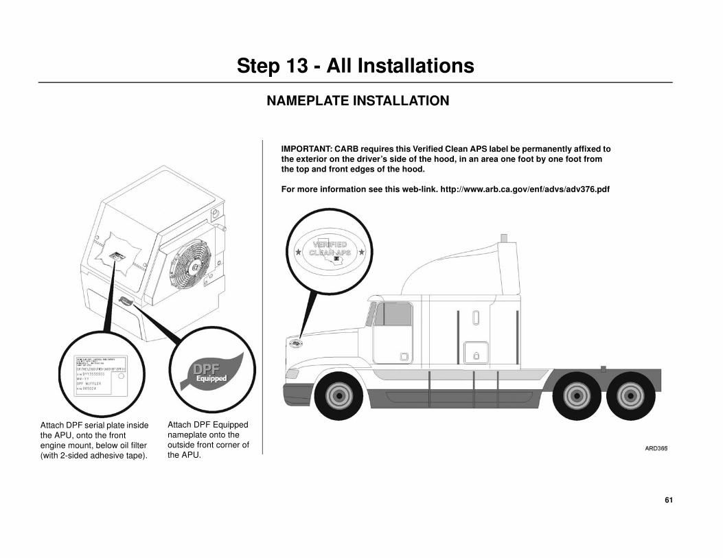
Step 13 - All Installations
Attach DPF serial plate inside
the APU, onto the front
engine mount, below oil filter
(with 2-sided adhesive tape).
Attach DPF Equipped
nameplate onto the
outside front corner of
the APU.
IMPORTANT: CARB requires this Verified Clean APS label be permanently affixed to
the exterior on the driver’s side of the hood, in an area one foot by one foot from
the top and front edges of the hood.
For more information see this web-link. http://www.arb.ca.gov/enf/advs/adv376.pdf
NAMEPLATE INSTALLATION
68
All Installations
IMPORTANT APU ENGINE OPERATING REQUIREMENTS
Engine Operation
The engine must be maintained according to Thermo King’s
recommendations for air cleaner change interval, oil change interval, and
other service related items as outlined in the TriPac Operators Manual
TK-53035 or the TriPac DPF Operators Manual TK-53925.
Diesel Fuel
• Use Ultra Low Sulphur Diesel (ULSD) fuel which has 15 ppm
sulfur content or lower.
• No additional fuel additives are required for proper operation of
this filter.
• Do not mix lube oil with the fuel in any concentration. The lube oil
in the fuel will result in premature clogging of the DPF.
Engine Oil
• Engine oil consumption rate should be less than 1.1 quarts (1.0
liters) per 200 hours, or 0.28 quarts (0.25 liters) per 50 hours. If the
engine oil consumption rate is higher, service the engine as needed
to reduce the oil consumption rate. A high oil consumption rate can
cause premature clogging of the DPF.
• Use only CJ-4 or better oil.
Injectors
• Injectors must be serviced at time of the DPF installation if they
have not been serviced within the past 3000 engine hours. In
addition, injectors must be serviced at 3000 engine hour
maintenance intervals to maintain proper combustion and proper
operation of the DPF.
69
Aftermarket Kits Only
ENGINE INSPECTION CHECK LIST
A Thermo King dealer or certified TriPac installer, under the guidance and training of Thermo King Corp, must review actual operating conditions (e.g. lube
oil consumption, injector service) prior to retrofitting an engine with the Thermo King DPF to determine if the candidate engine is suitable for installation of a
DPF. Please note that Thermo King provides training for installers, on an as-needed basis. The results must be recorded on the attached Engine Inspection
Check List and retained by the Thermo King dealer or certified installer for a minimum of 3-years (warranty period).
1. Engine oil consumption rate should be less than 1.1 quarts (1.0 liters) per 200 hours, or 0.28 quarts (0.25 liters) per 50 hours. If the engine oil consumption
rate is higher, service the engine as needed to reduce the oil consumption rate. A high oil consumption rate can cause premature clogging of the DPF. For
complete approval of the installation of this filter system, the customer must provide the known oil consumption rate for this APU.
2. Injectors must be serviced at time of filter installation, if they have not been serviced within the past 3000 engine hours. In addition, injectors must be
serviced at 3000 engine hour maintenance intervals to maintain proper combustion and proper operation of the filter. For complete approval of the
installation of this filter system, the Thermo King dealer / certified installer must confirm that injector service has been performed as required above, and
as described in the Thermo King maintenance manual.
3. The APU engine must be maintained according to the manufacturer’s recommendations for air cleaner change interval, oil change interval, and crankcase
pressure as outlined in the APU service and maintenance manuals. For complete approval of the installation of this DPF system, the Thermo King
dealer/installer must confirm that the air cleaner has been changed, the oil has been changed, and the crankcase pressure has been checked according to the
maintenance schedule for the APU. Thermo King dealer / certified installer shall initial the Inspection Checklist to confirm that all the above-mentioned
service has been performed per the APU owner’s manual.
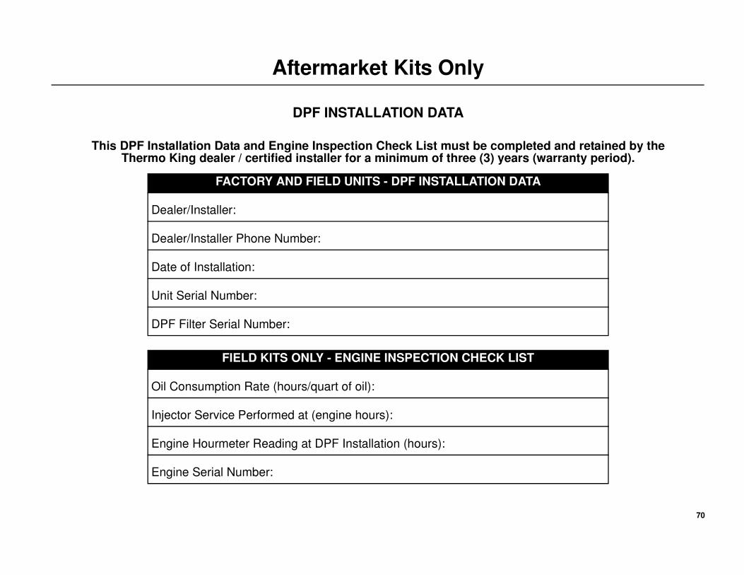
70
Aftermarket Kits Only
DPF INSTALLATION DATA
This DPF Installation Data and Engine Inspection Check List must be completed and retained by the Thermo King dealer / certified installer for a minimum of three (3) years (warranty period).
FACTORY AND FIELD UNITS - DPF INSTALLATION DATA
Dealer/Installer:
Dealer/Installer Phone Number:
Date of Installation:
Unit Serial Number:
DPF Filter Serial Number:
FIELD KITS ONLY - ENGINE INSPECTION CHECK LIST
Oil Consumption Rate (hours/quart of oil):
Injector Service Performed at (engine hours):
Engine Hourmeter Reading at DPF Installation (hours):
Engine Serial Number:

Installation Manual
Providing equipment and services to manage controlled-temperature environments for food and other temperature-sensitive products, our Climate Control Technologies sector encompasses both transport and stationary refrigeration solutions. Our product brands include Thermo King®, a world leader in transport temperature control systems, and Hussmann®, a manufacturer of refrigeration and food merchandising equipment.
www.thermoking.com www.hussmann.com www.ingersollrand.com
©2008 Ingersoll-Rand Company Printed in U.S.A. on Recycled Paper
TriPac Diesel Particulate Filter (DPF)Factory and Aftermarket - APU Rear Mounted DPF Installations
Factory and Aftermarket - APU Remote Mounted DPF Installations
TK 53766-19-IM (Rev. 6, 01/12)