Embed Size (px)
Citation preview

Goulds Pumps
Installation, Operation, andMaintenance Manuali-ALERT™ Condition Monitor

Table of Contents
Introduction and Safety...................................................................................................................................................2Introduction.......................................................................................................................................................................2
Requesting other information......................................................................................................................................2Inspect the package........................................................................................................................................................2Product warranty............................................................................................................................................................2
Safety...................................................................................................................................................................................3Safety terminology and symbols..................................................................................................................................3Safety regulations for Ex-approved products in potentially explosive atmospheres...........................................4
Product approval standards.............................................................................................................................................5Certificates of conformance............................................................................................................................................7
Product Description........................................................................................................................................................13General description i-ALERT™ Condition Monitor................................................................................................13
Installation.........................................................................................................................................................................14Attach the i-ALERT™ Condition Monitor to the pump..........................................................................................14
Commissioning, Startup, Operation, and Shutdown............................................................................................15Activate the i-ALERT™ Condition Monitor..............................................................................................................15i-ALERT™ Condition Monitor routine operation....................................................................................................16Deactivate the i-ALERT™ Condition Monitor..........................................................................................................16Reset the i-ALERT™ Condition Monitor...................................................................................................................16
Maintenance......................................................................................................................................................................17Guidelines for i-ALERT™ Condition Monitor disposal..........................................................................................17
Troubleshooting...............................................................................................................................................................18i-ALERT™ Condition Monitor troubleshooting.......................................................................................................18
Local ITT Contacts.........................................................................................................................................................19Regional offices................................................................................................................................................................19
Table of Contents
i-ALERT™ Condition Monitor Installation, Operation, and Maintenance Manual 1
Introduction and SafetyIntroductionPurpose of this manual
The purpose of this manual is to provide necessary information for:• Installation• Operation• Maintenance
CAUTION:Read this manual carefully before installing and using the product. Improper use of the product can causepersonal injury and damage to property, and may void the warranty.
NOTICE:Save this manual for future reference, and keep it readily available at the location of the unit.
Requesting other informationSpecial versions can be supplied with supplementary instruction leaflets. See the sales contract for anymodifications or special version characteristics. For instructions, situations, or events that are notconsidered in this manual or in the sales documents, please contact the nearest ITT representative.Always specify the exact product type and identification code when requesting technical information orspare parts.
Inspect the package1. Inspect the package for damaged or missing items upon delivery.2. Note any damaged or missing items on the receipt and freight bill.3. File a claim with the shipping company if anything is out of order.
If the product has been picked up at a distributor, make a claim directly to the distributor.
Product warrantyCoverage
ITT undertakes to remedy faults in products from ITT under these conditions:• The faults are due to defects in design, materials, or workmanship.• The faults are reported to an ITT representative within the warranty period.• The product is used only under the conditions described in this manual.• The monitoring equipment incorporated in the product is correctly connected and in use.• All service and repair work is done by ITT-authorized personnel.• Genuine ITT parts are used.• Only Ex-approved spare parts and accessories authorized by ITT are used in Ex-approved products.
LimitationsThe warranty does not cover faults caused by these situations:
• Deficient maintenance• Improper installation• Modifications or changes to the product and installation made without consulting ITT• Incorrectly executed repair work• Normal wear and tear
Introduction and Safety
2 i-ALERT™ Condition Monitor Installation, Operation, and Maintenance Manual
ITT assumes no liability for these situations:• Bodily injuries• Material damages• Economic losses
Warranty claimITT products are high-quality products with expected reliable operation and long life. However, should theneed arise for a warranty claim, then contact your ITT representative.
SafetyWARNING:
• The operator must be aware of safety precautions to prevent physical injury.• Any pressure-containing device can explode, rupture, or discharge its contents if it is over-pressurized.
Take all necessary measures to avoid over-pressurization.• Operating, installing, or maintaining the unit in any way that is not covered in this manual could cause
death, serious personal injury, or damage to the equipment. This includes any modification to theequipment or use of parts not provided by ITT. If there is a question regarding the intended use ofthe equipment, please contact an ITT representative before proceeding.
• Installation, Operation, and Maintenance manuals clearly identify accepted methods for disassemblingunits. These methods must be adhered to. Trapped liquid can rapidly expand and result in a violentexplosion and injury. Never apply heat to impellers, propellers, or their retaining devices to aid in theirremoval.
• Do not change the service application without the approval of an authorized ITT representative.• Never operate the pump below the minimum rated flow, when dry, or without prime.• Never operate the pump without safety devices installed.• Never operate the pump with the discharge valve closed.• Never operate the pump with the suction valve closed.
Observe all safety messages highlighted in other sections of this manual.
Safety terminology and symbolsAbout safety messages
It is extremely important that you read, understand, and follow the safety messages and regulationscarefully before handling the product. They are published to help prevent these hazards:
• Personal accidents and health problems• Damage to the product• Product malfunction
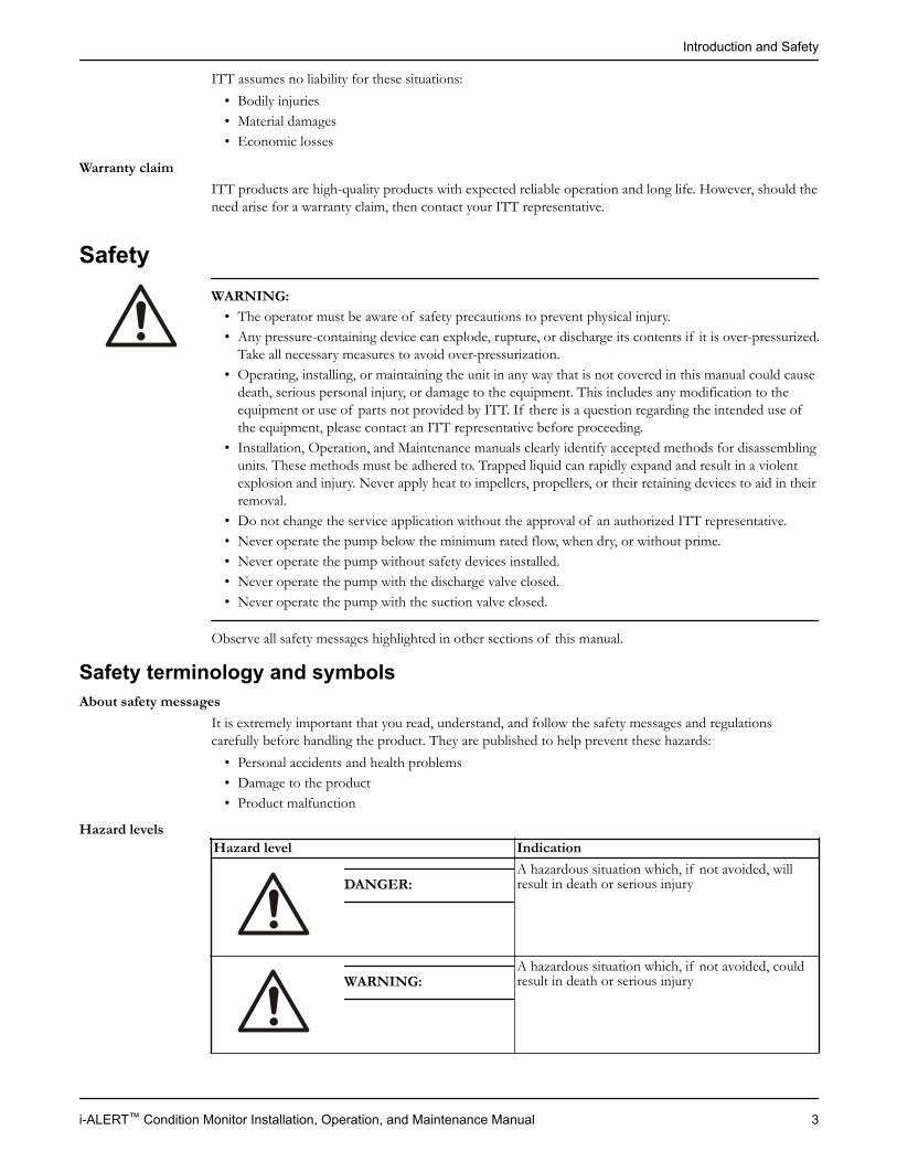
Hazard levelsHazard level Indication
DANGER: A hazardous situation which, if not avoided, willresult in death or serious injury
WARNING: A hazardous situation which, if not avoided, couldresult in death or serious injury
Introduction and Safety
i-ALERT™ Condition Monitor Installation, Operation, and Maintenance Manual 3
Hazard level Indication
CAUTION: A hazardous situation which, if not avoided, couldresult in minor or moderate injury
NOTICE: • A potential situation which, if not avoided,could result in undesirable conditions
• A practice not related to personal injury
Hazard categoriesHazard categories can either fall under hazard levels or let specific symbols replace the ordinary hazardlevel symbols.Electrical hazards are indicated by the following specific symbol:
Electrical Hazard:
These are examples of other categories that can occur. They fall under the ordinary hazard levels and mayuse complementing symbols:
• Crush hazard• Cutting hazard• Arc flash hazard
Safety regulations for Ex-approved products in potentially explosiveatmospheresDescription of ATEX
The ATEX directives are a specification enforced in Europe for electrical and non-electrical equipment.ATEX deals with the control of potentially explosive atmospheres and the standards of equipment andprotective systems used within these atmospheres. The relevance of the ATEX requirements is not limitedto Europe. You can apply these guidelines to equipment installed in any potentially explosive atmosphere.
General guidelinesATEX compliance is only fulfilled when the pump is operated within its intended use, for example withinits intended hydraulic range. The conditions of the service must not be changed without approval of anauthorized ITT representative. When installing or maintaining ATEX-compliant pumps, follow theseguidelines:
• Always install ATEX-approved equipment in compliance with the directive and applicable standards(IEC/EN 60079–14).
• Do not install FM-approved products in locations that are classified as hazardous in the nationalelectric code, ANSI/NFPA 70–2005.
WARNING:Installation, Operation, and Maintenance manuals clearly identify accepted methods for disassemblingunits. These methods must be adhered to. Trapped liquid can rapidly expand and result in a violentexplosion and injury. Never apply heat to impellers, propellers, or their retaining devices to aid in theirremoval.
If there are any questions regarding these requirements, the intended use, or if the equipment requiresmodification, contact an ITT representative before you proceed.
Personnel requirementsITT disclaims all responsibility for work done by untrained and unauthorized personnel.
Introduction and Safety
4 i-ALERT™ Condition Monitor Installation, Operation, and Maintenance Manual
These are the personnel requirements for Ex-approved products in potentially explosive atmospheres:• All work on the product must be carried out by certified electricians and ITT-authorized mechanics.
Special rules apply to installations in explosive atmospheres.• All users must know about the risks of electric current and the chemical and physical characteristics of
the gas and/or vapor present in hazardous areas.• The maintenance operation for Ex-approved products must be made in conformity to the
international or national standards (IEC/EN 60079-17).
Product and product handling requirementsThese are the product and product handling requirements for Ex-approved products in potentiallyexplosive atmospheres:
• Only use the product in accordance with the approved motor data stated on the nameplates.• The Ex-approved product must never run dry during normal operation. Dry running during service
and inspection is only permitted outside the classified area.• Never start a pump without the proper priming.• Before you start working with the product, make sure that the product and the control panel are
isolated from the power supply and the control circuit, so they cannot be energized.• Do not open the product while it is energized or in an explosive gas atmosphere.• Make sure that thermal contacts are connected to a protection circuit according to the approval
classification of the product.• Intrinsically safe circuits are normally required for the automatic level-control system by the level
regulator if mounted in zone 0.• The yield stress of fasteners must be in accordance with the approval drawing and the product
specification.• Make sure that the equipment is properly maintained:
• Monitor the pump components and the end temperature of the liquid.• Maintain proper bearing lubrication.
• Do not modify the equipment without approval from an authorized ITT representative.• Only use parts that have been provided by an authorized ITT representative.
Equipment for monitoringFor additional safety, use condition-monitoring devices. Condition-monitoring devices include but are notlimited to these devices:
• Pressure gauges• Flow meters• Level indicators• Motor load readings• Temperature detectors• Bearing monitors• Leak detectors• PumpSmart control system
Product approval standardsRegular standards
All standard products are approved according to CSA standards in Canada and UL standards in USA. Thedrive unit degree of protection follows IP68. See the nameplate for maximum submersion, according tostandard IEC 60529.All electrical ratings and performance of the motors comply with IEC 600341.
Introduction and Safety
i-ALERT™ Condition Monitor Installation, Operation, and Maintenance Manual 5
Explosion-proofing standardsAll explosion-proof products for use in explosive atmospheres are designed in compliance with one ormore of the following approvals:
• EN, ATEX Directive 94/9/EC• FM According to NEC
• Class 1 Div 1 Groups “C”, and “D”• Class 2 Div 1 Groups “E”, “F”, and “G”• Class 3 Div 1 Hazardous Locations
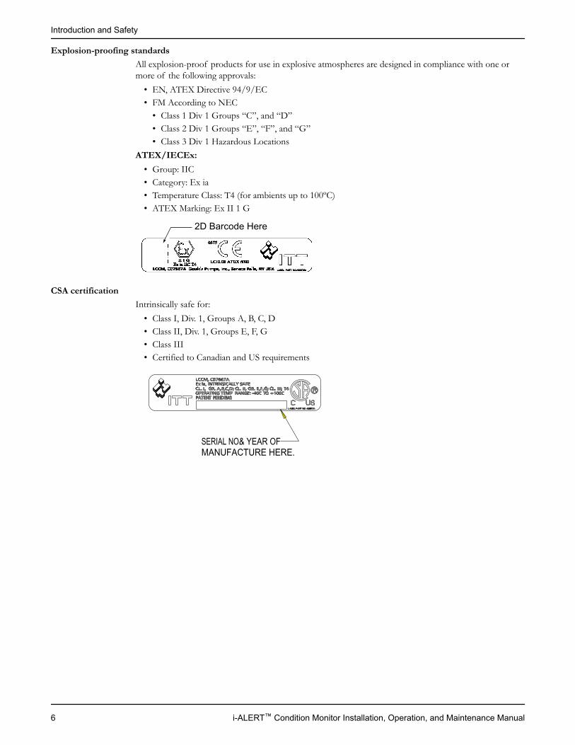
ATEX/IECEx:• Group: IIC• Category: Ex ia• Temperature Class: T4 (for ambients up to 100ºC)• ATEX Marking: Ex II 1 G
2D Barcode Here
CSA certificationIntrinsically safe for:
• Class I, Div. 1, Groups A, B, C, D• Class II, Div. 1, Groups E, F, G• Class III• Certified to Canadian and US requirements
SERIAL NO. & YEAR OFMANUFACTURE HERE.
Introduction and Safety
6 i-ALERT™ Condition Monitor Installation, Operation, and Maintenance Manual
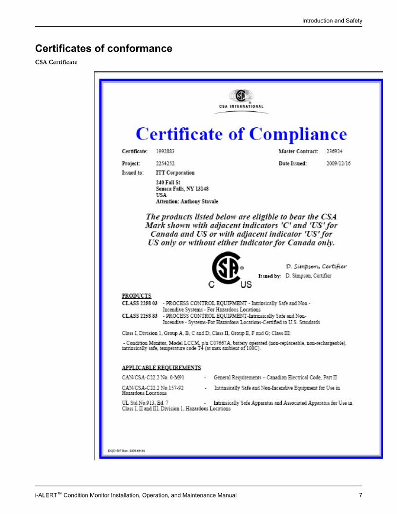
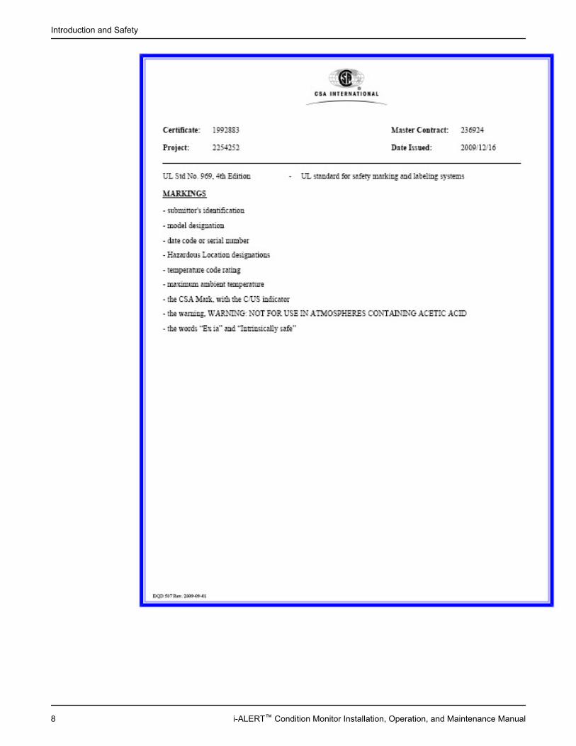
Certificates of conformanceCSA Certificate
Introduction and Safety
i-ALERT™ Condition Monitor Installation, Operation, and Maintenance Manual 7
Introduction and Safety
8 i-ALERT™ Condition Monitor Installation, Operation, and Maintenance Manual
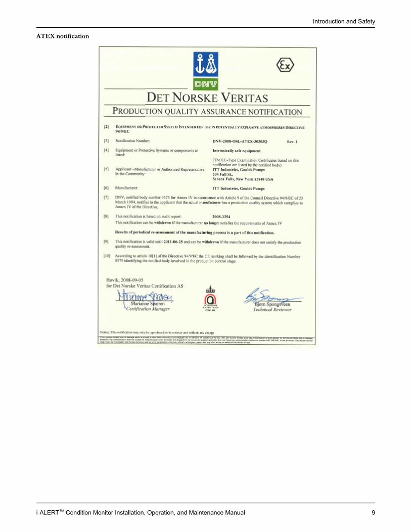
ATEX notification
Introduction and Safety
i-ALERT™ Condition Monitor Installation, Operation, and Maintenance Manual 9
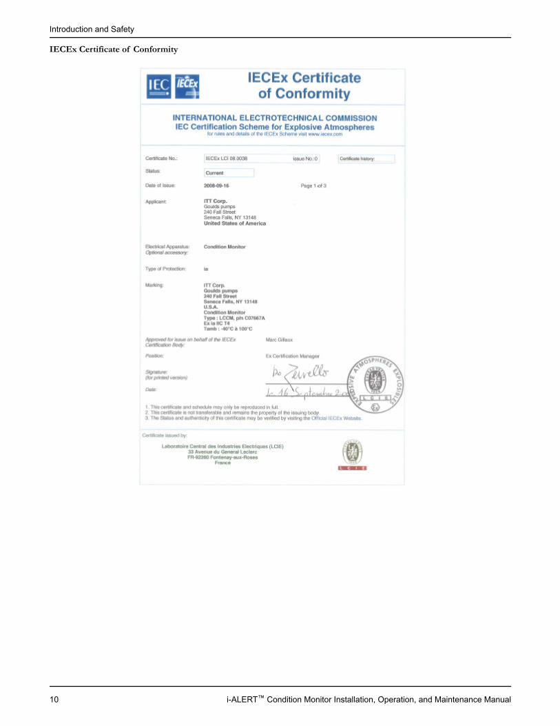
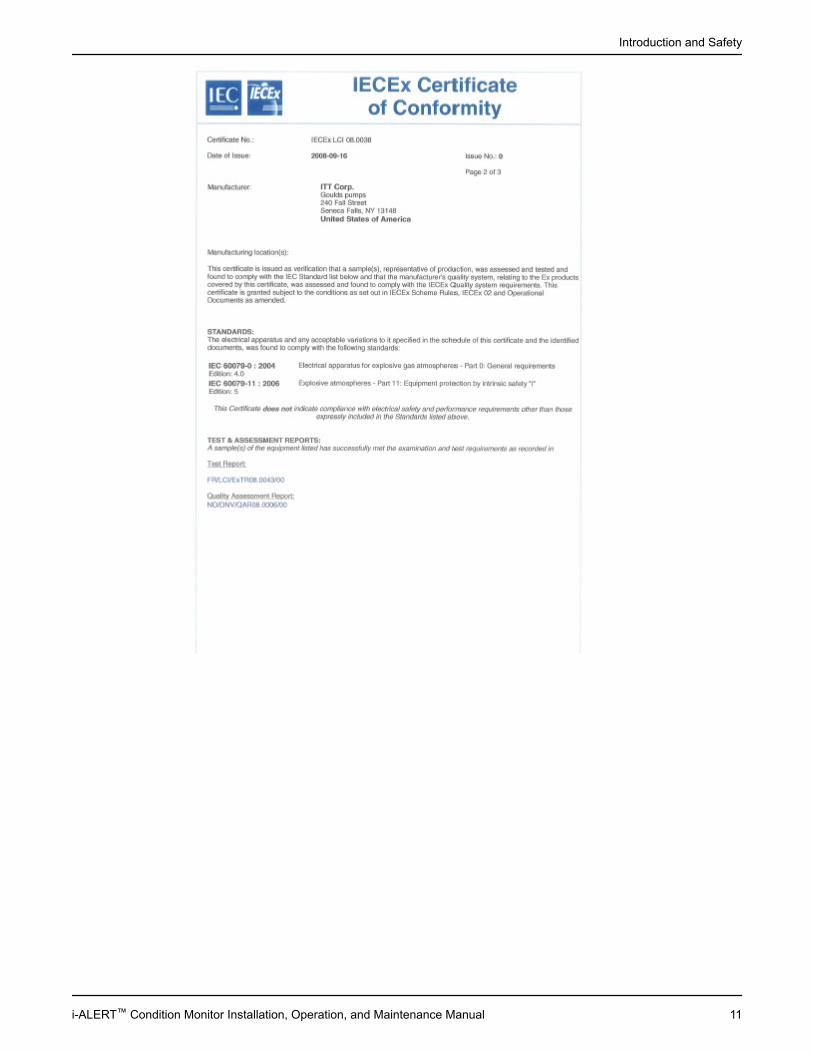
IECEx Certificate of Conformity
Introduction and Safety
10 i-ALERT™ Condition Monitor Installation, Operation, and Maintenance Manual
Introduction and Safety
i-ALERT™ Condition Monitor Installation, Operation, and Maintenance Manual 11
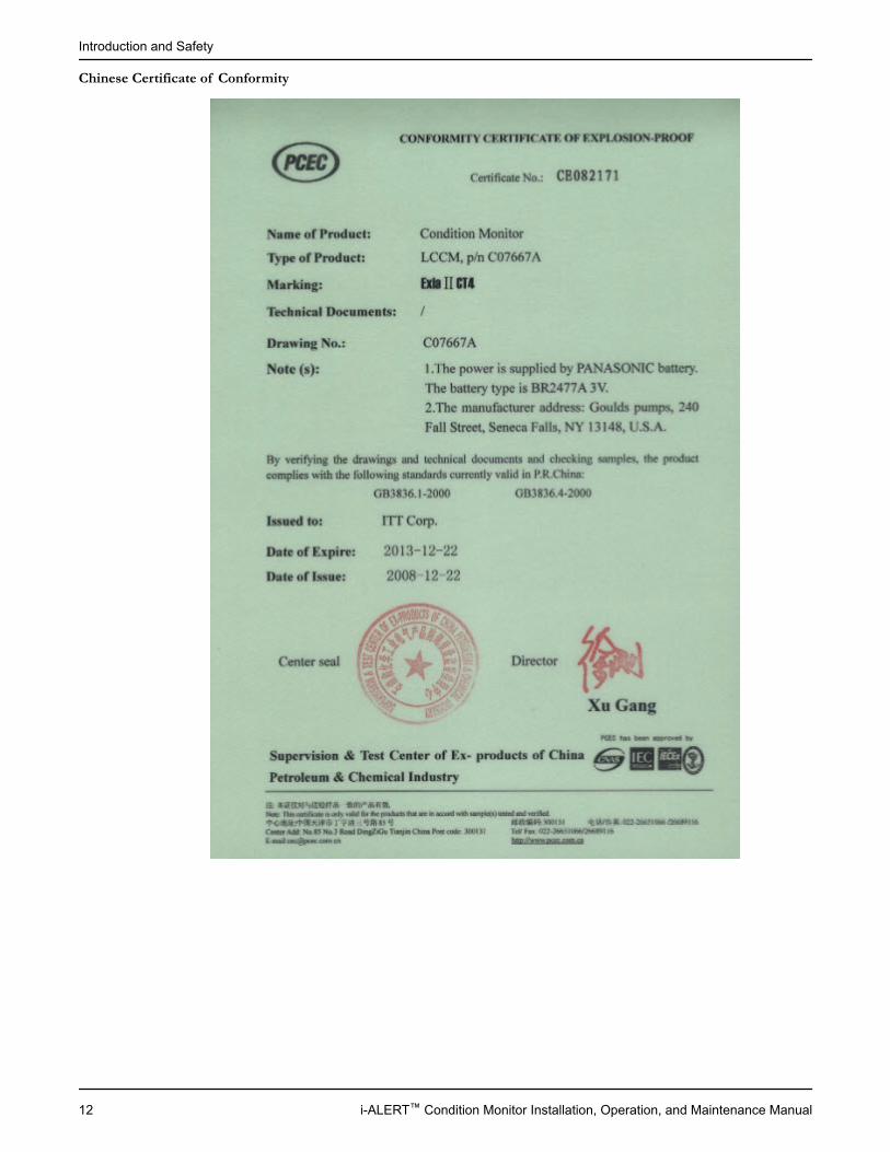
Chinese Certificate of Conformity
Introduction and Safety
12 i-ALERT™ Condition Monitor Installation, Operation, and Maintenance Manual
Product DescriptionGeneral description i-ALERT™ Condition MonitorDescription
The i-ALERT Condition Monitor is a compact, battery-operated monitoring device that continuouslymeasures the vibration and temperature of the pump power end. The condition monitor uses blinking redLEDs to alert the pump operator when the pump exceeds pre-set vibration and temperature limits. Thisallows the pump operator to make changes to the process or the pump before a catastrophic failureoccurs. The condition monitor is also equipped with a single green LED to indicate when it is operationaland has sufficient battery life.
Alarm modeThe condition monitor enters alarm mode when either vibration or temperature limits are exceeded overtwo consecutive readings within a ten minute period. Alarm mode is indicated with two red flashing LEDswithin two second intervals.
Temperature and vibration limitsVariable LimitTemperature 195°F (91°C)Vibration 100% increase over the baseline level
Battery lifeThe i-ALERT Condition Monitor battery is not replaceable. You must replace the entire unit oncethe battery runs out of power.The battery life is not covered as part of the standard five-year pump warranty.This table shows the average condition monitor battery life under normal and alarm-mode operatingconditions.Condition monitor operational state Battery lifeNormal operating and environmental conditions Three to five yearsAlarm mode One year
Product Description
i-ALERT™ Condition Monitor Installation, Operation, and Maintenance Manual 13
InstallationAttach the i-ALERT™ Condition Monitor to the pump
CAUTION:Always wear protective gloves. The pump and condition monitor can be hot.
Tools required:• 5/32 inch hex wrench
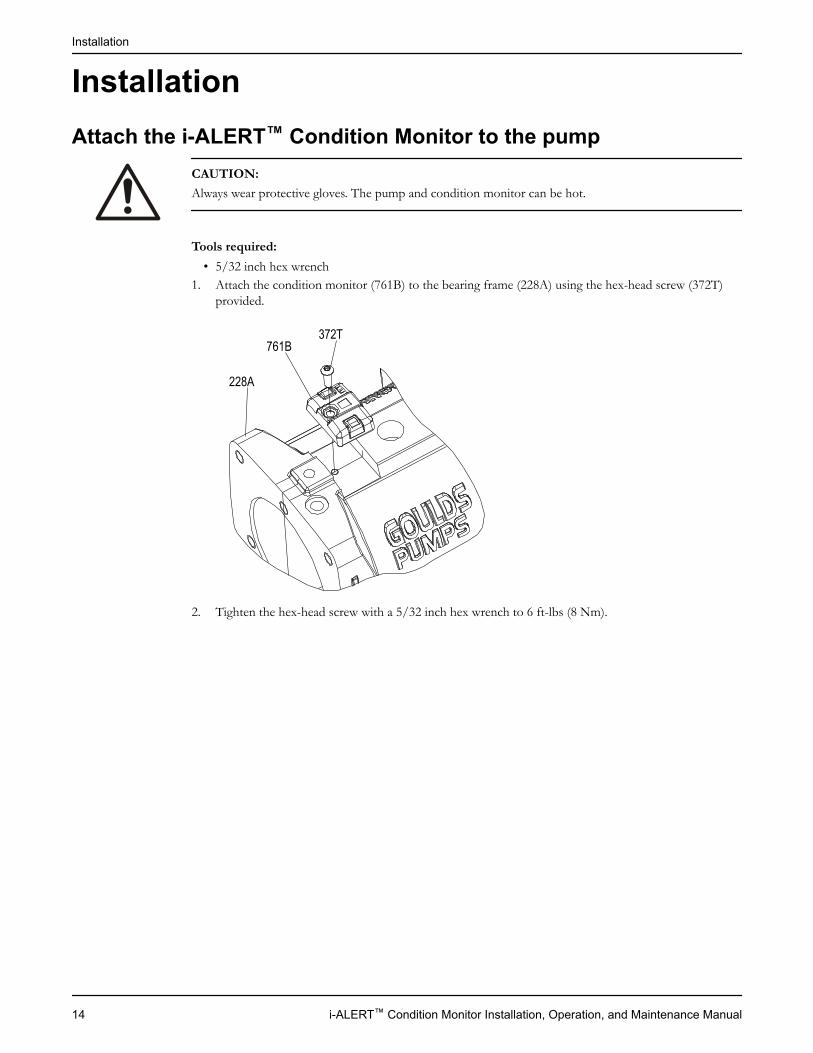
1. Attach the condition monitor (761B) to the bearing frame (228A) using the hex-head screw (372T)provided.
372T
228A
761B
2. Tighten the hex-head screw with a 5/32 inch hex wrench to 6 ft-lbs (8 Nm).
Installation
14 i-ALERT™ Condition Monitor Installation, Operation, and Maintenance Manual
Commissioning, Startup, Operation, andShutdownActivate the i-ALERT™ Condition Monitor
WARNING:Never heat the condition monitor to temperatures in excess of 300°F (149°C). Heating to thesetemperatures could result in death or serious injury.
CAUTION:Always wear protective gloves. The pump and condition monitor can be hot.
NOTICE:Do not use the condition monitor in atmospheres containing acetic acid.
The condition monitor is ready for activation when the pump is running and has reached a steady flow,pressure, and temperature. This process only takes a few minutes.
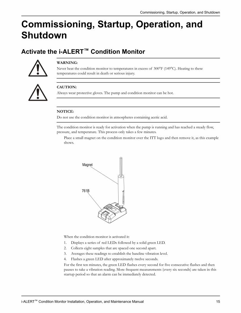
Place a small magnet on the condition monitor over the ITT logo and then remove it, as this exampleshows.
Magnet
761B
When the condition monitor is activated it:1. Displays a series of red LEDs followed by a solid green LED.2. Collects eight samples that are spaced one second apart.3. Averages these readings to establish the baseline vibration level.4. Flashes a green LED after approximately twelve seconds.For the first ten minutes, the green LED flashes every second for five consecutive flashes and thenpauses to take a vibration reading. More frequent measurements (every six seconds) are taken in thisstartup period so that an alarm can be immediately detected.
Commissioning, Startup, Operation, and Shutdown
i-ALERT™ Condition Monitor Installation, Operation, and Maintenance Manual 15
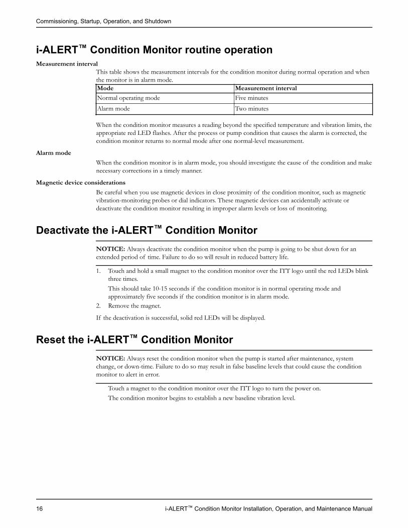
i-ALERT™ Condition Monitor routine operationMeasurement interval
This table shows the measurement intervals for the condition monitor during normal operation and whenthe monitor is in alarm mode.Mode Measurement intervalNormal operating mode Five minutesAlarm mode Two minutes
When the condition monitor measures a reading beyond the specified temperature and vibration limits, theappropriate red LED flashes. After the process or pump condition that causes the alarm is corrected, thecondition monitor returns to normal mode after one normal-level measurement.
Alarm modeWhen the condition monitor is in alarm mode, you should investigate the cause of the condition and makenecessary corrections in a timely manner.
Magnetic device considerationsBe careful when you use magnetic devices in close proximity of the condition monitor, such as magneticvibration-monitoring probes or dial indicators. These magnetic devices can accidentally activate ordeactivate the condition monitor resulting in improper alarm levels or loss of monitoring.
Deactivate the i-ALERT™ Condition MonitorNOTICE: Always deactivate the condition monitor when the pump is going to be shut down for anextended period of time. Failure to do so will result in reduced battery life.
1. Touch and hold a small magnet to the condition monitor over the ITT logo until the red LEDs blinkthree times.This should take 10-15 seconds if the condition monitor is in normal operating mode andapproximately five seconds if the condition monitor is in alarm mode.
2. Remove the magnet.
If the deactivation is successful, solid red LEDs will be displayed.
Reset the i-ALERT™ Condition MonitorNOTICE: Always reset the condition monitor when the pump is started after maintenance, systemchange, or down-time. Failure to do so may result in false baseline levels that could cause the conditionmonitor to alert in error.
Touch a magnet to the condition monitor over the ITT logo to turn the power on.The condition monitor begins to establish a new baseline vibration level.
Commissioning, Startup, Operation, and Shutdown
16 i-ALERT™ Condition Monitor Installation, Operation, and Maintenance Manual
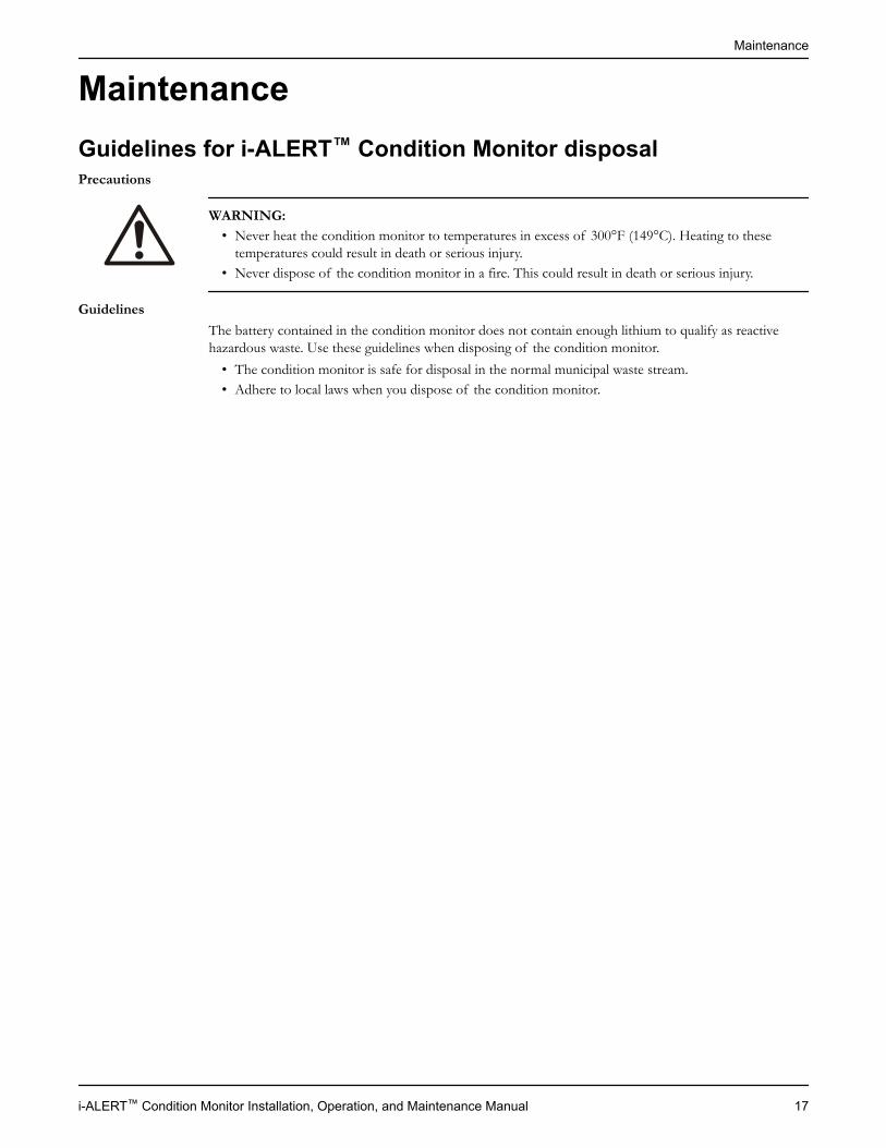
MaintenanceGuidelines for i-ALERT™ Condition Monitor disposalPrecautions
WARNING:• Never heat the condition monitor to temperatures in excess of 300°F (149°C). Heating to these
temperatures could result in death or serious injury.• Never dispose of the condition monitor in a fire. This could result in death or serious injury.
GuidelinesThe battery contained in the condition monitor does not contain enough lithium to qualify as reactivehazardous waste. Use these guidelines when disposing of the condition monitor.
• The condition monitor is safe for disposal in the normal municipal waste stream.• Adhere to local laws when you dispose of the condition monitor.
Maintenance
i-ALERT™ Condition Monitor Installation, Operation, and Maintenance Manual 17
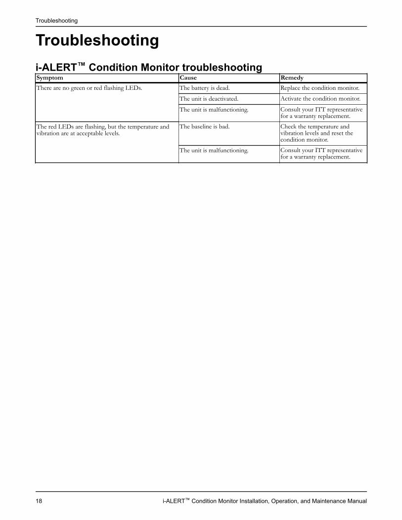
Troubleshootingi-ALERT™ Condition Monitor troubleshootingSymptom Cause RemedyThere are no green or red flashing LEDs. The battery is dead. Replace the condition monitor.
The unit is deactivated. Activate the condition monitor.
The unit is malfunctioning. Consult your ITT representativefor a warranty replacement.
The red LEDs are flashing, but the temperature andvibration are at acceptable levels.
The baseline is bad. Check the temperature andvibration levels and reset thecondition monitor.
The unit is malfunctioning. Consult your ITT representativefor a warranty replacement.
Troubleshooting
18 i-ALERT™ Condition Monitor Installation, Operation, and Maintenance Manual
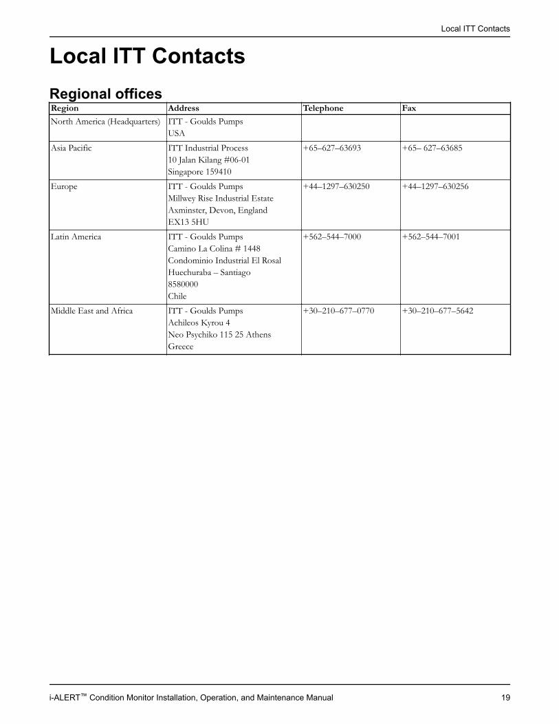
Local ITT ContactsRegional officesRegion Address Telephone FaxNorth America (Headquarters) ITT - Goulds Pumps
USAAsia Pacific ITT Industrial Process
10 Jalan Kilang #06-01Singapore 159410
+65–627–63693 +65– 627–63685
Europe ITT - Goulds PumpsMillwey Rise Industrial EstateAxminster, Devon, EnglandEX13 5HU
+44–1297–630250 +44–1297–630256
Latin America ITT - Goulds PumpsCamino La Colina # 1448Condominio Industrial El RosalHuechuraba – Santiago8580000Chile
+562–544–7000 +562–544–7001
Middle East and Africa ITT - Goulds PumpsAchileos Kyrou 4Neo Psychiko 115 25 AthensGreece
+30–210–677–0770 +30–210–677–5642
Local ITT Contacts
i-ALERT™ Condition Monitor Installation, Operation, and Maintenance Manual 19


How did we measure up?
It is our sincere intention to exceed our customer’s expectations on every order. Tellus if we achieved our goal on your order. Please take our customer satisfactionsurvey online at:www.ittindustrialproducts.com/feedbacksurvey.htmlWe appreciate you taking the time to provide your feedback. Thank you for buyingITT pumps, parts, and controls.
Contact Us
Goulds Pumps has offices, warehouses and manufacturing facilities worldwide,while doing business in over 100 countries in the Americas, Europe, the Middle Eastand Asia Pacific. To find your nearest distributor, use our convenient Sales andService Locator found on our Web site.
Visit our Web site for the latest version of this document and more information
Goulds Pumps
© 2010 ITT Corporation. The original instruction is in English. All non-English instructions are translations of the originalinstruction. en-US.2010-04.IOM.i-ALERT™ConditionMonitor