Embed Size (px)
Citation preview
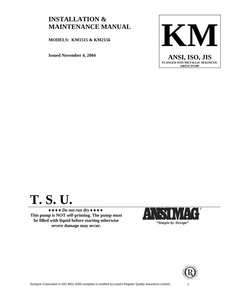
Sundyne Corporation is ISO 9001-2000 compliant is certified by Lloyd’s Register Quality Assurance Limited. 1
INSTALLATION & MAINTENANCE MANUAL MODELS: KM1515 & KM2156 Issued November 4, 2004
KMANSI, ISO, JIS
FLANGED NON-METALLIC MAGNETIC DRIVE PUMP
T. S. U. ♦♦♦♦Do not run dry ♦♦♦♦
This pump is NOT self-priming. The pump must be filled with liquid before starting otherwise
severe damage may occur.
“Simple by Design”
2
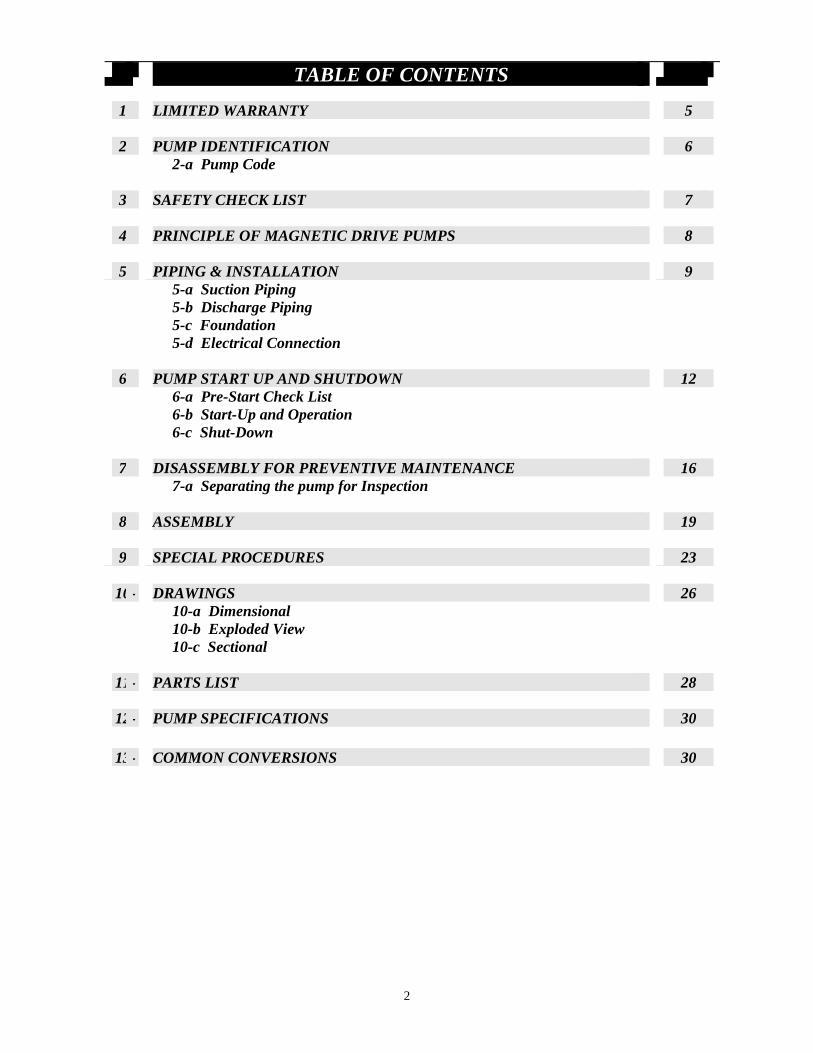
TABLE OF CONTENTS
1- LIMITED WARRANTY 5
2- PUMP IDENTIFICATION 6 2-a Pump Code
3- SAFETY CHECK LIST 7
4- PRINCIPLE OF MAGNETIC DRIVE PUMPS 8
5- PIPING & INSTALLATION 9 5-a Suction Piping 5-b Discharge Piping 5-c Foundation 5-d Electrical Connection
6- PUMP START UP AND SHUTDOWN 12 6-a Pre-Start Check List 6-b Start-Up and Operation 6-c Shut-Down
7- DISASSEMBLY FOR PREVENTIVE MAINTENANCE 16 7-a Separating the pump for Inspection
8- ASSEMBLY 19
9- SPECIAL PROCEDURES 23
10- DRAWINGS 26 10-a Dimensional 10-b Exploded View 10-c Sectional
11- PARTS LIST 28
12- PUMP SPECIFICATIONS 30
13- COMMON CONVERSIONS 30
3
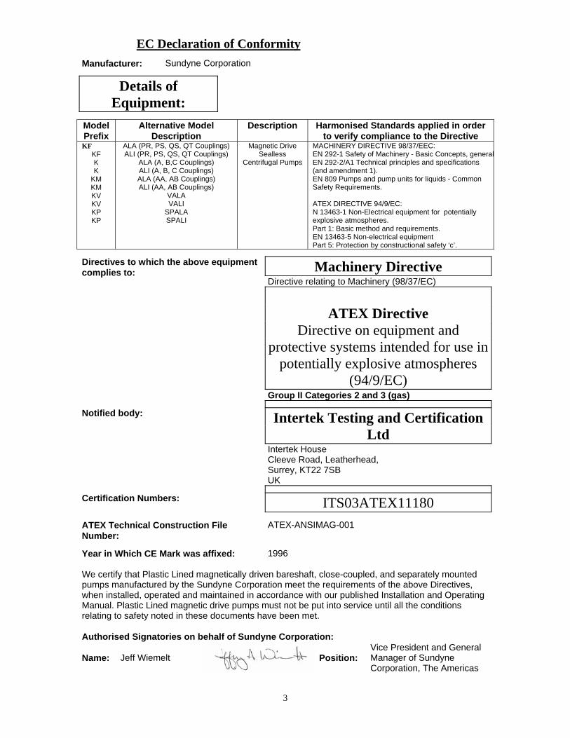
EC Declaration of ConformityEC Declaration of Conformity
Manufacturer: Sundyne Corporation
Details of Equipment:
Model Prefix
Alternative Model Description
Description Harmonised Standards applied in order to verify compliance to the Directive
KF KF K K
KM KM KV KV KP KP
ALA (PR, PS, QS, QT Couplings) ALI (PR, PS, QS, QT Couplings)
ALA (A, B,C Couplings) ALI (A, B, C Couplings) ALA (AA, AB Couplings) ALI (AA, AB Couplings)
VALA VALI
SPALA SPALI
Magnetic Drive Sealless
Centrifugal Pumps
MACHINERY DIRECTIVE 98/37/EEC: EN 292-1 Safety of Machinery - Basic Concepts, generalEN 292-2/A1 Technical principles and specifications (and amendment 1). EN 809 Pumps and pump units for liquids - Common Safety Requirements. ATEX DIRECTIVE 94/9/EC: N 13463-1 Non-Electrical equipment for potentially explosive atmospheres. Part 1: Basic method and requirements. EN 13463-5 Non-electrical equipment Part 5: Protection by constructional safety ‘c’.
Directives to which the above equipment complies to: Machinery Directive
Directive relating to Machinery (98/37/EC)
ATEX Directive
Directive on equipment and protective systems intended for use in
potentially explosive atmospheres (94/9/EC)
Group II Categories 2 and 3 (gas)
Notified body: Intertek Testing and Certification Ltd
Intertek House Cleeve Road, Leatherhead, Surrey, KT22 7SB UK
Certification Numbers: ITS03ATEX11180 ATEX Technical Construction File Number:
ATEX-ANSIMAG-001
Year in Which CE Mark was affixed: 1996 We certify that Plastic Lined magnetically driven bareshaft, close-coupled, and separately mounted pumps manufactured by the Sundyne Corporation meet the requirements of the above Directives, when installed, operated and maintained in accordance with our published Installation and Operating Manual. Plastic Lined magnetic drive pumps must not be put into service until all the conditions relating to safety noted in these documents have been met. Authorised Signatories on behalf of Sundyne Corporation:
Name: Jeff Wiemelt Position: Vice President and General Manager of Sundyne Corporation, The Americas
4
Name: Kerry Kramlich
Position: Pump Engineering Manager
Date of issue: 16th June 2003 Place of Issue: United Kingdom
SAFETY WARNINGGenuine parts and accessories have been specifically designed and tested for use with these products toensure continued product quality and performance. Testing cannot be performed on all parts nor onaccessories sourced from other vendors, incorrect design and/or fabrication of such parts and accessoriesmay adversely affect the performance and safety features of these products. Failure to properly select,install or use authorised Sundyne parts and accessories is considered misuse, and damage or failurecaused by misuse is not covered by Sundyne’s warranty. Additionally, modification of Sundyne products orremoval of original components may impair the safety of these products and their effective operation.
EUROPEAN UNION MACHINERY DIRECTIVE(CE mark system)
This document incorporates information relevant to the Machinery Directive 98/37/EC. It should be read priorto the use of any of our equipment. Individual maintenance manuals which also conform to the EU Directiveshould be read when dealing with specific models.
EUROPEAN UNION ATEX DIRECTIVE
This document incorporates information relevant to the ATEX Directive 94/9/EC (Directive on equipment andprotective systems intended for use in potentially explosive atmospheres). It should be read prior to the useof any of our equipment.
Compliance to the Directive is based on Atmospheres having pressures up to but not exceeding 350psi andtemperatures ranging from –120 °F to + 250 °F depending on the model.
As indicated in the ATEX Directive 94/9/EC, it is the responsibility of the user of the pump to indicate toSundyne Corporation the Zone and Corresponding group (Dust or Gas) that the pump is to be installedwithin. Should the pump be put into service in a potentially explosive atmosphere, the user of the pumpmust put the grounding connector into use.

5
1. Limited Warranty One year limited warranty Ansimag pumps are warranted by Ansimag to the original user against defects in workmanship and materials under normal use for one year after the date of purchase. Any part returned to an Ansimag- designated, authorized service location, shipping cost prepaid, will be evaluated for defects. Parts determined by Ansimag to be defective in material or workmanship will be repaired or replaced at Ansimag's option as the exclusive remedy. Limitation of liability To the extent allowable under applicable law, Ansimag's liability for consequential damages is expressly disclaimed. Ansimag's liability in all events is limited to and shall not exceed the purchase price paid. Warranty disclaimer Ansimag has made a diligent effort to illustrate and describe the products in this literature accurately; however, such illustrations and descriptions are for the sole purpose of identification and do not express or imply a warranty that the products are merchantable, or fit for a particular purpose, or that the products will necessarily conform to the illustration or descriptions. Except as provided below, no warranty or affirmation of fact, expressed or implied, other than as stated in "LIMITED WARRANTY" is made or authorized by Ansimag. Product suitability Many states and localities have codes and regulations governing the sale, construction, installation and/or use of products for certain purposes, which may vary from those in neighboring areas. While Ansimag attempts to assure that its products comply with such codes, it cannot guarantee compliance, and cannot be responsible for how the product is installed or used. Before purchasing and using a product, please review the product application as well as the national and local codes and regulations, and be sure that product, installation, and use complies with them. Warranty exclusions Wear items that must be replaced on a regular basis are not covered under this warranty. Such items include, but are not limited to mouth rings/pads, thrust rings, O-rings, bushings and shafts. Items that have been subject to extreme heat or have been used with abrasive or incompatible chemicals are not covered under this warranty.
6
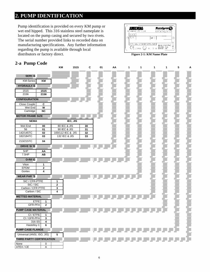
2. PUMP IDENTIFICATION
Figure 2-1: KM Name Plate
2-a Pump Code KM 1515 C 01 AA 1 1 1 1 5 A
SERIES
KM-Series KM
HYDRAULICS
1515 1515 2156 2156
CONFIGURATION
Close Couple C Wet End W Cartridge NC
MOTOR FRAME SIZE
NEMA IEC, JIS
Wet End 00 80 IEC & JIS 30 56 01 90 IEC & JIS 31
142/145TC 02 100/112 IEC & JIS 32 182/184TC 03 132 IEC & JIS 33
213/215TC 04
DRIVE SIZE
5HP AA 7.5HP AB
O-RING
Viton 1 EPDM 2 Gortex 4
WEAR PARTS
SIC / CFR-PTFE 1 SIC / SIC 2
Carbon / CFR PTFE 3 Carbon / SIC 4
WETTED MATERIAL
ETFE 1 GFR-PFA 2
PUMP CASE MATERIAL
CI / ETFE 1 CI / GFR-PFA 3
316 SS 4 Hastelloy C 6
PUMP CASE FLANGE
Universal (ANSI, ISO, JIS) 5
THIRD PARTY CERTIFICATION
None 0 ATEX / CE A
Pump identification is provided on every KM pump or wet end hipped. This 316 stainless steel nameplate is located on the pump casing and secured by two rivets. The serial number provided links to recorded data on manufacturing specifications. Any further information regarding the pump is available through local distributors or factory direct.

7
3. SAFETY CHECKLIST The following checklist presents some common precautions to remember when working with magnetic drive pumps.
Warning! Magnetic Field Hazard. Magnetic drive pumps contain some of the world's strongest magnets. These magnets are located in the impeller and outer drive magnet assemblies. The powerful magnetic fields could adversely affect persons who are assisted by electronic devices. Pacemakers and defibrillators are examples of these devices.
Warning! Hot Surfaces Hazard. These pumps are designed to handle liquids at temperatures up to 250oF and will become hot on the outside. This creates a hazard of burns to personnel coming in contact with the equipment.
Warning! Magnetic Forces Hazard. Use only the recommended disassembly and assembly procedures when separating the wet end from the drive end.
Warning! Rotating Parts Hazard. The pump contains parts, which rotate during operation. Before operation the pump must have the coupling guard secured in place and be completely assembled. To prevent injury during maintenance the pump and/or driver must be disconnected from the power source. Local safety standards apply.
Warning! Chemical Hazard. The pumps are designed to handle all types of chemical solutions. Many are hazardous to personnel. This hazard could take the form of leaks and spills during maintenance. Plant procedures for decontamination should be followed during pump disassembly and part inspection. There is always the possibility of small quantities of liquid being trapped between pump components
Caution! Magnetic Field Sensitive Items. Do not put magnetic field sensitive items such as credit cards, floppy diskettes or magnetic tapes near the impeller or drive magnet assemblies.
Caution! Metal Tools. Do not use steel or iron tools near magnets. Steel tools such as wrenches and screwdrivers are easily attracted to magnets and can break them on contact.
8
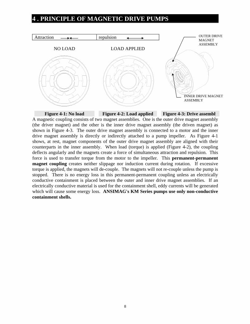
4 . PRINCIPLE OF MAGNETIC DRIVE PUMPS
Attraction repulsion
NO LOAD
LOAD APPLIED
Figure 4-1: No load Figure 4-2: Load applied Figure 4-3: Drive assembly A magnetic coupling consists of two magnet assemblies. One is the outer drive magnet assembly (the driver magnet) and the other is the inner drive magnet assembly (the driven magnet) as shown in Figure 4-3. The outer drive magnet assembly is connected to a motor and the inner drive magnet assembly is directly or indirectly attached to a pump impeller. As Figure 4-1 shows, at rest, magnet components of the outer drive magnet assembly are aligned with their counterparts in the inner assembly. When load (torque) is applied (Figure 4-2), the coupling deflects angularly and the magnets create a force of simultaneous attraction and repulsion. This force is used to transfer torque from the motor to the impeller. This permanent-permanent magnet coupling creates neither slippage nor induction current during rotation. If excessive torque is applied, the magnets will de-couple. The magnets will not re-couple unless the pump is stopped. There is no energy loss in this permanent-permanent coupling unless an electrically conductive containment is placed between the outer and inner drive magnet assemblies. If an electrically conductive material is used for the containment shell, eddy currents will be generated which will cause some energy loss. ANSIMAG's KM Series pumps use only non-conductive containment shells.
OUTER DRIVE MAGNET ASSEMBLY
INNER DRIVE MAGNET ASSEMBLY
9
5. PUMP INSTALLATION 5-a. PIPING
1. Install the pump as close as possible to the suction tank. Pumps are designed to push, not pull, liquid.
2. Ansimag recommends supporting and restraining both the suction and discharge pipes near the pump to avoid the application of forces and moments to the pump casing. All piping should line up with the pump flanges naturally to minimize any bending moments at the pump nozzles.
3. To minimize friction the suction line should have a short straight run to the pump, and be free of fittings, for a length equivalent to or larger than ten (10) times its diameter.
4. The suction line size should be at least as large as the pump's suction port or one size larger
if the suction line is so long that it significantly affects NPSH available. Never reduce the suction piping size.
5. The suction line should have no high points since these can create air pockets. 6. The NPSH available to the pump must be greater than the NPSH required. Screens and
filters in the suction line will reduce the NPSH available, and must be considered in the calculations.
7. Caution: Do not install a check valve in the suction line even if a check valve is
installed in the discharge line. The suction line check valve could shut off before the discharge line check valve closes. This would cause water hammer, which may burst the containment shell.
8. The discharge piping should be equal in size to the pump outlet port. 9. A stop valve and a check valve should be installed in the discharge line. The stop valve is
used when starting and stopping the pump, and to isolate the pump for maintenance. It is advisable to close the stop valve before stopping the pump. The check valve will protect the pump from water hammer damage. These recommendations are especially important when the static discharge head is high.
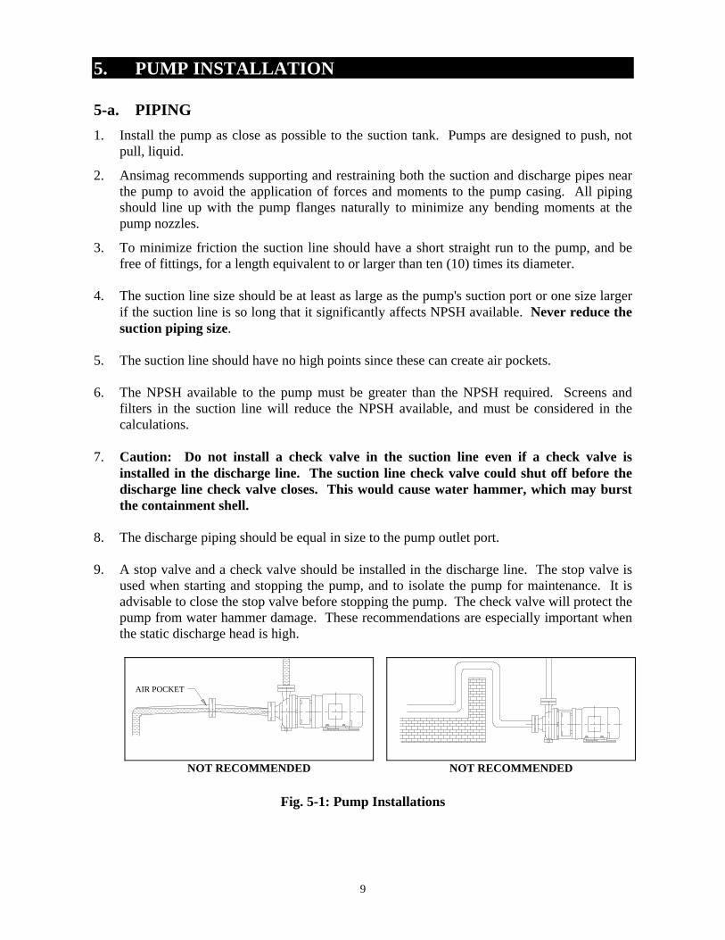
AIR POCKET
NOT RECOMMENDED NOT RECOMMENDED
Fig. 5-1: Pump Installations

10
5-b. FOUNDATION
Fig. 5-2
1. The foundation should be sufficiently substantial to absorb vibration and form a permanent,
rigid support for the base plate. This is essential for maintaining alignment of a long coupled unit. A concrete foundation should be satisfactory. Embed foundation bolts of the proper size (1/2" -13 x 7" recommended for ordinary installation) in the concrete, located by a drawing or template. Use a pipe sleeve larger than the bolt to allow enough base movement for final positioning of the bolts.
2. Support the base plate on rectangular metal blocks and shims, or on metal wedges with a
small taper. Place the support pieces close to the foundation bolts. A spacing of 24" is suggested. Allow a gap of 3/4" to 1-1/2" between the base plate and the foundation for grouting.
3. Adjust the metal supports or wedges until the shafts of the pump and driver are level. Check
the horizontal or vertical positions of the coupling faces as well as the suction and discharge flanges of the pump by means of a level. Correct the positions, if necessary, by adjusting the supports or wedges under the base plate as required.
4. When alignment is correct, tighten foundation bolts evenly but not too firmly. The units can
then be grouted to the foundation. The legs of the base plate should be completely filled with grout and the leveling pieces, shims, or wedges should be grouted in place. The foundation bolts should not be tightened until the grout is hardened, usually about 48 hours after pouring.
NEVER OPERATE THE PUMP WITHOUT FIRST SECURING IT INTO POSITION!
11
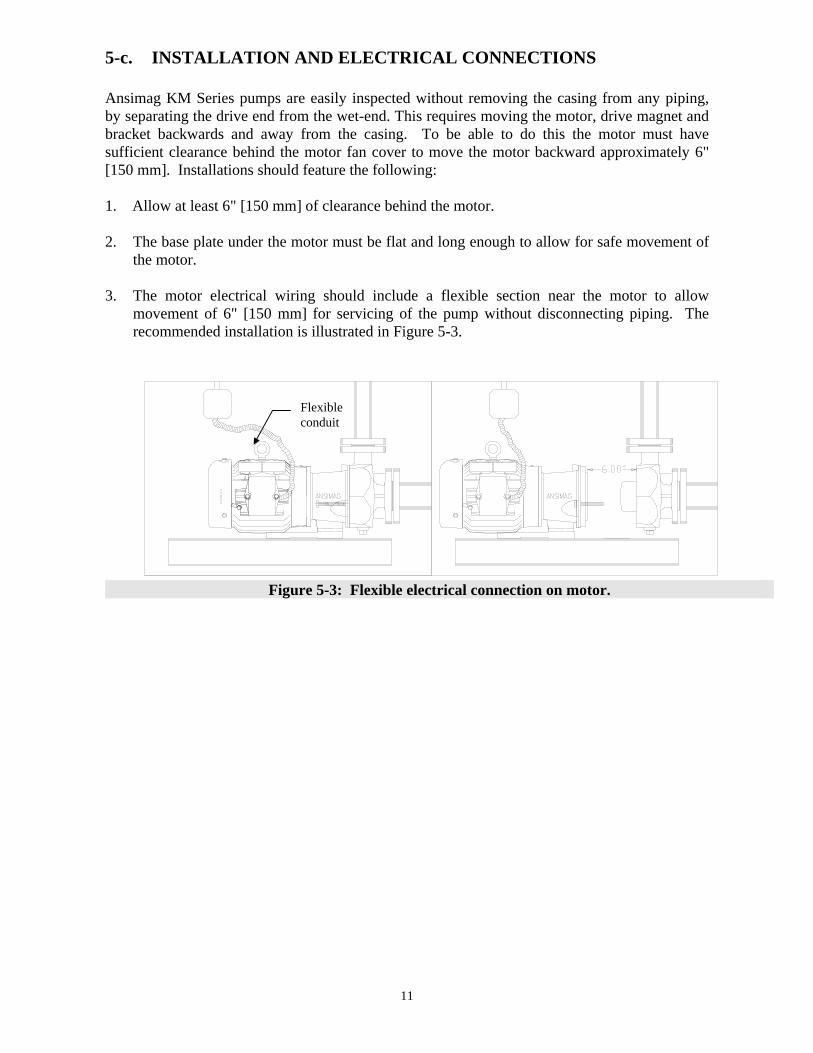
5-c. INSTALLATION AND ELECTRICAL CONNECTIONS Ansimag KM Series pumps are easily inspected without removing the casing from any piping, by separating the drive end from the wet-end. This requires moving the motor, drive magnet and bracket backwards and away from the casing. To be able to do this the motor must have sufficient clearance behind the motor fan cover to move the motor backward approximately 6" [150 mm]. Installations should feature the following: 1. Allow at least 6" [150 mm] of clearance behind the motor. 2. The base plate under the motor must be flat and long enough to allow for safe movement of
the motor. 3. The motor electrical wiring should include a flexible section near the motor to allow
movement of 6" [150 mm] for servicing of the pump without disconnecting piping. The recommended installation is illustrated in Figure 5-3.
Figure 5-3: Flexible electrical connection on motor.
Flexible conduit

12
6. PUMP START UP AND SHUTDOWN
6-a. PRE-START CHECKLIST Before initial start up and after inspections of the wet end of pump, perform the following inspections: 1. With the pump starter locked out, manually turn the motor fan or flexible coupling to insure
that it rotates freely. For a motor mounted directly to the pump (close coupled), insert a screwdriver or other tool through the fan cover and rotate the fan. It should rotate freely.
2. Check all electrical connections with a wiring diagram. Make sure that the voltage, frequency and horsepower on the motor nameplate match the line circuit.
3. Check that flange bolts are tightened and that the drain cover is in place. 6-b. START UP AND OPERATION Caution!: KM Series horizontal end suction models are not self-priming pumps! The pump
must be filled with liquid by gravity from a flooded suction tank or primed by other methods such as injecting liquid from an outside source into the pump and suction line with an attached foot valve.
1. Make sure that the pump is full of liquid and the suction valve is open.
2. Fully open the discharge valve once and then close it, so that any air trapped in the pump and suction line can be purged.
3. With the pump full of liquid, check motor rotation by jogging the pump and motor for about 1/2 second. The proper rotation is clockwise as viewed from the motor fan end. Once proper motor rotation is confirmed jog the motor 5 or 6 more times. This process is very important to fully wet sleeve bushing and pump shaft, and to purge some of the air trapped in the pump and discharge line.
4. Open the discharge valve once and close it again so that more air can be released downstream.
5. Turn the pump on. Open the discharge valve slowly. It is important to open the valve very slowly. Sudden opening of the valve while air is trapped between the pump and the valve may cause water hammer.
6. Keep the suction valve fully opened. Do not use the suction valve to adjust flow rate. Adjust the flow rate with the discharge valve only.
NOTE: Subsequent pump starts do not require motor jogging or valve position changes provided that the piping and pump have remained full of liquid.
13
Caution! Do not run the pump dry. The pump may be severely damaged. The pumps
use slide bearings that are lubricated by the pumped product. No lubrication, no bearings. Even short periods of dry running could damage the pump.
Caution! Do not Dead Head. Although the radial loads on the bearings are not a concern, the liquid in the pump will rapidly increase in temperature. This will continue until the boiling point is reached. Some liquids boil at temperatures sufficient to melt pump components and destroy the magnets. Other liquids will flash into vapor. This vapor collects at the main bushing causing dry running.
Caution! Cavitation. Prolonged cavitation may cause pitting on the pump components. Short term severe cavitation, such as that caused by a closed suction may damage the pump bearings.
Caution! Water Hammer. Sudden changes in fluid velocity can cause large, rapid pressure surges. These pressure surges can damage the pump, piping and instrumentation. Typical causes are rapidly closing valves. Check valves on the suction can also cause water hammer if the liquid has time to reverse direction before the valve closes.
Recommended! Power Monitors. We recommend installing a Sundyne power monitor on all pumps. These devices are very effective at protecting the pumps from dry running, cavitation or when frequent overload is expected. They are also very effective for stoppage during tank unloading applications.
• Dry Running • Pump Seizure • Closed Valve • Severe Cavitation • Clogged Suction Filter • Excess (High) Flow

14
Safety TEMPERATURE CLASSIFICATION - (ATEX DIRECTIVE 94/9/EC) The maximum surface temperature of a metallic magnetic drive pump is the highest temperature ascertained from any one of the following conditions: 1. The temperature of the pumped liquid, plus 20°C. or 2. The ambient temperature plus 20°C. or 3. The ambient temperature plus 39°C (only in the case of separately mounted pumps with oil lubricated bearing assemblies) or 4. The temperature of the heating medium being used in the heating jacket (if fitted) The actual classification is calculated by obtaining the maximum surface temperature and than using the following table to obtain the relevant Temperature Class:
Temperature Class Maximum Surface Temperature (°C)
T1 450 (842°F) T2 300 (572°F) T3 200 (392°F) T4 135 (275°F) T5 100 (212°F) T6 85 (185°F)
Example: The pump is pumping a liquid with a temperature of 120°C. The pump is close coupled and therefore does not have an external oil lubricated bearings. The maximum ambient temperature in which the pump may operate is 30°C Condition 1 equates to 120°C + 20°C = 140°C
Condition 2 equates to 30°C + 20°C = 50°C Condition 3 does not apply. Condition 4 does not apply.
Thus the maximum surface temperature of the pump is 140°C which equates to a temperature classification of T3.

15
6-c. SHUTDOWN If the pump is to be shut down for any reason, use the following procedure: 1. Close the discharge valve slowly to prevent water hammer. 2. Shut off the motor. 3. Close the suction valve.
16
7. DISASSEMBLY FOR PREVENTIVE MAINTENANCE WARNING! Before disassembly, the pump must have the drive “locked out” and be flushed of all dangerous liquids. Follow all federal, state, local and company regulations with regard to pump decontamination prior to disassembly and inspection. ANSIMAG KM Series pumps are provided with a low point casing drain to maximize pump decontamination. Refer to section 9 “Special Procedures” Simple features of the KM Series pump make possible a 20-minute maintenance check by following the provided instructions. Please prepare the necessary tools for pump maintenance. 7-a Tool Checklist
8mm hex key or 5/16" hex
19mm combination wrench
PT0377 - bushing installation/removal & trimming tool
PT0285 - shaft support installation tool
Arbor press
Since most wearing parts on a mag-drive pump cannot be monitored, it is important to inspect the pump for wear after the initial 500 hours or three months of operation, whichever comes first. The next inspection will be six to twelve months depending on the result of the first inspection. Before inspecting, be sure you have a spare casing O-ring on hand to re-install after the inspection is completed. To inspect inside of the pump, be sure that the pump has been flushed of all dangerous liquids before isolating the pump by closing the inlet and outlet valves. Operating conditions vary so widely that recommending one schedule of preventive maintenance for all centrifugal pumps is not possible. In the case of magnetic drive pumps, particularly of non-metallic pumps, traditional maintenance techniques, such as vibration monitoring are not useful or reliable techniques for wet end preventive maintenance. These are effective only for non-liquid contact components such as motor bearings. One of the best rules to follow in proper maintenance is to keep a record of actual operating data such as flow, pressure, motor load and hours of operation. The length of the safe operation period will vary with different applications and can only be determined from experience.
17
7-b Separating The Pump For Inspection
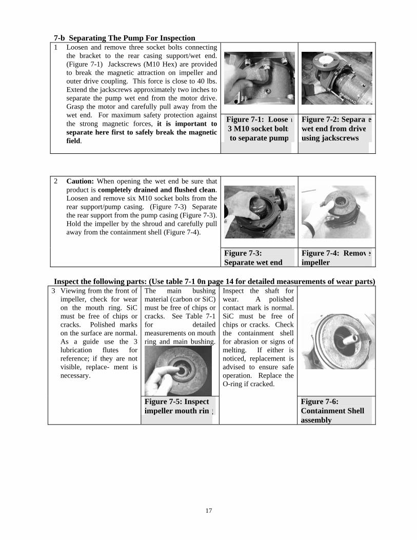
1 Loosen and remove three socket bolts connecting the bracket to the rear casing support/wet end. (Figure 7-1) Jackscrews (M10 Hex) are provided to break the magnetic attraction on impeller and outer drive coupling. This force is close to 40 lbs. Extend the jackscrews approximately two inches to separate the pump wet end from the motor drive. Grasp the motor and carefully pull away from the wet end. For maximum safety protection against the strong magnetic forces, it is important to separate here first to safely break the magnetic field.
Figure 7-1: Loosen 3 M10 socket bolts to separate pump
Figure 7-2: Separate wet end from drive using jackscrews
2 Caution: When opening the wet end be sure that product is completely drained and flushed clean. Loosen and remove six M10 socket bolts from the rear support/pump casing. (Figure 7-3) Separate the rear support from the pump casing (Figure 7-3). Hold the impeller by the shroud and carefully pull away from the containment shell (Figure 7-4).
Figure 7-3:
Separate wet end Figure 7-4: Remove impeller
Inspect the following parts: (Use table 7-1 0n page 14 for detailed measurements of wear parts)
3 Viewing from the front of impeller, check for wear on the mouth ring. SiC must be free of chips or cracks. Polished marks on the surface are normal. As a guide use the 3 lubrication flutes for reference; if they are not visible, replace- ment is necessary.
The main bushing material (carbon or SiC) must be free of chips or cracks. See Table 7-1 for detailed measurements on mouth ring and main bushing.
Inspect the shaft for wear. A polished contact mark is normal. SiC must be free of chips or cracks. Check the containment shell for abrasion or signs of melting. If either is noticed, replacement is advised to ensure safe operation. Replace the O-ring if cracked.
Figure 7-5: Inspect impeller mouth ring
Figure 7-6: Containment Shell assembly
18
4 Check the outside of
the containment shell for abrasive marks or cracks. Replace if necessary.
A 304 Stainless Steel cover protects the outer drive magnets. Check for any particles and clean if necessary.
Figure 7-7: Inspect Containment Shell
Figure 7-8: Inspect outer drive magnet assembly
5 Casing lining must be
free of cracks. Check the integrity of lining by using 15-20 KV electrostatic discharge tester commonly used for lined pipe.
Inspect SiC thrust ring for cracks or chips.
Figure 7-9: Inspect casing lining
Figure 7-10: Inspect thrust ring
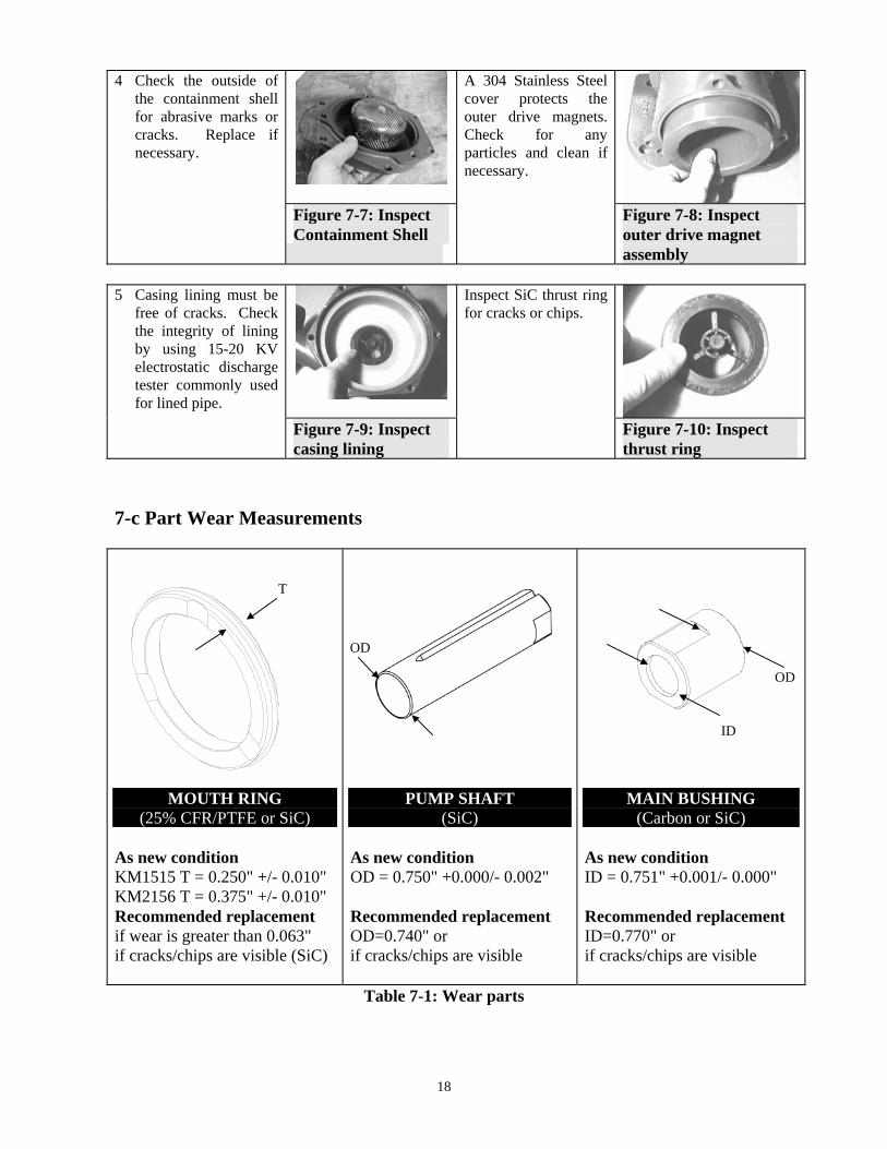
7-c Part Wear Measurements
MOUTH RING (25% CFR/PTFE or SiC)
As new condition KM1515 T = 0.250" +/- 0.010" KM2156 T = 0.375" +/- 0.010" Recommended replacement if wear is greater than 0.063" if cracks/chips are visible (SiC)
PUMP SHAFT (SiC)
As new condition OD = 0.750" +0.000/- 0.002" Recommended replacement OD=0.740" or if cracks/chips are visible
MAIN BUSHING (Carbon or SiC)
As new condition ID = 0.751" +0.001/- 0.000" Recommended replacement ID=0.770" or if cracks/chips are visible
Table 7-1: Wear parts
T
OD
ID
OD

19
8. ASSEMBLY 1 Prepare a clean surface for assembly on the shop
workbench. An upright or vertical assembly of the KM is preferred; however, horizontal assembly methods work well too. Place the motor on the clean surface vertically with the motor shaft pointing up. Place the KM motor mounting plate on the C-face of the motor with bolt holes aligned (Figure 8-1). Motor mounting plates vary in size and will only work with the correct motor frame size. Insert and tighten the four bolts securing the mounting plate to the motor face. (Refer to Table 8-1 for bolt torque requirements.)
Figure 8-1: Assemble motor mounting plate
Figure 8-2: Tighten bolts
Bolt Size Recommended Torque
mm Ft-lb N-m M10 20 27 M12 40 45
Table 8-1: Bolt torque
2 Slide the KM close coupled bracket over the motor shaft onto the motor mounting plate with the four bolt holes aligned. (Figure 8-3) Insert four M10 socket bolts and torque to 20 ft-lbs. (Figure 8-4)
Figure 8-3: Assemble close coupled bracket
Figure 8-4: Tighten bolts
3 Put the motor shaft key into the KM outer drive
keyway. Align outer drive and key with motor keyway and slide onto the motor shaft. (Figure 8-5) The correct position of the outer drive is indicated in Figure 8-6. Measurement from the raised bracket surface to the flat end of outer drive should be 7/8". (+/- 1/32") Use a ruler or caliper. Note: Use a lubricant such as “anti-seize” or grease on the motor shaft.
Figure 8-5:Assemble outer drive
Figure 8-6: Outer drive position
7/8"

20
4 To secure the outer drive position remove the bracket plug and insert a 3/16" hex key to tighten the two set screws on the hub. Keep the proper distance set from step 3 while tightening. A torque of 10 ft-lbs is recommended.
Figure 8-7:Tighten the outer drive 5 Assemble the pump foot to the close coupled
bracket fastening with three M12 hex bolts. Torque requirements are listed in Table 8-1 on page 15.
Figure 8-8: Assemble foot
Figure 8-9: Tighten bolts
6 Insert the containment shell into the rear
support (Figure 8-10). There is a projection on the outer diameter of the containment shell that must line up with the rear support groove. Inserting properly will align the shaft groove to the correct orientation. The assembly is a light press fit. Use a small rubber hammer to tap the containment shell into position if necessary.
Figure 8-10: Containment Shell and Rear Support
Figure 8-11: Assembled Containment Shell and Rear Support
7 Insert the SiC pump shaft into back of
containment shell socket (Figure 8-12). Align the flat on the shaft with the mating flat in the socket. A rear thrust ring made of CFR/ETFE is located on the front of the socket. Place the O-ring in the groove (Figure 8-13). Be sure that the O-ring groove is clean before installation.
Figure 8-12: Insert shaft
Figure 8-13: Insert O-ring

21
8 Align the notch in the back of the mouth ring with the driving dog in the nose of the impeller. Place a flat piece of stock aluminum or ANSIMAG tool number PT0285 over the mouth ring and use an arbor press to apply the assembly force snapping into position.
Figure 8-14: Insert mouth ring
Figure 8-15: Mouth ring positioned
9 Align the two flats of the main bushing with
the two matching flats in the impeller bore. The main bushing is pressed into the impeller bore using ANSIMAG tool number PT0377 and an arbor press (Figure 8-16). Assembly forces are low, so avoid using a hydraulic press.
Figure 8-16: Insert main bushing into impeller
Figure 8-17: Main bushing in position
10 The shaft support/SiC thrust ring is assembled
into the suction of the pump casing (Figure 8-18) and held into position by a light interference fit. Use ANSIMAG tool number PT0285 and an arbor press (Figure 8-19). Assembly forces are low, so avoid using a hydraulic press.
Figure 8-18:Insert shaft support/thrust ring
Figure 8-19: Use arbor press to install
11 Continuing from step 7, carefully slide the
impeller assembly onto the shaft positioned in the containment shell assembly (Figure 8-20). Use caution when handling the impeller due to the strong internal magnets used. Attraction to metal objects will occur. Keep the drive end clean and free of metal chips and particles.
Figure 8-20: Assembly of impeller into containment shell
Figure 8-21: Impeller positioned on shaft

22
12 The correct position of the rear support is with
the smaller lobe positioned up and the two other larger lobes 120 degrees apart down (Figure 8-22). Place the impeller drive and containment shell assembly onto the pump casing. (Figure 8-23)
Figure 8-22: Correct rear support position
Figure 8-23: Wet end assembly
13 Tighten the six M10 socket bolts to a torque
of 20 (ft-lbs).
Figure 8-24: Tighten wet end 14 Carefully put the assembled pump wet end
into the outer drive magnet end. Caution: The magnet force is 40 lbs. When the two drives start to attract be prepared. Extend the jackscrews and place your hands around the suction flange holding the wet end (Figure 8-25). Keep all fingers away from the back of the casing. Retract the jackscrews a couple of turns at a time in an alternative pattern until the two parts mate.
Figure 8-25: Assembly of wet end to motor drive
Assembly DON’T DO!
Assembling the rear support to the bracket is not recommended because the next step involves assembling the impeller into the containment shell where magnetic attraction is strongest. Always assemble the wet end first as shown in previous steps. Caution: The coupling requires 40 lbs of axial force to separate the impeller from outer drive magnet assembly.
Figure 8-25: Don’t Do!
AVOID PINCHING FINGERS!!
23
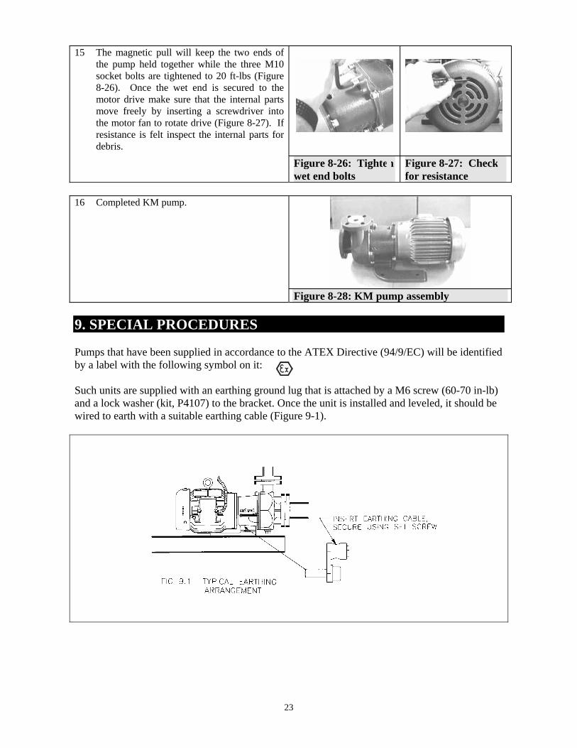
15 The magnetic pull will keep the two ends of
the pump held together while the three M10 socket bolts are tightened to 20 ft-lbs (Figure 8-26). Once the wet end is secured to the motor drive make sure that the internal parts move freely by inserting a screwdriver into the motor fan to rotate drive (Figure 8-27). If resistance is felt inspect the internal parts for debris.
Figure 8-26: Tighten wet end bolts
Figure 8-27: Check for resistance
16 Completed KM pump.
Figure 8-28: KM pump assembly 9. SPECIAL PROCEDURES Pumps that have been supplied in accordance to the ATEX Directive (94/9/EC) will be identified by a label with the following symbol on it: Such units are supplied with an earthing ground lug that is attached by a M6 screw (60-70 in-lb) and a lock washer (kit, P4107) to the bracket. Once the unit is installed and leveled, it should be wired to earth with a suitable earthing cable (Figure 9-1).
24
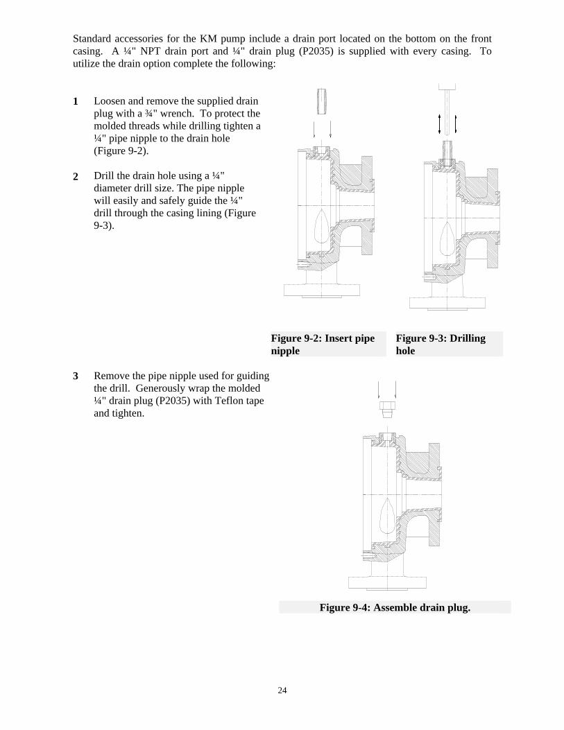
Standard accessories for the KM pump include a drain port located on the bottom on the front casing. A ¼" NPT drain port and ¼" drain plug (P2035) is supplied with every casing. To utilize the drain option complete the following: 1 2
Loosen and remove the supplied drain plug with a ¾" wrench. To protect the molded threads while drilling tighten a ¼" pipe nipple to the drain hole (Figure 9-2). Drill the drain hole using a ¼" diameter drill size. The pipe nipple will easily and safely guide the ¼" drill through the casing lining (Figure 9-3).
Figure 9-2: Insert pipe nipple
Figure 9-3: Drilling hole
3
Remove the pipe nipple used for guiding the drill. Generously wrap the molded ¼" drain plug (P2035) with Teflon tape and tighten.
Figure 9-4: Assemble drain plug.
25
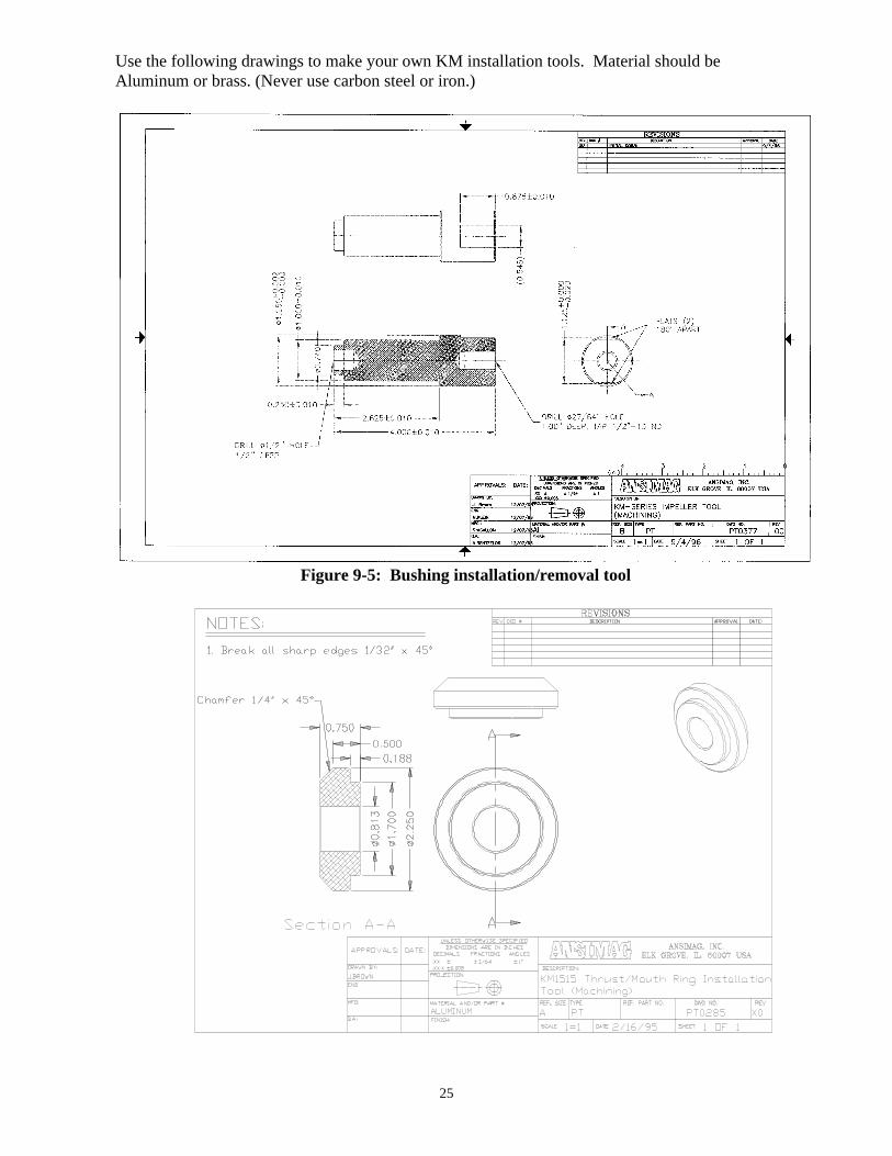
Use the following drawings to make your own KM installation tools. Material should be Aluminum or brass. (Never use carbon steel or iron.)
Figure 9-5: Bushing installation/removal tool

26
10. DRAWINGS 10-a Dimensional Drawings
Figure 10-1: KM dimensional drawing Dimension Table
Model Suct. Dis. W X Y Z F F1 F2 F3 LJ WB CP L KM1515 (mm)
1 ½ (40)
1 (25)
10 (254)
5.50 (140)
3.15 (80)
2.34 (59)
3.58 (91)
5.31 (135)
5.31 (171)
13.86 (344)
5.50 (140)
8.00 (203)
9.92 (252)
20 (508)
KM2156 (mm)
2 (50)
1 ½ (40)
10 (254)
5.50 (140)
3.42 (87)
2.56 (65)
3.79 (96)
5.58 (144)
7.22 (183)
13.96 (354)
5.50 (140)
8.00 (203)
11.50 (292)
23 (584)
Table 10-1 Note: For Reference only! Some dimensions may vary slightly with different motor sizes.
27
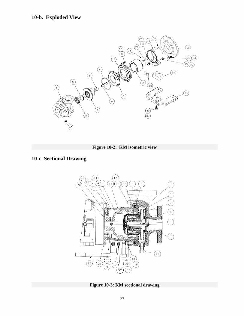
10-b. Exploded View
Figure 10-2: KM isometric view 10-c Sectional Drawing
Figure 10-3: KM sectional drawing

28
11. PARTS LIST Recommended Spare Parts for all levels of service.
Item# Part Name Qty KM1515 Part # KM2156 Part #
1 Casing Ductile Iron lined ETFE
Ductile Iron lined GFR-PFA 316L Stainless Steel
Hastelloy C
1 P2055A P2055B P2308A P2308B
P2735A P2735B
N/A N/A
2 Impeller AA and AB-drive, CFR-ETFE AA and AB-drive, GFR-PFA
1 P2258A P2258B
P2861A P2861B
3 Containment Shell CFR-ETFE GFR-PFA
1 P2056A P2056B
P2862A P2862B
5 Mouth Ring CFR-PTFE
SiC
1 P2063 P2285
K0501 K0506
6 Shaft - SiC 1 P2060 P2738 8 Casing O-ring
Viton®
EPDM Teflon®-Viton® wrapped Gore-Tex®
1 P2339A P2339B P2339C
P2339D P2339E P2339F
9 Main Bushing Carbon
SiC
1 P1997 P1996
P1997 P1996
11 Shaft Support/Thrust Ring CFR-ETFE/SiC
GFR-PFA/SiC
1 P2066A P2066B
K1102
K1102P 12 Rear Support
Ductile Iron 316 Stainless Steel
1 P2058
P2371A
P2749 N/A
13 Bracket 1 P2104 P2104 14 Outer Drive
AA Drive 56C frame (NEMA)
143/145TC frame (NEMA) 182/184TC frame (NEMA) 213/215TC frame (NEMA)
80 frame (IEC) 90 frame (IEC)
100/112 frame (IEC) 132 frame (IEC)
AB Drive 182/184TC frame (NEMA) 213/215TC frame (NEMA)
100/112 frame (IEC) 132 frame (IEC)
1
P2172D P2172A P2172B
P2172E P2172F P2172G
P2172I P2172C P2172J P2172H
P2172D P2172A P2172B P2172C P2172E P2172F P2172G P2172H
P2172I P2172C P2172J P2172H
15 Bracket Foot 1 P1942 P1942 17 Lock Washer 6 HLM10 HLM12 18 Hex Bolt, Rear Support/Pump Case 6 HSM10X20 HHM12X30

29
Item# Part Name Qty KM1515 Part # KM2156 Part # 19
16 Socket Bolt, Bracket/Rear Support Lock Washer
7 7
HSM10X20 HLM10
HSM10X20 HLM10
21 Motor Mounting Plate 56C & 143/145TC frame (NEMA)
182/184TC & 213/215TC frame (NEMA)
80/90 frame (IEC) 100/112 frame (IEC)
132 frame (IEC)
1 P2095 P2093 P2096 P2097
P2095 P2093 P2096 P2097 P2508
25 Jack Screws 2 HSM 10 x 40 HSM 10 x 40 34 Riser, Bracket Foot
All All except 100 frame IEC
100 frame IEC (only)
1 1 1
NA NA
P2726
P2792
35 Hex Bolt, Bracket Foot All
All except 100 frame IEC 100 frame IEC only
3 3 3
HHM12X25 HHM12X60
HHM12X60
37 Lock Washer 3 HLM12 HLM12 51 Name Plate, ATEX / CE 1 P4070 P4070 55 Earthing Kit, Grounding Lug 1 P4107 P4107 65 Drain Plug 1/4" NPT, Pump Case
Carbon Filled Tefzel® Glass Filled PFA
1 P2035A P2035B
P2035A P2035B
73 Drain Plug, Bracket 1 K3903-Z K3903-Z 74 Set Screw Plug, Bracket 1 K3903-Z K3903-Z 75 Set Screw, Outer Drive 2 K1601 K1601 76 Motor Shaft Key
56C frame (NEMA) 14_frame (NEMA) 18_frame (NEMA) 21_frame (NEMA)
80 frame (IEC) 90 frame (IEC)
100/112 frame (IEC) 132 frame (IEC)
1 P2200A P2200B P2200C
P2200D P2200E P2200F
P2200A P2200B P2200C P2200G P2200D P2200E P2200F P2200H

30
12. PUMP SPECIFICATIONS KM1515 KM2156 hp: • 5 hp max. • 7.5 hp max. Temperature: • 250°F max. -20°F min. • 250°F max. -20°F min. Pressure: • 150 psi (Hydrostatic 225 psi) • 150 psi (Hydrostatic 225 psi) Viscosity: • 700 SSU (150 centistokes) max. • 700 SSU (150 centistokes) max. Minimum Flow: • 1 gpm at 3600 rpm • 1 gpm at 3600 rpm Port size: • Sub-ANSI 1-1/2" x 1" x 5.00"
ISO 40 x 25 x 127mm JIS 40 x 25 x 127mm
• Sub-ANSI 2 x 1-1/2" x 6.00" ISO 50 x 40 x 152mm JIS 50 x 40 x 152mm
Solids: • 500 microns max., 0.5% by weight max.
• 500 microns max., 0.5% by weight max.
Impeller: • 5.00" (127mm) 3.00" trimmed • 6.00" (152mm) 3.00" trimmed Mounting: • Close coupled NEMA and IEC • Close coupled NEMA and IEC Ship Weight • 53 lbs (24 kg) standard pump
end without motor • 70 lbs (24 kg) standard pump
end without motor 13. COMMON CONVERSIONS Flow (Capacity)
gpm (US) m3/h L/min gpm (UK) 1 0.2271 3.785 0.8327
4.403 1 16.6667 3.666 0.2642 0.06 1 0.22 1.201 0.2727 4.5458 1
Volume
ft3 m3 liter gallon (US) gallon (UK) lbs of water 1 0.02832 28.32 7.481 6.229 62.44
35.31 1 1000 264.2 220.00 2205 0.03531 0.001 1 0.2642 0.22 2.205 0.1337 0.003785 3.785 1 0.8327 8.347 0.1606 0.004545 4.548 1.201 1 10.025 0.01620 0.0004536 0.4536 .1198 0.09975 1
Head ( Pressure / Vacuum )
ft (H²O) m (H²O) psi kg/cm2 KPa inch Hg mmHg bar 1 0.3048 0.4335 0.03047 2.989 0.8826 22.42 0.02988
3.281 1 1.423 0.1 9.807 2.896 73.55 0.0981 2.307 0.7031 1 0.07029 6.895 2.036 51.71 0.0690 32.83 10.01 14.23 1 98.07 28.96 735.5 .981
0.3346 0.1020 0.145 0.0102 1 0.2953 7.501 0.01 1.133 0.3453 0.491 0.0345 3.386 1 25.4 0.0339
0.0446 0.0136 0.01933 0.001356 0.1330 0.03937 1 0.00133 33.458 10.195 14.504 1.01956 100 29.5 750.1 1


ANSIMAG 14845 W. 64th Avenue Arvada, CO 80007 USA Phone: (303)425-0800 Fax: (303)425-0896 www.sundyne.com


![[TYTUŁ DOKUMENTU] - Tapflo UK Filter Units IOM.pdf · [TYTUŁ DOKUMENTU] [Podtytuł dokumentu] FTA Filter Units ... FTA160 FTA210 6 rev 1 Read this instruction manual carefully,](https://img.pdfslide.us/doc/110x75/5b4dd0677f8b9a0b448b5883/tytul-dokumentu-tapflo-uk-filter-units-iompdf-tytul-dokumentu-podtytul.jpg)