Embed Size (px)
Citation preview
801525 - Zip HydroTap Installation Instructions - Nov. 2013 - V1.00 Page 1 of 16
Zip HydroTap Installation Instructions
Affix Model Number Label
Here
801525
Filtered Chilled drinking water for commercial kitchens and tea rooms.
®
Page 2 of 16 801525 - Zip HydroTap Installation Instructions - Nov. 2013 - V1.00
HydroTap SpecificationsInstallation check list .................................................................................................................... 3
General Product Features ............................................................................................................ 4
Important Safety Instructions ....................................................................................................... 5
Warnings and Regulatory Information .......................................................................................... 6
Major components and Accessories ............................................................................................ 6
Technical Specification ................................................................................................................ 7
Before installation and site requirements ..................................................................................... 7
Installation Instructions
STEP 1 - Measure and cut all the tap holes before fitting the taps
Section 1 - Tap Installation instructions
1.1 - HydroTap Tap installation ......................................................................................... 8-10
STEP 2 - Check for adequate ventilation
Section 2 - Ventilation
2.1- Details ........................................................................................................................ 11-12
STEP 3 - Install the undersink unit
Section 3 - Undersink Unit Installation
3.1- Fit the mains water supply hose ................................................................................ 13
3.2- Model C 125 and C 175 ............................................................................................. 13
STEP 4 - Commission the HydroTap
Section 4 - Commissioning
4.1- Filter flush .................................................................................................................. 14
4.2- Flow Calibration ......................................................................................................... 14
Trouble ShootingTrouble Shooting Table ................................................................................................................ 15
End of life disposal ....................................................................................................................... 15
Contact details ............................................................................................................................. 16
Index
801525 - Zip HydroTap Installation Instructions - Nov. 2013 - V1.00 Page 3 of 16
Before Installation:
A. Read the instructions and check if there is adequate space to mount all of the components.
B. Note: Not all fittings are supplied with the appliance kit. Isolation valves are not supplied.
C. Check the mains water pressure is between 172 - 700kPa
D. Check the water quality to determine if extra filtration will be required.
E. Check the appliance rating plate and ensure correct power is available for the appliance.
F. Check the under counter cupboard supporting the appliance is adequate for
the total weight of the appliance, when full of water.
Before Commissioning:
1. Check the unit has been installed correctly.
2. Check all plumbing fittings have been tightened.
3. Ensure the outlet pipe is positioned to drain correctly.
4. Ensure there is adequate ventilation.
5. Check all tubes from the undersink unit to the tap, have a constant rise and there are no
sags or kinks in the hoses.
6. Check all electrical connections are correct and there are no loose wires.
Commission: (See section 4)
7. Flush the supply line before connecting.
8. Connect and turn on the water to check for leaks.
9. Flush the filter.
10. Where applicable, programme the unit to suit the customer’s requirements.
Installation checklist
Page 4 of 16 801525 - Zip HydroTap Installation Instructions - Nov. 2013 - V1.00
Thank you for purchasing a Zip Chilled HydroTap. Please read and follow these instructions carefully to ensure
safe operation and trouble free service. If service is required, please call 1800 460 222
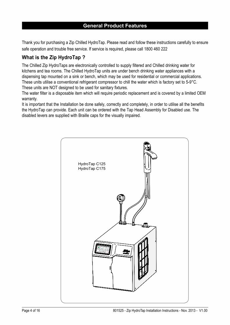
What is the Zip HydroTap ?
The Chilled Zip HydroTaps are electronically controlled to supply filtered and Chilled drinking water for
kitchens and tea rooms. The Chilled HydroTap units are under bench drinking water appliances with a
dispensing tap mounted on a sink or bench, which may be used for residential or commercial applications.
These units utilise a conventional refrigerant compressor to chill the water which is factory set to 5-9°C.
These units are NOT designed to be used for sanitary fixtures.
The water filter is a disposable item which will require periodic replacement and is covered by a limited OEM
warranty.
It is important that the Installation be done safely, correctly and completely, in order to utilise all the benefits
the HydroTap can provide. Each unit can be ordered with the Tap Head Assembly for Disabled use. The
disabled levers are supplied with Braille caps for the visually impaired.
General Product Features
HydroTap C125
HydroTap C175
801525 - Zip HydroTap Installation Instructions - Nov. 2013 - V1.00 Page 5 of 16
Important Safety Instructions
This manual contains important safety, installation instructions for the Zip HydroTap G4.
This appliance is not intended for use by persons (including children) with reduced physical,
sensory or mental capabilities, or lack of experience and knowledge, unless they have been
given supervision or instruction concerning use of the appliance by a person responsible for
their safety. Children should be supervised to ensure that they do not play with the appliance.
For products sold in Europe, this appliance can be used by children aged from 8 years and above and
persons with reduced physical, sensory or mental capabilities or lack of experience and knowledge if they
have been given supervision or instruction concerning use of the appliance in a safe way and understand
the hazards involved. Children shall not play with the appliance. Cleaning and user maintenance shall not be
made by children without supervision.
Qualifications
If the power cable is damaged it must be repaired only by a qualified technician. To avoid hazards, all
installation procedures must be carried out by a suitably qualified tradesperson. The power cable and power
outlet must be in a safe visible position for connection.
Lifting
Take care when lifting the Zip HydroTap unit. Some units may exceed safe lifting limits. If you feel this is
beyond your personal capabilities, please seek assistance with the lift. The weights of the units are marked
on the packaging. Do not lift the unit by the front cover or any connections at the top rear of the unit. Refer to
page 7 for the weight of your product.
Airflow
The ambient temperatures this unit should operate within are 5ºC - 35ºC. Proper air circulation must be
provided. The system will operate satisfactorily only if the recommended air gaps are provided. See technical
specifications for correct installation to prevent overheating.
Positioning
It is important to ensure the undersink unit is positioned in an accessible area close to the floor level. The unit
must have it’s base mounted in a horizontal position with all inlets and outlets facing up. The Tap must be
located above the undersink unit. See page 9 and 13 for details.xposed to the elements of nature. This
unit must not be positioned in an area that may be cleaned by a water jet and must not be cleaned
by a water jet.
Page 6 of 16 801525 - Zip HydroTap Installation Instructions - Nov. 2013 - V1.00
Major components and accessories
Important Safety Instructions
WARNINGS
1. The Zip HydroTap unit must be earthed. The resistance of the earth connection from each exposed
metal part must be less than 1 ohm.
2. All Installation and service work must be completed by trained and suitably qualified Tradespeople.
Faulty operation due to unqualified persons working on this product, or any other Zip product may void
warranty coverage.
3. All Plumbing must comply with AS/NZS3500.
4. All Electrical must comply with AS/NZS3000
5. All Plumbing and Electrical connections must be made in accordance with local regulations.
6. This HydroTap product is rated for 230V 50Hz AC operation.
7. Undersink units must never be located near, or cleaned with water jets.
8. Zip HydroTaps are not to be exposed to the elements of nature
9. Due to the process of continuous improvement, Zip Heaters reserves the right to change details
mentioned in this manual, without notice.
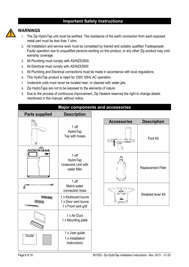
Parts supplied Description
1 off
HydroTap
Tap with hoses
1 off
HydroTap
Undersink Unit with
water filter
1 off
Mains water
connection hose
1 x Kickboard louvre
1 x Door vent louvre
1 x Front vent grill
1 x Air Duct
1 x Mounting plate
1 x User guide
1 x Installation
Instructions
Accessories Description
Font Kit
Replacement Filter
Disabled lever Kit
Guide
801525 - Zip HydroTap Installation Instructions - Nov. 2013 - V1.00 Page 7 of 16
Before installing ensure that the following have been provided at the
installation site:
• Review all the technical specifications.
• Ensure the underbench can support the product weight when full of water,
(allow an extra 3-4kg when full. )
• Sufficient space in the cupboard to install all of the undersink units in accordance with these
Installation Instructions. Refer to technical specification for dimensions. Refer to section 3 & 4, for
Installation instructions.
• The chilled HydroTap models require a 220-240 Vac, 10A GPO
NOTE: Check all cable and hose lengths against inlet /outlet positions before
proceeding (See section 5 for general layout).
• A potable water supply connection with isolating valve inside the cupboard within reach of the
braided hoses and positioned so that the connection point and the stop cock will not be obstructed
when the undersink units are installed.
• A cold water supply with a minimum working pressure of 172kPa and a maximum working pressure
of 700kPa connected via an isolation valve.
• The appliance must be placed with it’s base in a horizontal position.
IMPORTANT! Do not proceed with the Installation if these requirements are not met.
Technical Specifications
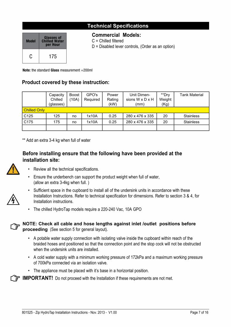
Commercial Models:C = Chilled filtered
D = Disabled lever controls, (Order as an option)
ModelGlasses of
Chilled Water per Hour
C 175
Note: the standard Glass measurement =200ml
Product covered by these instruction:
** Add an extra 3-4 kg when full of water
Capacity
Chilled
(glasses)
Boost
(10A)
GPO's
Required
Power
Rating
(kW)
Unit Dimen-
sions W x D x H
(mm)
**Dry
Weight
(Kg)
Tank Material
Chilled Only
C125 125 no 1x10A 0.25 280 x 476 x 335 20 Stainless
C175 175 no 1x10A 0.25 280 x 476 x 335 20 Stainless
Page 8 of 16 801525 - Zip HydroTap Installation Instructions - Nov. 2013 - V1.00
Special Tools Required:
In addition to normal tools, the following will be required:
For the standard taps:
• 35mm diameter sheet metal hole punch for sink tops. (Not supplied)
• 35mm diameter hole saw for timber bench tops. (Not supplied)
• Nut runner tube spanner (supplied) for fixing tap assembly.
When installing a font unit, the following will be required:
• 108mm diameter sheet metal or hole saw to suit surface being cut.
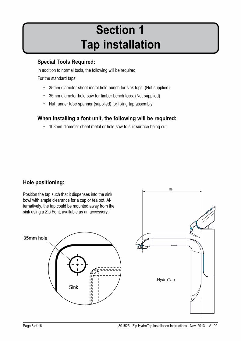
Hole positioning:
Position the tap such that it dispenses into the sink
bowl with ample clearance for a cup or tea pot. Al-
ternatively, the tap could be mounted away from the
sink using a Zip Font, available as an accessory.
Section 1
Tap installation
35mm hole
116
Sink
HydroTap
801525 - Zip HydroTap Installation Instructions - Nov. 2013 - V1.00 Page 9 of 16
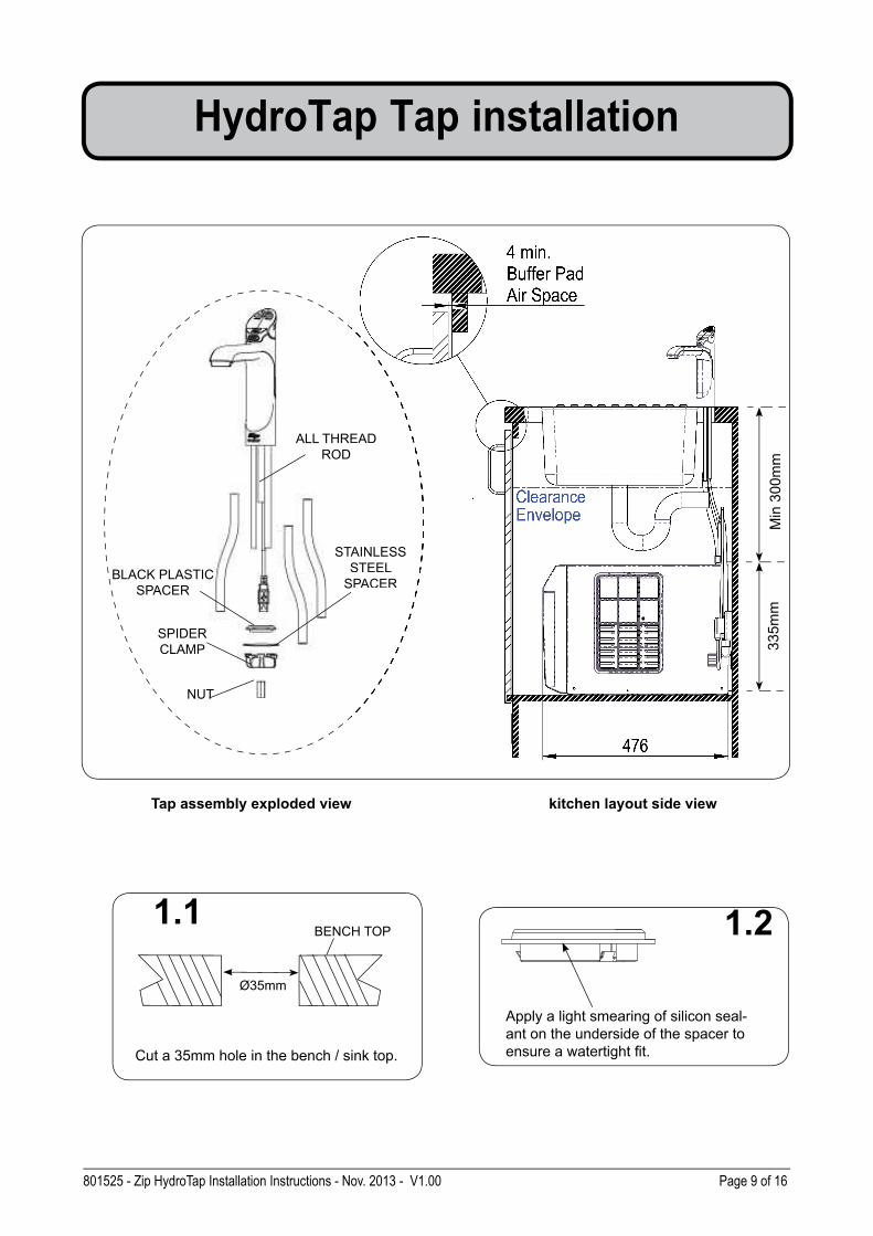
Apply a light smearing of silicon seal-
ant on the underside of the spacer to
ensure a watertight fi t.
1.2
Cut a 35mm hole in the bench / sink top.
BENCH TOP1.1
Ø35mm
Min
30
0m
m
ALL THREAD
ROD
STAINLESS
STEEL
SPACER
SPIDER
CLAMP
NUT
BLACK PLASTIC
SPACER
Tap assembly exploded view
33
5m
m
HydroTap Tap installation
kitchen layout side view
READ
STAINLESS
STEEL
SPACER
Page 10 of 16 801525 - Zip HydroTap Installation Instructions - Nov. 2013 - V1.00
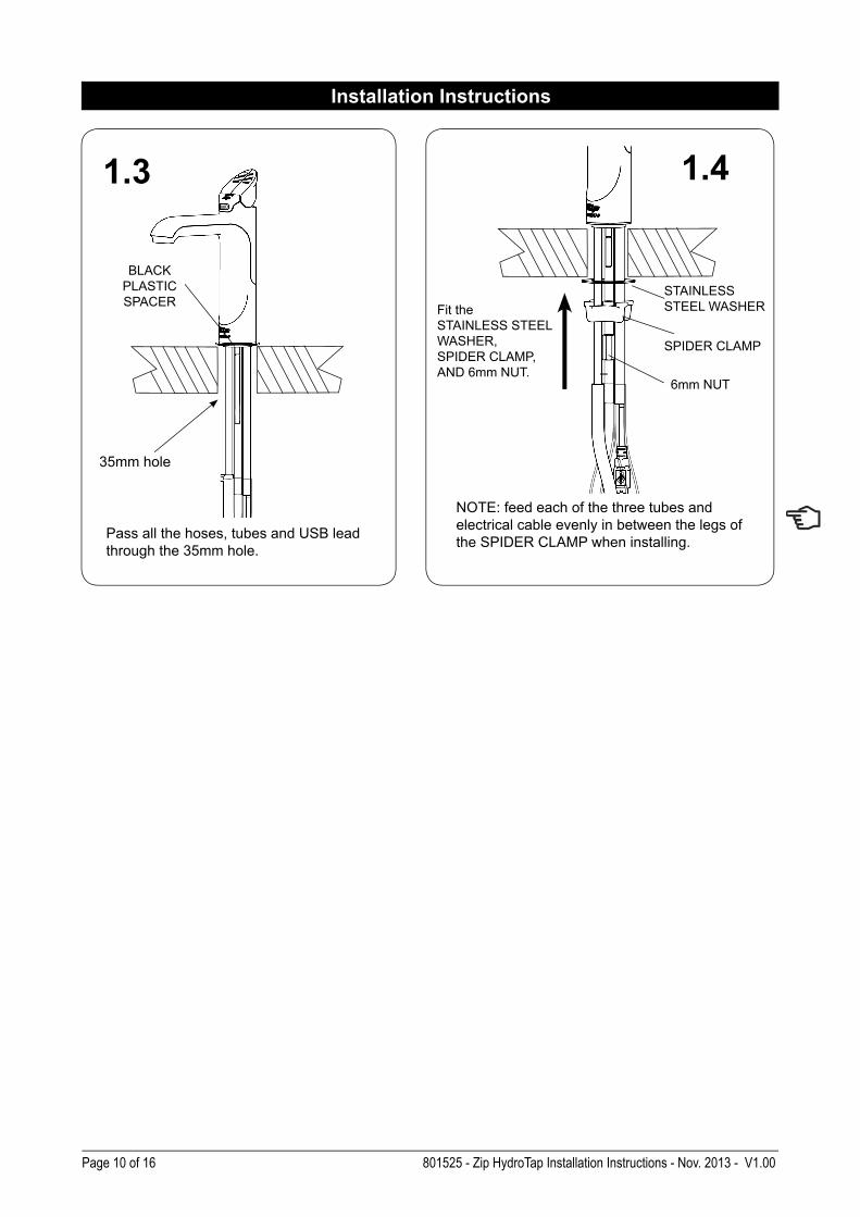
BLACK
PLASTIC
SPACER
1.3
Installation Instructions
Pass all the hoses, tubes and USB lead
through the 35mm hole.
1.4
35mm hole
NOTE: feed each of the three tubes and
electrical cable evenly in between the legs of
the SPIDER CLAMP when installing.
Fit the
STAINLESS STEEL
WASHER,
SPIDER CLAMP,
AND 6mm NUT. 6mm NUT
SPIDER CLAMP
STAINLESS
STEEL WASHER
801525 - Zip HydroTap Installation Instructions - Nov. 2013 - V1.00 Page 11 of 16
Section 2
Ventilation
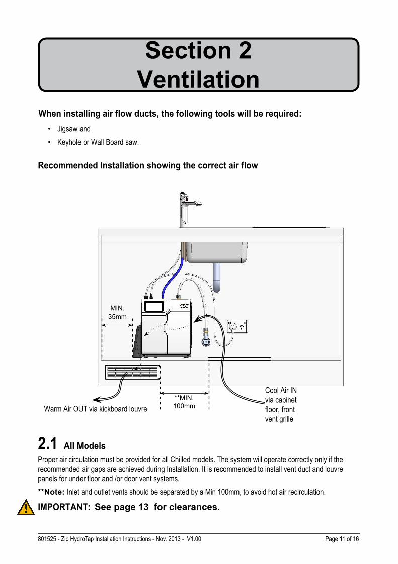
2.1 All Models
Proper air circulation must be provided for all Chilled models. The system will operate correctly only if the
recommended air gaps are achieved during Installation. It is recommended to install vent duct and louvre
panels for under floor and /or door vent systems.
**Note: Inlet and outlet vents should be separated by a Min 100mm, to avoid hot air recirculation.
IMPORTANT: See page 13 for clearances.
When installing air flow ducts, the following tools will be required:
• Jigsaw and
• Keyhole or Wall Board saw.
Recommended Installation showing the correct air flow
**MIN.
100mmWarm Air OUT via kickboard louvre
MIN.
35mm
Cool Air IN
via cabinet
floor, front
vent grille
Page 12 of 16 801525 - Zip HydroTap Installation Instructions - Nov. 2013 - V1.00
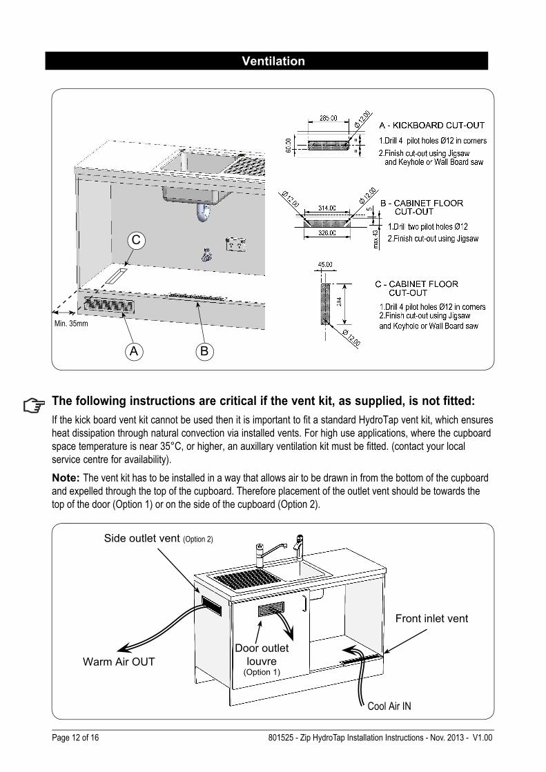
The following instructions are critical if the vent kit, as supplied, is not fitted:
If the kick board vent kit cannot be used then it is important to fit a standard HydroTap vent kit, which ensures
heat dissipation through natural convection via installed vents. For high use applications, where the cupboard
space temperature is near 35°C, or higher, an auxillary ventilation kit must be fitted. (contact your local
service centre for availability).
Note: The vent kit has to be installed in a way that allows air to be drawn in from the bottom of the cupboard
and expelled through the top of the cupboard. Therefore placement of the outlet vent should be towards the
top of the door (Option 1) or on the side of the cupboard (Option 2).
A B
C
Min. 35mm
Side outlet vent (Option 2)
Door outlet
louvre (Option 1)
Front inlet vent
Cool Air IN
Warm Air OUT
Ventilation
801525 - Zip HydroTap Installation Instructions - Nov. 2013 - V1.00 Page 13 of 16
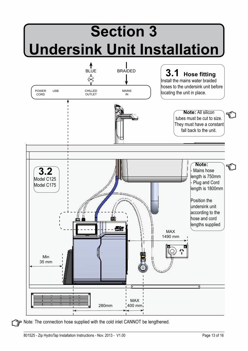
Note: The connection hose supplied with the cold inlet CANNOT be lengthened.
POWER
CORD
USB CHILLED
OUTLET
MAINS
IN
Note: All silicon
tubes must be cut to size.
They must have a constant
fall back to the unit.
Section 3
Undersink Unit Installation
BLUE BRAIDED 3.1 Hose fitting Install the mains water braided
hoses to the undersink unit before
locating the unit in place.
280mm
MAX
1490 mm
MAX
400 mm
Min
35 mm
Note:
- Mains hose
length is 750mm
- Plug and Cord
length is 1800mm
Position the
undersink unit
according to the
hose and cord
lengths supplied
3.2Model C125
Model C175
Page 14 of 16 801525 - Zip HydroTap Installation Instructions - Nov. 2013 - V1.00
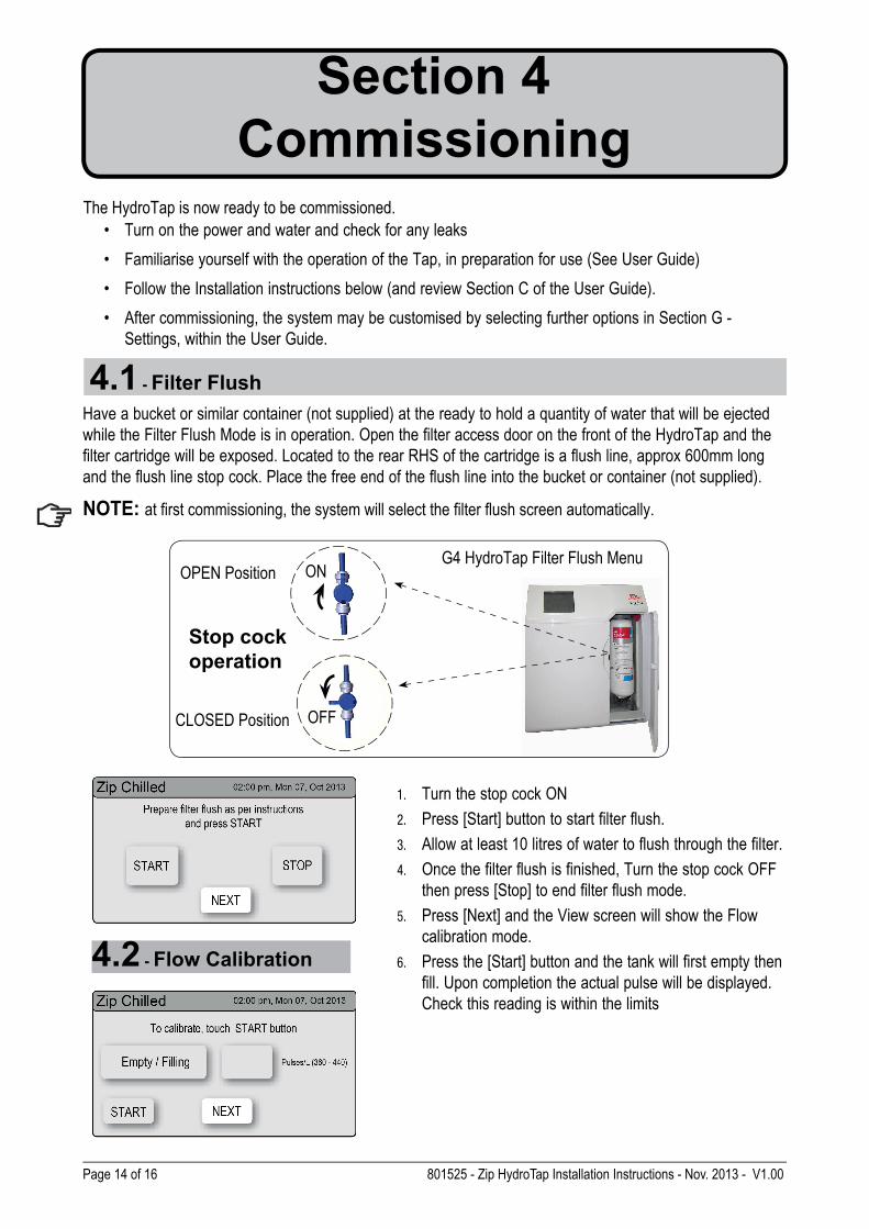
Section 4
CommissioningThe HydroTap is now ready to be commissioned.
• Turn on the power and water and check for any leaks
• Familiarise yourself with the operation of the Tap, in preparation for use (See User Guide)
• Follow the Installation instructions below (and review Section C of the User Guide).
• After commissioning, the system may be customised by selecting further options in Section G -
Settings, within the User Guide.
1. Turn the stop cock ON
2. Press [Start] button to start filter flush.
3. Allow at least 10 litres of water to flush through the filter.
4. Once the filter flush is finished, Turn the stop cock OFF
then press [Stop] to end filter flush mode.
5. Press [Next] and the View screen will show the Flow
calibration mode.
6. Press the [Start] button and the tank will first empty then
fill. Upon completion the actual pulse will be displayed.
Check this reading is within the limits
Have a bucket or similar container (not supplied) at the ready to hold a quantity of water that will be ejected
while the Filter Flush Mode is in operation. Open the filter access door on the front of the HydroTap and the
filter cartridge will be exposed. Located to the rear RHS of the cartridge is a flush line, approx 600mm long
and the flush line stop cock. Place the free end of the flush line into the bucket or container (not supplied).
NOTE: at first commissioning, the system will select the filter flush screen automatically.
4.1 - Filter Flush
4.2 - Flow Calibration
OPEN Position
CLOSED Position
ON
OFF
G4 HydroTap Filter Flush Menu
Stop cock
operation
801525 - Zip HydroTap Installation Instructions - Nov. 2013 - V1.00 Page 15 of 16
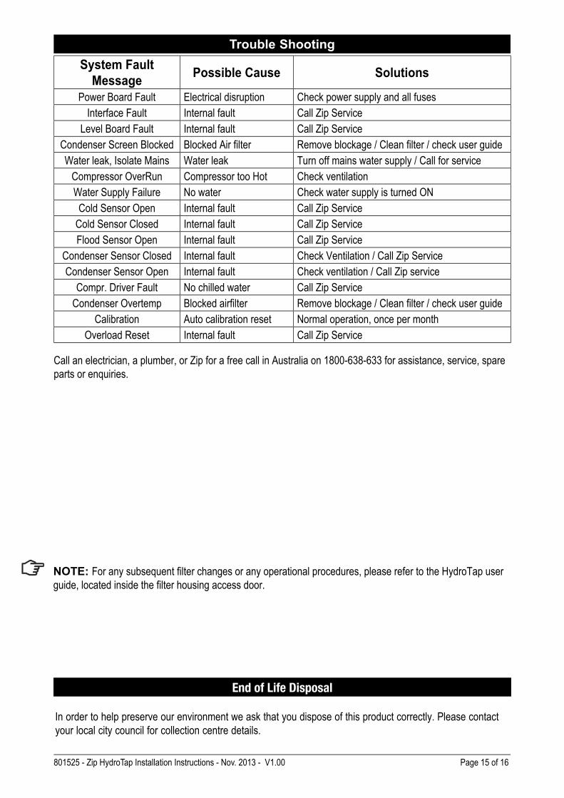
Trouble Shooting
In order to help preserve our environment we ask that you dispose of this product correctly. Please contact
your local city council for collection centre details.
End of Life Disposal
NOTE: For any subsequent fi lter changes or any operational procedures, please refer to the HydroTap user
guide, located inside the fi lter housing access door.
System Fault
MessagePossible Cause Solutions
Power Board Fault Electrical disruption Check power supply and all fuses
Interface Fault Internal fault Call Zip Service
Level Board Fault Internal fault Call Zip Service
Condenser Screen Blocked Blocked Air filter Remove blockage / Clean filter / check user guide
Water leak, Isolate Mains Water leak Turn off mains water supply / Call for service
Compressor OverRun Compressor too Hot Check ventilation
Water Supply Failure No water Check water supply is turned ON
Cold Sensor Open Internal fault Call Zip Service
Cold Sensor Closed Internal fault Call Zip Service
Flood Sensor Open Internal fault Call Zip Service
Condenser Sensor Closed Internal fault Check Ventilation / Call Zip Service
Condenser Sensor Open Internal fault Check ventilation / Call Zip service
Compr. Driver Fault No chilled water Call Zip Service
Condenser Overtemp Blocked airfilter Remove blockage / Clean filter / check user guide
Calibration Auto calibration reset Normal operation, once per month
Overload Reset Internal fault Call Zip Service
Call an electrician, a plumber, or Zip for a free call in Australia on 1800-638-633 for assistance, service, spare
parts or enquiries.
Page 16 of 16 801525 - Zip HydroTap Installation Instructions - Nov. 2013 - V1.00
Contact Details
The standard cup referred to in this publication is 167 ml (6 fl oz).
The standard glass is 200 ml (7 fl oz).
The terms “Zip” and “HydroTap” are registered trade marks of Zip Heaters
(Aust) Pty Ltd.
Zip products described in this publication are manufactured under one or more
of the following patents: AU675601, AU637412, AU635979, GB0422305,
GB2065848, US4354049, US5103859, US5099825 and SA2006/08043. Other
patents are in force and patent applications are pending.
Head Office
Zip Heaters (Aust) Pty. Ltd.
ABN: 46 000 578 727
67 Allingham Street
Condell Park NSW 2200
Postal: Locked Bag 80
Bankstown 1885 Australia
Website: www.zipheaters.com
Facsimile: (02) 9796 3858
Telephone: (02) 9796 3100
Free Call: 1 800 638 633
As Zip policy is one of continuous product improvement, changes to
specifications may be made without prior notice. Images in this booklet have
been modified and may not be true representations of the finished goods.WMKA00099
AS 3498