Embed Size (px)
Citation preview
CRLPELEV001A00--CRLPELEV004A00,CRLPELEV007A00--CRLPELEV009A00
Installation Instructions
SMALL ROOFTOP UNITSACCESSORY LP (LIQUID PROPANE)
HIGH ALTITUDE GAS CONVERSION KITGAS HEATING/ELECTRIC COOLING
3 to 15 TONSizes 04 to 16 and 036 to 180
60,000--350,000 Btu/hr
TABLE OF CONTENTSPACKAGE CONTENTS 1. . . . . . . . . . . . . . . . . . . . . . . . .
SAFETY CONSIDERATIONS 2. . . . . . . . . . . . . . . . . . . .
GENERAL 2. . . . . . . . . . . . . . . . . . . . . . . . . . . . . . . . . . . .
LP CONVERSION KIT INSTALLATION 3. . . . . . . . . . .Step 1 -- Remove Burner Section from Base Unit 3. . . . . . . . . .
Step 2 -- Modify Burner/Valve Assembly 4. . . . . . . . . . . . . . . . .
Step 3 -- Re--install Burner Assembly 6. . . . . . . . . . . . . . . . . . . .
Step 5 -- Check Unit Operation and Make NecessaryAdjustments 7. . . . . . . . . . . . . . . . . . . . . . . . . . . . . . . .
HIGH ALTITUDE CONVERSION KITINSTALLATION 8. . . . . . . . . . . . . . . . . . . . . . . . . . . . . . .Step 1 -- Remove Burner Section from Base Unit 8. . . . . . . . . .
Step 2 -- Modify Burner/Valve Assembly 8. . . . . . . . . . . . . . . . .
Step 3 -- Re--install Burner Assembly 8. . . . . . . . . . . . . . . . . . . .
Step 4 -- Check Unit Operation and Make NecessaryAdjustments 9. . . . . . . . . . . . . . . . . . . . . . . . . . . . . . . .
ALTITUDE COMPENSATION TABLES 10. . . . . . . . . .IMPORTANT: Read these instructions completely beforeattempting to install this accessory.IMPORTANT: The accessories described in thisinstallation instructions manual are suitable for use on themodels listed below. DO NOT ATTEMPT TO INSTALLON MODELS AND SIZES NOT INCLUDED IN THESETABLES.
Table 1 – Unit Usage
CARRIER MODELSCheck positions 7--8 on unit dataplate for unit size.MODEL UNIT SIZES NOMINAL TONS48HC 04---14 3---12.548KC 04---06 3---548LC 04---12 3---1048TC 04---16 3---15
BRYANT MODELSCheck positions 6--7 on unit dataplate for unit size.MODEL UNIT SIZES NOMINAL TONS580J 04---16 3---15581J 04---14 3---12.5582J 04---06 3---5
ICP MODELSCheck positions 4--5--6 on unit dataplate for unit size.MODEL UNIT SIZES NOMINAL TONSRGH 036---150 3---12.5RGS 036---180 3---15RGX 036---060 3---5
PACKAGE CONTENTSLP (LIQUID PROPANE) AND HIGH
ALTITUDE KITACCESSORYPART NO.
ORIFICESSIZE QTY PART NUMBER
CRLPELEV003A00(LP Only)
46 5 LH32RF08047 5 LH32RF07948 5 LH32RF07649 5 LH32RF07350 5 LH32RF070
CRLPELEV004A00(LP Only)
51 5 LH32RF06752 5 LH32RF06553 5 LH32RF06054 5 LH32RF05555 5 LH32RF052
CRLPELEV009A00(LP Only)
51 10 LH32RF06752 10 LH32RF06553 10 LH32RF06054 10 LH32RF05555 10 LH32RF052
COMMON CONTENTS QTY PART NUMBERINSTRUCTIONS 1 IIK-CRLPELEV01-06ELBOW, 1/8” NPT x 90° 1 CA05RA001ELBOW, STREET 1/8” NPT x 90° 1 CA15RA001NIPPLE, 1/8” PIPE x 3/4” 1 CA01CA001NIPPLE, 1/8” PIPE x 1-1/2” 1 CA01CA006NIPPLE, 1/8” PIPE x 3-1/2” 1 CA01CA020SWITCH, LP PRESSURE 1 HK02LB008WIRE, BROWN 1 99WG7373XC200918SPRINGS, LP CONVERSION 2 EF39ZW023LABEL, LP CONVERSION KIT RAT-ING PLATE 1 48TM502595
LABEL, LP RESPONSIBILITY 1 48TM501014LABEL, HIGH-ALT. RESPONSIBILITY 1 48TM501015
Package Contents CRLPELEV003 and 004A00 OnlyCRLPELEV003, 004A00 ONLY QTY PART NUMBER
LABEL, GAS VALVE LP CONV 1 48TM501013LABEL, UNIT WARNING (LP) 1 48TM501012
Package Contents CRLPELEV009A00 OnlyCRLPELEV009A00 ONLY QTY PART NUMBER
LABEL, GAS VALVE LP CONV 1 48TM504835LABEL, UNIT WARNING (LP) 1 48TM504836SWITCH, TEMPERATURE ACTUAT-ED 1 HH18HA147
2
PACKAGE CONTENTSHIGH ALTITUDE KIT(NATURAL GAS)
ACCESSORYPART NO.
ORIFICESSIZE QTY PART NUMBER
CRLPELEV001A00(Natural Gas Only)
31 5 LH32RF12032 5 LH32RF11633 5 LH32RF11335 5 LH32RF11036 5 LH32RF105
CRLPELEV002A00(Natural Gas Only)
37 5 LH32RF10438 5 LH32RF10239 5 LH32RF10344 5 LH32RF08645 5 LH32RF082
CRLPELEV007A00(Natural Gas Only)
36 10 LH32RF10537 10 LH32RF10438 10 LH32RF10239 10 LH32RF103
CRLPELEV008A00(Natural Gas Only)
40 10 LH32RF09841 10 LH32RF09642 10 LH32RF09443 10 LH32RF089
COMMON CONTENTS QTY PART NUMBERINSTRUCTIONS 1 IIK ---CRLPELEV01---06
LABEL, HIGH---ALT. RESPONSIBILITY 1 48TM501015LABEL, NG CONVERSION KIT RATING
PLATE 1 48TM502594
SAFETY CONSIDERATIONSInstallation and servicing of air--conditioning equipmentcan be hazardous due to system pressure and electricalcomponents. Only trained and qualified service personnelshould install, repair, or service air--conditioningequipment.Untrained personnel can perform the basic maintenancefunctions. All other operations should be performed bytrained service personnel. When working onair--conditioning equipment, observe precautions in theliterature, tags and labels attached to the unit, and othersafety precautions that may apply.Follow all safety codes. Wear safety glasses and workgloves.Recognize safety information. This is the safety--alertsymbol . When you see this symbol on the unit and ininstructions or manuals, be alert to the potential forpersonal injury.Understand the signal words DANGER, WARNING, andCAUTION. These words are used with the safety--alertsymbol. DANGER identifies the most serious hazardswhich will result in severe personal injury or death.WARNING signifies a hazard which could result inpersonal injury or death. CAUTION is used to identifyunsafe practices which may result in minor personalinjury or product and property damage. NOTE is used tohighlight suggestions which will result in enhancedinstallation, reliability, or operation.
717
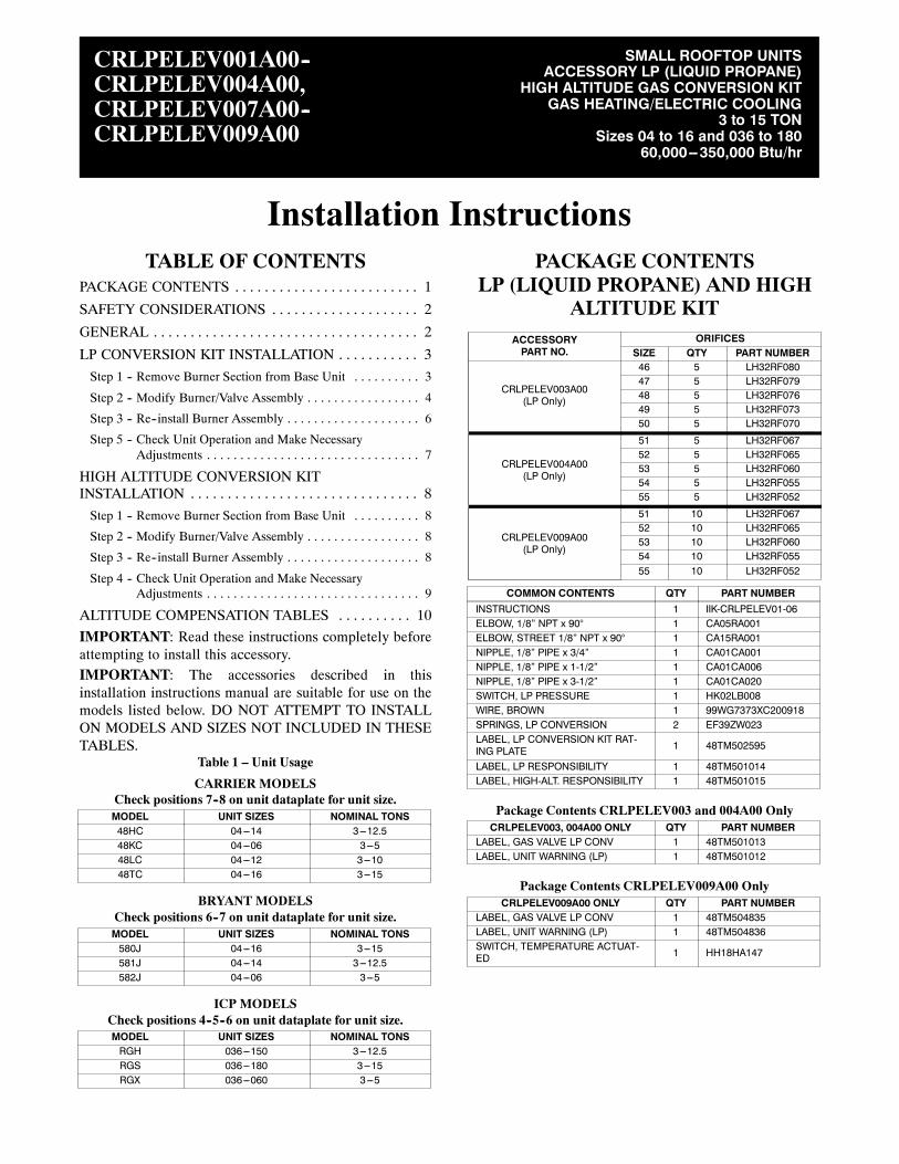
GENERALThese models are shipped from the factory equipped tooperate with natural gas at elevations up to 2000 ft(610 m). The units must be modified if installed atelevations above 2000 ft (610 m), or if operated withliquid propane.For installations in Canada, the input rating must bederated by 10% for altitudes of 2000 ft (610 m) to 4500 ft(1372 m) above sea level.Seven different gas conversion kits are available, asshown in Package Contents table. Each kit contains aparticular range of orifice sizes plus other hardware andlabels necessary for converting the unit. Refer to Table2–5 to determine the recommended orifice size based onthe nominal heat size, fuel type, and elevation. Knowingthis orifice size, it is possible to select the proper KitAccessory Part Number from Package Contents table.
IMPORTANT: If Low NOx units are converted to LPgas, the Low NOx baffle must be removed. (See Fig. 1.)The unit will no longer be classified as Low NOx units.For installation simplicity, it is suggested that the LPConversion Kit be used with standard units only.
FIRE, EXPLOSION, CARBON MONOXIDEPOISONING, PROPERTY DAMAGE HAZARDFailure to follow this warning could result in personalinjury, death or property damage.
This conversion kit shall be installed by a qualifiedservice agency in accordance with the manufacturer’sinstructions and all applicable codes and requirementsof the authority having jurisdiction. The qualifiedservice agency is responsible for the properinstallation of this kit. The installation is not properand complete until the operation of the convertedfurnace is checked as specified in the manufacturer’sinstructions supplied in the kit.
! WARNING
CRLPELEV
3
FEU, EXPLOSION, EMPOISONNEMENT PARCARBON DE MONOXYDE, RISQUE DEDOMMAGE ÀLAPROPRIÉTÉLa négligeance de suivre l’avis suivant, peut causerdes blessures personnelles, la mort ou du dommage àla propriété.
Cette trousse de conversion doit être installée par unEntrepreneur qualifié, selon les instructions dufabricant et doit se conformer à toutes les exigences ettout les codes pertinents de l’autorité compétente.L’Entrepreneur qualifié est responsable, et doits’assurer de bien suivre les instructions dans cet avis.L’installation sera considèrèè conforme et rencontrantles spécifications et instructions du fabriquant qui sontinclus dans la trousse, seulement aprés vérification del’opération de la fournaise convertie.
! AVERTISSEMENT
Firing Tube
NOx Baffle
C00151
Fig. 1 -- Low NOx Baffle Location
EXPLOSION, PERSONAL INJURY HAZARDFailure to follow this warning could result in personalinjury or death.
Two--Stage Gas Valve -- Unit is designed to operate atsee Table NO TAG of manifold pressure with propanegas.
Single--Stage Gas Valve -- Unit is designed to operateat a 10.0--in. wc of manifold pressure with propane gas.
! WARNING
FIRE, EXPLOSION, ELECTRICAL HAZARDFailure to follow this warning could result in personalinjury, death or property damage.
Gas supply MUST be shut off before disconnectingelectrical power and proceeding with conversion.
! WARNING
ELECTRICAL SHOCK HAZARDFailure to follow this warning could result in personalinjury or death.
Before installing or servicing system, always turn offmain power to system. There may be more than onedisconnect switch. Tag disconnect switch with suitablewarning label.
! WARNING
Check that your unit model number agrees with Table 1.
LP CONVERSION KITINSTALLATION
NOTE: Before starting installation of this accessory,check your unit’s dataplate for model and size andcompare to the Unit Usage table on page 1. If your unit’ssize designation exceeds the largest size listed for yourmodel, STOP. This accessory is not for use on your unit.Consult with your sales office for the correct accessorypart number for use on your unit.
Step 1 — Remove Burner Section from BaseUnit
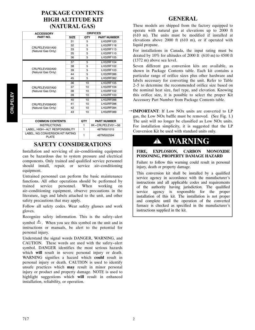
1. Shut off main gas supply to unit.2. Shut off power to unit and install lockout tag.3. Remove burner access panel. (See Fig. 2.)
BurnerAccessPanel
GasValve
Attach WARNINGLabel Here
Attach ResponsibilityLabel Here(Inside Panel)
Attach Conversion KitRating Plate Label Here(Inside Panel)
C09434
Fig. 2 -- Typical Base Unit
4. Slide out burner section side panel.5. Disconnect gas piping at unit gas valve.6. Remove wires connected to gas valve. Mark eachwire.
7. Remove igniter and sensor wires. Mark each wire.8. For units with burner sections as shown in Fig. 3,remove the 2 screws that attach the burner rack tothe vestibule plate. For units with burner sectionsas shown in Fig. 5 remove the 4 screws that hold themanifold to the sheet metal brackets.
CRLPELEV
4
Burner RackMounting Screws(1 of 2 shown)
Attach Gas ValveConverstion to LPLabel here
Gas ValveManualShut-off
GasValveBracket
Manifold Pressure Tap
C08237
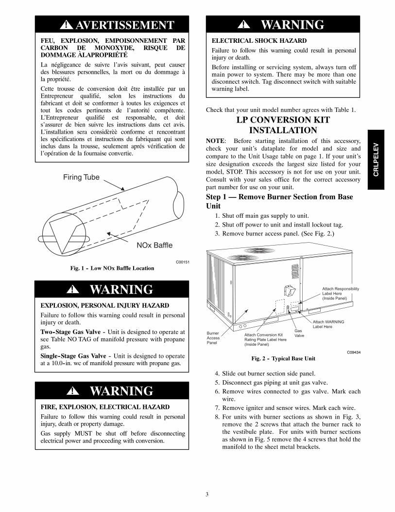
Fig. 3 -- Gas Section Details (Small Chassis Shown)
9. Remove the gas valve bracket.10. Slide the burner rack or manifold out of the unit.11. For small chassis units only----inspect the inlet of the
heat exchanger tubes for presence of V--shaped NOxbaffles. (See Fig. 1.) If baffles are present, they mustbe removed prior to converting unit for propane gas.Using needle nose pliers, remove NOx baffles.Squeeze sides of the baffle, if necessary, to removefrom the heat exchanger tubes.
IMPORTANT: If this unit will be converted back tonatural gas at a later time, these baffles should be retainedfor reuse. Otherwise the baffles may be discarded.
Step 2 — Modify Burner/Valve Assembly1. Separate burners from frame by removing screws.2. Remove existing gas orifices. Install the new ori-fices from the gas conversion kit, making sure theymatch the recommended size from Table 2--5.
IMPORTANT: Never use Teflon tape to seal gas orificethreads because peeling tape can plug the orifice.
3. Remount burners to support frame.
IMPORTANT: The burners should be positioned in thesame order as shipped from the factory. The crossoverflame region of the outermost burners are pinched off toprevent excessive gas flow from the sides of the burnerassembly. If the pinched crossovers are installed betweentwo burners, the flame will not ignite properly.
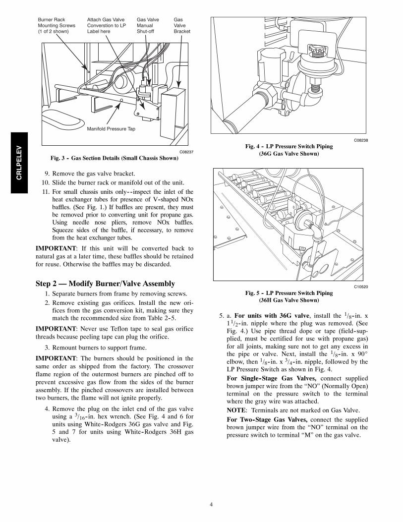
4. Remove the plug on the inlet end of the gas valveusing a 3/16--in. hex wrench. (See Fig. 4 and 6 forunits using White--Rodgers 36G gas valve and Fig.5 and 7 for units using White--Rodgers 36H gasvalve).
C08238
Fig. 4 -- LP Pressure Switch Piping(36G Gas Valve Shown)
C10520
Fig. 5 -- LP Pressure Switch Piping(36H Gas Valve Shown)
5. a. For units with 36G valve, install the 1/8--in. x11/2--in. nipple where the plug was removed. (SeeFig. 4.) Use pipe thread dope or tape (field--sup-plied, must be certified for use with propane gas)for all joints, making sure not to get any excess inthe pipe or valve. Next, install the 1/8--in. x 90_elbow, then 1/8--in. x 3/4--in. nipple, followed by theLP Pressure Switch as shown in Fig. 4.For Single--Stage Gas Valves, connect suppliedbrown jumper wire from the “NO” (Normally Open)terminal on the pressure switch to the terminalwhere the gray wire was attached.NOTE: Terminals are not marked on Gas Valve.For Two--Stage Gas Valves, connect the suppliedbrown jumper wire from the “NO” terminal on thepressure switch to terminal “M” on the gas valve.
CRLPELEV
5
Two-Stage 36G Valve Single-Stage 36G Valve
PLASTICADJUSTSCREW
REGULATORCOVER SCREW
REGULATOR SPRING(PROPANE - WHITENATURAL - SILVER)
GAS PRESSUREREGULATORADJUSTMENT
MANIFOLDPRESSURE TAP
ON/OFF SWITCH
ON/OFF SWITCH
1/2˝ NPT INLET1/2˝ NPT INLET
INLETPRESSURE TAP
1/2˝ NPT OUTLET
REGULATOR COVER SCREW
PLASTIC ADJUST SCREW
REGULATOR SPRING(Propane - White, Natural - Silver)HIGH STAGE GASPRESSURE REGULATORADJUSTMENT
LOW STAGEGAS PRESSUREREGULATOR ADJUSTMENT
MANIFOLDPRESSURE TAP
1/2˝ NPT OUTLET
INLETPRESSURE TAP
C10521
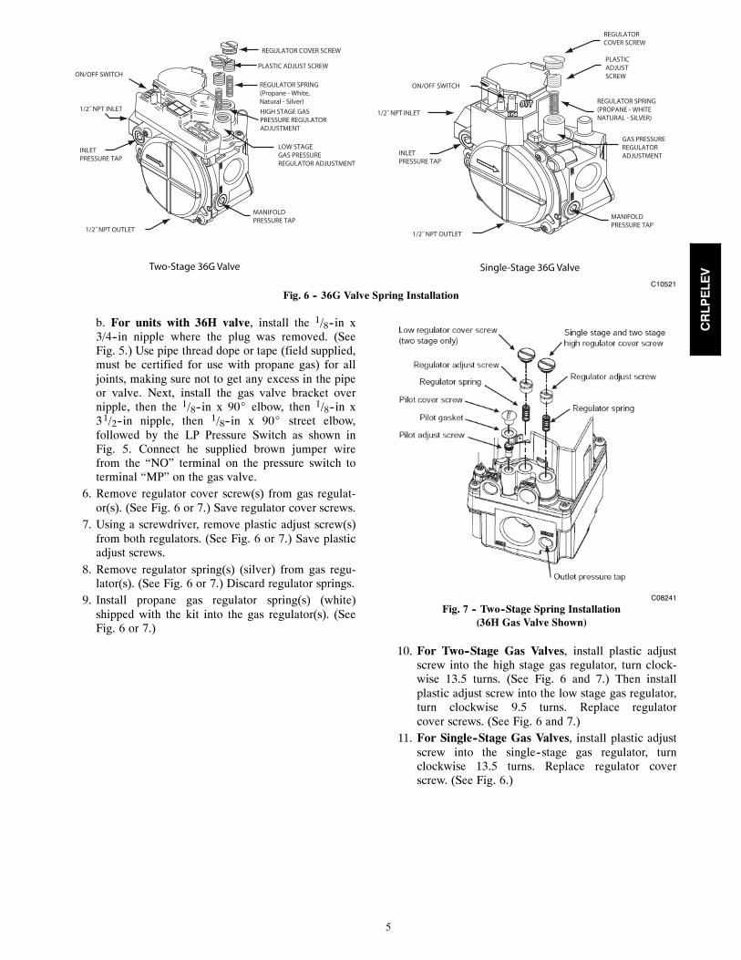
Fig. 6 -- 36G Valve Spring Installation
b. For units with 36H valve, install the 1/8--in x3/4--in nipple where the plug was removed. (SeeFig. 5.) Use pipe thread dope or tape (field supplied,must be certified for use with propane gas) for alljoints, making sure not to get any excess in the pipeor valve. Next, install the gas valve bracket overnipple, then the 1/8--in x 90_ elbow, then 1/8--in x31/2--in nipple, then 1/8--in x 90_ street elbow,followed by the LP Pressure Switch as shown inFig. 5. Connect he supplied brown jumper wirefrom the “NO” terminal on the pressure switch toterminal “MP” on the gas valve.
6. Remove regulator cover screw(s) from gas regulat-or(s). (See Fig. 6 or 7.) Save regulator cover screws.
7. Using a screwdriver, remove plastic adjust screw(s)from both regulators. (See Fig. 6 or 7.) Save plasticadjust screws.
8. Remove regulator spring(s) (silver) from gas regu-lator(s). (See Fig. 6 or 7.) Discard regulator springs.
9. Install propane gas regulator spring(s) (white)shipped with the kit into the gas regulator(s). (SeeFig. 6 or 7.)
C08241
Fig. 7 -- Two--Stage Spring Installation(36H Gas Valve Shown)
10. For Two--Stage Gas Valves, install plastic adjustscrew into the high stage gas regulator, turn clock-wise 13.5 turns. (See Fig. 6 and 7.) Then installplastic adjust screw into the low stage gas regulator,turn clockwise 9.5 turns. Replace regulatorcover screws. (See Fig. 6 and 7.)
11. For Single--Stage Gas Valves, install plastic adjustscrew into the single--stage gas regulator, turnclockwise 13.5 turns. Replace regulator coverscrew. (See Fig. 6.)
CRLPELEV
6
Step 3 — Re--install Burner Assembly1. Slide the burner rack into the unit.2. Attach burner rack or manifold with previously re-moved screws.
3. Fasten gas valve bracket with 2 screws in base.4. Reconnect the igniter and sensor wires.5. Reconnect the wires to the gas valve, except for thegrey wire. Connect the grey wire to to terminal “C”on the pressure switch.
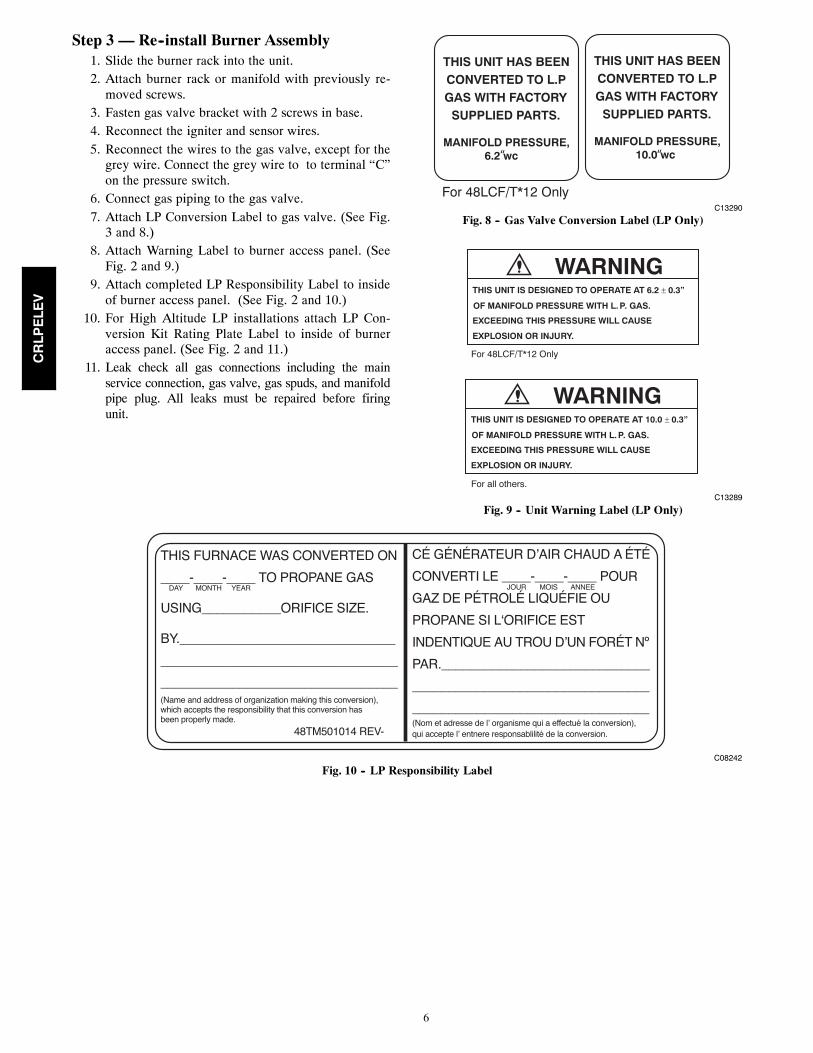
6. Connect gas piping to the gas valve.7. Attach LP Conversion Label to gas valve. (See Fig.3 and 8.)
8. Attach Warning Label to burner access panel. (SeeFig. 2 and 9.)
9. Attach completed LP Responsibility Label to insideof burner access panel. (See Fig. 2 and 10.)
10. For High Altitude LP installations attach LP Con-version Kit Rating Plate Label to inside of burneraccess panel. (See Fig. 2 and 11.)
11. Leak check all gas connections including the mainservice connection, gas valve, gas spuds, and manifoldpipe plug. All leaks must be repaired before firingunit.
THIS UNIT HAS BEENCONVERTED TO L.PGAS WITH FACTORY
SUPPLIED PARTS.
MANIFOLD PRESSURE,10.0 wc“
THIS UNIT HAS BEENCONVERTED TO L.PGAS WITH FACTORY
SUPPLIED PARTS.
MANIFOLD PRESSURE,6.2 wc“
For 48LCF/T*12 OnlyC13290
Fig. 8 -- Gas Valve Conversion Label (LP Only)
WARNINGTHIS UNIT IS DESIGNED TO OPERATE AT 10.0 ± 0.3”
OF MANIFOLD PRESSURE WITH L. P. GAS.
EXCEEDING THIS PRESSURE WILL CAUSE
EXPLOSION OR INJURY.
WARNINGTHIS UNIT IS DESIGNED TO OPERATE AT 6.2 ± 0.3”
OF MANIFOLD PRESSURE WITH L. P. GAS.
EXCEEDING THIS PRESSURE WILL CAUSE
EXPLOSION OR INJURY.
For 48LCF/T*12 Only
For all others.C13289
Fig. 9 -- Unit Warning Label (LP Only)
C08242
Fig. 10 -- LP Responsibility Label
CRLPELEV
7
FIRE AND EXPLOSION HAZARDFailure to follow this warning could result in personalinjury and/or property damage.
Never test for gas leaks with an open flame. Use acommercially available soap solution made specificallyfor the detection of leaks to check all connections.
! WARNING
The newly installed low gas pressure switch is a safetydevice used to guard against adverse burner operatingcharacteristics that can result from low gas supplypressure. Switch opens at not less than 7.2--in. wc andcloses at not greater than 10.2--in. wc.This switch also prevents operation when the propane tanklevel is low which can result in gas with a highconcentration of impurities, additives, and residues thathave settled to the bottom of the tank. Operation underthese conditions can cause harm to the heat exchangersystem. This normally open switch closes when gas issupplied to gas valve under normal LP operation pressureof 11.0 to 13.0--in.wc. The closed switch completes thecontrol circuit. Should an interruption or reduction in gassupply occur, the gas pressure at switch drops below lowgas pressure switch setting, and switch opens. Anyinterruption in control circuit (in which low gas pressureswitch is wired) quickly closes gas valve and stops gasflow to burners.
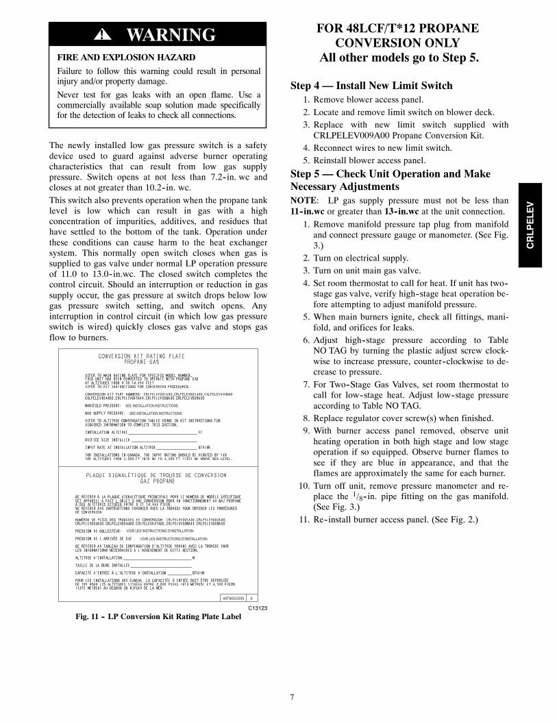
SEE INSTALLATION INSTRUCTIONS
SEE INSTALLATION INSTRUCTIONS
VOIR LES INSTRUCTIONS D'INSTALLATION
VOIR LES INSTRUCTIONS D'INSTALLATION
48TM502595 A
C13123
Fig. 11 -- LP Conversion Kit Rating Plate Label
FOR 48LCF/T*12 PROPANECONVERSION ONLY
All other models go to Step 5.
Step 4 — Install New Limit Switch1. Remove blower access panel.2. Locate and remove limit switch on blower deck.3. Replace with new limit switch supplied withCRLPELEV009A00 Propane Conversion Kit.
4. Reconnect wires to new limit switch.5. Reinstall blower access panel.
Step 5 — Check Unit Operation and MakeNecessary AdjustmentsNOTE: LP gas supply pressure must not be less than11--in.wc or greater than 13--in.wc at the unit connection.
1. Remove manifold pressure tap plug from manifoldand connect pressure gauge or manometer. (See Fig.3.)
2. Turn on electrical supply.3. Turn on unit main gas valve.4. Set room thermostat to call for heat. If unit has two--stage gas valve, verify high--stage heat operation be-fore attempting to adjust manifold pressure.
5. When main burners ignite, check all fittings, mani-fold, and orifices for leaks.
6. Adjust high--stage pressure according to TableNO TAG by turning the plastic adjust screw clock-wise to increase pressure, counter--clockwise to de-crease to pressure.
7. For Two--Stage Gas Valves, set room thermostat tocall for low--stage heat. Adjust low--stage pressureaccording to Table NO TAG.
8. Replace regulator cover screw(s) when finished.9. With burner access panel removed, observe unitheating operation in both high stage and low stageoperation if so equipped. Observe burner flames tosee if they are blue in appearance, and that theflames are approximately the same for each burner.
10. Turn off unit, remove pressure manometer and re-place the 1/8--in. pipe fitting on the gas manifold.(See Fig. 3.)
11. Re--install burner access panel. (See Fig. 2.)CRLPELEV
8
HIGH ALTITUDE CONVERSIONKIT INSTALLATION
FIRE, EXPLOSION AND ELECTRICAL SHOCKHAZARDFailure to follow this warning could result in personalinjury, death and/or property damage.
Gas supply MUST be shut off before disconnectingelectrical power and proceeding with conversion.
! WARNING
Step 1 — Remove Burner Section from BaseUnit
1. Shut off main gas supply to unit.2. Shut off power to unit and install lockout tag.3. Remove burner access panel.4. Slide out burner section side panel.5. Disconnect gas piping at unit gas valve.6. Remove wires connected to gas valve. Mark eachwire.
7. Remove igniter and sensor wires. Mark each wire.8. Remove the 2 screws that attach the burner rack tothe vestibule plate.
9. Remove the gas valve bracket.10. Slide the burner rack out of the unit. (See Fig. 3.)
Step 2 — Modify Burner/Valve Assembly1. Separate burners from frame by removing screws.2. Remove existing gas orifices. Install the new ori-fices from the gas conversion kit, making sure theymatch the recommended size from Table 2--5.
IMPORTANT: Never use Teflon tape to seal gas orificethreads because peeling tape can plug the orifice.
3. Remount burners to support frame.
IMPORTANT: The burners should be positioned in thesame order as shipped from the factory. The crossoverflame region of the outermost burners are pinched off toprevent excessive gas flow from the sides of the burner
assembly. If the pinched crossovers are installed betweentwo burners, the flame will not ignite properly.
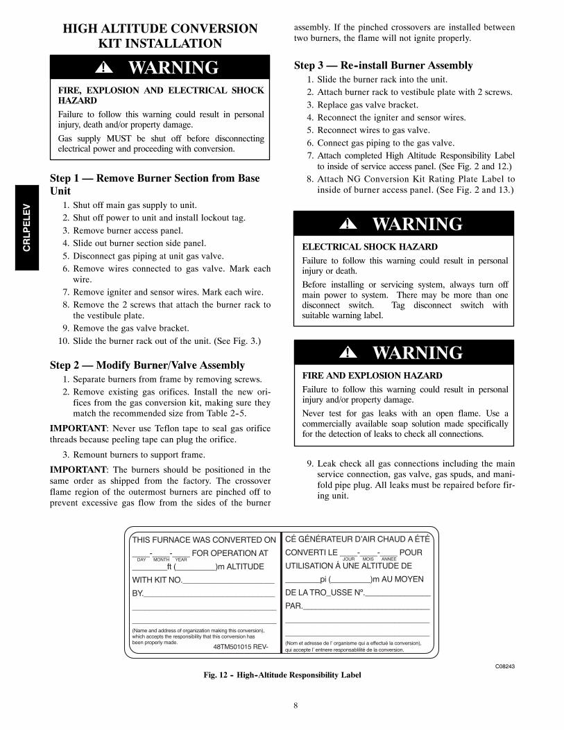
Step 3 — Re--install Burner Assembly1. Slide the burner rack into the unit.2. Attach burner rack to vestibule plate with 2 screws.3. Replace gas valve bracket.4. Reconnect the igniter and sensor wires.5. Reconnect wires to gas valve.6. Connect gas piping to the gas valve.7. Attach completed High Altitude Responsibility Labelto inside of service access panel. (See Fig. 2 and 12.)
8. Attach NG Conversion Kit Rating Plate Label toinside of burner access panel. (See Fig. 2 and 13.)
ELECTRICAL SHOCK HAZARDFailure to follow this warning could result in personalinjury or death.
Before installing or servicing system, always turn offmain power to system. There may be more than onedisconnect switch. Tag disconnect switch withsuitable warning label.
! WARNING
FIRE AND EXPLOSION HAZARDFailure to follow this warning could result in personalinjury and/or property damage.
Never test for gas leaks with an open flame. Use acommercially available soap solution made specificallyfor the detection of leaks to check all connections.
! WARNING
9. Leak check all gas connections including the mainservice connection, gas valve, gas spuds, and mani-fold pipe plug. All leaks must be repaired before fir-ing unit.
C08243
Fig. 12 -- High--Altitude Responsibility Label
CRLPELEV
9
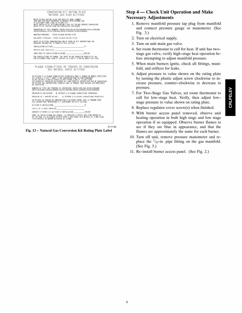
C11145
Fig. 13 -- Natural Gas Conversion Kit Rating Plate Label
Step 4 — Check Unit Operation and MakeNecessary Adjustments
1. Remove manifold pressure tap plug from manifoldand connect pressure gauge or manometer. (SeeFig. 3.)
2. Turn on electrical supply.3. Turn on unit main gas valve.4. Set room thermostat to call for heat. If unit has two--stage gas valve, verify high--stage heat operation be-fore attempting to adjust manifold pressure.
5. When main burners ignite, check all fittings, mani-fold, and orifices for leaks.
6. Adjust pressure to value shown on the rating plateby turning the plastic adjust screw clockwise to in-crease pressure, counter--clockwise to decrease topressure.
7. For Two--Stage Gas Valves, set room thermostat tocall for low--stage heat. Verify, then adjust low--stage pressure to value shown on rating plate.
8. Replace regulator cover screw(s) when finished.9. With burner access panel removed, observe unitheating operation in both high stage and low stageoperation if so equipped. Observe burner flames tosee if they are blue in appearance, and that theflames are approximately the same for each burner.
10. Turn off unit, remove pressure manometer and re-place the 1/8--in. pipe fitting on the gas manifold.(See Fig. 3.)
11. Re--install burner access panel. (See Fig. 2.)
CRLPELEV
10
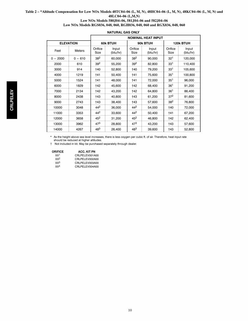
Table 2 – *Altitude Compensation for Low NOx Models 48TC04--06 (L, M, N), 48HC04--06 (L, M, N), 48KC04--06 (L, M, N) and48LC04--06 (L,M,N)
Low NOx Models 580J04--06, 581J04--06 and 582J04--06Low NOx Models RGS036, 048, 060, RGH036, 048, 060 and RGX036, 048, 060
NATURAL GAS ONLY
NOMINAL HEAT INPUT
ELEVATION 60k BTUH 90k BTUH 120k BTUH
Feet Meters OrificeSize
Input(btu/hr)
OrificeSize
Input(btu/hr)
OrificeSize
Input(btu/hr)
0 --- 2000 0 --- 610 382 60,000 382 90,000 321 120,000
2000 610 392 55,200 392 82,800 331 110,400
3000 914 †40 52,800 †40 79,200 331 105,600
4000 1219 †41 50,400 †41 75,600 351 100,800
5000 1524 †41 48,000 †41 72,000 351 96,000
6000 1829 †42 45,600 †42 68,400 361 91,200
7000 2134 †42 43,200 †42 64,800 361 86,400
8000 2438 †43 40,800 †43 61,200 372 81,600
9000 2743 †43 38,400 †43 57,600 382 76,800
10000 3048 442 36,000 442 54,000 †40 72,000
11000 3353 442 33,600 442 50,400 †41 67,200
12000 3658 452 31,200 452 46,800 †42 62,400
13000 3962 473 28,800 473 43,200 †43 57,600
14000 4267 483 26,400 483 39,600 †43 52,800
* As the height above sea level increases, there is less oxygen per cubic ft. of air. Therefore, heat input rateshould be reduced at higher altitudes.
{ Not included in kit. May be purchased separately through dealer.
ORIFICEXX1
XX2
XX3
XX4
ACC. KIT PNCRLPELEV001A00CRLPELEV002A00CRLPELEV003A00CRLPELEV004A00
CRLPELEV
11
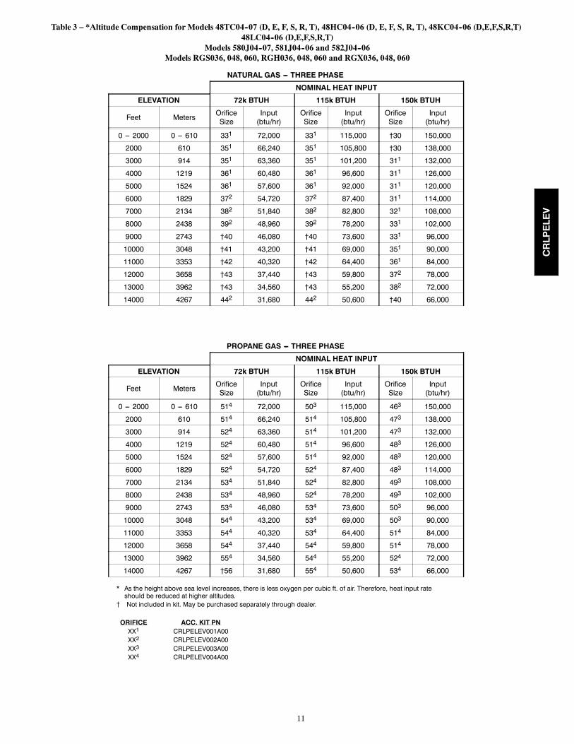
Table 3 – *Altitude Compensation for Models 48TC04--07 (D, E, F, S, R, T), 48HC04--06 (D, E, F, S, R, T), 48KC04--06 (D,E,F,S,R,T)48LC04--06 (D,E,F,S,R,T)
Models 580J04--07, 581J04--06 and 582J04--06Models RGS036, 048, 060, RGH036, 048, 060 and RGX036, 048, 060
NATURAL GAS --- THREE PHASE
NOMINAL HEAT INPUT
ELEVATION 72k BTUH 115k BTUH 150k BTUH
Feet Meters OrificeSize
Input(btu/hr)
OrificeSize
Input(btu/hr)
OrificeSize
Input(btu/hr)
0 --- 2000 0 --- 610 331 72,000 331 115,000 †30 150,000
2000 610 351 66,240 351 105,800 †30 138,000
3000 914 351 63,360 351 101,200 311 132,000
4000 1219 361 60,480 361 96,600 311 126,000
5000 1524 361 57,600 361 92,000 311 120,000
6000 1829 372 54,720 372 87,400 311 114,000
7000 2134 382 51,840 382 82,800 321 108,000
8000 2438 392 48,960 392 78,200 331 102,000
9000 2743 †40 46,080 †40 73,600 331 96,000
10000 3048 †41 43,200 †41 69,000 351 90,000
11000 3353 †42 40,320 †42 64,400 361 84,000
12000 3658 †43 37,440 †43 59,800 372 78,000
13000 3962 †43 34,560 †43 55,200 382 72,000
14000 4267 442 31,680 442 50,600 †40 66,000
PROPANE GAS --- THREE PHASE
NOMINAL HEAT INPUT
ELEVATION 72k BTUH 115k BTUH 150k BTUH
Feet Meters OrificeSize
Input(btu/hr)
OrificeSize
Input(btu/hr)
OrificeSize
Input(btu/hr)
0 --- 2000 0 --- 610 514 72,000 503 115,000 463 150,000
2000 610 514 66,240 514 105,800 473 138,000
3000 914 524 63,360 514 101,200 473 132,000
4000 1219 524 60,480 514 96,600 483 126,000
5000 1524 524 57,600 514 92,000 483 120,000
6000 1829 524 54,720 524 87,400 483 114,000
7000 2134 534 51,840 524 82,800 493 108,000
8000 2438 534 48,960 524 78,200 493 102,000
9000 2743 534 46,080 534 73,600 503 96,000
10000 3048 544 43,200 534 69,000 503 90,000
11000 3353 544 40,320 534 64,400 514 84,000
12000 3658 544 37,440 544 59,800 514 78,000
13000 3962 554 34,560 544 55,200 524 72,000
14000 4267 †56 31,680 554 50,600 534 66,000
* As the height above sea level increases, there is less oxygen per cubic ft. of air. Therefore, heat input rateshould be reduced at higher altitudes.
{ Not included in kit. May be purchased separately through dealer.
ORIFICEXX1
XX2
XX3
XX4
ACC. KIT PNCRLPELEV001A00CRLPELEV002A00CRLPELEV003A00CRLPELEV004A00
CRLPELEV
12
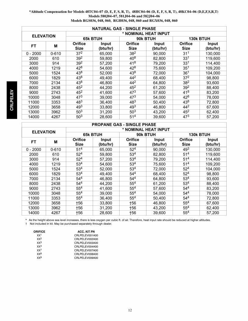
*Altitude Compensation for Models 48TC04--07 (D, E, F, S, R, T), 48HC04--06 (D, E, F, S, R, T), 48KC04--06 (D,E,F,S,R,T)Models 580J04--07, 581J04--06 and 582J04--06
Models RGS036, 048, 060, RGH036, 048, 060 and RGX036, 048, 060
NATURAL GAS - SINGLE PHASE
ELEVATION* NOMINAL HEAT INPUT
65k BTUH 90k BTUH 130k BTUH
FT MOrificeSize
Input(btu/hr)
OrificeSize
Input(btu/hr)
OrificeSize
Input(btu/hr)
0 - 2000 0-610 372 65,000 382 90,000 311 130,0002000 610 392 59,800 408 82,800 331 119,6003000 914 392 57,200 418 79,200 331 114,4004000 1219 428 54,600 428 75,600 351 109,2005000 1524 438 52,000 438 72,000 361 104,0006000 1829 438 49,400 442 68,400 372 98,8007000 2134 438 46,800 442 64,800 382 93,6008000 2438 452 44,200 452 61,200 392 88,4009000 2743 452 41,600 473 57,600 418 83,20010000 3048 473 39,000 473 54,000 428 78,00011000 3353 483 36,400 483 50,400 438 72,80012000 3658 493 33,800 493 46,800 442 67,60013000 3962 503 31,200 503 43,200 452 62,40014000 4267 503 28,600 514 39,600 473 57,200
PROPANE GAS - SINGLE PHASE
ELEVATION* NOMINAL HEAT INPUT
65k BTUH 90k BTUH 130k BTUH
FT MOrificeSize
Input(btu/hr)
OrificeSize
Input(btu/hr)
OrificeSize
Input(btu/hr)
0 - 2000 0-610 514 65,000 524 90,000 493 130,0002000 610 524 59,800 534 82,800 514 119,6003000 914 524 57,200 534 79,200 514 114,4004000 1219 534 54,600 534 75,600 514 109,2005000 1524 534 52,000 534 72,000 524 104,0006000 1829 534 49,400 544 68,400 524 98,8007000 2134 544 46,800 544 64,800 534 93,6008000 2438 544 44,200 554 61,200 534 88,4009000 2743 554 41,600 554 57,600 544 83,20010000 3048 554 39,000 554 54,000 544 78,00011000 3353 554 36,400 554 50,400 544 72,80012000 3658 †56 33,800 †56 46,800 554 67,60013000 3962 †56 31,200 †56 43,200 554 62,40014000 4267 †56 28,600 †56 39,600 554 57,200
* As the height above sea level increases, there is less oxygen per cubic ft. of air. Therefore, heat input rate should be reduced at higher altitudes.{ Not included in kit. May be purchased separately through dealer.
ORIFICEXX1
XX2
XX3
XX4
XX7
XX8
XX9
ACC. KIT PNCRLPELEV001A00CRLPELEV002A00CRLPELEV003A00CRLPELEV004A00CRLPELEV007A00CRLPELEV008A00CRLPELEV009A00
CRLPELEV
13
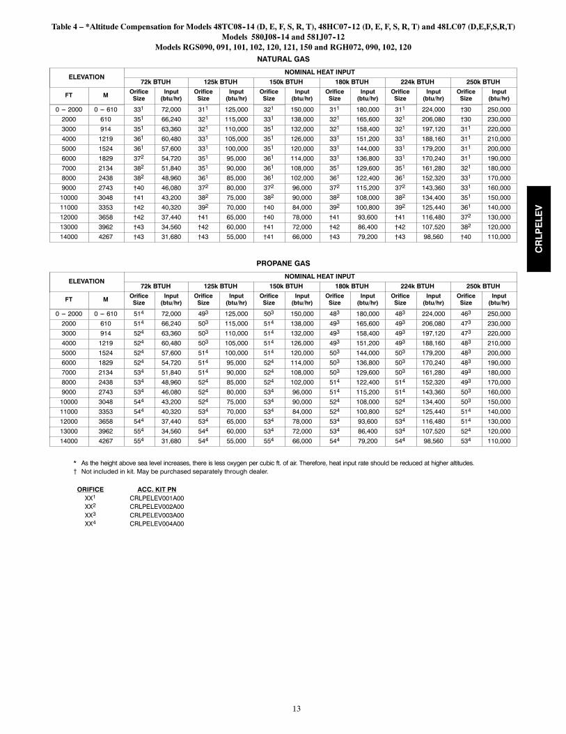
Table 4 – *Altitude Compensation for Models 48TC08--14 (D, E, F, S, R, T), 48HC07--12 (D, E, F, S, R, T) and 48LC07 (D,E,F,S,R,T)Models 580J08--14 and 581J07--12
Models RGS090, 091, 101, 102, 120, 121, 150 and RGH072, 090, 102, 120NATURAL GAS
ELEVATIONNOMINAL HEAT INPUT
72k BTUH 125k BTUH 150k BTUH 180k BTUH 224k BTUH 250k BTUH
FT M OrificeSize
Input(btu/hr)
OrificeSize
Input(btu/hr)
OrificeSize
Input(btu/hr)
OrificeSize
Input(btu/hr)
OrificeSize
Input(btu/hr)
OrificeSize
Input(btu/hr)
0 --- 2000 0 --- 610 331 72,000 311 125,000 321 150,000 311 180,000 311 224,000 †30 250,0002000 610 351 66,240 321 115,000 331 138,000 321 165,600 321 206,080 †30 230,0003000 914 351 63,360 321 110,000 351 132,000 321 158,400 321 197,120 311 220,0004000 1219 361 60,480 331 105,000 351 126,000 331 151,200 331 188,160 311 210,0005000 1524 361 57,600 331 100,000 351 120,000 331 144,000 331 179,200 311 200,0006000 1829 372 54,720 351 95,000 361 114,000 331 136,800 331 170,240 311 190,0007000 2134 382 51,840 351 90,000 361 108,000 351 129,600 351 161,280 321 180,0008000 2438 382 48,960 361 85,000 361 102,000 361 122,400 361 152,320 331 170,0009000 2743 †40 46,080 372 80,000 372 96,000 372 115,200 372 143,360 331 160,00010000 3048 †41 43,200 382 75,000 382 90,000 382 108,000 382 134,400 351 150,00011000 3353 †42 40,320 392 70,000 †40 84,000 392 100,800 392 125,440 361 140,00012000 3658 †42 37,440 †41 65,000 †40 78,000 †41 93,600 †41 116,480 372 130,00013000 3962 †43 34,560 †42 60,000 †41 72,000 †42 86,400 †42 107,520 382 120,00014000 4267 †43 31,680 †43 55,000 †41 66,000 †43 79,200 †43 98,560 †40 110,000
PROPANE GAS
ELEVATIONNOMINAL HEAT INPUT
72k BTUH 125k BTUH 150k BTUH 180k BTUH 224k BTUH 250k BTUH
FT M OrificeSize
Input(btu/hr)
OrificeSize
Input(btu/hr)
OrificeSize
Input(btu/hr)
OrificeSize
Input(btu/hr)
OrificeSize
Input(btu/hr)
OrificeSize
Input(btu/hr)
0 --- 2000 0 --- 610 514 72,000 493 125,000 503 150,000 483 180,000 483 224,000 463 250,0002000 610 514 66,240 503 115,000 514 138,000 493 165,600 493 206,080 473 230,0003000 914 524 63,360 503 110,000 514 132,000 493 158,400 493 197,120 473 220,0004000 1219 524 60,480 503 105,000 514 126,000 493 151,200 493 188,160 483 210,0005000 1524 524 57,600 514 100,000 514 120,000 503 144,000 503 179,200 483 200,0006000 1829 524 54,720 514 95,000 524 114,000 503 136,800 503 170,240 483 190,0007000 2134 534 51,840 514 90,000 524 108,000 503 129,600 503 161,280 493 180,0008000 2438 534 48,960 524 85,000 524 102,000 514 122,400 514 152,320 493 170,0009000 2743 534 46,080 524 80,000 534 96,000 514 115,200 514 143,360 503 160,00010000 3048 544 43,200 524 75,000 534 90,000 524 108,000 524 134,400 503 150,00011000 3353 544 40,320 534 70,000 534 84,000 524 100,800 524 125,440 514 140,00012000 3658 544 37,440 534 65,000 534 78,000 534 93,600 534 116,480 514 130,00013000 3962 554 34,560 544 60,000 534 72,000 534 86,400 534 107,520 524 120,00014000 4267 554 31,680 544 55,000 554 66,000 544 79,200 544 98,560 534 110,000
* As the height above sea level increases, there is less oxygen per cubic ft. of air. Therefore, heat input rate should be reduced at higher altitudes.{ Not included in kit. May be purchased separately through dealer.
ORIFICEXX1
XX2
XX3
XX4
ACC. KIT PNCRLPELEV001A00CRLPELEV002A00CRLPELEV003A00CRLPELEV004A00
CRLPELEV
14
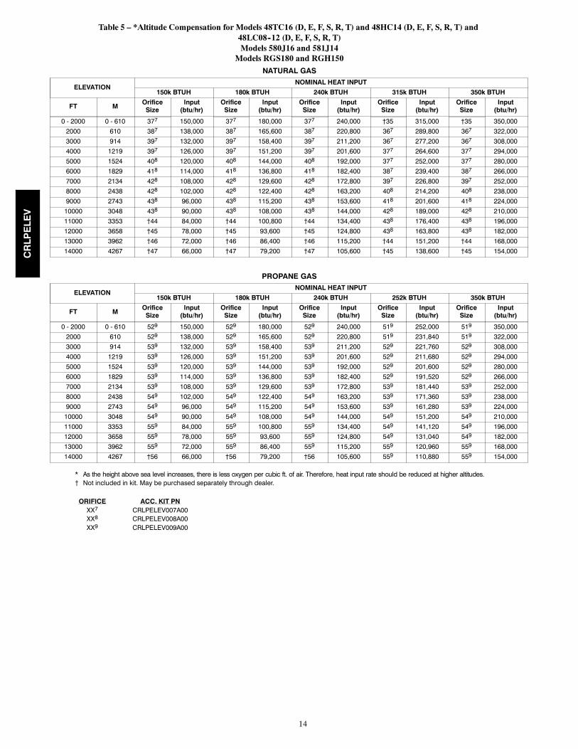
Table 5 – *Altitude Compensation for Models 48TC16 (D, E, F, S, R, T) and 48HC14 (D, E, F, S, R, T) and48LC08--12 (D, E, F, S, R, T)Models 580J16 and 581J14
Models RGS180 and RGH150NATURAL GAS
ELEVATIONNOMINAL HEAT INPUT
150k BTUH 180k BTUH 240k BTUH 315k BTUH 350k BTUH
FT M OrificeSize
Input(btu/hr)
OrificeSize
Input(btu/hr)
OrificeSize
Input(btu/hr)
OrificeSize
Input(btu/hr)
OrificeSize
Input(btu/hr)
0 - 2000 0 - 610 377 150,000 377 180,000 377 240,000 †35 315,000 †35 350,0002000 610 387 138,000 387 165,600 387 220,800 367 289,800 367 322,0003000 914 397 132,000 397 158,400 397 211,200 367 277,200 367 308,0004000 1219 397 126,000 397 151,200 397 201,600 377 264,600 377 294,0005000 1524 408 120,000 408 144,000 408 192,000 377 252,000 377 280,0006000 1829 418 114,000 418 136,800 418 182,400 387 239,400 387 266,0007000 2134 428 108,000 428 129,600 428 172,800 397 226,800 397 252,0008000 2438 428 102,000 428 122,400 428 163,200 408 214,200 408 238,0009000 2743 438 96,000 438 115,200 438 153,600 418 201,600 418 224,00010000 3048 438 90,000 438 108,000 438 144,000 428 189,000 428 210,00011000 3353 †44 84,000 †44 100,800 †44 134,400 438 176,400 438 196,00012000 3658 †45 78,000 †45 93,600 †45 124,800 438 163,800 438 182,00013000 3962 †46 72,000 †46 86,400 †46 115,200 †44 151,200 †44 168,00014000 4267 †47 66,000 †47 79,200 †47 105,600 †45 138,600 †45 154,000
PROPANE GAS
ELEVATIONNOMINAL HEAT INPUT
150k BTUH 180k BTUH 240k BTUH 252k BTUH 350k BTUH
FT M OrificeSize
Input(btu/hr)
OrificeSize
Input(btu/hr)
OrificeSize
Input(btu/hr)
OrificeSize
Input(btu/hr)
OrificeSize
Input(btu/hr)
0 - 2000 0 - 610 529 150,000 529 180,000 529 240,000 519 252,000 519 350,0002000 610 529 138,000 529 165,600 529 220,800 519 231,840 519 322,0003000 914 539 132,000 539 158,400 539 211,200 529 221,760 529 308,0004000 1219 539 126,000 539 151,200 539 201,600 529 211,680 529 294,0005000 1524 539 120,000 539 144,000 539 192,000 529 201,600 529 280,0006000 1829 539 114,000 539 136,800 539 182,400 529 191,520 529 266,0007000 2134 539 108,000 539 129,600 539 172,800 539 181,440 539 252,0008000 2438 549 102,000 549 122,400 549 163,200 539 171,360 539 238,0009000 2743 549 96,000 549 115,200 549 153,600 539 161,280 539 224,00010000 3048 549 90,000 549 108,000 549 144,000 549 151,200 549 210,00011000 3353 559 84,000 559 100,800 559 134,400 549 141,120 549 196,00012000 3658 559 78,000 559 93,600 559 124,800 549 131,040 549 182,00013000 3962 559 72,000 559 86,400 559 115,200 559 120,960 559 168,00014000 4267 †56 66,000 †56 79,200 †56 105,600 559 110,880 559 154,000
* As the height above sea level increases, there is less oxygen per cubic ft. of air. Therefore, heat input rate should be reduced at higher altitudes.{ Not included in kit. May be purchased separately through dealer.
ORIFICEXX7
XX8
XX9
ACC. KIT PNCRLPELEV007A00CRLPELEV008A00CRLPELEV009A00
CRLPELEV
15
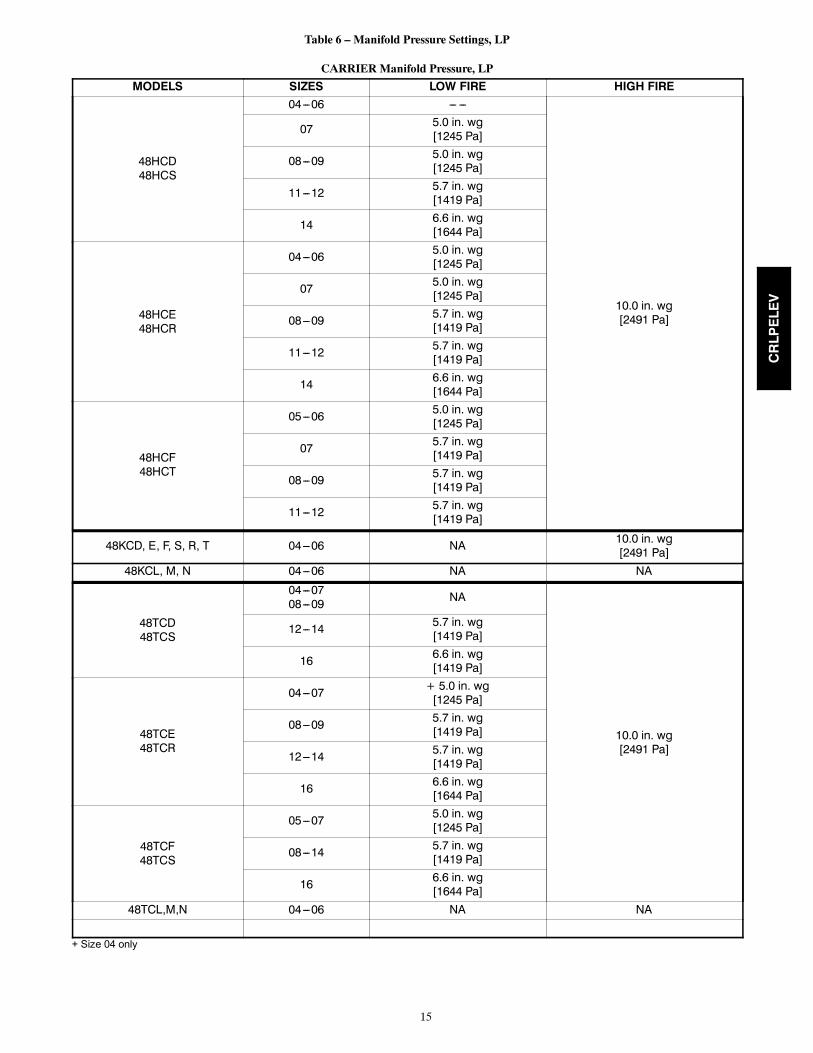
Table 6 – Manifold Pressure Settings, LP
CARRIER Manifold Pressure, LP
MODELS SIZES LOW FIRE HIGH FIRE
48HCD48HCS
04---06 --- ---
10.0 in. wg[2491 Pa]
07 5.0 in. wg[1245 Pa]
08---09 5.0 in. wg[1245 Pa]
11---12 5.7 in. wg[1419 Pa]
14 6.6 in. wg[1644 Pa]
48HCE48HCR
04---06 5.0 in. wg[1245 Pa]
07 5.0 in. wg[1245 Pa]
08---09 5.7 in. wg[1419 Pa]
11---12 5.7 in. wg[1419 Pa]
14 6.6 in. wg[1644 Pa]
48HCF48HCT
05---06 5.0 in. wg[1245 Pa]
07 5.7 in. wg[1419 Pa]
08---09 5.7 in. wg[1419 Pa]
11---12 5.7 in. wg[1419 Pa]
48KCD, E, F, S, R, T 04---06 NA 10.0 in. wg[2491 Pa]
48KCL, M, N 04---06 NA NA
48TCD48TCS
04---0708---09 NA
10.0 in. wg[2491 Pa]
12---14 5.7 in. wg[1419 Pa]
16 6.6 in. wg[1419 Pa]
48TCE48TCR
04---07 + 5.0 in. wg[1245 Pa]
08---09 5.7 in. wg[1419 Pa]
12---14 5.7 in. wg[1419 Pa]
16 6.6 in. wg[1644 Pa]
48TCF48TCS
05---07 5.0 in. wg[1245 Pa]
08---14 5.7 in. wg[1419 Pa]
16 6.6 in. wg[1644 Pa]
48TCL,M,N 04---06 NA NA
+ Size 04 only
CRLPELEV
16
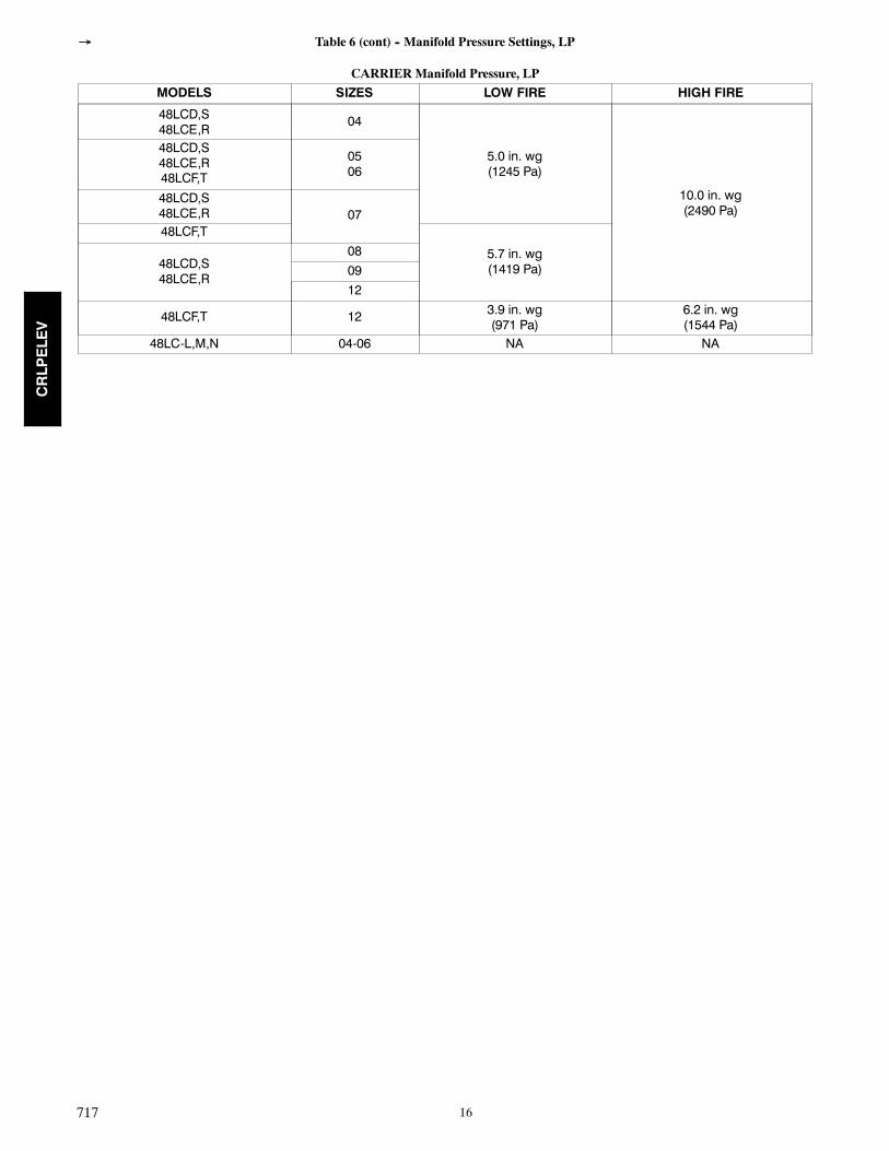
Table 6 (cont) -- Manifold Pressure Settings, LP
CARRIER Manifold Pressure, LPMODELS SIZES LOW FIRE HIGH FIRE
48LCD,S48LCE,R
04
5.0 in. wg(1245 Pa)
10.0 in. wg(2490 Pa)
48LCD,S48LCE,R48LCF,T
0506
48LCD,S48LCE,R 0748LCF,T
5.7 in. wg(1419 Pa)48LCD,S
48LCE,R
080912
48LCF,T 12 3.9 in. wg(971 Pa)
6.2 in. wg(1544 Pa)
48LC-L,M,N 04-06 NA NA
717
CRLPELEV
17
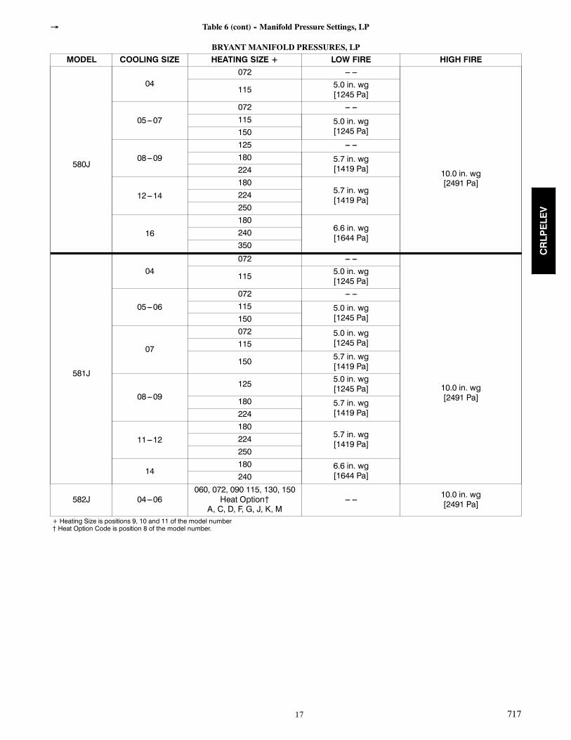
Table 6 (cont) -- Manifold Pressure Settings, LP
BRYANT MANIFOLD PRESSURES, LPMODEL COOLING SIZE HEATING SIZE + LOW FIRE HIGH FIRE
580J
04072 --- ---
10.0 in. wg[2491 Pa]
115 5.0 in. wg[1245 Pa]
05---07
072 --- ---115 5.0 in. wg
[1245 Pa]150
08---09
125 --- ---180 5.7 in. wg
[1419 Pa]224
12---14
1805.7 in. wg[1419 Pa]224
250
16
1806.6 in. wg[1644 Pa]240
350
581J
04072 --- ---
10.0 in. wg[2491 Pa]
115 5.0 in. wg[1245 Pa]
05---06
072 --- ---115 5.0 in. wg
[1245 Pa]150
07
072 5.0 in. wg[1245 Pa]115
150 5.7 in. wg[1419 Pa]
08---09125 5.0 in. wg
[1245 Pa]180 5.7 in. wg
[1419 Pa]224
11---12
1805.7 in. wg[1419 Pa]224
250
14180 6.6 in. wg
[1644 Pa]240
582J 04---06060, 072, 090 115, 130, 150
Heat Option{A, C, D, F, G, J, K, M
--- --- 10.0 in. wg[2491 Pa]
+ Heating Size is positions 9, 10 and 11 of the model number{ Heat Option Code is position 8 of the model number.
717
CRLPELEV
18
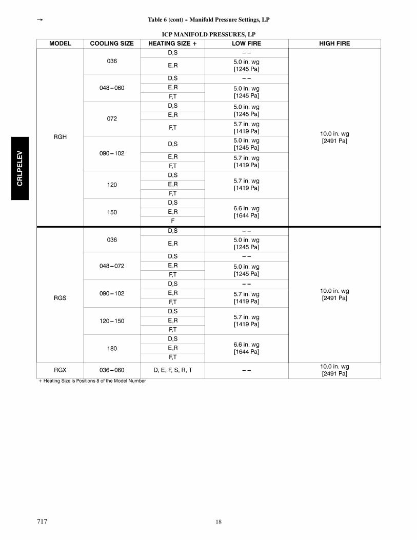
Table 6 (cont) -- Manifold Pressure Settings, LP
ICP MANIFOLD PRESSURES, LPMODEL COOLING SIZE HEATING SIZE + LOW FIRE HIGH FIRE
RGH
036D,S --- ---
10.0 in. wg[2491 Pa]
E,R 5.0 in. wg[1245 Pa]
048---060
D,S --- ---E,R 5.0 in. wg
[1245 Pa]F,T
072
D,S 5.0 in. wg[1245 Pa]E,R
F,T 5.7 in. wg[1419 Pa]
090---102D,S 5.0 in. wg
[1245 Pa]E,R 5.7 in. wg
[1419 Pa]F,T
120
D,S5.7 in. wg[1419 Pa]E,R
F,T
150
D,S6.6 in. wg[1644 Pa]E,R
F
RGS
036D,S --- ---
10.0 in. wg[2491 Pa]
E,R 5.0 in. wg[1245 Pa]
048---072
D,S --- ---E,R 5.0 in. wg
[1245 Pa]F,T
090---102
D,S --- ---E,R 5.7 in. wg
[1419 Pa]F,T
120---150
D,S5.7 in. wg[1419 Pa]E,R
F,T
180
D,S6.6 in. wg[1644 Pa]E,R
F,T
RGX 036---060 D, E, F, S, R, T --- --- 10.0 in. wg[2491 Pa]
+ Heating Size is Positions 8 of the Model Number
717
CRLPELEV

19
CRLPELEV

20
Copyright 2014 CAC / BDP D 7310 W. Morris St. D Indianapolis, IN 46231 717 Edition Date: 09/14
Manufacturer reserves the right to change, at any time, specifications and designs without notice and without obligations.
Catalog No: IIK---CRLPELEV01---06
Replaces: IIK---CRLPELEV01---05
CRLPELEV