Embed Size (px)
Citation preview

September 2017 www.tubeliteinc.com Page 13056 Walker Ridge Dr. NW, Suite G ● Walker, MI 49544 ● 800-866-2227
INSTALLATION INSTRUCTIONS400 SERIES
BLAST RESISTANT CURTAIN WALL

400 Curtain Wall Installation Instructions
Page 2 www.tubeliteinc.com September 2017
LEADERS IN ECO-EFFICIENT STOREFRONTCURTAIN WALL AND ENTRANCE SYSTEMS
BLANK

September 2017 www.tubeliteinc.com Page 3
400 Curtain Wall Installation Instructions
LEADERS IN ECO-EFFICIENT STOREFRONTCURTAIN WALL AND ENTRANCE SYSTEMS
GENERAL CONSTRUCTION NOTES .................................................................................................. 4-5
QUICK REFERENCE CHECKLIST ......................................................................................................... 5
PARTS LIST ................................................................................................................................ 6-8
ELEVATION TYPES and DETAILS .................................................................................................... 9-10
FRAME FABRICATION Step 1 Determine Frame Size ..............................................................................................11 Step 2 Cut Material to Length ............................................................................................. 12 Step 3 Drill Verticals for Shear Blocks ................................................................................. 13 Step 4 Drill Horizontals for Shear Block Attachment ........................................................... 14 Step 5 Fabricate Pressure Bars .......................................................................................... 15 Step 6 Fabricate Weep Slots in Face Covers ..................................................................... 16 Step 7 Notch Head & Sill for Anchor Clearance .................................................................. 16 Step 8 Fabricate Perimeter Anchor Clip ......................................................................... 17-18 Step 9 Install Steel Reinforcement as Required ................................................................. 19 Step 10 Fasten Shear Clip to Vertical ................................................................................... 20 Step 11 Install Head and Sill ‘F’ and ‘T’ Anchors ................................................................... 21 FRAME INSTALLATION Step 12 Installing Vertical Mullions ........................................................................................ 22 Step 13 Attach Horizontals to Shear Blocks .................................................................... 23-24 Step 14 Install Water Dams................................................................................................... 25 Step 15 Apply Perimeter Seal to Installation .................................................................... 25-26
GLAZING Step 16 Glazing Preparation ................................................................................................. 27 Step 17 Installing Gaskets and Spacers .......................................................................... 27-28 Step 18 Installing Glass ................................................................................................... 28-30 Step 19 Install Pressure Plates and Face Covers ............................................................ 31-35
ENTRANCE FRAMING ..................................................................................................................... 36-37
REGLAZING ................................................................................................................................. 38
TABLE OF CONTENTS

400 Curtain Wall Installation Instructions
Page 4 www.tubeliteinc.com September 2017
LEADERS IN ECO-EFFICIENT STOREFRONTCURTAIN WALL AND ENTRANCE SYSTEMS
1. These instructions cover typical product application, fabrication, installation and standard conditions and are general in nature. They provide useful guidelines, but the final shop drawings may include additional details specific to the project. Any conflict or discrepancies must be clarified prior to execution.
2. Materials stored at the job site must be kept in a safe place protected from possible damage by other trades. Stack with adequate separation so materials will not rub together and store off the ground. Cardboard or paper wrapped materials must be kept dry. Check arriving materials for quantity and keep a record of where various materials are stored.
3. All field welding must be done in accordance with AISC guidelines. All aluminum and glass should be shielded from field welding to avoid damage from weld splatter. Results will be unsightly and may be structurally unsound. Advise general contractor and other trades accordingly.
4. Coordinate protection of installed work with general contractor and/or other trades.
5. Coordinate sequence of other trades which affect framing installation with the general contractor (e.g. fire proofing, back up walls, partitions, ceilings, mechanical ducts, HVAC, etc.).
6. General contractor should furnish and guarantee bench marks, offset lines and opening dimensions. These items should be checked for accuracy before proceeding with erection. Make certain that all adjacent substrate construction is in accordance with the contract documents and/or approved shop drawings. If not, notify the general contractor in writing before proceeding with installation because this could constitute acceptance of adjacent substrate construction by others.
7. Isolate all aluminum to be placed directly in contact with masonry or other incompatible materials with a heavy coat of zinc chromate or bituminous paint. Fasteners attaching framing to building structure are typically not provided by Tubelite.
8. Sealant selection is the responsibility of the erector, installer and/or glazing contractor and must be approved by the sealant manufacturer with regard to application and compatibility for its intended use. All sealants must be used in strict accordance with the manufacturer’s instructions and applied only by trained personnel to surfaces that have been properly prepared.
9. Sealant must be compatible with all materials with which they have contact, including other sealant surfaces. Consult the sealant manufacturer for recommendations relative to shelf life, compatibility, cleaning of substrate, priming, tooling adhesion, etc. Recommend sealant manufacturer perform adhesion “pull test” at “wet” glazing for quality assurance.
10. Drainage gutters and weep holes must be kept clean at all times. Tubelite will not accept responsibility for improper drainage as a result of clogged gutters and weep holes.
11. This product requires clearances at the head, sill and jambs to allow for thermal expansion and contraction as well as construction tolerances. Refer to final distribution drawings for joint sizes. Joints smaller than 1/4” may be subject to failure. Consult the sealant manufacturer for proper sizing of joints.
12. All framing members, entrances and other materials are to be installed plumb, level and true with regard to established bench marks, column center lines or other working points established by the general contractor and checked by the erector, installer and/or glazing contractor.
13. After sealant is set and a representative amount of the wall has been glazed (500 square feet or more), run a water hose test to check installation. On large projects, a hose test should be repeated during glazing operation. This testing should be conducted in accordance with AAMA 501.2 specifications.
14. Cleaning of exposed aluminum surfaces should be done per AAMA recommendations. 15. Care must be taken when assembling aluminum framing components. Over tightening any fastener may cause stripping or fastener failure. Tubelite recommends the use of drill motors with clutches engaged to provide satisfactory tightening of the screw while preventing over torque. The use of impact drill motors is not recommended due to the absence of a clutch device. 16. Check www.tubeliteinc.com for any installation instruction updates.
GENERAL CONSTRUCTION NOTES

September 2017 www.tubeliteinc.com Page 5
400 Curtain Wall Installation Instructions
LEADERS IN ECO-EFFICIENT STOREFRONTCURTAIN WALL AND ENTRANCE SYSTEMS
QUICK REFERENCE CHECKLIST
1. Make sure the opening is square and the caulk joints are 1/2” minimum around the frame.
2. Ensure surfaces that will be sealed are free of contaminants that can lead to adhesion issues.
3. Check that all weeps and baffles (if required) conform to the locations and sizes called out in these instructions.
4. Butter seal ends of horizontal frame members that are joined to vertical members.
5. Water dam installation and sealing is critical. Check installation against instructions to ensure conformity.
6. Apply sealant between all corner gasket joints.
7. Glass bites must be equal on all sides.
8. Double check anchor size and location against installation instructions or approved shop drawings.
9. Ensure pressure plate fasteners are torqued to 30-40 in-lbs.
GLASS SIZE CALCULATION
Vertical and Horizontal = D.L.O. + 1¼”
GENERAL CONSTRUCTION NOTES

400 Curtain Wall Installation Instructions
Page 6 www.tubeliteinc.com September 2017
LEADERS IN ECO-EFFICIENT STOREFRONTCURTAIN WALL AND ENTRANCE SYSTEMS
TYPICAL FRAMING EXTRUSIONS
Shear Block for Horizontals
'T' Anchor for Mullions
'F' Anchor for Jambs
'U' Anchor for Door Jambs
PTB60F
PTB21B
PTB20B
PTB22
SHAPE DESCRIPTION PART No.
Captured Mullion/Horizontal
Pressure Bar
Perimeter Anchor
Glass Pocket Filler
¾" Depth Cap (Standard)
M4TB63FB
E4TB64FB
E3162FB
E3192FB
E55TB02FB
Contact www.tubeliteinc.com for additional system extrusions for enhanced project applications.

September 2017 www.tubeliteinc.com Page 7
400 Curtain Wall Installation Instructions
LEADERS IN ECO-EFFICIENT STOREFRONTCURTAIN WALL AND ENTRANCE SYSTEMS
SHAPE DESCRIPTION PART No.
P1194Temporary Glass Retainer
PTB28
P2400
PTB42
PTB93
PTB94Thermal Isolator Gasket
Glazing Gasket
Setting Block for 1" Glazing
Optional Baffle1/2" x 1" x 3"
Water Damfor Captured Glazing
Drill Fixture P2091FBA
A
A
DB
DB
P2091FBW
400CW
ACCESSORIES
400 Curtain Wall Installation Instructions
Page 8 www.tubeliteinc.com September 2017
LEADERS IN ECO-EFFICIENT STOREFRONTCURTAIN WALL AND ENTRANCE SYSTEMS
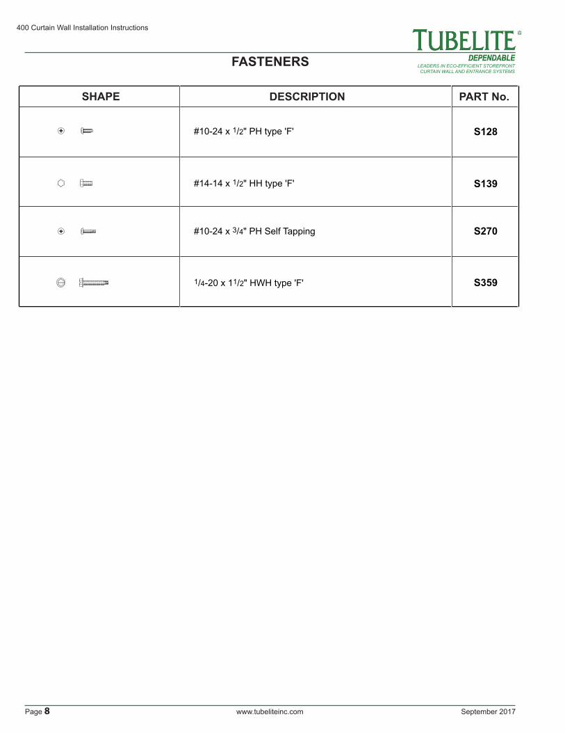
SHAPE DESCRIPTION PART No.
S359
S270
S139
S128
#14-14 x 1/2" HH type 'F'
#10-24 x 1/2" PH type 'F'
#10-24 x 3/4" PH Self Tapping
1/4-20 x 11/2" HWH type 'F'
FASTENERS

September 2017 www.tubeliteinc.com Page 9
400 Curtain Wall Installation Instructions
LEADERS IN ECO-EFFICIENT STOREFRONTCURTAIN WALL AND ENTRANCE SYSTEMS
ELEVATION and WALL SECTION
The 400 Series Blast Resistant curtain wall system is designed for single span construction.
ELEVATION
Captured
WALLSECTION
6
5
4
3
2
1
Fig. 9.1

400 Curtain Wall Installation Instructions
Page 10 www.tubeliteinc.com September 2017
LEADERS IN ECO-EFFICIENT STOREFRONTCURTAIN WALL AND ENTRANCE SYSTEMS
4 5 6Jamb JambCaptured
Mullion
2½"
FRAME WIDTH
OPENING DIMENSION
2½"2½"
½"
D.L.O.D.L.O.D.L.O.
½"
Steel reinforcement as required
DETAILS
Fig. 10.1
2½"
FRAM
E H
EIG
HT
OPE
NIN
G D
IMEN
SIO
N
2½"
2½"
½"
D.L
.O.
D.L
.O.
½"
1
2
3
Head
IntermediateHorizontal
Sill
VERTICALS
Fig. 10.2
HORIZONTALS

September 2017 www.tubeliteinc.com Page 11
400 Curtain Wall Installation Instructions
LEADERS IN ECO-EFFICIENT STOREFRONTCURTAIN WALL AND ENTRANCE SYSTEMS
FRAME FABRICATION
Step 1: Determine Frame Size
Frame WidthA. Make sure the opening is square and plumb. Measure each diagonal of the opening. SEE Fig. 11.1.B. Measure the width of the opening (Rough Opening) at the top, middle and bottom. Select the smallest of these dimensions and subtract the left and right caulk joint width per approved shop drawing (1/2” minimum caulk joint at jambs). SEE Fig. 11.2.C. Allow a larger clearance to accommodate building tolerances, an out-of-square opening, anticipated thermal expansion within the unit or as required by shop drawings.
Frame HeightD. Measure the height of the opening (Rough Opening) at several points along the entire width of the opening. Select the smallest of these dimensions and subtract 1” to allow a minimum of ½” at sill and head for shim and caulking. SEE Fig. 11.3.E. Allow a larger clearance to accommodate building tolerances, an out-of-square opening, anticipated thermal expansion within the unit or as required by shop drawings.
Measure
Dimension "A" = "B"
Measure
Measure
Mea
sure
Mea
sure
Mea
sure
Mea
sure
Mea
sure
Dimension "A" Dimension "B"
Fig. 11.1
Fig. 11.2
Fig. 11.3

400 Curtain Wall Installation Instructions
Page 12 www.tubeliteinc.com September 2017
LEADERS IN ECO-EFFICIENT STOREFRONTCURTAIN WALL AND ENTRANCE SYSTEMS
FRAME FABRICATION
D.L
.O.
D.L
.O.
FRA
ME
HE
IGH
T
2½"
2½"
2½"
D.L.O. D.L.O. D.L.O. D.L.O.
FRAME WIDTH
2½"
2½"2½"2½"
2½"
Cut extrusions to lengths as shown below:
Vertical Profiles: Vertical Mullion = Frame Height Pressure Plates = Frame Height Face Caps = Frame Height Pocket Filler at Perimeter = D.L.O. MINUS (-) 1/16” Horizontal Profiles: Head, Sill & Horizontal = D.L.O. Pressure Plates = D.L.O. MINUS (-) 3/8” Face Caps = D.L.O. MINUS (-) 1/32” Pocket Filler at Perimeter = D.L.O. MINUS (-) 1/16”
Accessories: Exterior Vertical Gasket = Pressure Plate Length PLUS (+) Allowance* Exterior Horizontal Gasket = Pressure Plate Length PLUS (+) Allowance* Interior Vertical Gasket = D.L.O. PLUS (+) 1” PLUS (+) Allowance* Interior Horizontal Gasket = D.L.O. PLUS (+) Allowance*
Fig. 12.1
Step 2: Captured Framing - Cut Materials to Size
Note: Door framing material is cut to size from the factory. In cases of door frames with transoms, the door jambs must be cut down in the field to size and head member attached per standard instructions shown within this manual.
*Allowance = 1/8” extra length per foot of D.L.O. or aluminum length

September 2017 www.tubeliteinc.com Page 13
400 Curtain Wall Installation Instructions
LEADERS IN ECO-EFFICIENT STOREFRONTCURTAIN WALL AND ENTRANCE SYSTEMS
FRAME FABRICATION
A
A
A
DB
DB
C
C
P2091FB
400CW
DR
ILL
P2091FBDrill Guide
Align with marked top of horizontal location
Drill vertical members for horizontal shear block attachment.
Shear Block
Fig. 13.2
Fig. 13.1
Fig. 13.3
Step 3: Drill Holes in Vertical Members for Shear Blocks
A. Drill .201” diameter pilot holes for #14 screws in the vertical members. Use the P2091FB drill fixture to locate these holes.
2½" 1¼
"
2½" 1¼
"
2½"
1¼"
⅞" 1⅞" 1⅞"
Mark top of horizontal location
Mullions at entrancesrun to finished floor.
Ø .221” Holes(#2 Bit)

400 Curtain Wall Installation Instructions
Page 14 www.tubeliteinc.com September 2017
LEADERS IN ECO-EFFICIENT STOREFRONTCURTAIN WALL AND ENTRANCE SYSTEMS
FRAME FABRICATION
A
A
A
D
B
D
B
CC
P2091FB400CW
DRILL
1¼"
⅝"
⅝"
1¼"
⅝"
1¼"
⅝"
⅝"
⅝"
⅜" Ø .221” Holes(#2 Bit)
Head
IntermediateHorizontal P2091FB
Drill Guide
Sill
Drill exterior flange at each end of horizontalas shown.
Fig. 14.1
Fig. 14.2
Step 4: Drill Holes in Horizontal for Attachment to Shear Blocks
A. Drill (2) .201” diameter clearance holes for #10 screws in the horizontal sections for attachment to the shear blocks. Use the P2091FB drill fixture to locate holes. See Fig. 14.1.B. Drill and countersink the bottom of each end of horizontals as shown in Fig. 14.2.
A
A
A
DB
DB
C
C
P2091FB
400CW
DR
ILL
P2091FBDrill Guide
Drill and countersink horizontal members at bottom of each end for attachment to horizontal shear block.
⅞"
⅞" ⅞"
⅞"

September 2017 www.tubeliteinc.com Page 15
400 Curtain Wall Installation Instructions
LEADERS IN ECO-EFFICIENT STOREFRONTCURTAIN WALL AND ENTRANCE SYSTEMS
FRAME FABRICATION
2"2"
6"
Fram
e H
eigh
t
6" O
.C.
2" 2"6"
7/32" Dia. weep hole
9/32" Dia. anchor hole
C L
C L
D.L.O.÷ 4 D.L.O.÷ 4
6" O.C.
D.L.O. minus ⅜"
HORIZONTAL PRESSURE BAR
VERTICAL PRESSURE BAR
6"
M4TB63FB
M4TB63FB
9/32" Dia.anchor hole
Fig. 15.1
Fig. 15.2
Step 5: Drill Weep Holes in Horizontal Pressure Plates
A. Drill 7/32” diameter weep holes in horizontal pressure plate at 1/4 points at each end. Locate the holes on the V-groove above the center line of the pressure plate.B. Pressure plates are factory punched on center for pressure plate screws. Drill additional hole(s) as required to ensure a maximum of 2” from the ends of the plates.

400 Curtain Wall Installation Instructions
Page 16 www.tubeliteinc.com September 2017
LEADERS IN ECO-EFFICIENT STOREFRONTCURTAIN WALL AND ENTRANCE SYSTEMS
FRAME FABRICATION
Wall to Wall
3"(Typ)
3"(Typ)
This side to structure
Step 7: Notch Heads and Sills to Clear Shear Clips
A. Notches must be cut in the head and sill members to provide clearance for the shear blocks. See Fig. 16.2 for proper notch size.
Fig. 16.1
Fig. 16.2
1/4 point3 /
16" 7/32" dia. weep hole
D.L.O. minus 1/16"
HORIZONTAL FACE CAP
1/4 point
E4TB64FB
Step 6: Fabricate Weep Slots in Horizontal Face Covers
A. Fabricate a 7/32” diameter weep hole on the bottom of each horizontal face cover locate at 1/4 points at each end of the cover.
September 2017 www.tubeliteinc.com Page 17
400 Curtain Wall Installation Instructions
LEADERS IN ECO-EFFICIENT STOREFRONTCURTAIN WALL AND ENTRANCE SYSTEMS
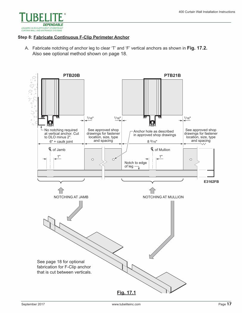
See page 18 for optional fabrication for F-Clip anchor that is cut between verticals.
Fig. 17.1
Step 8: Fabricate Continuous F-Clip Perimeter Anchor
A. Fabricate notching of anchor leg to clear ‘T’ and ‘F’ vertical anchors as shown in Fig. 17.2. Also see optional method shown on page 18.
PTB21BPTB20B
E3162FB
C L of Jamb
6" + caulk joint
NOTCHING AT JAMB NOTCHING AT MULLION
8 9/16"
See approved shopdrawings for fastenerlocation, size, type
and spacing
No notching required at vertical anchor. Cut to DLO minus 2".
Notch to edge of leg
Anchor hole as describedin approved shop drawings
See approved shopdrawings for fastenerlocation, size, type
and spacing
1"
1/16" 1/16" 1/16"
1"
C L of Mullion

400 Curtain Wall Installation Instructions
Page 18 www.tubeliteinc.com September 2017
LEADERS IN ECO-EFFICIENT STOREFRONTCURTAIN WALL AND ENTRANCE SYSTEMS
C L of mullion
PTB21BPTB20B
E3162FB
C L of Jamb
D.L.O. minus 85/8"See approved shopdrawings for fastenerlocation, size, typeand spacing.
1/16" 1/16" 1/16"
C L of Mullion
Step 8: Fabricate F-Clip Perimeter Anchor (Optional Method)
B. Cut and fabricate to fit between ‘T’ and ‘F’ vertical anchors as shown in Fig. 18.1. Vertical anchor clip runs continuous from head to sill.
Fig. 18.1

September 2017 www.tubeliteinc.com Page 19
400 Curtain Wall Installation Instructions
LEADERS IN ECO-EFFICIENT STOREFRONTCURTAIN WALL AND ENTRANCE SYSTEMS
TYPICAL APPLICATION
OPTIONAL APPLICATION
Captured Mullion
Captured Mullion
Located fasteners as directed in approved shop drawings
Located fasteners centered on horizontal location when possible. See approved shop drawing for requirments.
Drill and tap for fastener as required. Countersink for Flat Head screw.
Drill and tap for fastener as required. Countersink for Flat Head screw.
Steel reinforcement shown is for reference only.See approved shop drawing for steel requirments.
Steel reinforcement shown is for reference only.See approved shop drawing for steel requirments.
C Lof Horizontal
Fig. 19.1
Fig. 19.2
Step 9: Install Steel Reinforcement As Required
A. Refer to approved shop drawings to determine where steel reinforcing may be required.B. Steel should be installed prior to the attachment of shear blocks.C. Steel should be sized to stop short of the top and bottom of the vertical for clearance.D. Locate and prep for attachment of the steel located under the horizontal shear blocks if possible. Otherwise, steel can be secured to the vertical mullion through the tongue. Anchor the steel to the vertical using fasteners and spacing per approved shop drawings (not supplied by Tubelite).
FRAME FABRICATION

400 Curtain Wall Installation Instructions
Page 20 www.tubeliteinc.com September 2017
LEADERS IN ECO-EFFICIENT STOREFRONTCURTAIN WALL AND ENTRANCE SYSTEMS
Step 10: Fasten Shear Blocks
A. Fasten the shear blocks to horizontals using (3) S139 fasteners per clip.
NOTE: If steel reinforcement is required, it must be installed prior to shear block attachment.
S139(Typ)
Shear Block AttachmentFig. 20.1
FRAME FABRICATION
September 2017 www.tubeliteinc.com Page 21
400 Curtain Wall Installation Instructions
LEADERS IN ECO-EFFICIENT STOREFRONTCURTAIN WALL AND ENTRANCE SYSTEMS
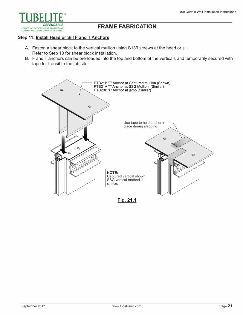
Step 11: Install Head or Sill F and T Anchors
A. Fasten a shear block to the vertical mullion using S139 screws at the head or sill. Refer to Step 10 for shear block installation.B. F and T anchors can be pre-loaded into the top and bottom of the verticals and temporarily secured with tape for transit to the job site.
Use tape to hold anchor in place during shipping.
NOTE:Captured vertical shown,SSG vertical method is similar.
PTB21B 'T' Anchor at Captured mullion (Shown)PTB21A 'T' Anchor at SSG Mullion (Similar)PTB20B 'F' Anchor at jamb (Similar)
Fig. 21.1
FRAME FABRICATION
400 Curtain Wall Installation Instructions
Page 22 www.tubeliteinc.com September 2017
LEADERS IN ECO-EFFICIENT STOREFRONTCURTAIN WALL AND ENTRANCE SYSTEMS
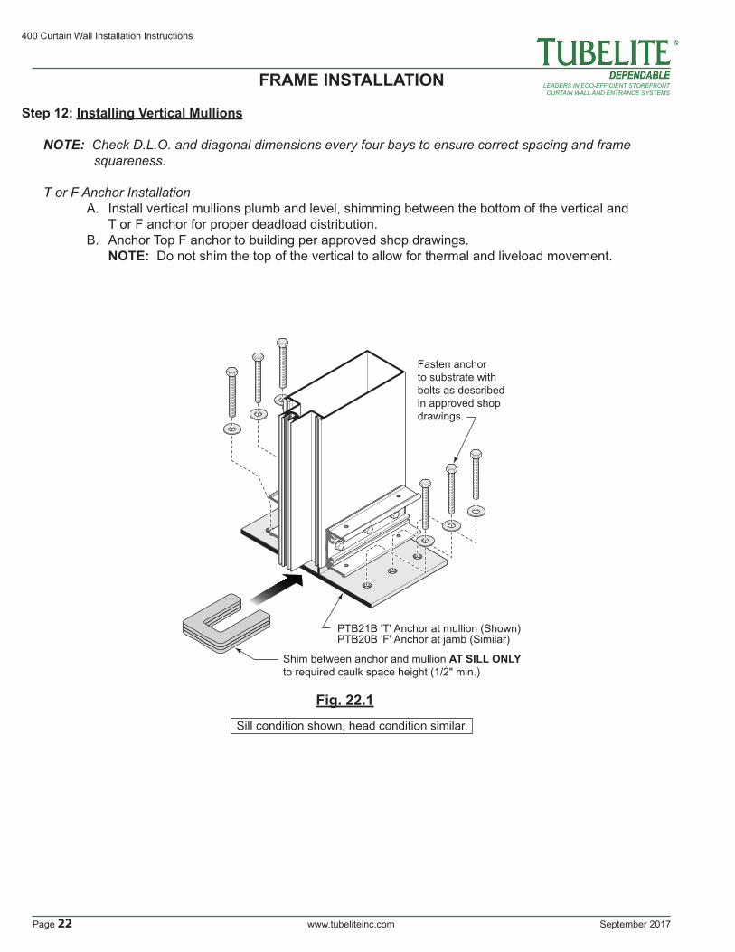
Step 12: Installing Vertical Mullions
NOTE: Check D.L.O. and diagonal dimensions every four bays to ensure correct spacing and frame squareness. T or F Anchor Installation A. Install vertical mullions plumb and level, shimming between the bottom of the vertical and T or F anchor for proper deadload distribution. B. Anchor Top F anchor to building per approved shop drawings. NOTE: Do not shim the top of the vertical to allow for thermal and liveload movement.
FRAME INSTALLATION
Shim between anchor and mullion AT SILL ONLYto required caulk space height (1/2" min.)
PTB21B 'T' Anchor at mullion (Shown) PTB20B 'F' Anchor at jamb (Similar)
Fasten anchor to substrate with bolts as described in approved shop drawings.
Fig. 22.1Sill condition shown, head condition similar.

September 2017 www.tubeliteinc.com Page 23
400 Curtain Wall Installation Instructions
LEADERS IN ECO-EFFICIENT STOREFRONTCURTAIN WALL AND ENTRANCE SYSTEMS
1½"
Apply sealant to exterior joint of shear block and mullion prior to installing horizontal
Apply sealant to each end of horizontal
Step 13: Attach Horizontals to Shear Blocks and Anchor Clips
A. Insert a P1094 ethafoam rod into the void of the tongue of the horizontal members, pushing it about 1/8” past flush to allow room for sealant. See Fig. 23.1.B. Seal shear block prior to installing the horizontal member. See Fig. 23.2.C. Seal the ends of the horizontal back member and attach to the shear block using S270 screws. Seal the heads of the screws as shown in Fig. 23.3. D. Install (2) S6505 flat head screws on the bottom of horizontal as shown in Fig. 23.3. E. Tool sealant at the horizontal/vertical intersection. See Fig. 23.3.
⅛"
2" long P1094 backer rodat each end
Cap seal screw headsSecure horizontal to clip with (2) S270 screws.
Tool excess sealant
S6505
Fig. 23.1
Fig. 23.3
Fig. 23.2TYPICAL TUBULAR HORIZONTAL INSTALLATION
NOTE: See Step 9 for shear block attachment.
FRAME FABRICATION

400 Curtain Wall Installation Instructions
Page 24 www.tubeliteinc.com September 2017
LEADERS IN ECO-EFFICIENT STOREFRONTCURTAIN WALL AND ENTRANCE SYSTEMS
Step 13: Attach Horizontals to Shear Blocks and Anchor Clips (Continued)
LAST BAY TUBULAR HORIZONTAL INSTALLATION
1½"
15/32"
Rip-off legs flush to screw splines as shown.
MODIFY SHEAR BLOCKfor last bay installation of tubular horizontals
Apply sealant to exterior joint of shear block and mullion proior to installing horizontalSecure horizontal
to clip with (2) S270 screws.
Apply and tool sealant at each end of installed horizontal as shown in Fig. 28.1 - 28.3.
Jamb Mullion
Intermediate Mullion
Fig. 24.1
NOTE: See Step 9 for shear block attachment.
FRAME INSTALLATION

September 2017 www.tubeliteinc.com Page 25
400 Curtain Wall Installation Instructions
LEADERS IN ECO-EFFICIENT STOREFRONTCURTAIN WALL AND ENTRANCE SYSTEMS
Step 14: Install Water Dams
A. Seal the end of the horizontal member across the vertical member, including the P1094 ethafoam rod in the tongue of the horizontal. This sealant should be applied liberally.B. Push the PTB93 water dam into the void between the horizontal member and the vertical tongue. This is a pressure fit; the water dam should be level with the top of the horizontal tongue.C. Seal over the top of the PTB93 onto the horizontal tongue, damming the end of the horizontals. THIS IS A CRITICAL SEAL.
Backer rod
Apply sealant to the three (3) contact surfaces that receive water dam
PTB93Water dam
Backer rod(Dashed)
Fig. 25.1
FRAME INSTALLATION

400 Curtain Wall Installation Instructions
Page 26 www.tubeliteinc.com September 2017
LEADERS IN ECO-EFFICIENT STOREFRONTCURTAIN WALL AND ENTRANCE SYSTEMS
Step 15: Seal Perimeter of Installation
A. Apply sealant into gasket reglet as shown in Fig. 26.1. B. Insert backer rod into the gap between the building substrate and curtain wall frame. C. Apply sealant around the perimeter of the frame and tool the sealant. See Fig. 26.2 and Fig. 26.3.
NOTE: Exterior and Interior perimeter seals must run continuous full perimeter of framing.
Head and Sill
½"
½"
½"
Exterior seal(Weather seal)
Interior seal
½"
Exteriorseal (Weather seal)
Interiorseal
(Min.) (Min.) (Min
.)(M
in.)
½"
Exterior (shown)Interior (Similar)
Backer rod
Perimeter seal
(Min.)
¼"
Fig. 26.2Fig. 26.1
FRAME INSTALLATION
Apply sealant into gasket reglets at bottom of mullion as shown. 2"
Sill application shown, head application similar
Fig. 26.3

September 2017 www.tubeliteinc.com Page 27
400 Curtain Wall Installation Instructions
LEADERS IN ECO-EFFICIENT STOREFRONTCURTAIN WALL AND ENTRANCE SYSTEMS
Step 16: Glazing PreparationA. Remove any debris from the glazing pockets.B. Trim excess silicone from edges of glazing units to allow for maximum glazing clearance.
Glazing pockets are designed to accept a variety of infill thicknesses. Refer to our online System Glazing Chart for a full list of glazing size options for this system:
http://www.tubeliteinc.com/wp-content/uploads/2014/05/Tubelite_Glazing_Chart.pdf
Step 16: Install Gaskets
NOTE: Crowd gaskets toward the center of the member during installation to avoid gaps caused by relaxation of the gasket material.A. Install PTB28 gasket into vertical and horizontal pressure plates. See Fig. 27.1.
Fig. 27.1
Crowd excess gasket length toward the middle of pressure bar extrusion.
Press gaskets into reglets
See page 18 for gasket cut lengths
GLAZING

400 Curtain Wall Installation Instructions
Page 28 www.tubeliteinc.com September 2017
LEADERS IN ECO-EFFICIENT STOREFRONTCURTAIN WALL AND ENTRANCE SYSTEMS
PTB94
PTB94
Fig. 28.1
Fig. 28.2
Step 17: Install Gaskets (Continued)B. Install PTB94 isolator gasket into vertical and horizontal tongues. Run the isolator through the vertical splice joints. See Fig. 28.1.
GLAZING
Lift and seal ends of horizontal gaskets.Press gasket back in place and tool excess sealant.
NOTE:This operation should take place just prior to glazing. Sealant must be wet when glass is being set.
Step 18: Installing Glass
NOTE: Pre-seal gaskets only in the opening to be glazed to avoid sealant curing and contamination before glass is set in place.
A. Pull interior horizontal gaskets away from vertical gaskets and seal corners where gaskets abut. Release horizontal gasket back to its original position. See Fig. 28.2.
September 2017 www.tubeliteinc.com Page 29
400 Curtain Wall Installation Instructions
LEADERS IN ECO-EFFICIENT STOREFRONTCURTAIN WALL AND ENTRANCE SYSTEMS
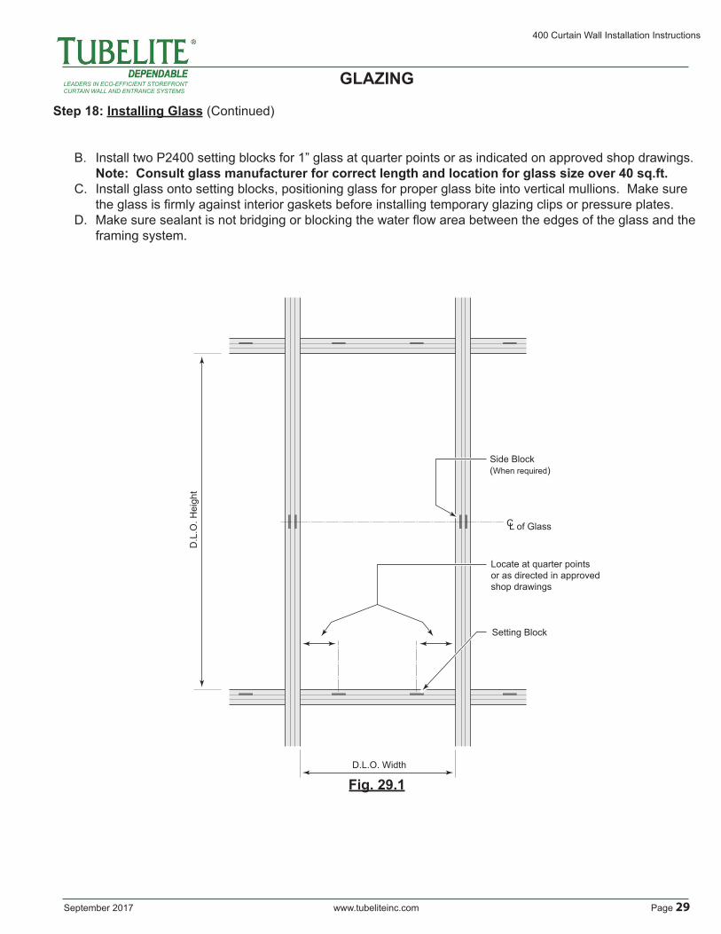
Step 18: Installing Glass (Continued)
B. Install two P2400 setting blocks for 1” glass at quarter points or as indicated on approved shop drawings. Note: Consult glass manufacturer for correct length and location for glass size over 40 sq.ft.C. Install glass onto setting blocks, positioning glass for proper glass bite into vertical mullions. Make sure the glass is firmly against interior gaskets before installing temporary glazing clips or pressure plates.D. Make sure sealant is not bridging or blocking the water flow area between the edges of the glass and the framing system.
GLAZING
D.L.O. Width
D.L
.O. H
eigh
t
Locate at quarter points or as directed in approved shop drawings
Side Block(When required)
Setting Block
C L of Glass
Fig. 29.1

400 Curtain Wall Installation Instructions
Page 30 www.tubeliteinc.com September 2017
LEADERS IN ECO-EFFICIENT STOREFRONTCURTAIN WALL AND ENTRANCE SYSTEMS
Step 18: Installing Glass (Continued)
E. Hold the glass in place using P1194 temporary glazing clips. Locate clips near each corner of the glass and at mid points. Temporary glazing retainers are intended for short term use only. Additional retainers or full length pressure plates may be required if high windload pressures are anticipated before the installation is complete.
P1194
PTB93Water Dam
PTB93Water Dam
P1194
Torque temporary glass retainer boltsto 30 inch pounds.Do not over torque.
P2400Setting Block
GLAZING
Fig. 30.1
Fig. 30.2

September 2017 www.tubeliteinc.com Page 31
400 Curtain Wall Installation Instructions
LEADERS IN ECO-EFFICIENT STOREFRONTCURTAIN WALL AND ENTRANCE SYSTEMS
Fig. 31.1
Step 19: Install Pressure Plates and Face Covers
A. Remove temporary glazing retainers from verticals as required.B. Vertical pressure plates must be installed first. Prior to installing, apply sealant to the face of each water dam.C. Install the vertical pressure plates using S359 screws. D. Remove temporary glazing retainers from horizontals as required.E. Install the horizontal pressure plates using S359 screws, ensuring that weep holes are on the top side of the pressure plate.F. Ensure there are anchor holes in the pressure plates 2” max from the ends and 2” max from each horizontal/vertical intersection to maintain proper compression on the glass.G. Torque all pressure plate screws to 30 – 40 in-lbs. When using a cordless drill with a torque limiter, check torque periodically against a torque wrench.H. Install the vertical face covers using a wood block to protect the face cover.I. Seal the horizontal pressure plates to the vertical face covers, tooling the sealant into the joint.J. Install the horizontal face covers with equal gaps on each end. Make sure the weep slots in the face cover are pointing down.
Seal over exposed face Water Dams
Install vertical pressure bars first.
S359(Typ)
Install horizontal pressure bars last.
Anchor clipat Jamb.
Also see Fig. 38.1.
GLAZING

400 Curtain Wall Installation Instructions
Page 32 www.tubeliteinc.com September 2017
LEADERS IN ECO-EFFICIENT STOREFRONTCURTAIN WALL AND ENTRANCE SYSTEMS
S359(Typ)
M4TB63FB
E3162FB
E316
2FB
E316
2FB
M4TB63FB
Fram
e H
eigh
t
6" O
.C.
⅛"
⅛"
3/16"
D.L.O.
8" O.C.3/16"
Ø 7/32" Weep HolesThree (2) per D.L.O.(Typ)
M4T
B63
FBM
4TB
63FB
M4T
B63
FB
2"2"
2" 2"
Fig. 32.1
Step 19: Install Pressure Plates and Face Covers (Continued)
PRESSURE BAR INSTALLATION
GLAZING
September 2017 www.tubeliteinc.com Page 33
400 Curtain Wall Installation Instructions
LEADERS IN ECO-EFFICIENT STOREFRONTCURTAIN WALL AND ENTRANCE SYSTEMS
1/4 Point1/4 Point
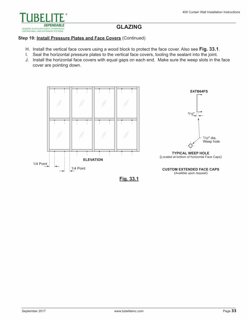
TYPICAL WEEP HOLE(Located at bottom of horizontal Face Caps)
ELEVATION
7/32" dia.Weep hole
E4TB64FS
3/16"
CUSTOM EXTENDED FACE CAPS(Availible upon request)
Step 19: Install Pressure Plates and Face Covers (Continued)
H. Install the vertical face covers using a wood block to protect the face cover. Also see Fig. 33.1.I. Seal the horizontal pressure plates to the vertical face covers, tooling the sealant into the joint.J. Install the horizontal face covers with equal gaps on each end. Make sure the weep slots in the face cover are pointing down.
Fig. 33.1
GLAZING
400 Curtain Wall Installation Instructions
Page 34 www.tubeliteinc.com September 2017
LEADERS IN ECO-EFFICIENT STOREFRONTCURTAIN WALL AND ENTRANCE SYSTEMS
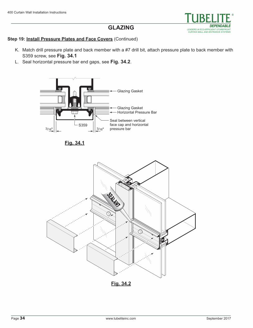
Step 19: Install Pressure Plates and Face Covers (Continued)
K. Match drill pressure plate and back member with a #7 drill bit, attach pressure plate to back member with S359 screw, see Fig. 34.1L. Seal horizontal pressure bar end gaps, see Fig. 34.2.
Fig. 34.1
3/16" 3/16"
Horizontal Pressure Bar
Seal between vertical face cap and horizontal pressure bar
S359
Glazing Gasket
Glazing Gasket
Fig. 34.2
GLAZING

September 2017 www.tubeliteinc.com Page 35
400 Curtain Wall Installation Instructions
LEADERS IN ECO-EFFICIENT STOREFRONTCURTAIN WALL AND ENTRANCE SYSTEMS
NOTE:Always place horizontal caps with weep hole at bottom side.
Install horizontal capsbetween vertical caps
Install vertical caps first.
Use wood block and mallet to prevent denting face caps.
Fig. 35.1FACE CAP INSTALLATION
Step 19: Install Pressure Plates and Face Covers (Continued)
M. Pressure Bar and Face Cap at multi-span mullion splice.
GLAZING

400 Curtain Wall Installation Instructions
Page 36 www.tubeliteinc.com September 2017
LEADERS IN ECO-EFFICIENT STOREFRONTCURTAIN WALL AND ENTRANCE SYSTEMS
ENTRANCE FRAMING
A. All door framing is shipped fabricated from the factory. Curtain wall frames can be installed in the field prior to installing the doors. B. Curtain wall verticals and door subframes run to floor. Bed verticals in sealant and anchor to building per approved shop drawings. See Fig. 36.1 and Fig. 36.2 for possible anchoring methods. Always refer to approved shop drawings for specific requirements.
Mullion at door jamb runs through to substrate.Apply sealant around base of mullion and tool prior to subframe installation.
Sealant to fully cover door frame jamb area.FOOT PRINT of
DOORFRAMEand
THRESHOLD
E3550
Apply liberal amount of sealant at interior and exterior of threshold.
Fig. 36.2Fig. 36.3
ENTRANCE FRAMING
1¾"
¾"
¾"
EQ
.E
Q.
PTB22PTB22
Fig. 36.1

September 2017 www.tubeliteinc.com Page 37
400 Curtain Wall Installation Instructions
LEADERS IN ECO-EFFICIENT STOREFRONTCURTAIN WALL AND ENTRANCE SYSTEMS
ENTRANCE FRAMING (Continued)
C. SUBFRAME INSTALLATION ● Prep the curtain wall frame with pocket closures or as detailed on approved shop drawings. ● Prior to installing the subframe, lay down a bed of sealant where the threshold will be installed. See Fig. 36.2 and Fig. 36.3. ● Install subframe onto curtain wall mullion, shimming equally from side to side. Attach subframe per approved shop drawings. Seal joint between subframe and curtain wall. ● Seal the top of the jamb subframe as shown in Fig. 37.3. ● Attach threshold to building per approved shop drawings. ● Install door per Tubelite’s Entrances and Frames Installation Manual.
Tool any excess sealant around jambs, header and threshold.
Fill bottom of jamb pockets with sealant up to and exceeding the threshold height.
Sealant at base of door jamb assembly
DoorJamb
Mullion
Thre
shol
d
Seal full exterior contour of mullion, sub-frame jamb and threshold at intersection with finished floor.Sealant should merge with perimeter sealant of adjacent framing.
Fill jamb pocket at threshold. Sealant depth to be flush with top of threshold.
Screws at header Fig. 37.1
Fig. 37.2 Fig. 37.3
ENTRANCE FRAMING
Install end dams and seals as shown in step 16 on pages 46 and 47.
Seal interior and exterior shim space.
Seal intersection of jamb to head joint

400 Curtain Wall Installation Instructions
Page 38 www.tubeliteinc.com September 2017
LEADERS IN ECO-EFFICIENT STOREFRONTCURTAIN WALL AND ENTRANCE SYSTEMS
REGLAZING
A. Reglazing is done from the exterior.B. Carefully remove face covers surrounding the lite to be removed.C. Remove vertical and horizontal pressure plates adjacent to affected lite.D. Temp surrounding glass in place with P1194 temporary clips per Step 18, pages.E. Remove lite of glass and gaskets from opening. Clean debris and sealant from the glass pocket and glazing reglets.F. Install new glass in opening per Steps 16 through 20, pages 27 through 35.
REGLAZING