Embed Size (px)
Citation preview

August 2016 www.tubeliteinc.com Page 13056 Walker Ridge Dr. NW, Suite G ● Walker, MI 49544 ● 800-866-2227
INSTALLATION INSTRUCTIONS400 SERIES
HURRICANE RESISTANT CURTAIN WALL

400 Curtain Wall Installation Instructions
Page 2 www.tubeliteinc.com August 2016
LEADERS IN ECO-EFFICIENT STOREFRONTCURTAIN WALL AND ENTRANCE SYSTEMS
BLANK
August 2016 www.tubeliteinc.com Page 3
400 Curtain Wall Installation Instructions
LEADERS IN ECO-EFFICIENT STOREFRONTCURTAIN WALL AND ENTRANCE SYSTEMS
GENERAL CONSTRUCTION NOTES .................................................................................................. 4-5
QUICK REFERENCE CHECKLIST ......................................................................................................... 5
PARTS LIST ................................................................................................................................ 6-9
ELEVATION TYPES and DETAILS .................................................................................................. 10-16
FRAME FABRICATION Step 1 Determine Frame Size ............................................................................................. 17 Step 2 Cut Material to Length ............................................................................................. 18 Step 3 Drill Verticals for Shear Blocks ................................................................................. 19 Step 4 Drill Horizontals for Shear Block Attachment ........................................................... 20 Step 5 Fabricate Pressure Bars .......................................................................................... 21 Step 6 Fabricate Weep Slots in Face Covers ..................................................................... 22 Step 7 Notch Head & Sill for Anchor Clearance .................................................................. 22 Step 8 Fabricate Preimeter Anchor ................................................................................ 23-24 Step 9 Install Steel Reinforcement as Required ................................................................. 25 Step 10 Fasten Shear Clip to Vertical ................................................................................... 26 Step 11 Install Head and Sill ‘F’ and ‘T’ Anchors ................................................................... 27 FRAME INSTALLATION Step 12 Installing Vertical Mullions ........................................................................................ 28 Step 13 Splice Sleeve Installation ......................................................................................... 29 Step 14 Attach Horizontals to Shear Blocks .................................................................... 30-31 Step 15 Install Water Dams................................................................................................... 32 Step 16 Apply Perimeter Seal to Installation ......................................................................... 33
GLAZING Step 17 Glazing Preparation ................................................................................................. 34 Step 18 Installing Gaskets and Spacers .......................................................................... 34-35 Step 19 Installing Glass ................................................................................................... 36-38 Step 20 Install Pressure Plates and Face Covers ............................................................ 39-46
ENTRANCE FRAMING ..................................................................................................................... 47-48
REGLAZING ................................................................................................................................. 49 CORNER CONDITIONS Outside Corner Exploded View ........................................................................................................ 50
TABLE OF CONTENTS
400 Curtain Wall Installation Instructions
Page 4 www.tubeliteinc.com August 2016
LEADERS IN ECO-EFFICIENT STOREFRONTCURTAIN WALL AND ENTRANCE SYSTEMS
1. These instructions cover typical product application, fabrication, installation and standard conditions and are general in nature. They provide useful guidelines, but the final shop drawings may include additional details specific to the project. Any conflict or discrepancies must be clarified prior to execution.
2. Materials stored at the job site must be kept in a safe place protected from possible damage by other trades. Stack with adequate separation so materials will not rub together and store off the ground. Cardboard or paper wrapped materials must be kept dry. Check arriving materials for quantity and keep a record of where various materials are stored.
3. All field welding must be done in accordance with AISC guidelines. All aluminum and glass should be shielded from field welding to avoid damage from weld splatter. Results will be unsightly and may be structurally unsound. Advise general contractor and other trades accordingly.
4. Coordinate protection of installed work with general contractor and/or other trades.
5. Coordinate sequence of other trades which affect framing installation with the general contractor (e.g. fire proofing, back up walls, partitions, ceilings, mechanical ducts, HVAC, etc.).
6. General contractor should furnish and guarantee bench marks, offset lines and opening dimensions. These items should be checked for accuracy before proceeding with erection. Make certain that all adjacent substrate construction is in accordance with the contract documents and/or approved shop drawings. If not, notify the general contractor in writing before proceeding with installation because this could constitute acceptance of adjacent substrate construction by others.
7. Isolate all aluminum to be placed directly in contact with masonry or other incompatible materials with a heavy coat of zinc chromate or bituminous paint. Fasteners attaching framing to building structure are typically not provided by Tubelite.
8. Sealant selection is the responsibility of the erector, installer and/or glazing contractor and must be approved by the sealant manufacturer with regard to application and compatibility for its intended use. All sealants must be used in strict accordance with the manufacturer’s instructions and applied only by trained personnel to surfaces that have been properly prepared.
9. Sealant must be compatible with all materials with which they have contact, including other sealant surfaces. Consult the sealant manufacturer for recommendations relative to shelf life, compatibility, cleaning of substrate, priming, tooling adhesion, etc. Recommend sealant manufacturer perform adhesion “pull test” at “wet” glazing for quality assurance.
10. Drainage gutters and weep holes must be kept clean at all times. Tubelite will not accept responsibility for improper drainage as a result of clogged gutters and weep holes.
11. This product requires clearances at the head, sill and jambs to allow for thermal expansion and contraction as well as construction tolerances. Refer to final distribution drawings for joint sizes. Joints smaller than 1/4” may be subject to failure. Consult the sealant manufacturer for proper sizing of joints.
12. All framing members, entrances and other materials are to be installed plumb, level and true with regard to established bench marks, column center lines or other working points established by the general contractor and checked by the erector, installer and/or glazing contractor.
13. After sealant is set and a representative amount of the wall has been glazed (500 square feet or more), run a water hose test to check installation. On large projects, a hose test should be repeated during glazing operation. This testing should be conducted in accordance with AAMA 501.2 specifications.
14. Cleaning of exposed aluminum surfaces should be done per AAMA recommendations. 15. Care must be taken when assembling aluminum framing components. Over tightening any fastener may cause stripping or fastener failure. Tubelite recommends the use of drill motors with clutches engaged to provide satisfactory tightening of the screw while preventing over torque. The use of impact drill motors is not recommended due to the absence of a clutch device. 16. Check www.tubeliteinc.com for any installation instruction updates.
GENERAL CONSTRUCTION NOTES
August 2016 www.tubeliteinc.com Page 5
400 Curtain Wall Installation Instructions
LEADERS IN ECO-EFFICIENT STOREFRONTCURTAIN WALL AND ENTRANCE SYSTEMS
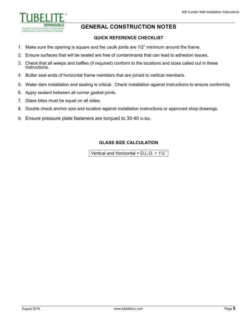
QUICK REFERENCE CHECKLIST
1. Make sure the opening is square and the caulk joints are 1/2” minimum around the frame.
2. Ensure surfaces that will be sealed are free of contaminants that can lead to adhesion issues.
3. Check that all weeps and baffles (if required) conform to the locations and sizes called out in these instructions.
4. Butter seal ends of horizontal frame members that are joined to vertical members.
5. Water dam installation and sealing is critical. Check installation against instructions to ensure conformity.
6. Apply sealant between all corner gasket joints.
7. Glass bites must be equal on all sides.
8. Double check anchor size and location against installation instructions or approved shop drawings.
9. Ensure pressure plate fasteners are torqued to 30-40 in-lbs.
GLASS SIZE CALCULATION
Vertical and Horizontal = D.L.O. + 1¼”
GENERAL CONSTRUCTION NOTES
400 Curtain Wall Installation Instructions
Page 6 www.tubeliteinc.com August 2016
LEADERS IN ECO-EFFICIENT STOREFRONTCURTAIN WALL AND ENTRANCE SYSTEMS
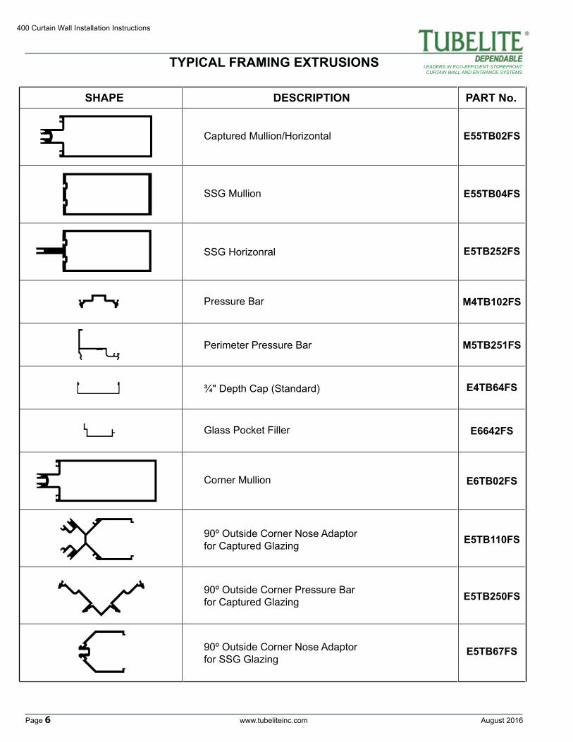
TYPICAL FRAMING EXTRUSIONS
SHAPE DESCRIPTION PART No.
Captured Mullion/Horizontal
SSG Mullion
SSG Horizonral
Pressure Bar
Glass Pocket Filler
¾" Depth Cap (Standard)
Perimeter Pressure Bar
M4TB102FS
M5TB251FS
E4TB64FS
E6642FS
E55TB02FS
90º Outside Corner Nose Adaptorfor Captured Glazing
Corner Mullion
90º Outside Corner Nose Adaptorfor SSG Glazing
90º Outside Corner Pressure Barfor Captured Glazing
E5TB110FS
E5TB250FS
E55TB04FS
E6TB02FS
E5TB67FS
E5TB252FS
August 2016 www.tubeliteinc.com Page 7
400 Curtain Wall Installation Instructions
LEADERS IN ECO-EFFICIENT STOREFRONTCURTAIN WALL AND ENTRANCE SYSTEMS
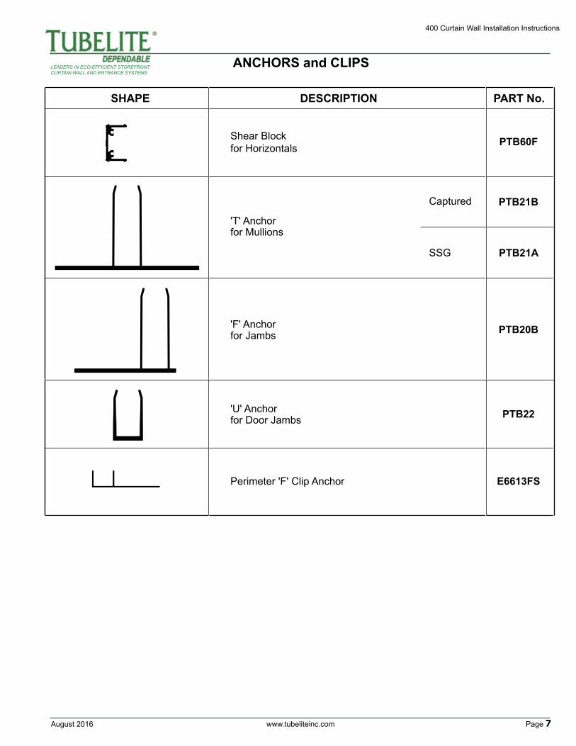
ANCHORS and CLIPS
SHAPE DESCRIPTION PART No.
Shear Block for Horizontals
'T' Anchor for Mullions
Captured
SSG
'F' Anchor for Jambs
Perimeter 'F' Clip Anchor
'U' Anchor for Door Jambs
PTB60F
PTB21B
PTB21A
PTB20B
PTB22
E6613FS
400 Curtain Wall Installation Instructions
Page 8 www.tubeliteinc.com August 2016
LEADERS IN ECO-EFFICIENT STOREFRONTCURTAIN WALL AND ENTRANCE SYSTEMS
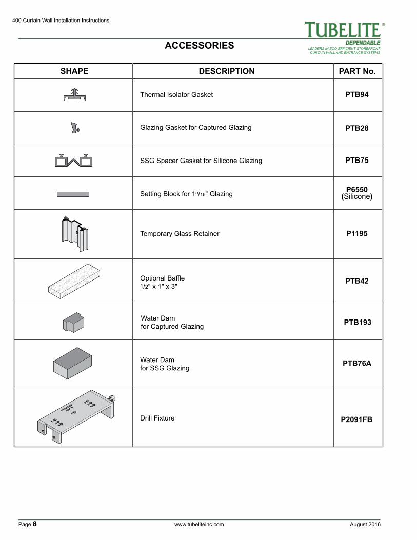
SHAPE DESCRIPTION PART No.
P6550(Silicone)
PTB28
PTB75
PTB42
PTB193
PTB94Thermal Isolator Gasket
Glazing Gasket for Captured Glazing
SSG Spacer Gasket for Silicone Glazing
Setting Block for 15/16" Glazing
P1195Temporary Glass Retainer
Optional Baffle1/2" x 1" x 3"
Water Dam for Captured Glazing
Drill Fixture P2091FBA
A
A
DB
DB
P2091FBW
400CW
PTB76AWater Dam for SSG Glazing
ACCESSORIES
August 2016 www.tubeliteinc.com Page 9
400 Curtain Wall Installation Instructions
LEADERS IN ECO-EFFICIENT STOREFRONTCURTAIN WALL AND ENTRANCE SYSTEMS
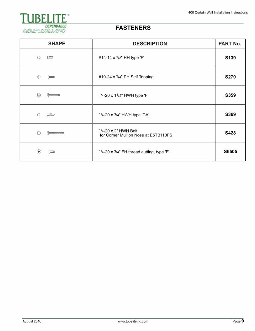
SHAPE DESCRIPTION PART No.
S428
S6505
S359
S369
S270
S139#14-14 x 1/2" HH type 'F'
#10-24 x 3/4" PH Self Tapping
1/4-20 x 11/2" HWH type 'F'
1/4-20 x 3/4" HWH type 'CA'
1/4-20 x 3/4" FH thread cutting, type 'F'
1/4-20 x 2" HWH Bolt for Corner Mullion Nose at E5TB110FS
FASTENERS
400 Curtain Wall Installation Instructions
Page 10 www.tubeliteinc.com August 2016
LEADERS IN ECO-EFFICIENT STOREFRONTCURTAIN WALL AND ENTRANCE SYSTEMS
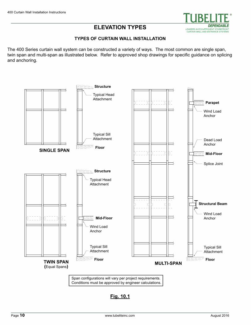
ELEVATION TYPES
SINGLE SPAN
MULTI-SPAN
Parapet
Mid-Floor
Mid-Floor
FloorFloor
Structure
Structure
Floor
Structural Beam
TWIN SPAN(Equal Spans)
Typical HeadAttachment
Typical Sill Attachment
Typical HeadAttachment
Wind LoadAnchor
Typical SillAttachment
Wind LoadAnchor
Wind LoadAnchor
Typical SillAttachment
Dead LoadAnchor
Span configurations will vary per project requirements.Conditions must be approved by engineer calculations.
Splice Joint
Fig. 10.1
TYPES OF CURTAIN WALL INSTALLATION
The 400 Series curtain wall system can be constructed a variety of ways. The most common are single span, twin span and multi-span as illustrated below. Refer to approved shop drawings for specific guidance on splicing and anchoring.
August 2016 www.tubeliteinc.com Page 11
400 Curtain Wall Installation Instructions
LEADERS IN ECO-EFFICIENT STOREFRONTCURTAIN WALL AND ENTRANCE SYSTEMS
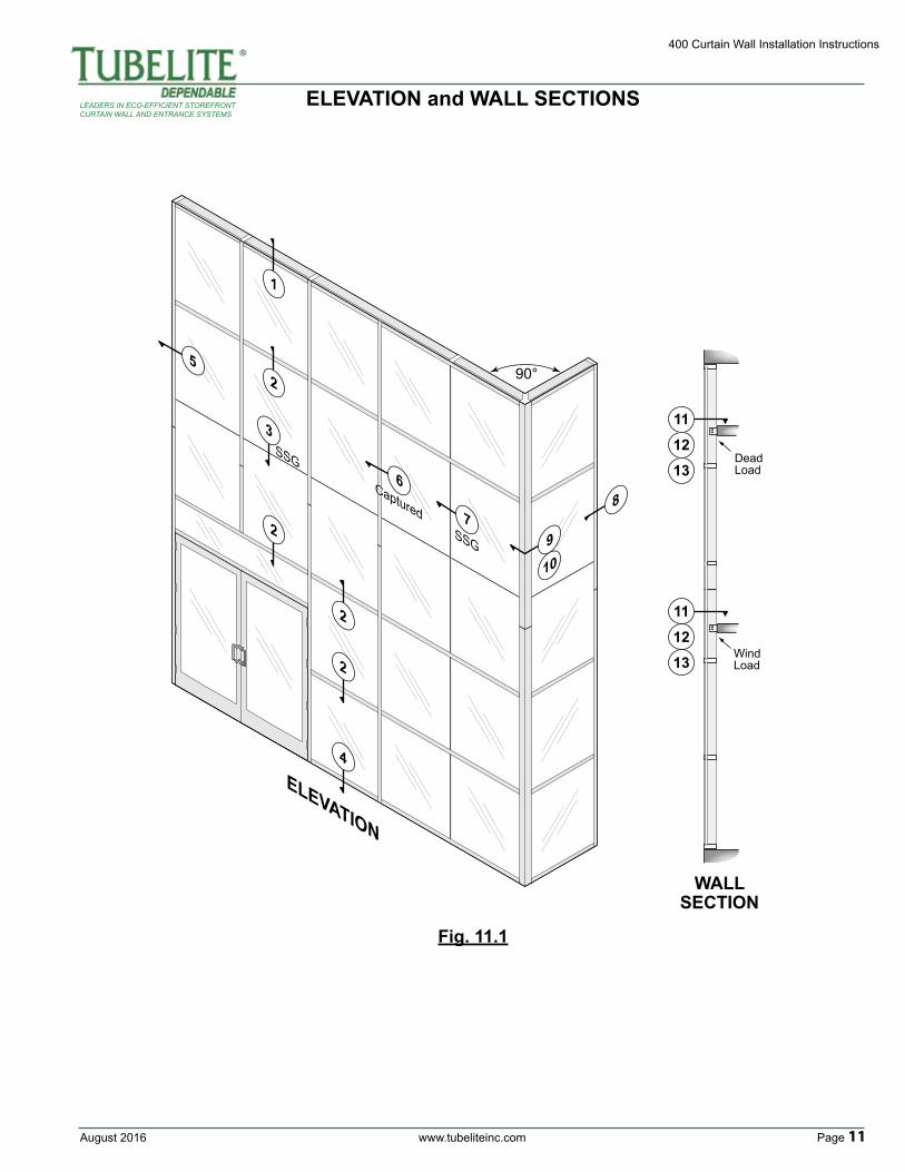
ELEVATION and WALL SECTIONS
90°
Dead Load
Wind Load
ELEVATION
SSG
SSG
Captured
Captured
WALLSECTION
11
11
12
12
13
13
9
10
87
6
5
4
2
3
2
2
2
1
Fig. 11.1
400 Curtain Wall Installation Instructions
Page 12 www.tubeliteinc.com August 2016
LEADERS IN ECO-EFFICIENT STOREFRONTCURTAIN WALL AND ENTRANCE SYSTEMS
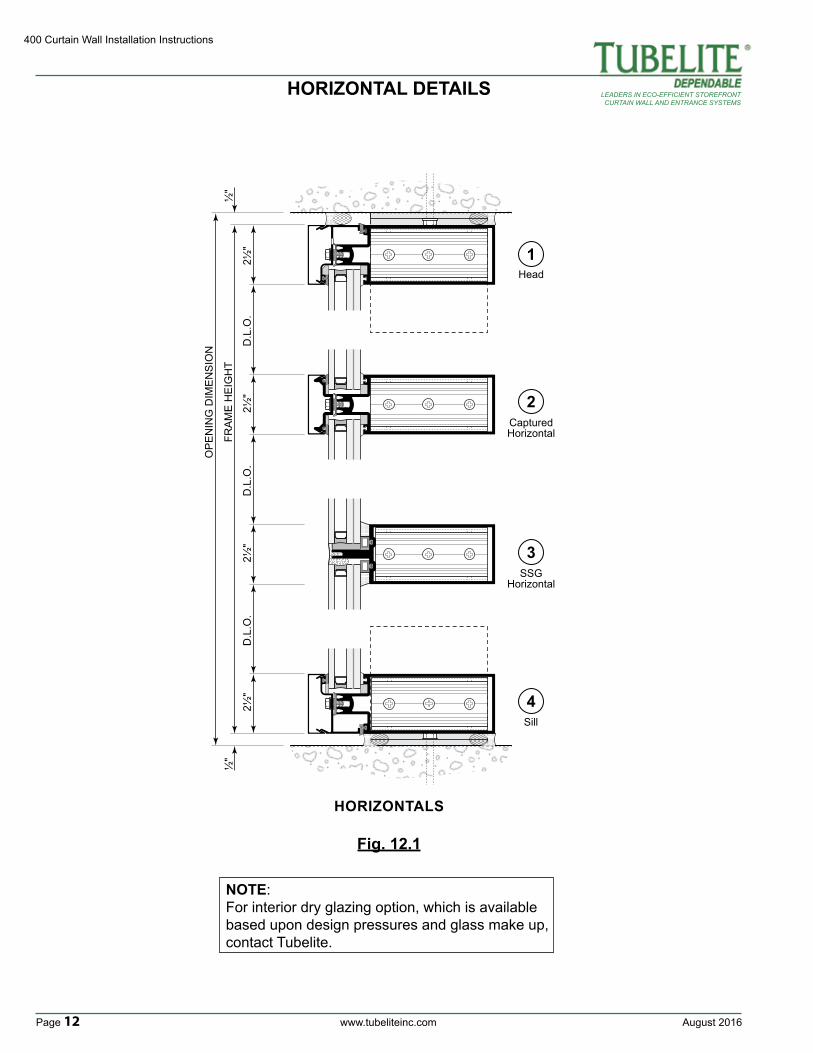
HORIZONTAL DETAILS
Fig. 12.1
HORIZONTALS
2½"
FRA
ME
HE
IGH
T
OP
EN
ING
DIM
EN
SIO
N
2½"
2½"
½"
D.L
.O.
D.L
.O.
2½"
D.L
.O.
½"
1
2
4
Head
CapturedHorizontal
3SSG
Horizontal
Sill
NOTE:For interior dry glazing option, which is available based upon design pressures and glass make up, contact Tubelite.
August 2016 www.tubeliteinc.com Page 13
400 Curtain Wall Installation Instructions
LEADERS IN ECO-EFFICIENT STOREFRONTCURTAIN WALL AND ENTRANCE SYSTEMS
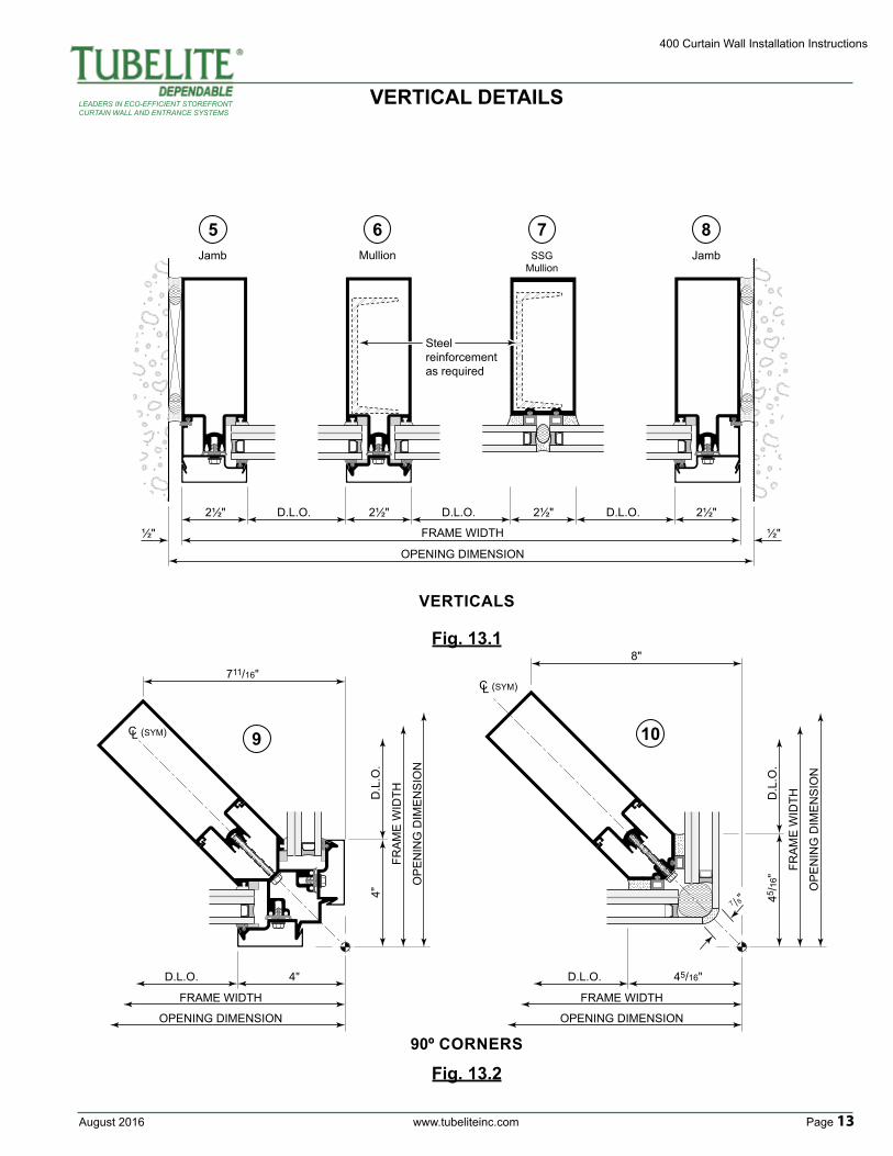
VERTICALS
90º CORNERS
VERTICAL DETAILS
5 6 8Jamb JambMullion
7SSG
Mullion
2½"
FRAME WIDTH
OPENING DIMENSION
2½"2½"
½"
D.L.O. 2½" D.L.O.D.L.O.
½"
Steel reinforcement as required
Fig. 13.1
9
FRAME WIDTH
OPENING DIMENSION
4"
711/16"
D.L.O.
FRA
ME
WID
TH
OP
EN
ING
DIM
EN
SIO
N
4"D
.L.O
.
C L (SYM)
Fig. 13.2
FRAME WIDTH
OPENING DIMENSION
45/16"
7 /8"
8"
D.L.O.
FRA
ME
WID
TH
OP
EN
ING
DIM
EN
SIO
N
45/1
6"D
.L.O
.
C L (SYM)
10
400 Curtain Wall Installation Instructions
Page 14 www.tubeliteinc.com August 2016
LEADERS IN ECO-EFFICIENT STOREFRONTCURTAIN WALL AND ENTRANCE SYSTEMS
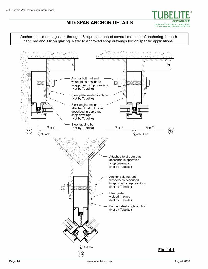
MID-SPAN ANCHOR DETAILS
2"
C L
C C L to L C C L to L
of Mullion12
2"
C L
C C L to L
of Jamb11
Anchor bolt, nut and washers as described in approved shop drawings.(Not by Tubelite)
Steel angle anchor attached to structure as described in approved shop drawings. (Not by Tubelite)
Steel plate welded in place (Not by Tubelite)
Steel tapping bar(Not by Tubelite)
C L of Mullion
13
Anchor bolt, nut and washers as described in approved shop drawings.(Not by Tubelite)
Formed steel angle anchor (Not by Tubelite)
Attached to structure as described in approved shop drawings. (Not by Tubelite)
Steel platewelded in place (Not by Tubelite)
Fig. 14.1
Anchor details on pages 14 through 16 represent one of several methods of anchoring for both captured and silicon glazing. Refer to approved shop drawings for job specific applications.
August 2016 www.tubeliteinc.com Page 15
400 Curtain Wall Installation Instructions
LEADERS IN ECO-EFFICIENT STOREFRONTCURTAIN WALL AND ENTRANCE SYSTEMS
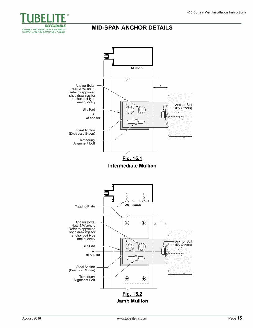
MID-SPAN ANCHOR DETAILS
Intermediate Mullion
Jamb Mullion
C Lof Anchor
2"
Steel Anchor(Dead Load Shown)
Anchor Bolts,Nuts & Washers
Refer to approvedshop drawings for
anchor bolt typeand quantity
TemporaryAlignment Bolt
Slip Pad
Mullion
Anchor Bolt(By Others)
Wall Jamb
2"
Anchor Bolt(By Others)
Tapping Plate
C Lof Anchor
Steel Anchor(Dead Load Shown)
Anchor Bolts,Nuts & Washers
Refer to approvedshop drawings for
anchor bolt typeand quantity
TemporaryAlignment Bolt
Slip Pad
Fig. 15.1
Fig. 15.2
400 Curtain Wall Installation Instructions
Page 16 www.tubeliteinc.com August 2016
LEADERS IN ECO-EFFICIENT STOREFRONTCURTAIN WALL AND ENTRANCE SYSTEMS
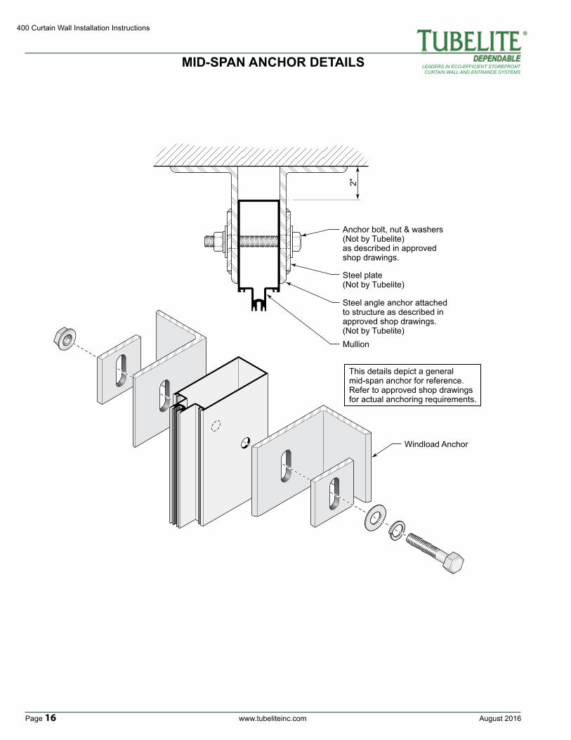
MID-SPAN ANCHOR DETAILS
This details depict a general mid-span anchor for reference.Refer to approved shop drawings for actual anchoring requirements.
2"
Anchor bolt, nut & washers (Not by Tubelite)as described in approved shop drawings.
Steel plate (Not by Tubelite)
Mullion
Steel angle anchor attached to structure as described in approved shop drawings. (Not by Tubelite)
Windload Anchor
August 2016 www.tubeliteinc.com Page 17
400 Curtain Wall Installation Instructions
LEADERS IN ECO-EFFICIENT STOREFRONTCURTAIN WALL AND ENTRANCE SYSTEMS
FRAME FABRICATION
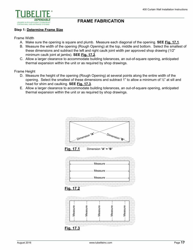
Step 1: Determine Frame Size
Frame WidthA. Make sure the opening is square and plumb. Measure each diagonal of the opening. SEE Fig. 17.1.B. Measure the width of the opening (Rough Opening) at the top, middle and bottom. Select the smallest of these dimensions and subtract the left and right caulk joint width per approved shop drawing (1/2” minimum caulk joint at jambs). SEE Fig. 17.2.C. Allow a larger clearance to accommodate building tolerances, an out-of-square opening, anticipated thermal expansion within the unit or as required by shop drawings.
Frame HeightD. Measure the height of the opening (Rough Opening) at several points along the entire width of the opening. Select the smallest of these dimensions and subtract 1” to allow a minimum of ½” at sill and head for shim and caulking. SEE Fig. 17.3.E. Allow a larger clearance to accommodate building tolerances, an out-of-square opening, anticipated thermal expansion within the unit or as required by shop drawings.
Measure
Dimension "A" = "B"
Measure
Measure
Mea
sure
Mea
sure
Mea
sure
Mea
sure
Mea
sure
Dimension "A" Dimension "B"
Fig. 17.1
Fig. 17.2
Fig. 17.3
400 Curtain Wall Installation Instructions
Page 18 www.tubeliteinc.com August 2016
LEADERS IN ECO-EFFICIENT STOREFRONTCURTAIN WALL AND ENTRANCE SYSTEMS
FRAME FABRICATION
D.L
.O.
D.L
.O.
FRA
ME
HE
IGH
T
2½"
2½"
2½"
D.L.O. D.L.O. D.L.O. D.L.O.
FRAME WIDTH
2½"
2½"2½"2½"
2½"
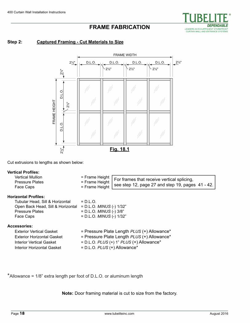
Cut extrusions to lengths as shown below:
Vertical Profiles: Vertical Mullion = Frame Height Pressure Plates = Frame Height Face Caps = Frame Height Horizontal Profiles: Tubular Head, Sill & Horizontal = D.L.O. Open Back Head, Sill & Horizontal = D.L.O. MINUS (-) 1/32” Pressure Plates = D.L.O. MINUS (-) 3/8” Face Caps = D.L.O. MINUS (-) 1/32”
Accessories: Exterior Vertical Gasket = Pressure Plate Length PLUS (+) Allowance* Exterior Horizontal Gasket = Pressure Plate Length PLUS (+) Allowance* Interior Vertical Gasket = D.L.O. PLUS (+) 1” PLUS (+) Allowance* Interior Horizontal Gasket = D.L.O. PLUS (+) Allowance*
Fig. 18.1
Step 2: Captured Framing - Cut Materials to Size
Note: Door framing material is cut to size from the factory.
*Allowance = 1/8” extra length per foot of D.L.O. or aluminum length
For frames that receive vertical splicing, see step 12, page 27 and step 19, pages 41 - 42.
August 2016 www.tubeliteinc.com Page 19
400 Curtain Wall Installation Instructions
LEADERS IN ECO-EFFICIENT STOREFRONTCURTAIN WALL AND ENTRANCE SYSTEMS
FRAME FABRICATION
A
A
A
DB
DB
C
C
P2091FB
400CW
DR
ILL
P2091FBDrill Guidefor capturedverticals only
Align with marked top of horizontal location
Drill vertical members for horizontal shear block attachment.
Fig. 19.3
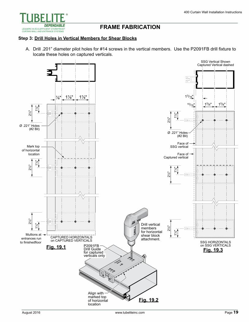
Step 3: Drill Holes in Vertical Members for Shear Blocks
A. Drill .201” diameter pilot holes for #14 screws in the vertical members. Use the P2091FB drill fixture to locate these holes on captured verticals.
2½" 1¼
"
2½" 1¼
"
2½"
1¼"
⅞" 1⅞" 1⅞"
Mark topof horizontal
location
Mullions atentrances run
to finishedfloorCAPTURED HORIZONTALSon CAPTURED VERTICALS
Ø .221” Holes(#2 Bit)
2½" 1¼
"
2½" 1¼
"
2½"
1¼"
15/16"
13/16"
15/8" 15/8"
Ø .221” Holes(#2 Bit)
Face ofSSG vertical
Face ofCaptured vertical
SSG HORIZONTALSon SSG VERTICALS
SSG Vertical ShownCaptured Vertical dashed
Fig. 19.1
Fig. 19.2
400 Curtain Wall Installation Instructions
Page 20 www.tubeliteinc.com August 2016
LEADERS IN ECO-EFFICIENT STOREFRONTCURTAIN WALL AND ENTRANCE SYSTEMS
FRAME FABRICATION
A
A
A
D
B
D
B
CC
P2091FB400CW
DRILL
1¼"
⅝"
⅝"
1¼"
⅝"
1¼"
⅝"
⅝"
⅝"
⅜" Ø .221” Holes(#2 Bit)
Head
IntermediateHorizontal P2091FB
Drill Guide
Sill
Drill exterior flange at each end of horizontalas shown.
NOTE:This opperation alsois required on SSGhorizontals
Fig. 20.1
Fig. 20.2
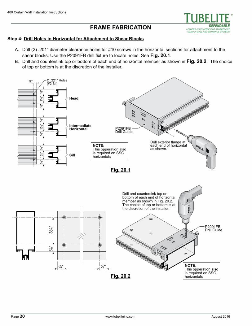
Step 4: Drill Holes in Horizontal for Attachment to Shear Blocks
A. Drill (2) .201” diameter clearance holes for #10 screws in the horizontal sections for attachment to the shear blocks. Use the P2091FB drill fixture to locate holes. See Fig. 20.1.B. Drill and countersink top or bottom of each end of horizontal member as shown in Fig. 20.2. The choice of top or bottom is at the discretion of the installer.
A
A
A
DB
DB
C
C
P2091FB
400CW
DR
ILL
P2091FBDrill Guide
Drill and countersink top or bottom of each end of horizontal member as shown in Fig. 20.2. The choice of top or bottom is at the discretion of the installer.
⅞"
⅞" ⅞"
3¾"
NOTE:This opperation alsois required on SSGhorizontals
August 2016 www.tubeliteinc.com Page 21
400 Curtain Wall Installation Instructions
LEADERS IN ECO-EFFICIENT STOREFRONTCURTAIN WALL AND ENTRANCE SYSTEMS
FRAME FABRICATION
2"2"
6"
Fram
e H
eigh
t
6" O
.C.
2" 2"6"
1/4" Dia. weep hole
9/32" Dia. anchor hole
C L
C L
4" 4"
6" O.C.
D.L.O. minus ⅜"
HORIZONTAL PRESSURE BAR
VERTICAL PRESSURE BAR
6"
M4TB102FS
M4TB102FS
M4TB251FS
M4TB251FSSill (Shown) Head (Dashed)
9/32" Dia.anchor hole
C L of
pressurebar
splice
1" ½"
1"
2"VERTICAL PRESSURE BAR
at SPLICE
Fram
e H
eigh
t
C L of
mullionsplice
Fig. 21.1
Fig. 21.3
Fig. 21.2
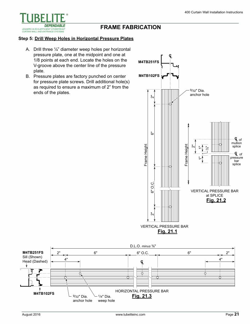
Step 5: Drill Weep Holes in Horizontal Pressure Plates
A. Drill three ¼” diameter weep holes per horizontal pressure plate, one at the midpoint and one at 1/8 points at each end. Locate the holes on the V-groove above the center line of the pressure plate.B. Pressure plates are factory punched on center for pressure plate screws. Drill additional hole(s) as required to ensure a maximum of 2” from the ends of the plates.
400 Curtain Wall Installation Instructions
Page 22 www.tubeliteinc.com August 2016
LEADERS IN ECO-EFFICIENT STOREFRONTCURTAIN WALL AND ENTRANCE SYSTEMS
FRAME FABRICATION
Wall to Wall
33 /8"(Typ)
33 /8"(Typ)
This side to structure
Step 7: Notch Heads and Sills to Clear Shear Clips
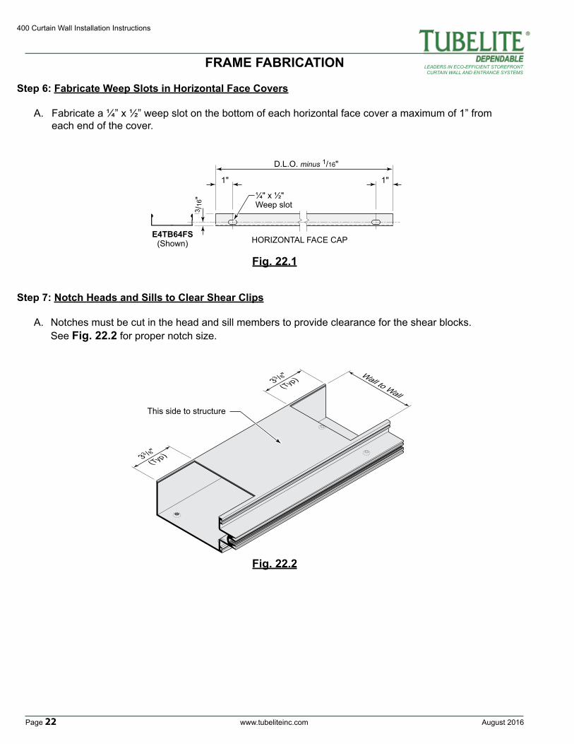
A. Notches must be cut in the head and sill members to provide clearance for the shear blocks. See Fig. 22.2 for proper notch size.
Fig. 22.1
Fig. 22.2
1"
3 /16
" ¼" x ½" Weep slot
D.L.O. minus 1/16"
HORIZONTAL FACE CAPE4TB64FS
(Shown)
1"
Step 6: Fabricate Weep Slots in Horizontal Face Covers
A. Fabricate a ¼” x ½” weep slot on the bottom of each horizontal face cover a maximum of 1” from each end of the cover.
August 2016 www.tubeliteinc.com Page 23
400 Curtain Wall Installation Instructions
LEADERS IN ECO-EFFICIENT STOREFRONTCURTAIN WALL AND ENTRANCE SYSTEMS
Step 8: Fabricate Continuous F-Clip Perimeter Anchor
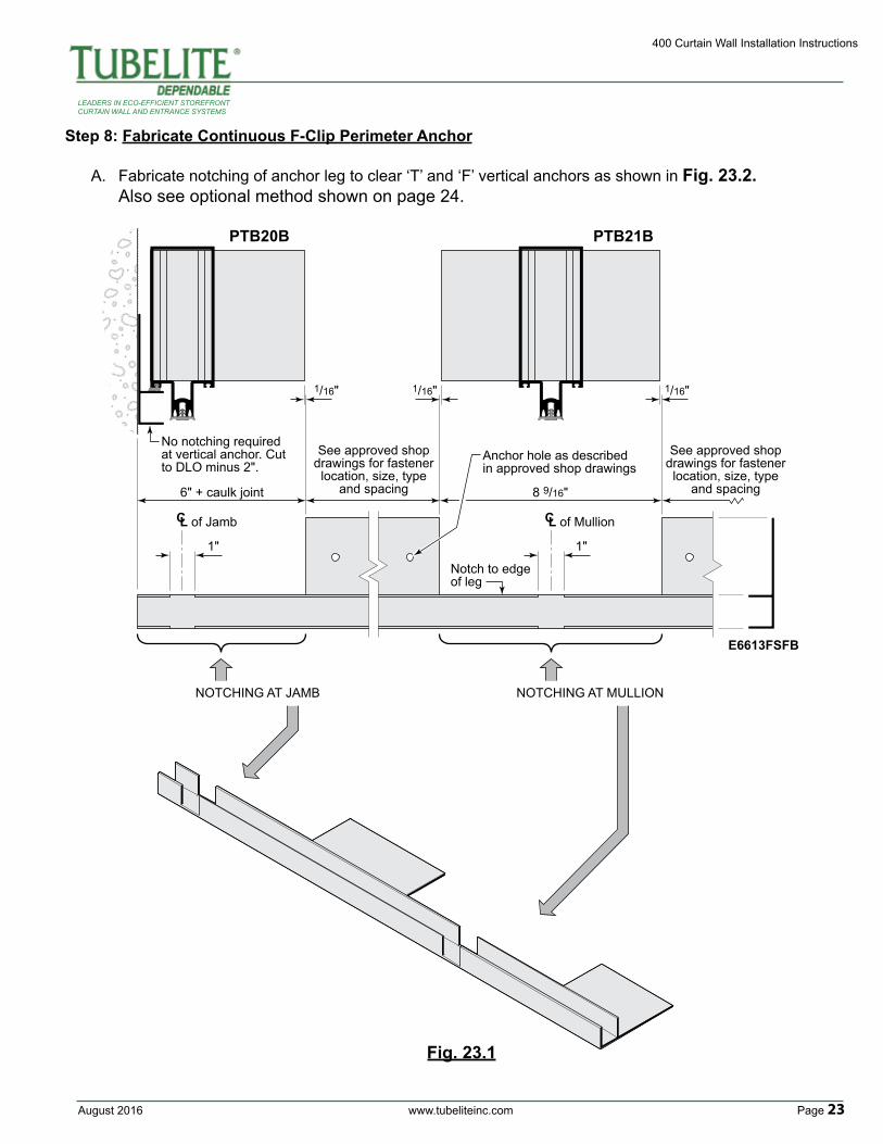
A. Fabricate notching of anchor leg to clear ‘T’ and ‘F’ vertical anchors as shown in Fig. 23.2. Also see optional method shown on page 24.
PTB21BPTB20B
E6613FSFB
C L of Jamb
6" + caulk joint
NOTCHING AT JAMB NOTCHING AT MULLION
8 9/16"
See approved shopdrawings for fastenerlocation, size, type
and spacing
No notching required at vertical anchor. Cut to DLO minus 2".
Notch to edge of leg
Anchor hole as describedin approved shop drawings
See approved shopdrawings for fastenerlocation, size, type
and spacing
1"
1/16" 1/16" 1/16"
1"
C L of Mullion
Fig. 23.1
400 Curtain Wall Installation Instructions
Page 24 www.tubeliteinc.com August 2016
LEADERS IN ECO-EFFICIENT STOREFRONTCURTAIN WALL AND ENTRANCE SYSTEMS
PTB21BPTB20B
E3162FB
C L of Jamb
D.L.O. minus 85/8"See approved shopdrawings for fastenerlocation, size, typeand spacing.
1/16" 1/16" 1/16"
C L of Mullion
C L of mullion
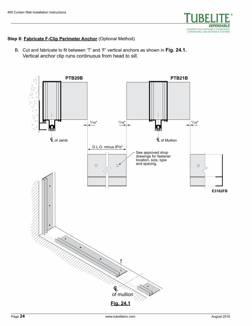
Step 8: Fabricate F-Clip Perimeter Anchor (Optional Method)
B. Cut and fabricate to fit between ‘T’ and ‘F’ vertical anchors as shown in Fig. 24.1. Vertical anchor clip runs continuous from head to sill.
Fig. 24.1

August 2016 www.tubeliteinc.com Page 25
400 Curtain Wall Installation Instructions
LEADERS IN ECO-EFFICIENT STOREFRONTCURTAIN WALL AND ENTRANCE SYSTEMS
Fig. 25.1
Step 9: Install Steel Reinforcement As Required
A. Refer to approved shop drawings to determine where steel reinforcing may be required.B. Steel should be installed prior to the attachment of shear blocks.C. Steel should be sized to stop short of the top and bottom of the vertical for clearance.D. Locate and prep for attachment of the steel located under the horizontal shear blocks if possible. Otherwise, steel can be secured to the vertical mullion through the tongue. Anchor the steel to the vertical using fasteners and spacing per approved shop drawings (not supplied by Tubelite).
TYPICAL APPLICATION
OPTIONAL APPLICATION
CapturedMullion
SSGMullion
SSGMullion
CapturedMullion
Located fasteners as directed in
approved shop drawings
Located fasteners centered on horizontal location when possible.
See approved shop drawing for requirments.
Drill and tap for fastener as required. Countersink for Flat Head screw.
Drill and tap for fastener as required. Countersink for Flat Head screw.
Steel reinforcement shown is for reference only. See
approved shop drawing for steel requirments.
Steel reinforcement shown is for reference only. See
approved shop drawing for steel requirments.
C Lof Horizontal
C Lof Horizontal
FRAME FABRICATION
400 Curtain Wall Installation Instructions
Page 26 www.tubeliteinc.com August 2016
LEADERS IN ECO-EFFICIENT STOREFRONTCURTAIN WALL AND ENTRANCE SYSTEMS
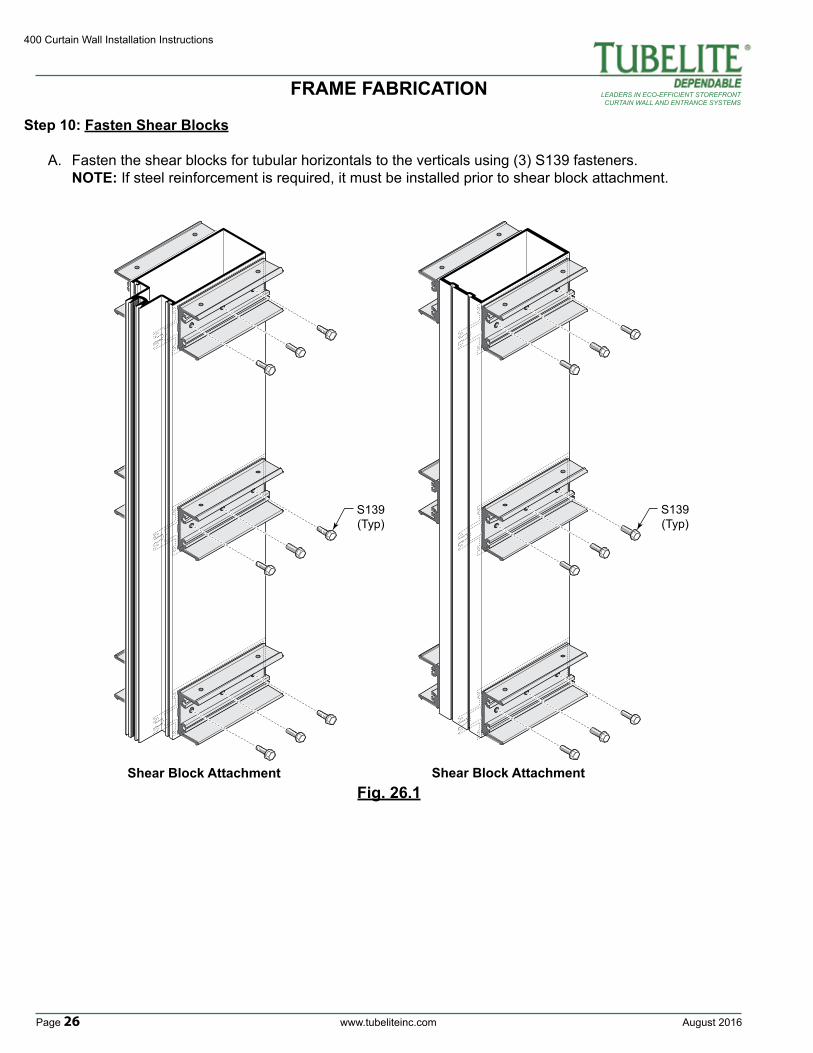
Step 10: Fasten Shear Blocks
A. Fasten the shear blocks for tubular horizontals to the verticals using (3) S139 fasteners. NOTE: If steel reinforcement is required, it must be installed prior to shear block attachment.
S139(Typ)
Shear Block Attachment
S139(Typ)
Shear Block AttachmentFig. 26.1
FRAME FABRICATION
August 2016 www.tubeliteinc.com Page 27
400 Curtain Wall Installation Instructions
LEADERS IN ECO-EFFICIENT STOREFRONTCURTAIN WALL AND ENTRANCE SYSTEMS
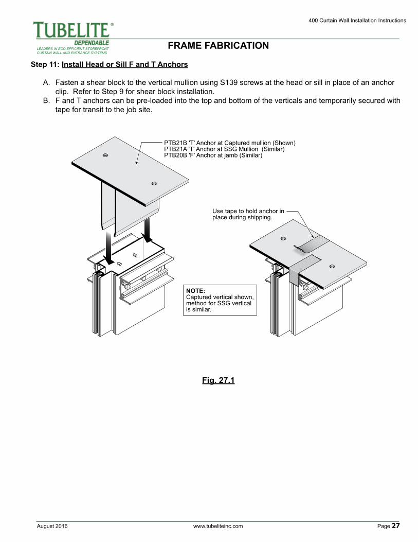
Step 11: Install Head or Sill F and T Anchors
A. Fasten a shear block to the vertical mullion using S139 screws at the head or sill in place of an anchor clip. Refer to Step 9 for shear block installation.B. F and T anchors can be pre-loaded into the top and bottom of the verticals and temporarily secured with tape for transit to the job site.
PTB21B 'T' Anchor at Captured mullion (Shown)PTB21A 'T' Anchor at SSG Mullion (Similar)PTB20B 'F' Anchor at jamb (Similar)
NOTE:Captured vertical shown,method for SSG vertical is similar.
Use tape to hold anchor in place during shipping.
Fig. 27.1
FRAME FABRICATION
400 Curtain Wall Installation Instructions
Page 28 www.tubeliteinc.com August 2016
LEADERS IN ECO-EFFICIENT STOREFRONTCURTAIN WALL AND ENTRANCE SYSTEMS
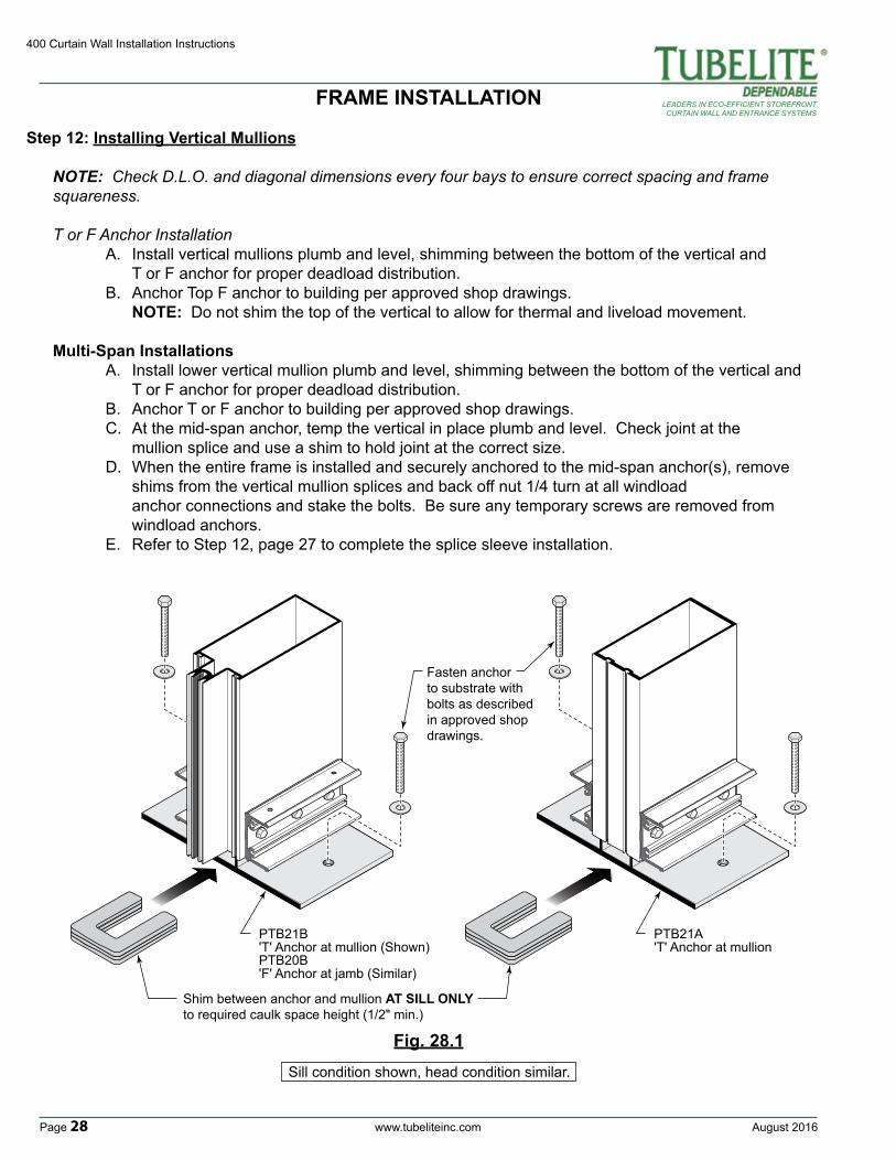
Step 12: Installing Vertical Mullions
NOTE: Check D.L.O. and diagonal dimensions every four bays to ensure correct spacing and frame squareness. T or F Anchor Installation A. Install vertical mullions plumb and level, shimming between the bottom of the vertical and T or F anchor for proper deadload distribution. B. Anchor Top F anchor to building per approved shop drawings. NOTE: Do not shim the top of the vertical to allow for thermal and liveload movement. Multi-Span Installations A. Install lower vertical mullion plumb and level, shimming between the bottom of the vertical and T or F anchor for proper deadload distribution. B. Anchor T or F anchor to building per approved shop drawings. C. At the mid-span anchor, temp the vertical in place plumb and level. Check joint at the mullion splice and use a shim to hold joint at the correct size. D. When the entire frame is installed and securely anchored to the mid-span anchor(s), remove shims from the vertical mullion splices and back off nut 1/4 turn at all windload anchor connections and stake the bolts. Be sure any temporary screws are removed from windload anchors. E. Refer to Step 12, page 27 to complete the splice sleeve installation.
FRAME INSTALLATION
Shim between anchor and mullion AT SILL ONLYto required caulk space height (1/2" min.)
Fasten anchor to substrate with bolts as described in approved shop drawings.
PTB21B 'T' Anchor at mullion (Shown) PTB20B 'F' Anchor at jamb (Similar)
PTB21A 'T' Anchor at mullion
Fig. 28.1Sill condition shown, head condition similar.
August 2016 www.tubeliteinc.com Page 29
400 Curtain Wall Installation Instructions
LEADERS IN ECO-EFFICIENT STOREFRONTCURTAIN WALL AND ENTRANCE SYSTEMS
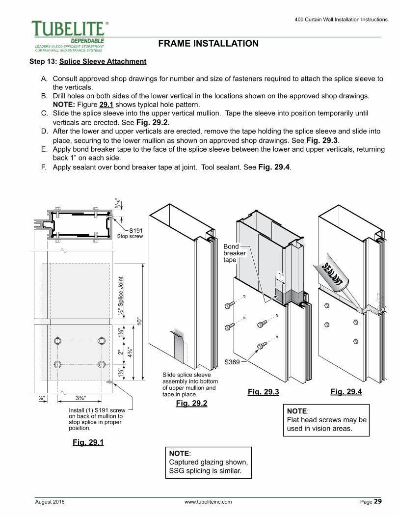
Step 13: Splice Sleeve Attachment
A. Consult approved shop drawings for number and size of fasteners required to attach the splice sleeve to the verticals. B. Drill holes on both sides of the lower vertical in the locations shown on the approved shop drawings. NOTE: Figure 29.1 shows typical hole pattern.C. Slide the splice sleeve into the upper vertical mullion. Tape the sleeve into position temporarily until verticals are erected. See Fig. 29.2.D. After the lower and upper verticals are erected, remove the tape holding the splice sleeve and slide into place, securing to the lower mullion as shown on approved shop drawings. See Fig. 29.3.E. Apply bond breaker tape to the face of the splice sleeve between the lower and upper verticals, returning back 1” on each side. F. Apply sealant over bond breaker tape at joint. Tool sealant. See Fig. 29.4.
10"
4¾"
2"1⅜
"½
" Spl
ice
Join
t1⅜
"
3¾"
S191Stop screw
⅞"
Install (1) S191 screw on back of mullion to stop splice in proper position.
9 /16"
Fig. 29.1
1"
Bond breaker tape
S369
Fig. 29.2Fig. 29.3 Fig. 29.4
Slide splice sleeve assembly into bottom of upper mullion and tape in place.
FRAME INSTALLATION
NOTE:Flat head screws may be used in vision areas.
NOTE:Captured glazing shown,SSG splicing is similar.
400 Curtain Wall Installation Instructions
Page 30 www.tubeliteinc.com August 2016
LEADERS IN ECO-EFFICIENT STOREFRONTCURTAIN WALL AND ENTRANCE SYSTEMS
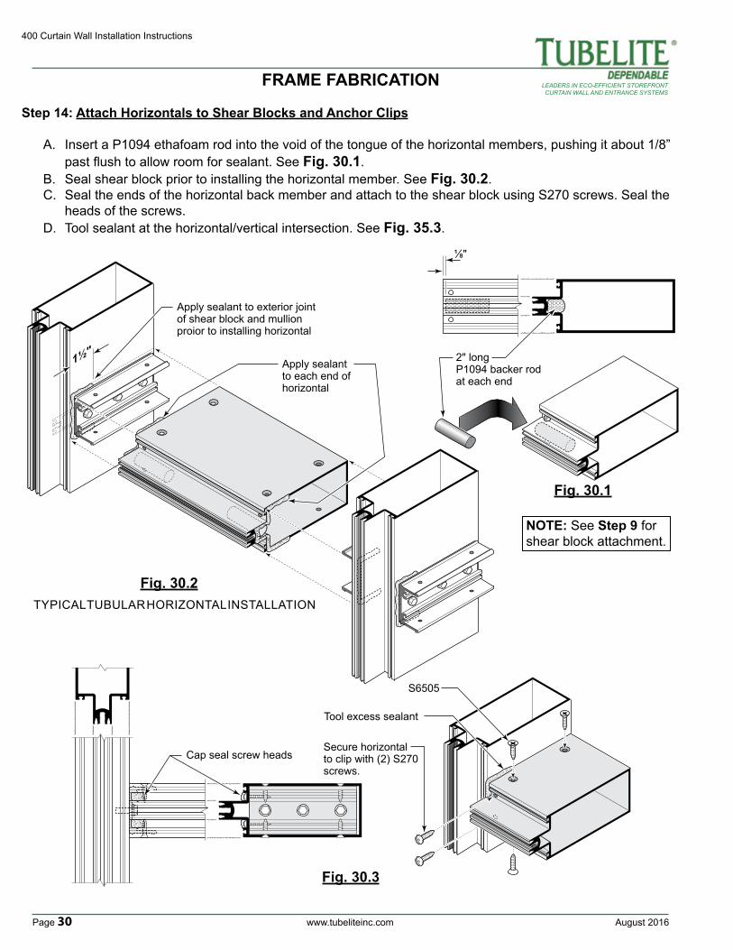
Step 14: Attach Horizontals to Shear Blocks and Anchor Clips
A. Insert a P1094 ethafoam rod into the void of the tongue of the horizontal members, pushing it about 1/8” past flush to allow room for sealant. See Fig. 30.1.B. Seal shear block prior to installing the horizontal member. See Fig. 30.2.C. Seal the ends of the horizontal back member and attach to the shear block using S270 screws. Seal the heads of the screws. D. Tool sealant at the horizontal/vertical intersection. See Fig. 35.3.
⅛"
2" long P1094 backer rodat each end
Cap seal screw headsSecure horizontal to clip with (2) S270 screws.
Tool excess sealant
S6505
Fig. 30.1
Fig. 30.3
Fig. 30.2TYPICAL TUBULAR HORIZONTAL INSTALLATION
1½"
Apply sealant to exterior joint of shear block and mullion proior to installing horizontal
Apply sealant to each end of horizontal
NOTE: See Step 9 for shear block attachment.
FRAME FABRICATION
August 2016 www.tubeliteinc.com Page 31
400 Curtain Wall Installation Instructions
LEADERS IN ECO-EFFICIENT STOREFRONTCURTAIN WALL AND ENTRANCE SYSTEMS
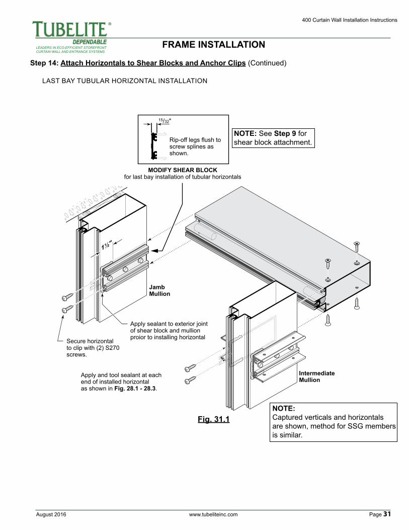
Step 14: Attach Horizontals to Shear Blocks and Anchor Clips (Continued)
LAST BAY TUBULAR HORIZONTAL INSTALLATION
1½"
15/32"
Rip-off legs flush to screw splines as shown.
MODIFY SHEAR BLOCKfor last bay installation of tubular horizontals
Apply sealant to exterior joint of shear block and mullion proior to installing horizontalSecure horizontal
to clip with (2) S270 screws.
Apply and tool sealant at each end of installed horizontal as shown in Fig. 28.1 - 28.3.
Jamb Mullion
Intermediate Mullion
Fig. 31.1
NOTE: See Step 9 for shear block attachment.
NOTE: Captured verticals and horizontals are shown, method for SSG members is similar.
FRAME INSTALLATION
400 Curtain Wall Installation Instructions
Page 32 www.tubeliteinc.com August 2016
LEADERS IN ECO-EFFICIENT STOREFRONTCURTAIN WALL AND ENTRANCE SYSTEMS
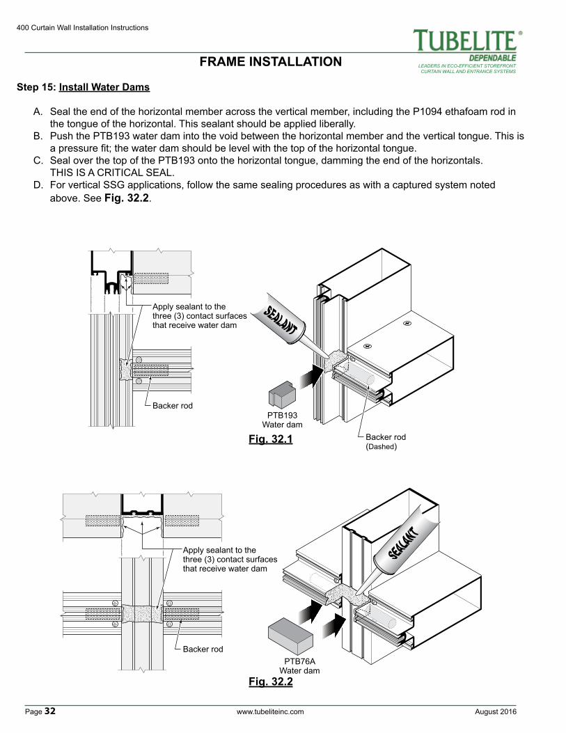
Step 15: Install Water Dams
A. Seal the end of the horizontal member across the vertical member, including the P1094 ethafoam rod in the tongue of the horizontal. This sealant should be applied liberally.B. Push the PTB193 water dam into the void between the horizontal member and the vertical tongue. This is a pressure fit; the water dam should be level with the top of the horizontal tongue.C. Seal over the top of the PTB193 onto the horizontal tongue, damming the end of the horizontals. THIS IS A CRITICAL SEAL.D. For vertical SSG applications, follow the same sealing procedures as with a captured system noted above. See Fig. 32.2.
Backer rod
Apply sealant to the three (3) contact surfaces that receive water dam
PTB193Water dam
Backer rod(Dashed)
Fig. 32.1
Fig. 32.2
FRAME INSTALLATION
Apply sealant to the three (3) contact surfaces that receive water dam
Backer rodPTB76A
Water dam
August 2016 www.tubeliteinc.com Page 33
400 Curtain Wall Installation Instructions
LEADERS IN ECO-EFFICIENT STOREFRONTCURTAIN WALL AND ENTRANCE SYSTEMS
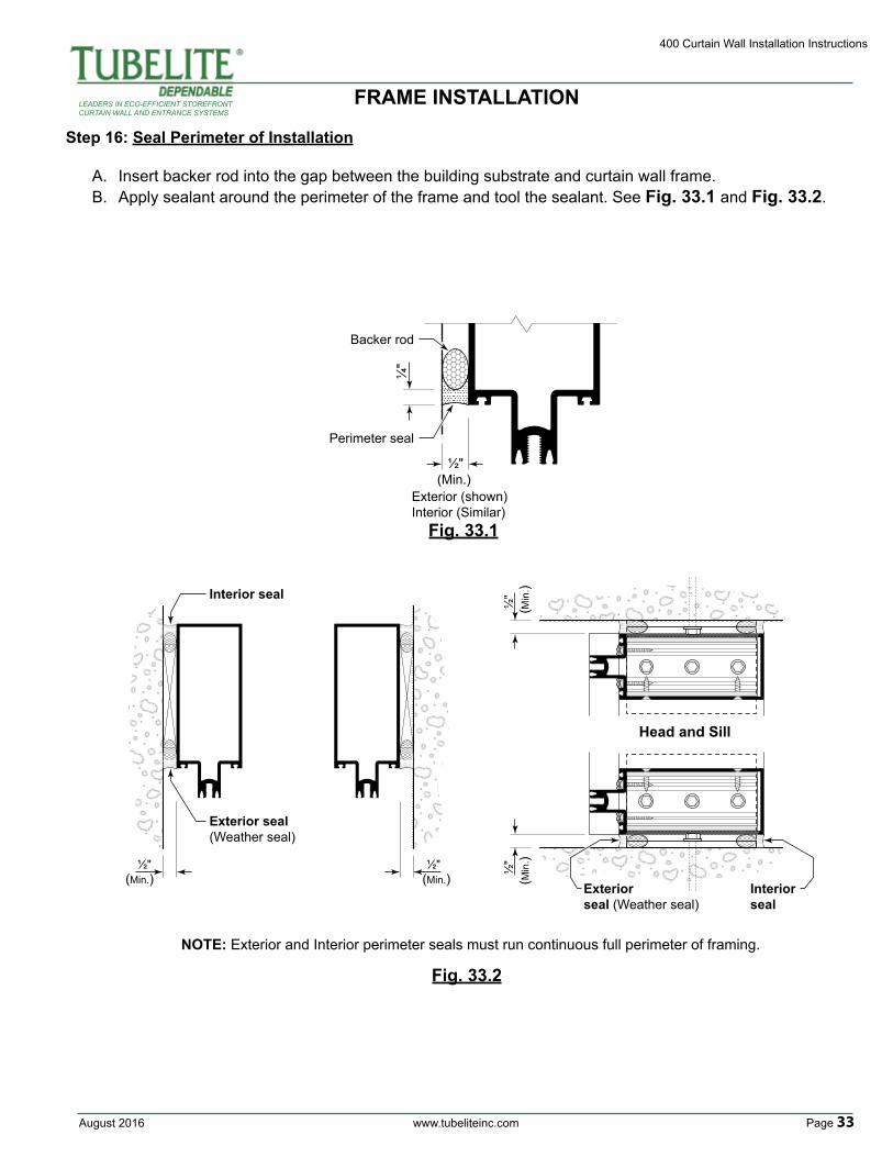
Step 16: Seal Perimeter of Installation
A. Insert backer rod into the gap between the building substrate and curtain wall frame. B. Apply sealant around the perimeter of the frame and tool the sealant. See Fig. 33.1 and Fig. 33.2.
NOTE: Exterior and Interior perimeter seals must run continuous full perimeter of framing.
Head and Sill
½"
½"
½"
Exterior seal(Weather seal)
Interior seal
½"
Exteriorseal (Weather seal)
Interiorseal
(Min.) (Min.) (Min
.)(M
in.)
½"
Exterior (shown)Interior (Similar)
Backer rod
Perimeter seal
(Min.)
¼"
Fig. 33.2
Fig. 33.1
FRAME INSTALLATION
400 Curtain Wall Installation Instructions
Page 34 www.tubeliteinc.com August 2016
LEADERS IN ECO-EFFICIENT STOREFRONTCURTAIN WALL AND ENTRANCE SYSTEMS
Step 17: Glazing PreparationA. Remove any debris from the glazing pockets.B. Trim excess silicone from edges of glazing units to allow for maximum glazing clearance.
Glazing pockets are designed to accept a variety of infill thicknesses. Refer to our online System Glazing Chart for a full list of glazing size options for this system:
http://www.tubeliteinc.com/wp-content/uploads/2014/05/Tubelite_Glazing_Chart.pdf
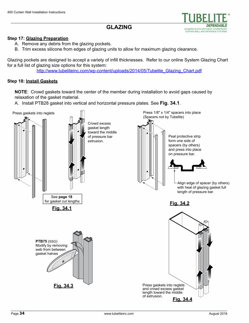
Step 18: Install Gaskets
NOTE: Crowd gaskets toward the center of the member during installation to avoid gaps caused by relaxation of the gasket material.A. Install PTB28 gasket into vertical and horizontal pressure plates. See Fig. 34.1.
Fig. 34.2Fig. 34.1
Crowd excess gasket length toward the middle of pressure bar extrusion.
Press gaskets into reglets
See page 18 for gasket cut lengths
GLAZING
Peal protective strip form one side of spacers (by others) and press into place on pressure bar.
Align edge of spacer (by others) with heal of glazing gasket full length of pressure bar.
Press 1/8" x 1/4" spacers into place(Spacers not by Tubelite)
Press gaskets into reglets and crowd excess gasket length toward the middle of extrusion.
PTB75 (SSG)Modify by removing web from between gasket halves
Fig. 34.3
Fig. 34.4
August 2016 www.tubeliteinc.com Page 35
400 Curtain Wall Installation Instructions
LEADERS IN ECO-EFFICIENT STOREFRONTCURTAIN WALL AND ENTRANCE SYSTEMS
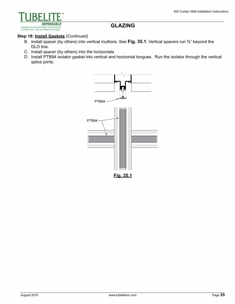
PTB94
PTB94
Fig. 35.1
Step 18: Install Gaskets (Continued)B. Install spacer (by others) into vertical mullions. See Fig. 35.1. Vertical spacers run ⅝” beyond the DLO line.C. Install spacer (by others) into the horizontals.D. Install PTB94 isolator gasket into vertical and horizontal tongues. Run the isolator through the vertical splice joints.
GLAZING
400 Curtain Wall Installation Instructions
Page 36 www.tubeliteinc.com August 2016
LEADERS IN ECO-EFFICIENT STOREFRONTCURTAIN WALL AND ENTRANCE SYSTEMS
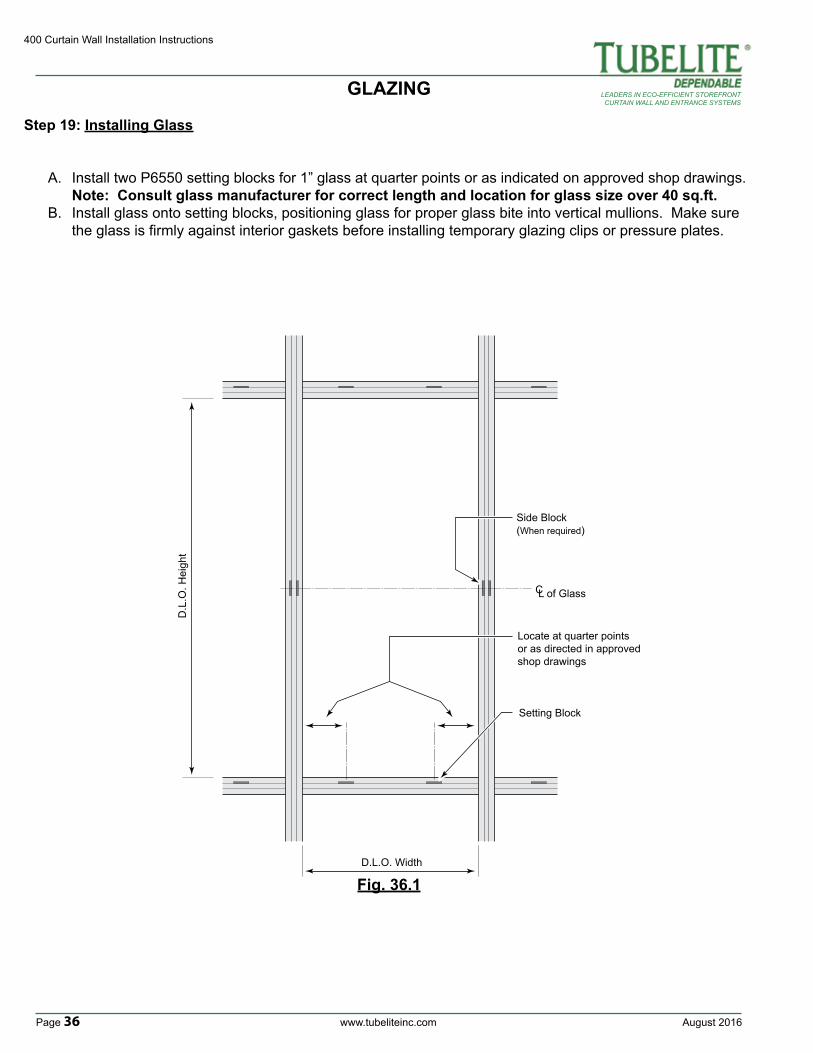
Step 19: Installing Glass
A. Install two P6550 setting blocks for 1” glass at quarter points or as indicated on approved shop drawings. Note: Consult glass manufacturer for correct length and location for glass size over 40 sq.ft.B. Install glass onto setting blocks, positioning glass for proper glass bite into vertical mullions. Make sure the glass is firmly against interior gaskets before installing temporary glazing clips or pressure plates.
GLAZING
D.L.O. Width
D.L
.O. H
eigh
t
Locate at quarter points or as directed in approved shop drawings
Side Block(When required)
Setting Block
C L of Glass
Fig. 36.1
August 2016 www.tubeliteinc.com Page 37
400 Curtain Wall Installation Instructions
LEADERS IN ECO-EFFICIENT STOREFRONTCURTAIN WALL AND ENTRANCE SYSTEMS
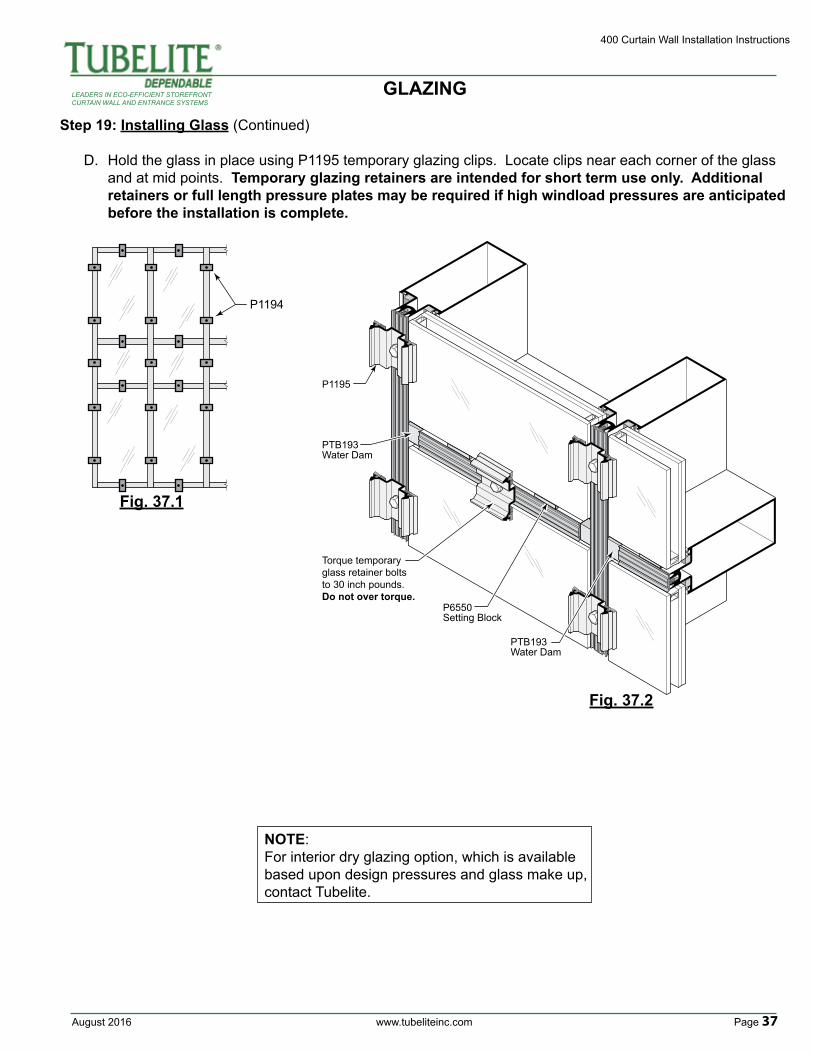
Step 19: Installing Glass (Continued)
D. Hold the glass in place using P1195 temporary glazing clips. Locate clips near each corner of the glass and at mid points. Temporary glazing retainers are intended for short term use only. Additional retainers or full length pressure plates may be required if high windload pressures are anticipated before the installation is complete.
P1194
PTB193Water Dam
PTB193Water Dam
P1195
Torque temporary glass retainer boltsto 30 inch pounds.Do not over torque.
P6550Setting Block
GLAZING
Fig. 37.1
Fig. 37.2
NOTE:For interior dry glazing option, which is available based upon design pressures and glass make up, contact Tubelite.
400 Curtain Wall Installation Instructions
Page 38 www.tubeliteinc.com August 2016
LEADERS IN ECO-EFFICIENT STOREFRONTCURTAIN WALL AND ENTRANCE SYSTEMS
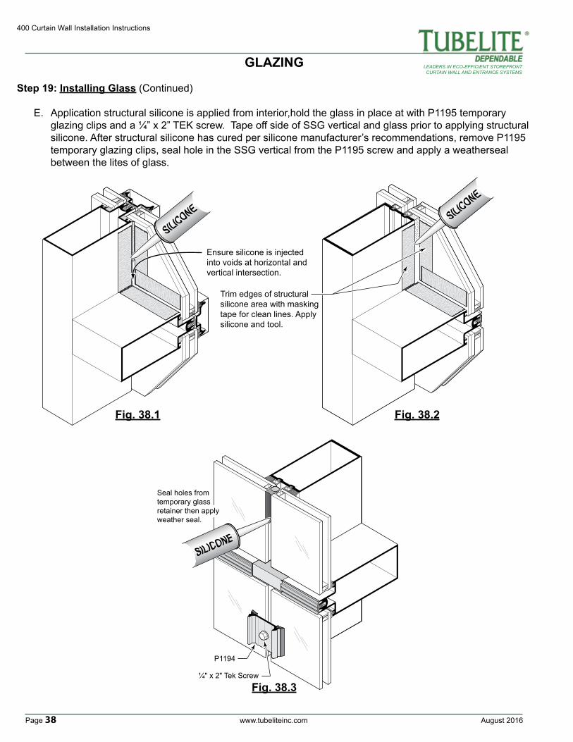
Step 19: Installing Glass (Continued)
E. Application structural silicone is applied from interior,hold the glass in place at with P1195 temporary glazing clips and a ¼” x 2” TEK screw. Tape off side of SSG vertical and glass prior to applying structural silicone. After structural silicone has cured per silicone manufacturer’s recommendations, remove P1195 temporary glazing clips, seal hole in the SSG vertical from the P1195 screw and apply a weatherseal between the lites of glass.
Trim edges of structural silicone area with masking tape for clean lines. Apply silicone and tool.
Ensure silicone is injected into voids at horizontal and vertical intersection.
GLAZING
Fig. 38.1 Fig. 38.2
P1194
¼" x 2" Tek Screw
Seal holes from temporary glass retainer then apply weather seal.
Fig. 38.3
August 2016 www.tubeliteinc.com Page 39
400 Curtain Wall Installation Instructions
LEADERS IN ECO-EFFICIENT STOREFRONTCURTAIN WALL AND ENTRANCE SYSTEMS
Fig. 39.1
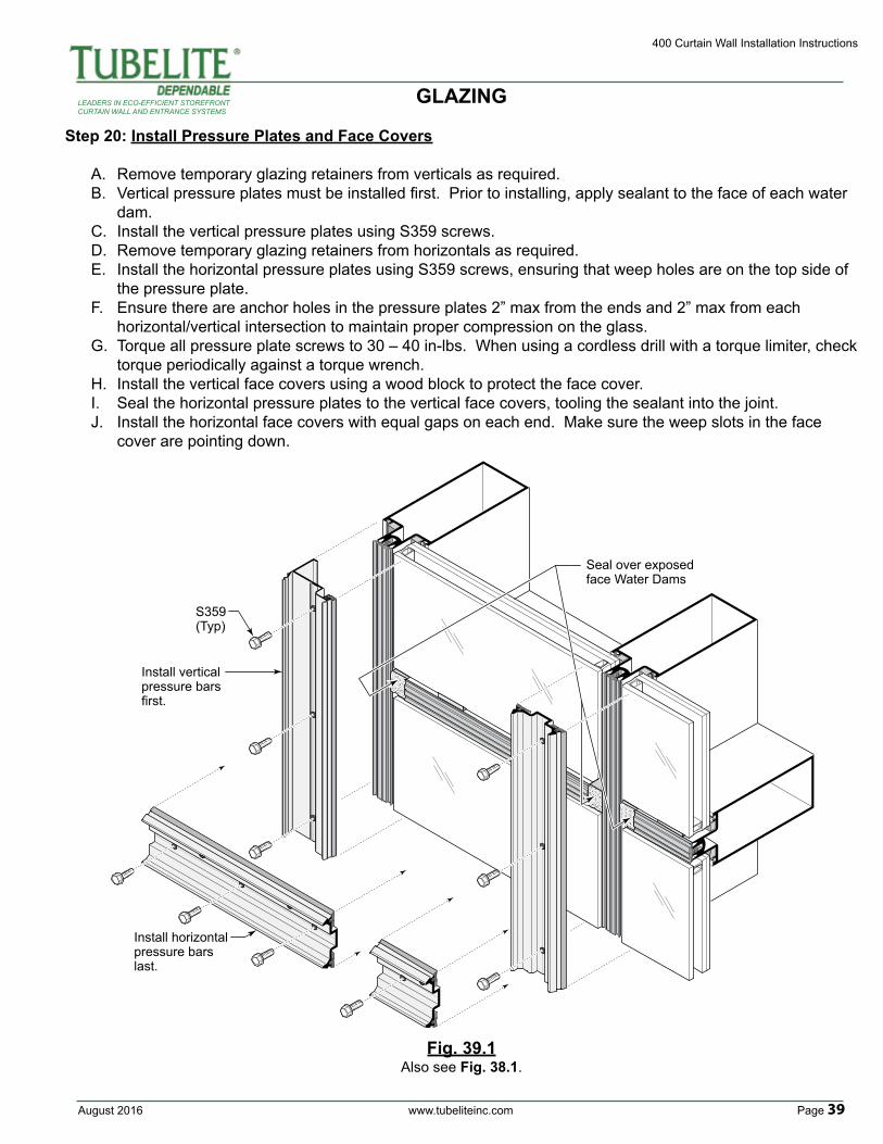
Step 20: Install Pressure Plates and Face Covers
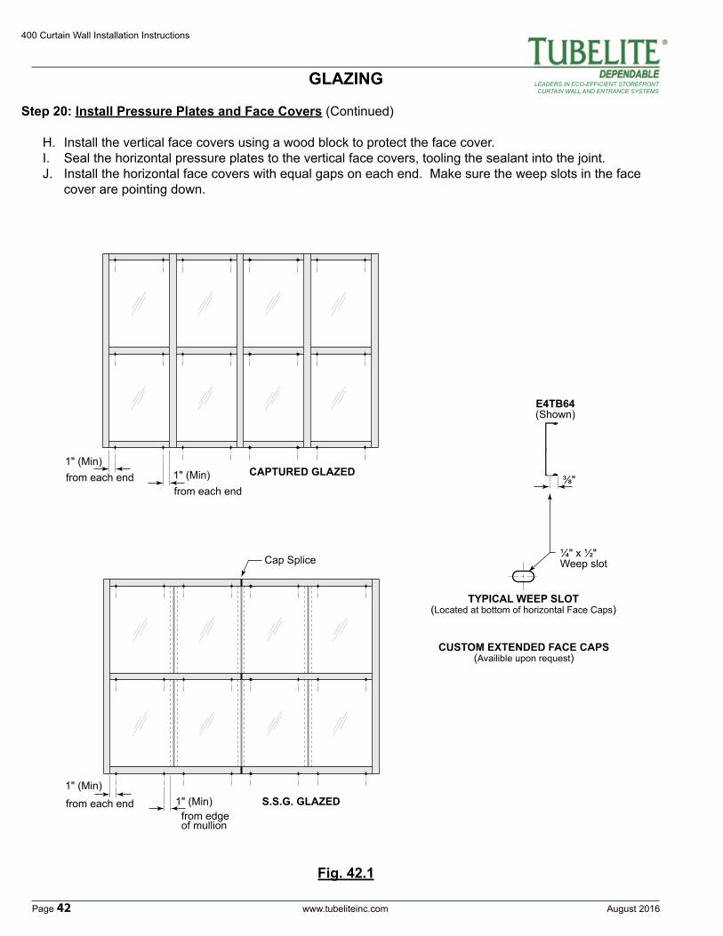
A. Remove temporary glazing retainers from verticals as required.B. Vertical pressure plates must be installed first. Prior to installing, apply sealant to the face of each water dam.C. Install the vertical pressure plates using S359 screws. D. Remove temporary glazing retainers from horizontals as required.E. Install the horizontal pressure plates using S359 screws, ensuring that weep holes are on the top side of the pressure plate.F. Ensure there are anchor holes in the pressure plates 2” max from the ends and 2” max from each horizontal/vertical intersection to maintain proper compression on the glass.G. Torque all pressure plate screws to 30 – 40 in-lbs. When using a cordless drill with a torque limiter, check torque periodically against a torque wrench.H. Install the vertical face covers using a wood block to protect the face cover.I. Seal the horizontal pressure plates to the vertical face covers, tooling the sealant into the joint.J. Install the horizontal face covers with equal gaps on each end. Make sure the weep slots in the face cover are pointing down.
Seal over exposed face Water Dams
Install vertical pressure bars first.
S359(Typ)
Install horizontal pressure bars last.
Also see Fig. 38.1.
GLAZING
400 Curtain Wall Installation Instructions
Page 40 www.tubeliteinc.com August 2016
LEADERS IN ECO-EFFICIENT STOREFRONTCURTAIN WALL AND ENTRANCE SYSTEMS
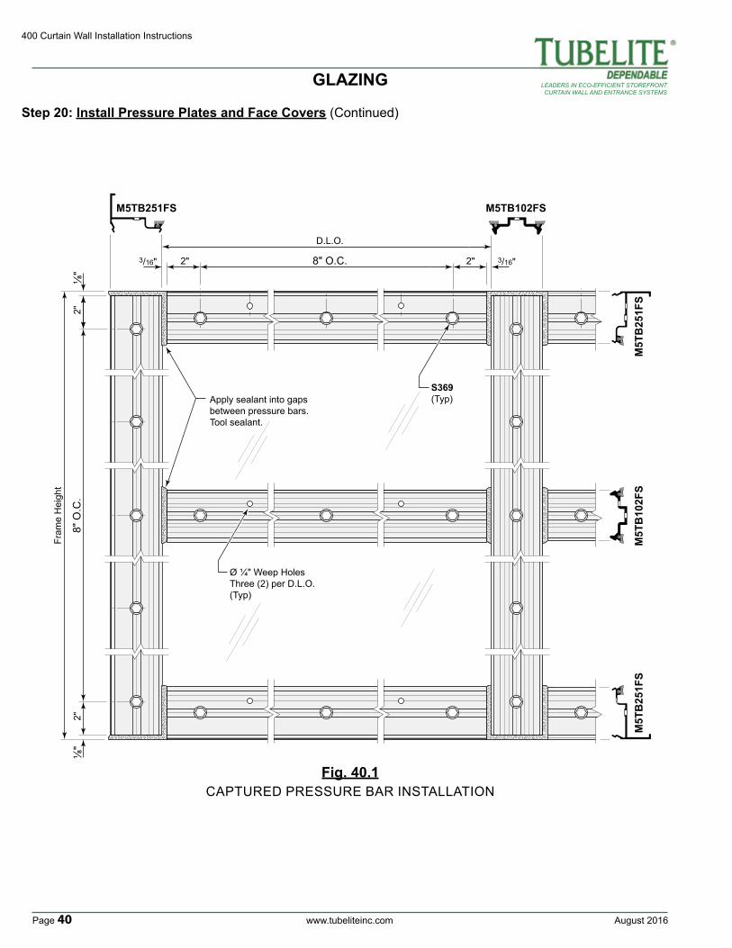
Apply sealant into gaps between pressure bars.Tool sealant.
S369(Typ)
M5TB251FS M5TB102FS
Fram
e H
eigh
t
8" O
.C.
⅛"
⅛"
3/16"
D.L.O.
8" O.C.3/16"
Ø ¼" Weep HolesThree (2) per D.L.O.(Typ)
M5T
B25
1FS
M5T
B10
2FS
M5T
B25
1FS
2"2"
2" 2"
Fig. 40.1
Step 20: Install Pressure Plates and Face Covers (Continued)
CAPTURED PRESSURE BAR INSTALLATION
GLAZING
August 2016 www.tubeliteinc.com Page 41
400 Curtain Wall Installation Instructions
LEADERS IN ECO-EFFICIENT STOREFRONTCURTAIN WALL AND ENTRANCE SYSTEMS
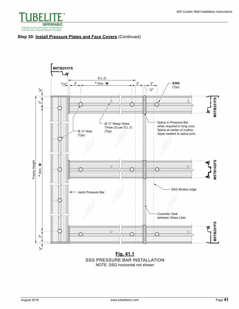
Fig. 41.1
Step 20: Install Pressure Plates and Face Covers (Continued)
SSG PRESSURE BAR INSTALLATIONNOTE: SSG horizontal not shown
Fram
e H
eigh
t
⅛"
⅛"
* Dim
. 'A
'2"
2"
3/16" 2"
½"
2"2"
D.L.O.
* Dim. 'A'
Cosmetic Seal between Glass Lites
Ø ¼" Hole(Typ)
Jamb Pressure BarSSG Mullion edge
Splice in Pressure Barwhen required in long runs.Splice at center of mullion.Apply sealant to splice joint.
S369(Typ)
Ø ¼" Weep HolesThree (3) per D.L.O.(Typ)
M5T
B25
1FS
M5TB251FS
M5T
B25
1FS
M5T
B10
2FS
400 Curtain Wall Installation Instructions
Page 42 www.tubeliteinc.com August 2016
LEADERS IN ECO-EFFICIENT STOREFRONTCURTAIN WALL AND ENTRANCE SYSTEMS
1" (Min)
from each end
1" (Min)from each end 1" (Min)
from each end
1" (Min)from edge of mullion
TYPICAL WEEP SLOT(Located at bottom of horizontal Face Caps)
CAPTURED GLAZED
S.S.G. GLAZED
¼" x ½" Weep slotCap Splice
E4TB64(Shown)
⅜"
CUSTOM EXTENDED FACE CAPS(Availible upon request)
Step 20: Install Pressure Plates and Face Covers (Continued)
H. Install the vertical face covers using a wood block to protect the face cover.I. Seal the horizontal pressure plates to the vertical face covers, tooling the sealant into the joint.J. Install the horizontal face covers with equal gaps on each end. Make sure the weep slots in the face cover are pointing down.
Fig. 42.1
GLAZING
August 2016 www.tubeliteinc.com Page 43
400 Curtain Wall Installation Instructions
LEADERS IN ECO-EFFICIENT STOREFRONTCURTAIN WALL AND ENTRANCE SYSTEMS
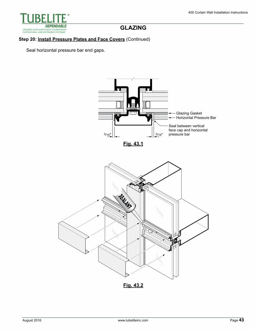
Step 20: Install Pressure Plates and Face Covers (Continued)
Seal horizontal pressure bar end gaps.
Fig. 43.1
3/16" 3/16"
Horizontal Pressure Bar
Seal between vertical face cap and horizontal pressure bar
Glazing Gasket
Fig. 43.2
GLAZING
400 Curtain Wall Installation Instructions
Page 44 www.tubeliteinc.com August 2016
LEADERS IN ECO-EFFICIENT STOREFRONTCURTAIN WALL AND ENTRANCE SYSTEMS
Glazing gaskets and glass not shown for clarity.
Fig. 44.2
½"
½"
½"
2"2"
5"
C Lof mullion
splice
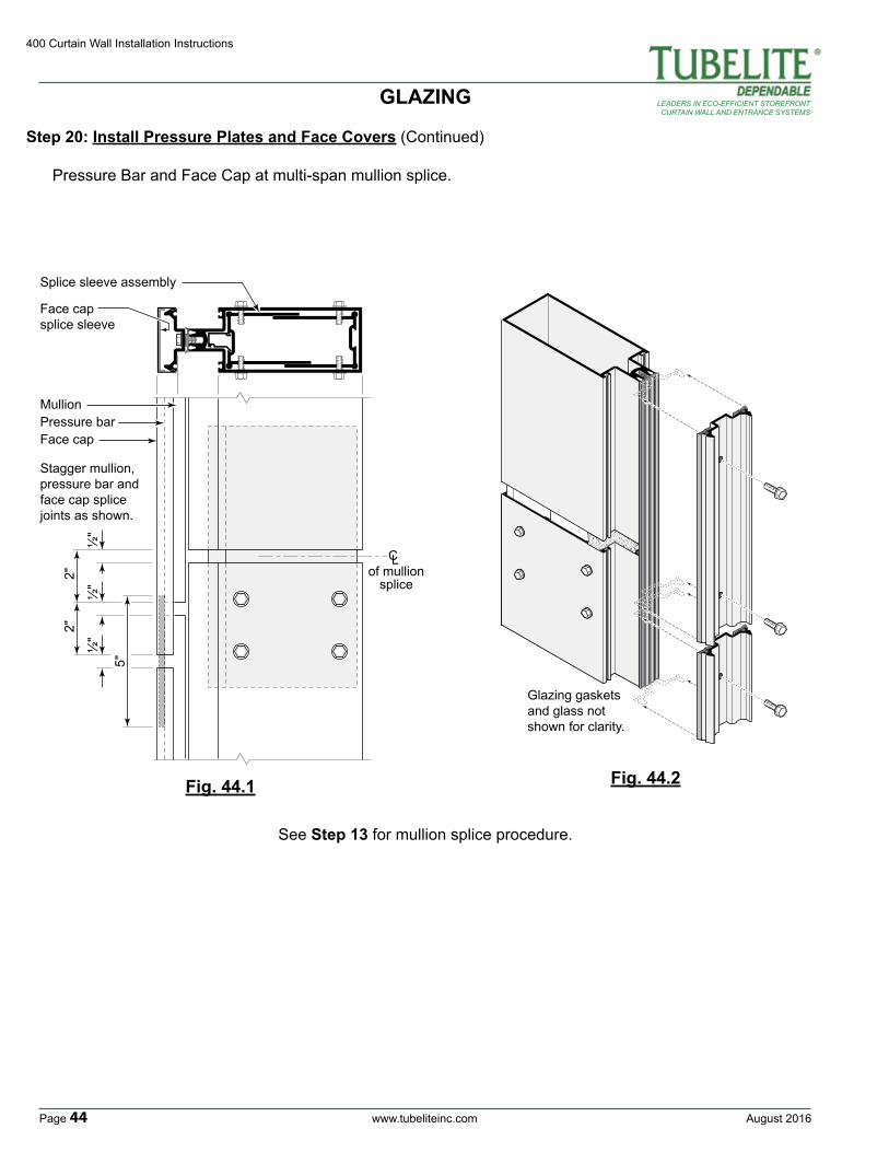
Stagger mullion, pressure bar and face cap splice joints as shown.
MullionPressure barFace cap
Splice sleeve assembly
Face cap splice sleeve
Fig. 44.1
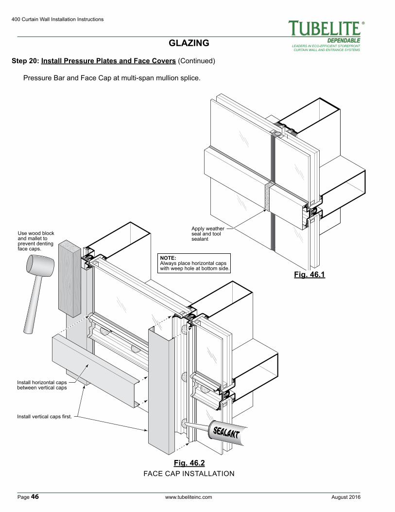
Step 20: Install Pressure Plates and Face Covers (Continued)
Pressure Bar and Face Cap at multi-span mullion splice.
See Step 13 for mullion splice procedure.
GLAZING
August 2016 www.tubeliteinc.com Page 45
400 Curtain Wall Installation Instructions
LEADERS IN ECO-EFFICIENT STOREFRONTCURTAIN WALL AND ENTRANCE SYSTEMS
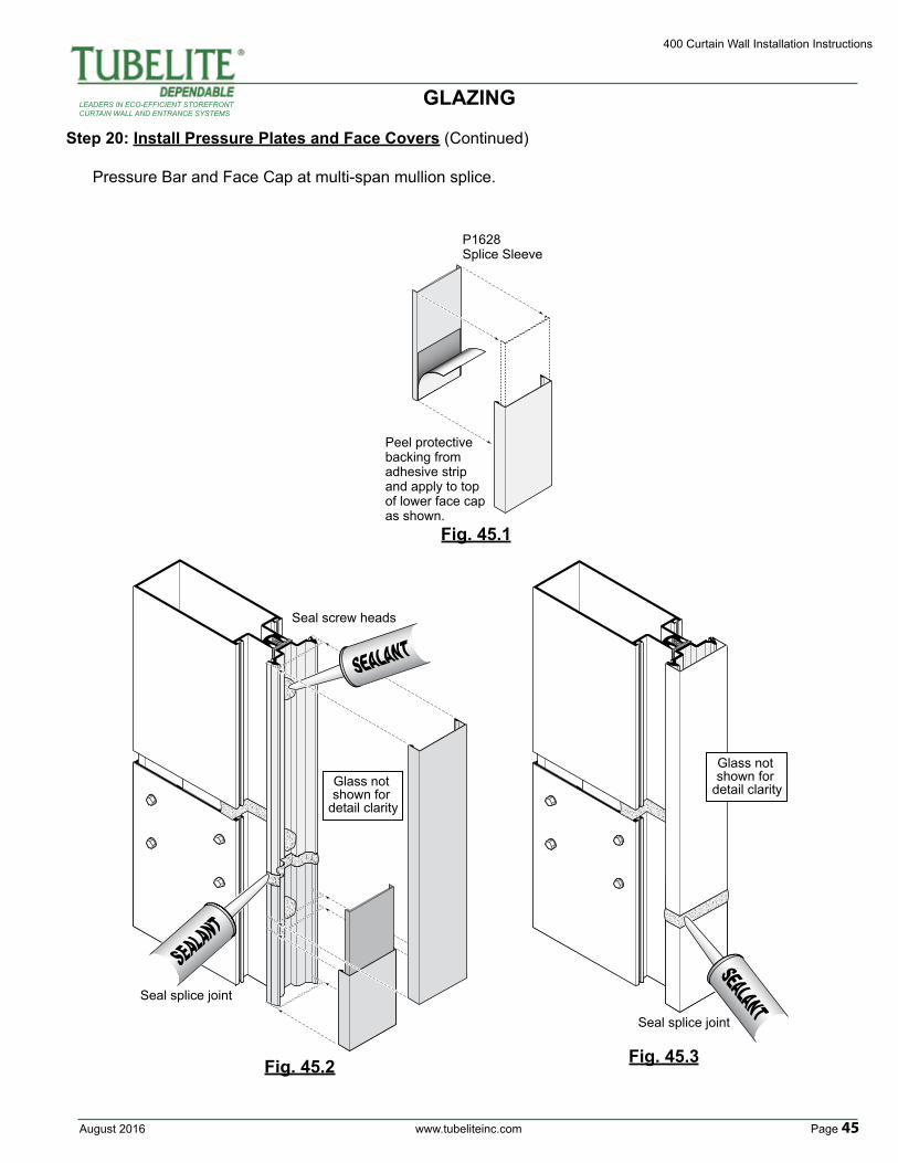
Step 20: Install Pressure Plates and Face Covers (Continued)
Pressure Bar and Face Cap at multi-span mullion splice.
P1628Splice Sleeve
Peel protective backing from adhesive strip and apply to top of lower face cap as shown.
Seal screw heads
Seal splice joint
Glass not shown for
detail clarity
Seal splice joint
Glass not shown for
detail clarity
Fig. 45.2 Fig. 45.3
Fig. 45.1
GLAZING
400 Curtain Wall Installation Instructions
Page 46 www.tubeliteinc.com August 2016
LEADERS IN ECO-EFFICIENT STOREFRONTCURTAIN WALL AND ENTRANCE SYSTEMS
NOTE:Always place horizontal caps with weep hole at bottom side.
Install horizontal capsbetween vertical caps
Install vertical caps first.
Use wood block and mallet to prevent denting face caps.
Fig. 46.2
Fig. 46.1
FACE CAP INSTALLATION
Step 20: Install Pressure Plates and Face Covers (Continued)
Pressure Bar and Face Cap at multi-span mullion splice.
GLAZING
Apply weather seal and tool sealant

August 2016 www.tubeliteinc.com Page 47
400 Curtain Wall Installation Instructions
LEADERS IN ECO-EFFICIENT STOREFRONTCURTAIN WALL AND ENTRANCE SYSTEMS
ENTRANCE FRAMING
A. All door framing is shipped fabricated from the factory. Curtain wall frames can be installed in the field prior to installing the doors. B. Curtain wall verticals and door subframes run to floor. Bed verticals in sealant and anchor to building per approved shop drawings. See Fig. 47.1 and Fig. 47.2 for possible anchoring methods. Always refer to approved shop drawings for specific requirements.
Mullion at door jamb runs through to substrate.Apply sealant around base of mullion and tool prior to subframe installation.
Sealant to fully cover door frame jamb area.FOOT PRINT of
DOORFRAMEand
THRESHOLD
E3550
Apply liberal amount of sealant at interior and exterior of threshold.
Fig. 47.2Fig. 47.3
ENTRANCE FRAMING
1¾"
¾"
¾"
EQ
.E
Q.
PTB22PTB22
Fig. 47.1
400 Curtain Wall Installation Instructions
Page 48 www.tubeliteinc.com August 2016
LEADERS IN ECO-EFFICIENT STOREFRONTCURTAIN WALL AND ENTRANCE SYSTEMS
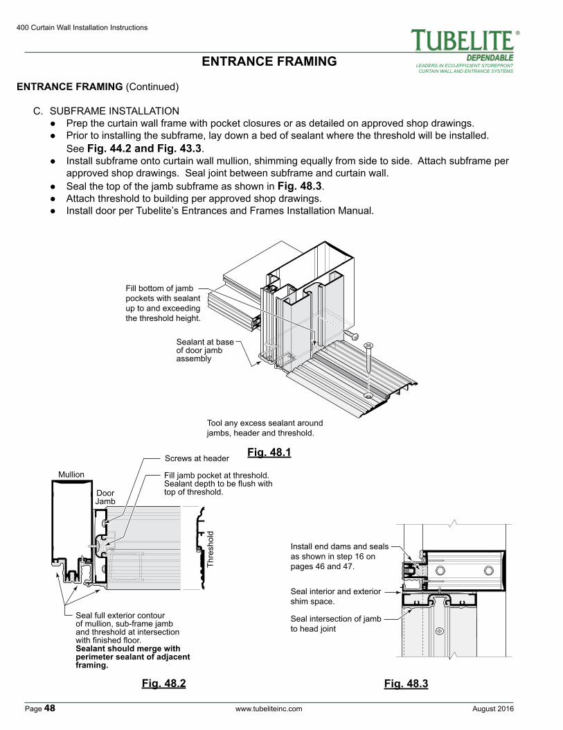
ENTRANCE FRAMING (Continued)
C. SUBFRAME INSTALLATION ● Prep the curtain wall frame with pocket closures or as detailed on approved shop drawings. ● Prior to installing the subframe, lay down a bed of sealant where the threshold will be installed. See Fig. 44.2 and Fig. 43.3. ● Install subframe onto curtain wall mullion, shimming equally from side to side. Attach subframe per approved shop drawings. Seal joint between subframe and curtain wall. ● Seal the top of the jamb subframe as shown in Fig. 48.3. ● Attach threshold to building per approved shop drawings. ● Install door per Tubelite’s Entrances and Frames Installation Manual.
Tool any excess sealant around jambs, header and threshold.
Fill bottom of jamb pockets with sealant up to and exceeding the threshold height.
Sealant at base of door jamb assembly
DoorJamb
Mullion
Thre
shol
d
Seal full exterior contour of mullion, sub-frame jamb and threshold at intersection with finished floor.Sealant should merge with perimeter sealant of adjacent framing.
Fill jamb pocket at threshold. Sealant depth to be flush with top of threshold.
Screws at header Fig. 48.1
Fig. 48.2 Fig. 48.3
ENTRANCE FRAMING
Install end dams and seals as shown in step 16 on pages 46 and 47.
Seal interior and exterior shim space.
Seal intersection of jamb to head joint
August 2016 www.tubeliteinc.com Page 49
400 Curtain Wall Installation Instructions
LEADERS IN ECO-EFFICIENT STOREFRONTCURTAIN WALL AND ENTRANCE SYSTEMS
REGLAZING
A. Reglazing is done from the exterior.B. Carefully remove face covers surrounding the lite to be removed.C. Remove vertical and horizontal pressure plates adjacent to affected lite.D. Temp surrounding glass in place with P1195 temporary clips per Step 19, pages 46 through 48.E. Remove lite of glass and gaskets from opening. Clean debris and sealant from the glass pocket and glazing reglets.F. Install new glass in opening per Steps 17 through 19, pages 32 through 40.
REGLAZING
400 Curtain Wall Installation Instructions
Page 50 www.tubeliteinc.com August 2016
LEADERS IN ECO-EFFICIENT STOREFRONTCURTAIN WALL AND ENTRANCE SYSTEMS
CORNER CONDITION
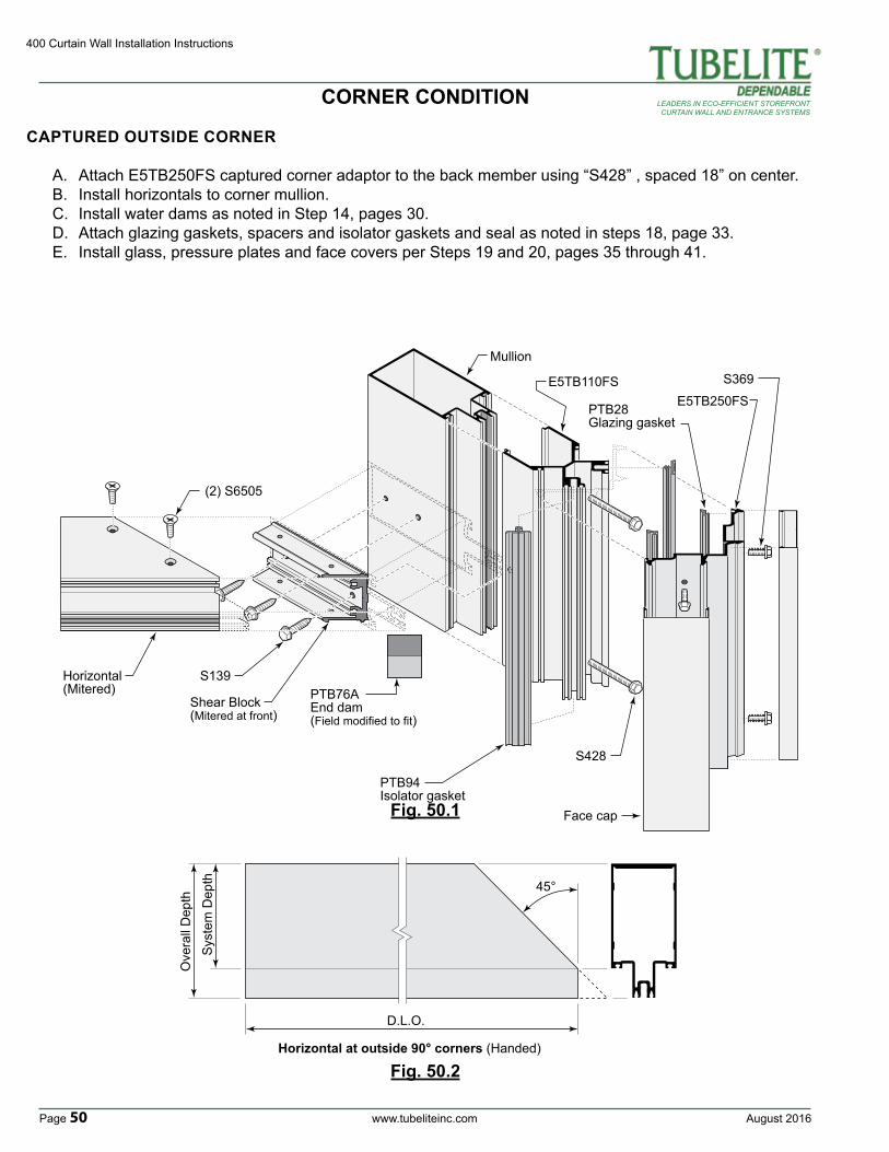
CAPTURED OUTSIDE CORNER
A. Attach E5TB250FS captured corner adaptor to the back member using “S428” , spaced 18” on center.B. Install horizontals to corner mullion.C. Install water dams as noted in Step 14, pages 30.D. Attach glazing gaskets, spacers and isolator gaskets and seal as noted in steps 18, page 33.E. Install glass, pressure plates and face covers per Steps 19 and 20, pages 35 through 41.
Horizontal(Mitered)
Shear Block(Mitered at front)
S139
(2) S6505
S428
PTB28Glazing gasket
PTB94Isolator gasket
E5TB110FSE5TB250FS
Mullion
S369
PTB76AEnd dam(Field modified to fit)
Face cap
D.L.O.
45°
Sys
tem
Dep
th
Ove
rall
Dep
th
Horizontal at outside 90° corners (Handed)
Fig. 50.1
Fig. 50.2
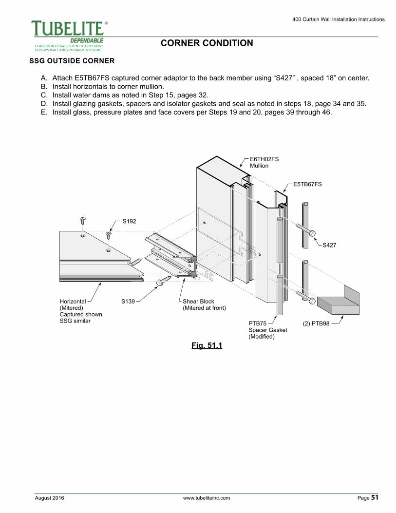
August 2016 www.tubeliteinc.com Page 51
400 Curtain Wall Installation Instructions
LEADERS IN ECO-EFFICIENT STOREFRONTCURTAIN WALL AND ENTRANCE SYSTEMS
Fig. 51.1
Horizontal(Mitered)Captured shown,SSG similar
Shear Block(Mitered at front)
S139
S192
(2) PTB98PTB75Spacer Gasket(Modified)
S427
E5TB67FS
E6TH02FSMullion
CORNER CONDITION
SSG OUTSIDE CORNER
A. Attach E5TB67FS captured corner adaptor to the back member using “S427” , spaced 18” on center.B. Install horizontals to corner mullion.C. Install water dams as noted in Step 15, pages 32.D. Install glazing gaskets, spacers and isolator gaskets and seal as noted in steps 18, page 34 and 35.E. Install glass, pressure plates and face covers per Steps 19 and 20, pages 39 through 46.