Embed Size (px)
Citation preview

WORK SAFELY! For maximum safety, perform this installation on a clean, level surface and with the engine turned off. Place blocks or wedges in front of and behind both rear wheels to prevent movement in either direction. CAUTION: To avoid any possibility of bodily injury or damage to vehicle, do not attempt installation until you are confident that the vehicle is safely secured and will not move.
WARNING: Incorrect checkball placement can result in serious transmission damage. Be sure to follow the instructions carefully. We recommend that you read through the instructions completely before beginning the installation and familiarize yourself with the installation procedure and tools required. Check the tool list at the end of these instructions for the tools required to install your B&M Chrysler TorqueFlite Shift Improver Kit.
NOTE: The B&M Chrysler TorqueFlite Shift Improver Kit is not a cure-all for an ailing transmission. If your transmission is slipping or in poor general shape, the installation of this Shift Improver Kit may worsen the condition. However, on a properly operating transmission in average condition, the Shift Improver Kit will provide the kind of transmission performance you're looking for. When installing your Shift Improver Kit there are several other B&M products you may wish to consider: Transmission Oil Cooler - We feel that it is very important that every vehicle used in a heavy duty application (racing, towing, RV, etc.) should have an oil cooler. Heat is the major cause of transmission failures, and an oil cooler is an inexpensive safeguard against overheating and failure. B&M offers a wide range of transmission coolers to suit every need, which are available at your B&M dealer. Trick Shift Performance ATF – Trick Shift performance automatic transmission fluid is the industry’s leading performance ATF. A specially blended oil with foam inhibitors, extreme pressure agents and shift improvers, this fluid assures protection while delivering the fastest possible shifts. You literally “Pour in performance.” TORQUEFLITE INTRODUCTION NOTE: Transmission components and valves are precision fit parts. Burrs and dirt are the number one enemies of an automatic transmission. Cleanliness is very important, so a clean work area or bench is necessary. We suggest a clean work bench top from which oil can easily be cleaned or a large piece of cardboard. This kit contains all parts necessary to obtain two levels of performance depending on intended use: Heavy Duty: Towing, campers, motor homes, police, taxi, on and off-road desert vehicles and 4-wheelers. Street/Strip: Dual purpose performance vehicles. Street and strip high performance cars. Technical Support (707) 544‐4761 1 www.HURST‐SHIFTERS.com
Installation Instructions SHIFTER IMPROVER KIT
Fits: Chrysler, Dodge, Plymouth w/Torqueflight 71-77 TF A-727 (All) / 71-77 TF A-904 (8 Cyl)
Catalog # 10225
Autovehioff tvehhave 1. Dallowshoupan and dowis re Techni
2. TFig.BefomusFig.(drivbodandwreremandin logeaseleLet
omatic transicle be allowhe ground icle is firme a small bo
Drain oil panw the fluid uld considebolt one atthe pan wi
wn slightly wemoved the
cal Support (707)
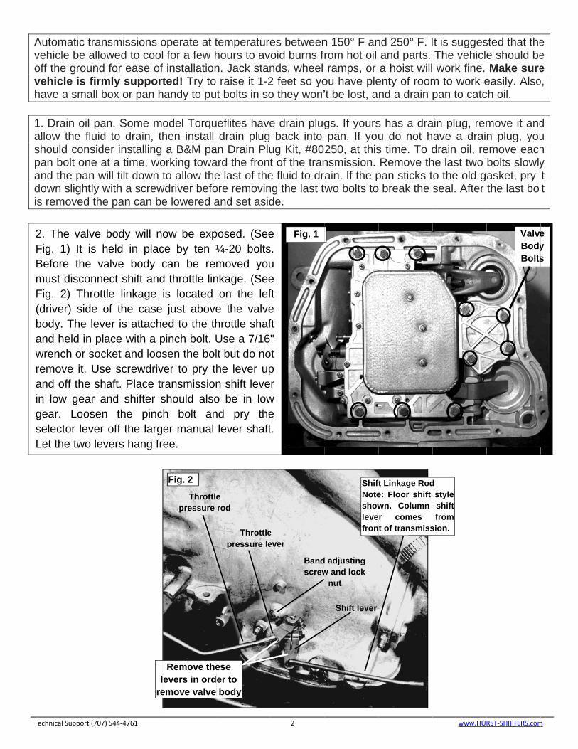
The valve b 1) It is hore the vast disconne 2) Throttlver) side oy. The leve held in planch or sock
move it. Use off the shaow gear anr. Loosen
ector lever the two lev
smissions owed to coolfor ease of
mly supporox or pan h
n. Some mto drain, t
er installing t a time, woll tilt down
with a screw pan can be
544‐4761
body will neld in plac
alve body cect shift ande linkage
of the caseer is attachace with a pket and loose screwdrivaft. Place trnd shifter s
the pincoff the larg
vers hang fr
lre
operate at tl for a few hf installationrted! Try to handy to pu
odel Torquhen install a B&M pa
orking towato allow the
wdriver befoe lowered a
ow be expce by ten ¼can be red throttle linis located just aboveed to the thpinch bolt. Usen the bol
ver to pry thransmissionshould also
ch bolt aner manual
ree.
Throttlepressure
Remove thelevers in ordemove valve
Fig. 2
temperaturehours to avn. Jack stanraise it 1-2t bolts in so
ueflites havedrain plug
an Drain Pluard the fronte last of theore removinand set asid
posed. (See¼-20 boltsmoved younkage. (See
on the lefe the valvehrottle shafUse a 7/16lt but do nohe lever upn shift leveo be in lownd pry thelever shaft
e rod
Throttlepressure le
ese er to body
es betweenoid burns frnds, wheel 2 feet so yoo they won’
e drain plugback into
ug Kit, #80t of the trane fluid to drng the last twde.
2
e s. u e ft e ft "
ot p r
w e t.
Fig. 1
e ever
Bandscrew
n 150° F anrom hot oil ramps, or
ou have ple’t be lost, a
gs. If yourspan. If you250, at thisnsmission. rain. If the pwo bolts to
ShiftNoteshowlevefron
d adjusting w and lock
nut
Shift lever
nd 250° F. Iand parts. a hoist will
enty of roomnd a drain
s has a drau do not hs time. To dRemove th
pan sticks to break the
ft Linkage Rode: Floor shift wn. Column r comes t of transmiss
It is suggesThe vehicle work fine. m to work epan to catc
ain plug, remave a draidrain oil, rehe last two o the old gseal. After
www.HU
d style shift from
sion.
sted that thee should beMake sure
easily. Alsoch oil.
move it andn plug, you
emove eachbolts slowlyasket, pry ithe last bol
RST‐SHIFTERS.com
ValveBodyBolts
e e e
o,
d u h y t t
m
e y s
CAUpresreguconvthrot Techni
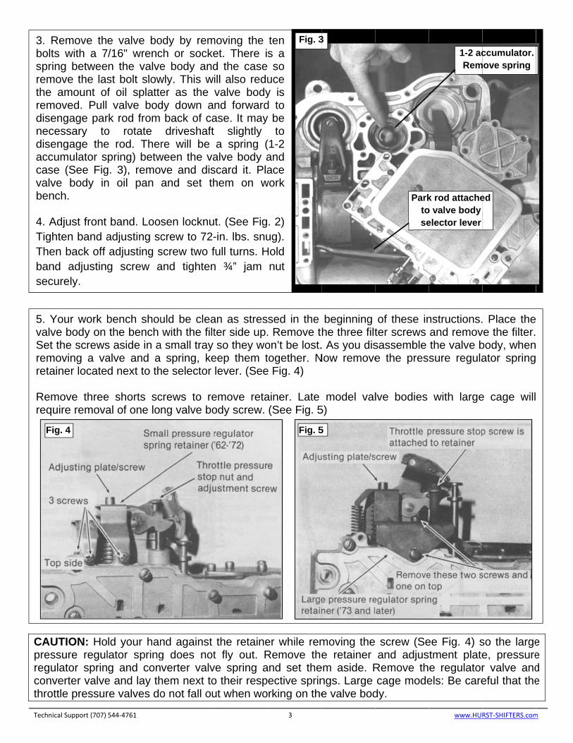
3. Rboltspriremthe remdisenecdiseacccasvalvben 4. ATighThebansec
5. YvalvSet remreta Remrequ
Fi
UTION: Hossure regululator sprinverter valvettle pressur
cal Support (707)
Remove thts with a 7ng betwee
move the lasamount of
moved. Pullengage parcessary toengage theumulator se (See Fig
ve body innch.
Adjust front hten band aen back off nd adjustinurely.
Your work bve body on the screws
moving a vaainer locate
move threeuire remova
ig. 4
ld your hanlator springg and con
e and lay thre valves do
544‐4761
e valve bo7/16" wrencn the valvest bolt slowf oil splattevalve bod
rk rod from o rotate e rod. Therpring) betw
g. 3), remon oil pan
band. Looadjusting scadjusting sg screw a
bench shouthe bench
s aside in aalve and a d next to th
e shorts scal of one lo
nd against g does notverter valv
hem next too not fall ou
ody by remch or sockee body and
wly. This wier as the dy down a
back of cadriveshaft
re will be ween the vave and disand set th
sen locknucrew to 72-screw two fand tighten
uld be cleawith the filt
a small tray spring, ke
he selector
crews to reng valve bo
the retainet fly out. R
ve spring ao their resput when wo
moving the et. There isd the case ill also reduvalve bodynd forwardase. It may
slightly a spring (
alve body ascard it. Plahem on w
t. (See Fig-in. lbs. snufull turns. Hn ¾” jam
an as strester side up.so they wo
eep them tlever. (See
emove retaody screw.
er while remRemove theand set theective sprinrking on the
3
ten s a so
uce y is d to be
to 1-2 and ace
work
. 2) ug).
Hold nut
Fig. 3
sed in the . Remove ton’t be lost.ogether. N
e Fig. 4)
ainer. Late (See Fig. 5
Fig. 5
moving thee retainer
em aside. Rngs. Large e valve bod
3
beginning he three filt. As you dis
Now remove
model val5)
5
screw (Seand adjus
Remove thcage mode
dy.
Parktose
of these inter screws sassemble e the pres
lve bodies
ee Fig. 4) stment platee regulatorels: Be care
www.HU
1-2 acRem
k rod attacheo valve body elector lever
nstructions.and removthe valve bsure regula
with large
so the largee, pressurer valve andeful that the
RST‐SHIFTERS.com
ccumulator. move spring
ed
. Place theve the filter.body, whenator spring
e cage will
e e d e
m
6. Sleft refea se
Techni
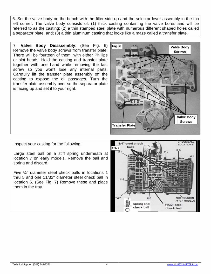
7. RemTheor stogescreCarcasttranis fa
Insp Larglocaspri Fivethrulocathem
Set the valvcorner. Thrred to as t
eparator pla
cal Support (707)
Valve Bomove the vaere will be slot heads. ether with ew so yorefully lift tting to ex
nsfer plate aacing up an
pect your ca
ge steel bation 7 on ing and disc
e ¼” diameu 5 and oneation 6. (Sem in the tra
ve body on he valve bothe castingate, and; (3)
544‐4761
ody Disasalve body sfourteen ofHold the one hand
ou won’t lthe transfexpose the assembly o
nd set it to y
asting for th
ball on a searly modcard.
eter steel ce 11/32" diee Fig. 7)
ay.
the bench ody consis; (2) a thin ) a thin alum
ssembly: screws fromf them, withcasting and
while remlose any
er plate asoil passa
over so the your right.
he following
stiff spring els. Remov
check ballsiameter steRemove th
with the filts of: (1) tstamped s
minum cast
(See Figm transfer ph either Phd transfer
moving theinternal p
ssembly offages. Turn
separator
g:
underneatve the ball
s in locatioeel check bhese and p
ter side upthick castinteel plate wting that loo
4
. 6) plate. hillips plate last
parts. f the the plate
Fig.
Tran
th at l and
ons 1 ball in place
Fig. 7
p and the seng containiwith numerooks like a m
6
nsfer Plate
7
elector leveing the valous differen
maze called
er assembllve bores ant shaped ha transfer
www.HU
ValvSc
V
y in the topand will beholes calledplate.
RST‐SHIFTERS.com
ve Body crews
Valve Body Screws
p e d
m

Instavalvprevend you Insta
Techni
Hea Strethe the allowvalvvalv
9. Rvalvyouscreout the 2 shplatthe Grinclea
10. Fig.valvburrasid
all the shutve throttle pvent leaks.
plate. Youcannot hol
all five shor
cal Support (707)
avy Duty: G
eet/Strip: Rgovernor pselector levwing it to f
ve throttle ve throttle p
Remove thve end platr hand on ew so the thand get loskit into the hift control te and cast
valve bodnd the vaarance. Inst
Install pres 10) Instal
ves should rs that mayde.
ttle valve thplug into its Grind the r
u should beld the platert screws fin
544‐4761
Go to Step 9
Remove fivplug and plaver as you fly out of pplug. Rem
plug spring.
hree long ste and smathe end p
hree small st. Install th1-2 shift covalve sprin
ting. The ady casting lve slightlytall three lo
ssure regull the convemove free
y cause stic
hrottle plugbore. The
rod down sle able to hoe flat againsnger tight o
9
ve short scate. (See Fiwill disengaposition. R
move and d
screws andall casting plate while springs undhe ¼” steeontrol valveng. Install t
assembly mwith thum
y, if neceng screws f
lator valve erter valve ely and eakiness or b
g rod supplplug must lightly if necold the platst the slight
only.
crews andig 8) Do noage the detemove the
discard the
d remove t(See Fig. 9removing
derneath dl ball suppl
e bore insidthe limit va
must sit flat mb pressurssary, tofinger tight
into its borinto its bor
asily. Remobinding. Set
ied with thbe flush orcessary to te flat againt spring ten
5
remove ot rotate tent ball
e shuttle shuttle
the limit 9). Hold the last o not fly lied with
de the 1-alve end
against re only. provide only.
re. (See re. Both ove any t casting
he kit into tr slightly beprovide cle
nst the casnsion of the
Fig. 9
he valve below the suearance. Inssting with the shift valve
ore. Install urface of thestall the gohumb presses, the rod
www.HU
the shuttlee casting to
overnor plugsure only. Iis too long
RST‐SHIFTERS.com
Fig. 8
Fig. 1
e o g f .
m
0

12. L All MInstaHeaStre Alignfourtreguplateretawithscre
Techni
11. asseplateNote11) sepatype Wasrembensepaandreta
13. casTighpresuntiadjucheshoscre NOTmod
Lay casting
Models: all one 11/3
avy Duty: Fieet/Strip: Fo
n transfer pteen screw
ulator springe into placiner. Engag prong in
ews finger ti
cal Support (707)
Place trembly in fre will be he how your
Remove arator platee filter in yo
sh the transmove any di
ch with tarator plate align the s
aining screw
Tighten fouting on thehten all essure reguil the distusting scre
eck this meort retainingews should
TE: Adjusdels.
g in front of
32" diameteve ¼” steel
our ¼” steel
plate assemws in placeg and conve in retainge pressurretainer. Hight. (See F
544‐4761
ransfer plaront of youheld on withr stiffener p
the retaine off. If theur transfer
sfer plate inirt. Lay the he passage in positionscrew hole
ws and tight
urteen scree bottom ofnd plate s
ulator sprinance fromw is 1-7/8"asurement
g screws to be tight.
tments are
you and in
er check bal balls in locl balls in loc
mbly over ce finger tighverter valveing cage. A
re regulatorold retaine
Fig. 4)
ate and u. The thin h four or fi
plate is posning screwre is a cheplate, disca
n solvent ortransfer pl
ges facingn on top of s. Install stten screws
ews attachinf the valve screws to g retainer
m the man". Use the . (See Fig.o 35in. lbs
e the sam
stall steel C
all in locatiocations 1 thcations 1,2,
casting andht. (Note: T spring in pAdjusting pr spring witer against v
separator metal sep
ve short scitioned. (Sews and lieck ball or sard it.
r brake clealate down o up. Lay the transfetiffener platfinger tight
ng transfer body to 335in. lbs.from side
nual valve gauge sup 12) Tighte
s. At this p
me for larg
Checkballs
n 6. hru 5 ,3, & 5.
d hold the Three long place. (Seeplate is a cth adjustingvalve body
6
plate parator crews. ee Fig. ft the screen
aner to on the
B&M r plate te and t.
Fi
plate to 5in. lbs. Adjust to side to the
pplied to en three point all
ge cage
as follows:
two halves screws ar
e Fig. 10) Inclose fit whg plate and
y, align scre
ig. 11
Fig. 12
(See Fig. 7
s together wre for the fnsert pressuhen properd engage cew holes a
7)
with your hfilter.) Instaure regulatorly installedconverter vand install
www.HU
hand. Instaall pressureor adjustingd inside thevalve springthree shor
RST‐SHIFTERS.com
ll e g e g rt
m
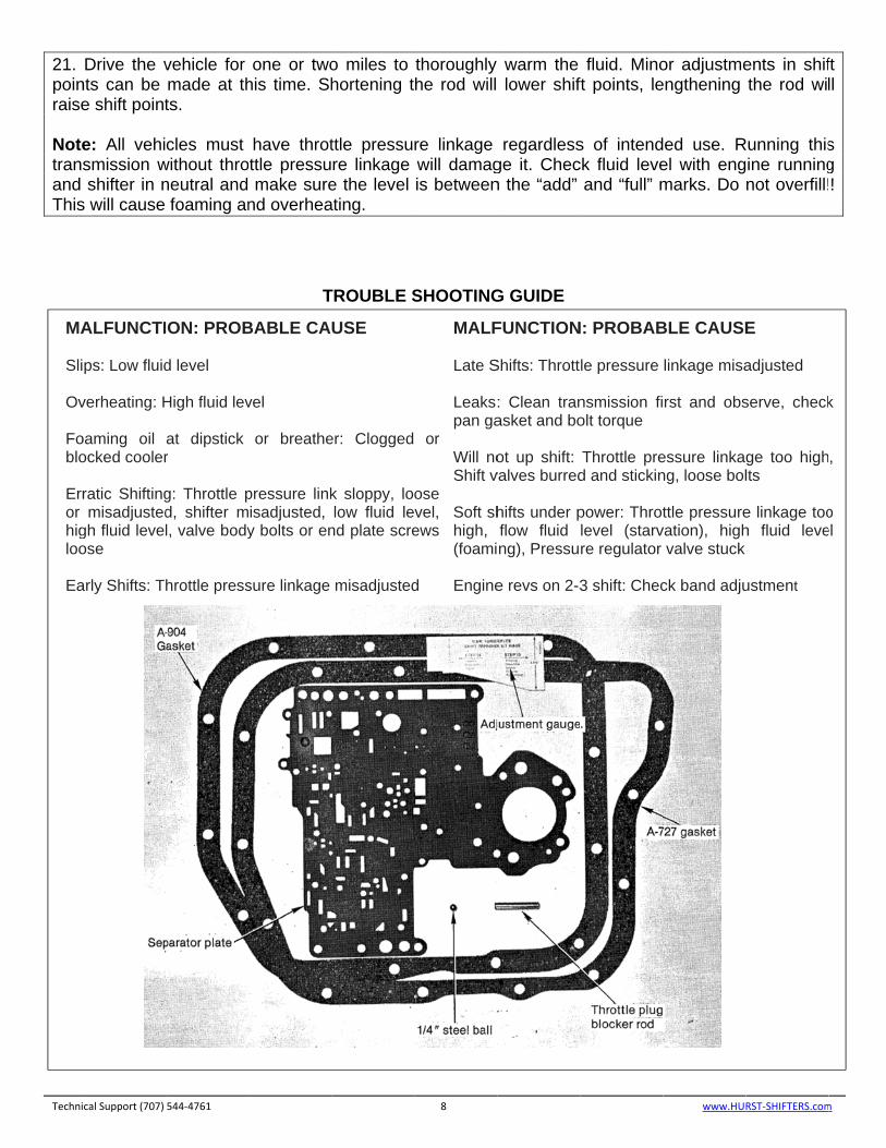
14. insidadju Hea Stre Inspreco
16. throt 17. C150- 18. (whiTighthe posi 19. Tposiforwcarb 20. Trickand engitransthe “
Techni
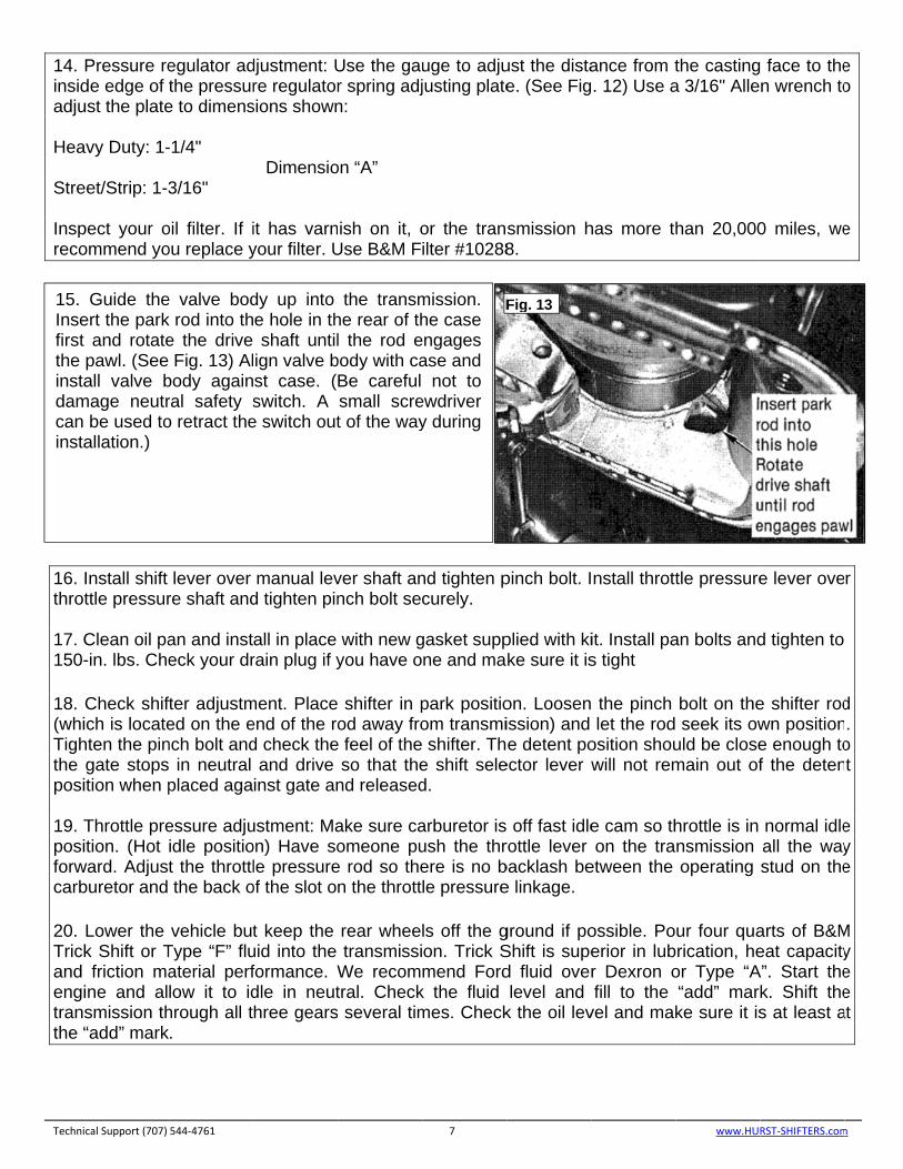
15. Insefirst the instadamcan insta
Pressure rede edge of ust the plate
avy Duty: 1-
eet/Strip: 1-3
pect your oommend yo
Install shift ttle pressur
Clean oil pa-in. lbs. Che
Check shifich is locatehten the pingate stopsition when p
Throttle preition. (Hot
ward. Adjustburetor and
Lower the k Shift or Tfriction ma
ine and alsmission th“add” mark
cal Support (707)
Guide theert the park
and rotatepawl. (See all valve b
mage neutrbe used to
allation.)
egulator adthe pressur
e to dimens
-1/4"
3/16"
oil filter. If iou replace y
lever over re shaft and
an and insteck your dr
fter adjustmed on the ench bolt and in neutral placed aga
essure adjuidle positiot the throttlthe back o
vehicle butType “F” fluaterial perflow it to idhrough all t.
544‐4761
e valve bodk rod into the the drive Fig. 13) Al
body againral safety so retract the
djustment: Ure regulator
sions shown
Dimensio
it has varnyour filter. U
manual levd tighten pin
all in place rain plug if y
ment. Placeend of the rod check the
and drive inst gate an
ustment: Maon) Have sole pressure
of the slot o
t keep the uid into the formance. Wdle in neuthree gears
dy up into e hole in thshaft until
ign valve bst case. (switch. A
e switch out
Use the gaur spring adjn:
on “A”
ish on it, oUse B&M F
ver shaft annch bolt sec
with new gyou have o
shifter in pod away fro
e feel of theso that the
nd released
ake sure caomeone pu
e rod so then the thrott
rear wheetransmissi
We recomtral. Check several tim
the transmhe rear of thl the rod e
body with caBe careful small scret of the way
uge to adjujusting plate
or the tranilter #10288
nd tighten pcurely.
gasket suppne and ma
park positioom transmi shifter. The shift seled.
arburetor is ush the threre is no ble pressure
ls off the gon. Trick Smend Ford
k the fluid mes. Check
7
mission. he case
engages ase and
not to ewdriver y during
F
ust the distae. (See Fig
smission h8.
pinch bolt. I
plied with kike sure it is
on. Loosenission) ande detent po
ector lever w
off fast idlerottle lever backlash bee linkage.
ground if poShift is suped fluid overlevel and
k the oil lev
Fig. 13
ance from t. 12) Use a
has more th
nstall thrott
it. Install pas tight
the pinch let the rod
osition shouwill not rem
e cam so thon the tra
etween the
ossible. Poerior in lubr Dexron ofill to the
vel and mak
the castinga 3/16" Alle
han 20,000
tle pressure
an bolts and
bolt on the seek its owuld be closemain out of
hrottle is in nsmission operating
ur four quarication, he
or Type “A“add” marke sure it is
www.HU
face to then wrench to
0 miles, we
e lever ove
d tighten to
e shifter rodwn positione enough tof the deten
normal idleall the waystud on the
arts of B&Meat capacity
A”. Start thek. Shift thes at least a
RST‐SHIFTERS.com
e o
e
r
d . o t
e y e
M y e e
at
m
21. poinraise Notetransand This
Techni
MA Sli Ov Foblo Error higloo Ea
Drive the vnts can be e shift point
e: All vehismission wshifter in n
s will cause
cal Support (707)
ALFUNCTI
ps: Low fluid
verheating: H
oaming oil ocked cooler
ratic Shiftingmisadjusted
gh fluid levelose
arly Shifts: T
vehicle for made at thts.
cles must without throneutral and
foaming an
544‐4761
ION: PROB
d level
High fluid lev
at dipstick r
g: Throttle pd, shifter ml, valve body
hrottle press
one or twohis time. Sh
have throtottle pressu
make surend overhea
T
BABLE CA
vel
or breathe
pressure linkisadjusted, y bolts or en
sure linkage
o miles tohortening t
ttle pressure linkage e the level ating.
TROUBLE S
USE
er: Clogged
k sloppy, lolow fluid le
nd plate scre
misadjusted
thoroughly he rod will
re linkage will damagis between
SHOOTING
8
or
ose vel, ews
d
MALF Late S Leakspan ga Will noShift v Soft shhigh, (foami Engine
warm the lower shif
regardlessge it. Checn the “add”
G GUIDE
FUNCTION
Shifts: Thrott
: Clean tranasket and bo
ot up shift: valves burred
hifts under pflow fluid ng), Pressu
e revs on 2-3
fluid. Minoft points, le
s of intendck fluid leve
and “full” m
N: PROBAB
le pressure
nsmission fiolt torque
Throttle pred and stickin
power: Throtlevel (starvre regulator
3 shift: Chec
or adjustmeengthening
ed use. Rel with engmarks. Do
www.HU
BLE CAUSE
linkage misa
rst and obs
essure linkagng, loose bol
ttle pressurevation), high
valve stuck
ck band adju
ents in shifthe rod wi
Running thisine runningnot overfill!
RST‐SHIFTERS.com
E
adjusted
serve, check
ge too highlts
e linkage tooh fluid leve
ustment
ft ll
s g !
m
k
,
oel

IMPORTANT: RETAIN THESE INSTRUCTIONS FOR FUTURE REFERENCE Technical Service
A highly trained technical service department is maintained by Hurst Performance to answer your technical questions, provide additional product information and offer various recommendations.
Technical service calls, correspondence, and warranty questions should be directed to:
B&M Racing & Performance Products
(707) 544-4761
www.bmracing.com
Technical Support (707) 544‐4761 9 www.HURST‐SHIFTERS.com
TOOLS REQUIRED FOR TORQUEFLITE SHIFT IMPROVER KIT INSTALLATION
1 Speed Handle or Rachet - 3/8" Drive
1 1/2" Socket - 3/8" drive
1 7/16" Socket - 3/8" drive 1 3/8" 12-point Socket - 3/8" drive 1 3/4" Wrench 1 3/16" Allen Wrench 1 6" Flat Blade Screwdriver 1 Small Flat Blade Screwdriver 1 Phillips Blade Screwdriver 1 Torque Wrench 0-250 in. lbs 1 1/4" Drill Motor