Embed Size (px)
Citation preview
iiiiiiiiiiiiiiiiiiiiiiiiiiiiiiiiiiiiiiiiiiiiiiiiiiiiiiiiiiiiiiiiiiiiiiiiiiiiiiiiiiiiiiiiiiiiiiiiiiiiiiiiiiiiiiiiiiiiiiiiiiiiiiiiiiiiiiiiiiiiiiiiiiiiiiiiiiiiiiiiiiiiiiiiiiiiiiiiiiiiiiiiiiiiiiiiiiiiiiiiiiiiiiiiiiiiiiiiiiiiiiiiiiiiiiiiiiiiiiiiiiiiiiiiiiiiiiiiiiiiiiiiiiiiiiiiiiiiiiiiiiiiiiiiiiiiiiiiiiiiiiiiiiiiiiiiiiiiiiiiiiiiiiiiiiiiiiiiiiiiiiiiiiiiiiiiiiiiiiiiiiiiiiiiiiiiiiiiiiiiiiiiiiiiiiiiiiiiiiiiiiiiiiiiiiiiiiiiiiiiiiiiiiiiiiiiiiiiiiiiiiiiiiiiiiiiiiiiiiiiiiiiiiiiiiiiiiiiiiiiiiiiiiiiiiiiiiiiiiiiiiiiiiiiiiiiiiiiiiiiiiiiiiiiiiiiiiiiiiiiiiiiiiii!!__
Installation Instructions
Contents
Important Safety Information ................ 2
Parts, Tools, Materials ..................... 6
STEP 1: Prepare The Electrical Connection .. 8
STEP 2: Prepare The Venting System ....... 9
STEP 3: Prepare The Venting Blower ....... 1 1
STEP 4: Prepare The Wall & Upper CabinetFor Installation ................... 13
STEP 5: Install The Mounting Plate ......... 15
STEP 6: Attach The Oven To The Walt ..... 17
Electric MicrowaveKeep instructions for future reference.
Be sure manual stays with microwave.
Part No. 8101 P632-603828W5U0337
(08-02-01)
IMPORTANT SAFETY INFORMATION
PRECAUTIONS TO AVOID POSSIBLE EXPOSURE TOEXCESSIVE MICROWAVE ENERGY
A. DO NOT attempt to operate this oven with thedoor open since open-door operation can resultin harmful exposure to microwave energy, tt isimportant not to defeat or tamper with safetyinterlocks.
B. DO NOT place any object between the ovenfront face and the door or allow soil or cleaner
residue to accumulate on sealing surfaces.
C. DO NOT operate oven if it is damaged. It isparticularly important that oven door closeproperly and that there is no damage to the:1. Door (bent).2. Hinges and latches (broken or loosened).3. Door seals and sealing surfaces.
D. Oven should NOT be adjusted or repaired byanyone except properly qualified servicepersonnel.
CAUTION
7. Do not use regular cooking thermometers inoven. Most cooking thermometers containmercury and may cause an electrical arc,malfunction, or damage to oven.
To avoid personal injury or property damage, observethe following:
1. Briskly stir or pour liquids before heating withmicrowave energy to prevent spontaneous boilingor eruption. Do not overheat. If air is not mixedinto a liquid, liquid can erupt in oven or afterremoval from oven.
.
9.
Do not heat baby bottles in oven.
Do not use metal utensils in oven.
2. Do not deep fat fry in oven. Fat could overheatand be hazardous to handle.
3. Do not cook or reheat eggs in shell or with anunbroken yolk using microwave energy. Pressuremay build up and erupt. Pierce yolk with fork orknife before cooking.
4. Pierce skin of potatoes, tomatoes, and similarfoods before cooking with microwave energy.When skin is pierced, steam escapes evenly.
5. Do not operate equipment without load or food inoven cavity.
6. Use only popcorn in packages designed andlabeled for microwave use. Popping time variesdepending on oven wattage. Do not continue toheat after popping has stopped. Popcorn willscorch or burn. Do not leave oven unattended.
10.
11.
12.
13.
14.
Never use paper, plastic, or other combustiblematerials that are not intended for cooking.
When cooking with paper, plastic, or othercombustible materials, follow manufacturer'srecommendations on product use.
Do not use paper towels which contain nylon orother synthetic fibers. Heated synthetics couldmelt and cause paper to ignite.
Do not heat sealed containers or plastic bags inoven. Food or liquid could expand quickly andcause container or bag to break. Pierce or opencontainer or bag before heating.
To avoid pacemaker malfunction, consultphysician or pacemaker manufacture abouteffects of microwave energy on pacemaker.
SAVE THESE INSTRUCTIONS
IMPORTANT SAFETY INFORMATION
Recognize this symbol as a SAFETY message
WARNING
When using electrical equipment, basic safety precautions should be followed to reduce the risk of burns,electrical shock, fire, or injury to persons.
1. READ all instructions before using equipment.
2. READ AND FOLLOW the specific"PRECAUTIONS TO AVOID POSSIBLEEXPOSURE TO EXCESSIVE MICROWAVEENERGY" on page 2.
3. This equipment MUST BE GROUNDED. Connectonly to properly GROUNDED outlet. See"GROUNDING INSTRUCTIONS" on page 4.
4. Install or locate this equipment ONLY inaccordance with the installation instructions in thismanual.
5. Some products such as whole eggs and sealedcontainers - for example, closed glass jars - mayexplode and SHOULD NOT be HEATED in thisoven.
6. Use this equipment ONLY for its intended use asdescribed in this manual. Do not use corrosivechemicals or vapors in this equipment. This typeof oven is specifically designed to heat or cook. ttis not designed for industrial or laboratory use.
7. As with any equipment, CLOSE SUPERVISIONis necessary when used by CHILDREN.
8. DO NOT operate this equipment if it has adamaged cord or plug, if it is not working properly,or if it has been damaged or dropped.
9. This equipment, including power cord, must beserviced ONLY by qualified service personnel.Special tools are required to service equipment.
19.
20.
Contact nearest authorized service facility forexamination, repair, or adjustment.
10. DO NOT cover or block filter or other openings onequipment.
11. DO NOT store this equipment outdoors. DO NOTuse this product near water - for example, near akitchen sink, in a wet basement, or near aswimming pool, and the like.
12. DO NOT immerse cord or plug in water.
13. Keep cord AWAY from HEATED surfaces.
14. DO NOT let cord hang over edge of table orcounter.
15. Do not use this oven for commercial purposes. Itis made for household use only.
16. Clean the ventilating hood frequently.
17. Do not allow grease to accumulate on the hood orfilters.
18. Use care when cleaning the venttilating hoodfilters. Corrosive cleaning agents such aslye-based oven cleaners may damage the filters.
When flaming foods under the hood, turn the fanon.
Suitable for use above both gas and electriccooking equipment 36 inches or less wide.
CAUTIONTo reduce the risk of fire in the oven cavity:
a. DO NOT overcook food. Carefully attendequipment if paper, plastic, or other combustiblematerials are placed inside the oven to facilitatecooking.
b. Remove wire twist-ties from paper or plasticbags before placing bag in oven.
C.
d.
KEEP oven DOOR CLOSED, turn oven off, anddisconnect the power cord, or shut off power atthe fuse or circuit breaker panel, if materialsinside the oven should ignite. Fire may spread ifdoor is opened.
DO NOT use the cavity for storage. DO NOTleave paper products, cooking utensils, or foodin the cavity when not in use.
SAVE THESE INSTRUCTIONS
IMPORTANT SAFETY INFORMATION
FEDERAL COMMUNICATIONS COMMISSION RADIO FREQUENCY INTERFERENCE
STATEMENT ( U.S.A. ONLY)
This equipment generates and uses tSM frequencyenergy and if not installed and used properly, that is instrict accordance with the manufacturer's instructions,may cause interference to radio and televisionreception. It has been type tested and found tocomply with limits for ISM Equipment pursuant to part18 of FCC Rules, which are designed to providereasonable protection against such interference in aresidential installation. However, there is noguarantee that interference will not occur in aparticular installation. If this equipment does causeinterference to radio or television reception, which canbe determined by turning the equipment off and on,the user is encouraged to try to correct theinterference by one or more of the following:
• Reorient the receiving antenna of the radio ortelevision.
• Relocate the Microwave Oven with respect to thereceiver.
• Move the microwave oven away from the receiver.
• Plug the microwave oven into a different outlet sothat the microwave oven and the receiver are ondifferent branch circuits.
The manufacturer is not responsible for any radio orTV interference caused by unauthorized modificationto this microwave oven. It is the responsibility of theuser to correct such interference.
SAVE THESE INSTRUCTIONS
Grounding InstructionsOven MUST be grounded.
Grounding reduces __risk of electric shock
IMPORTANT SAFETY INFORMATION
WARNING
_oa_odi
Parts, Tools, Materials
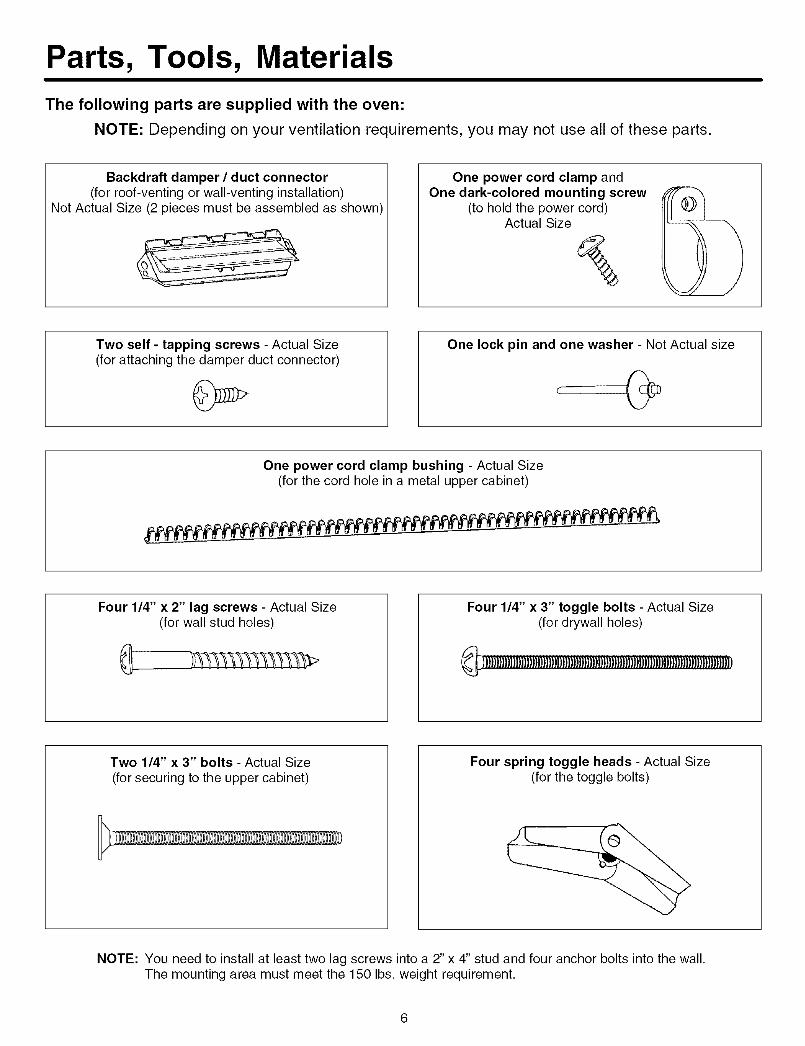
The following parts are supplied with the oven:
NOTE: Depending on your ventilation requirements, you may not use all of these parts.
Backdraft damper / duct connector(for roof-venting or wall-venting installation)
Not Actual Size (2 pieces must be assembled as shown)
One power cord clamp andOne dark-colored mounting screw
(to hold the power cord)Actual Size
Two self - tapping screws - Actual Size(for attaching the damper duct connector)
One lock pin and one washer - Not Actual size
One power cord clamp bushing - Actual Size(for the cord hole in a metal upper cabinet)
Four 1/4" x 2" lag screws - Actual Size(for wall stud holes)
Four 1/4" x 3" toggle bolts - Actual Size(for drywall holes)
_]_l)_)_}_)_))_]_)))_}_)))_))_)D_)_]_}_))_})_]_)_)_)_j))))_)
Two 1/4" x 3" bolts - Actual Size(for securing to the upper cabinet)
Four spring toggle heads - Actual Size(for the toggle bolts)
NOTE: You need to install at least two lag screws into a 2" x 4" stud and four anchor bolts into the wall.The mounting area must meet the 150 Ibs. weight requirement.
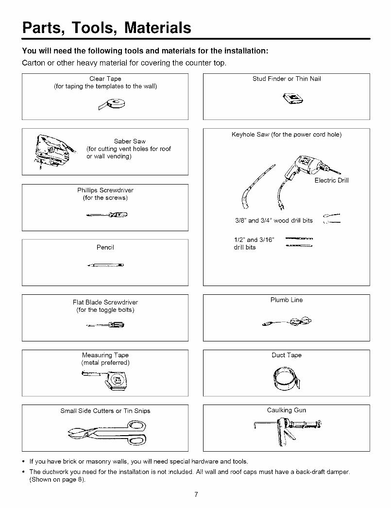
Parts, Tools, Materials
You will need the following tools and materials for the installation:
Carton or other heavy material for covering the counter top.
Clear Tape(for taping the templates to the wall)
Stud Finder or Thin Nail
Saber Saw(for cutting vent holes for roofor wall vending)
Phillips Screwdriver(for the screws)
Pencil
Keyhole Saw (for the power cord hole)
1/2" and 3/16"drill bits
Flat Blade Screwdriver(for the toggle bolts)
Plumb Line
Measuring Tape(metal preferred)
Duct Tape
Small Side Cutters or Tin Snips Caulking Gun
• If you have brick or masonry walls, you will need special hardware and tools.
• The ductwork you need for the installation is not included. All wall and roof caps must have a back-draft damper.(Shown on page 6).
STEP 1: Prepare The Electrical Connections
, WARNING,
AVOID ELECTRICAL SHOCK! THIS APPLIANCE MUST BE GROUNDED!
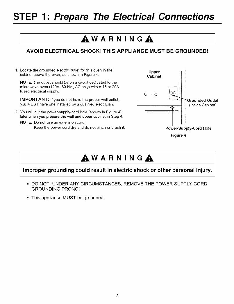
1. Locate the grounded electric outlet for this oven in thecabinet above the oven, as shown in Figure 4.
NOTE: The outlet should be on a circuit dedicated to themicrowave oven (120V, 60 Hz., AC only) with a 15 or 20Afused electrical supply.
IMPORTANT: If you do not have the proper wall outlet,you MUST have one installed by a qualified electrician.
2. You will cut the power-supply-cord hole (shown in Figure 4)later when you prepare the wall and upper cabinet in Step 4.
NOTE: Do not use an extension cord.
Keep the power cord dry and do not pinch or crush it.
UpperCabinet
! .....
IPower-Supply-Cord Hole
"" Grounded Outlet(Inside Cabinet)
Figure 4
, WARNING,
Improper grounding could result in electric shock or other personal injury.
• DO NOT, UNDER ANY CIRCUMSTANCES, REMOVE THE POWER SUPPLY CORDGROUNDING PRONG!
• This appliance MUST be groundedt
STEP 2: Prepare The Venting System
NOTE: The ductwork you need for outside ventilation is not included with your oven. The standard ductworkfittings and length are shown in Figure 9, page 10.
ILWARNING-FIRE HAZARD
THIS OVEN MUST BE PROPERLY VENTED!
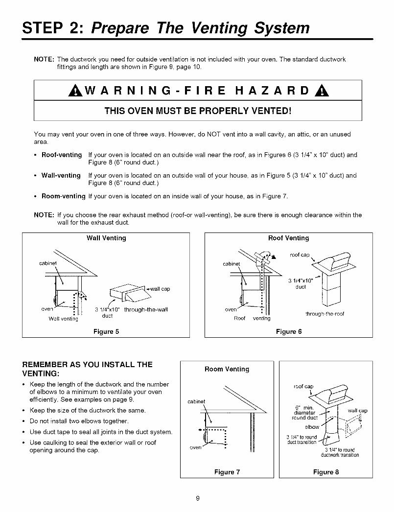
You may vent your oven in one of three ways. However, do NOT vent into a wall cavity, an attic, or an unusedarea.
• Roof-venting If your oven is located on an outside wall near the roof, as in Figures 6 (3 1/4" x 10" duct) andFigure 8 (6" round duct.)
• Wall-venting If your oven is located on an outside wall of your house, as in Figure 5 (3 1/4" x 10" duct) andFigure 8 (6" round duct.)
• Room-venting If your oven is located on an inside wall of your house, as in Figure 7.
NOTE: If you choose the rear exhaust method (roof-or wall-venting), be sure there is enough clearance within thewall for the exhaust duct.
Wall Venting
cabin____
oven__ 3 l_z__'_veillwC::
Wall venting
Figure 5
Roof Venting
o_h_net__=_ii ''_ roorc_p
"J\ lil 31/4"x10" I I I
oven_ duct _]
through-the-roofRoof venting
Figure 6
REMEMBER AS YOU INSTALL THEVENTING:
• Keep the length of the ductwork and the numberof elbows to a minimum to ventilate your ovenefficiently. See examples on page 9.
• Keep the size of the ductwork the same.
• Do not install two elbows together.
• Use duct tape to seal all joints in the duct system.
• Use caulking to seal the exterior wall or roofopening around the cap.
Room Venting
cabinet
Figure 7
roof ca p
__arain,d%mround duct -L_'t-. <::-_I_"
elbow'1 L ;,_:._3 114"tOround !!'_
duct transition
3 1t4" to roundducb,,_orktransition
Figure 8
STEP 2: Prepare The Venting System
Standard Fittings
NOTE: If the existing duct is round, you must use a rectangular-to-round adapter, with a rectangular 3" extensionduct installed between the damper assembly and the adapter to prevent the exhaust damper's sticking.
Duct Length
The total length of the duct system, including straight duct, elbows, transitions, and wall or roof caps must notexceed the equivalent of 140 feet.
For best performance, do not use more than three 90 degree elbows, and keep length as short as possible.
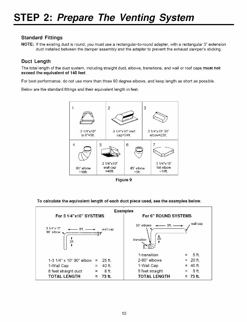
Below are the standard fittings and their equivalent length in feet.
3 1/4"x10"to 6"=5ft.
3 1/4"x10" roofcap=24ft.
3
3 1t4"x10" 90 °elbow=25tt.
90" elbow=10ft.
5
3 1/4"x10"
walt cap=40ft.
6
45" elbow:5ft.
7
3 1/4"x10"flat elbow
=10ft.
Figure 9
To calculate the equivalent length of each duct piece used, see the examples below.
For 3 1/4"x10" SYSTEMSExam
1-31/4" x10" 90° elbow = 25ft.
1-Wall Cap = 40 ft.8 feet straight duct = 8 ft.TOTAL LENGTH = 73 ft.
_lesFor 6" ROUND SYSTEMS
90" elbows _ 6ft. _ wall cap
1-transition = 5 ft.2-90 ° elbows = 20 ft.
1-Wall Cap = 40 ft.8 feet straight = 8 ft.TOTAL LENGTH = 73 ft.
10
STEP 3: Prepare The Venting Blower
To avoid risk of property damage, unplug the microwave oven or disconnect power atsource by removing fuse or throwing circuit breaker.
To avoid risk of personal injury, wear protective gloves when handling mounting plate.
Before You Start
1. Remove any shipping materials and parts from inside themicrowave oven.
2. Cover the counter top or cooktop with a thick, protectivecovering to protect it from damage and dirt. See Figure 10.
NOTE: If you have a free-standing range, disconnect it, move itonto a piece of cardboard or hardboard and pull it awayfrom the wall, so that you can get closer to the uppercabinet and back wall for easier measuring and drilling.
STEP 3: Prepare The Venting Blower
4. Reassemble the blower wire. See Figure 14.
5. Rotate the unit so that the exhaust ports face the rear of the cabinet. See Figure 15. When you insert blower unit,blower wire must be like figure 15.
6. Place blower unit back into cabinet. Check that the exhaust ports face towards the rear of the cabinet. See Figure 16.
7. Reattach the blower plate to cabinet so the exhaust ports and blower plate opening are aligned. Attach with one blowerunit mounting screw and then one or two blower plate screw(s). See Figure 17.
Figure 14 Figure 15
Root-Vented Installation:
1. Remove one blower unit mounting screw and one or twoblower plate screw(s). Remove the blower plate from cabinet.See Figure 18.
O II_ eirta ,-'l iffar r_r thin chine tr_ ,-'l it _nr,I rarnr_\/a n_rte "_"
STEP 4: Prepare The Wall & Upper Cabinet
, WARNING,
To avoid personal injury or property damage, do not attempt to install this microwaveoven if you cannot find a wall stud.
Measure And Track/Tape Up The Templates
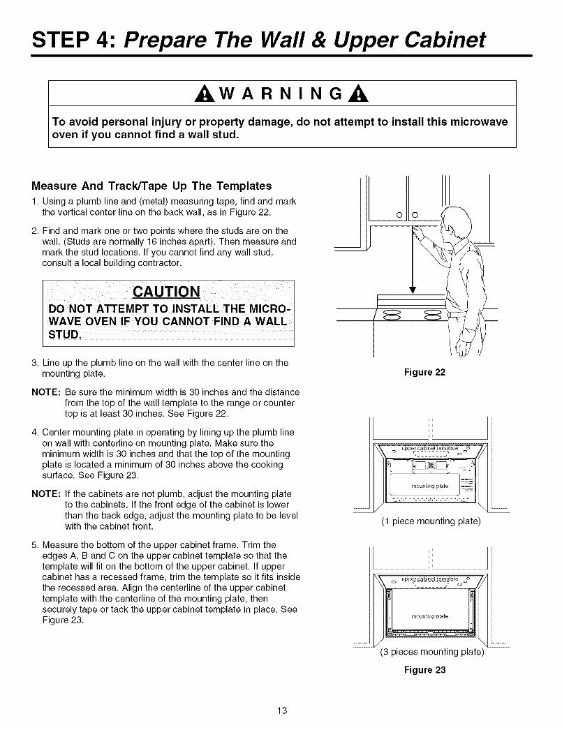
1. Using a plumb line and (metal) measuring tape, find and markthe vertical center line on the back wall, as in Figure 22.
2. Find and mark one or two points where the studs are on thewall. (Studs are normally 16 inches apart). Then measure andmark the stud locations. If you cannot find any wall stud,consult a local building contractor.
DO NOT ATTEMPT TO INSTALL THE MICRO,WAVE OVEN IF YOU CANNOT FINDA WALL
STUD,
3. Line up the plumb line on the wall with the center line on themounting plate.
NOTE: Be sure the minimum width is 30 inches and the distancefrom the top of the wall template to the range or countertop is at least 30 inches. See Figure 22.
4. Center mounting plate in operating by lining up the plumb lineon wall with centerline on mounting plate. Make sure theminimum width is 30 inches and that the top of the mountingplate is located a minimum of 30 inches above the cookingsurface. See Figure 23.
NOTE: If the cabinets are not plumb, adjust the mounting plateto the cabinets. If the front edge of the cabinet is lowerthan the back edge, adjust the mounting plate to be levelwith the cabinet front.
5. Measure the bottom of the upper cabinet frame. Trim theedges A, B and C on the upper cabinet template so that thetemplate will fit on the bottom of the upper cabinet. If uppercabinet has a recessed frame, trim the template so it fits insidethe recessed area. Align the centerline of the upper cabinettemplate with the centerline of the mounting plate, thensecurely tape or tack the upper cabinet template in place. SeeFigure 23.
Figure 22
(1 piece mounting plate)
(3 pieces mounting plate)
Figure 23
13
STEP 4: Prepare The Wall & Upper Cabinet
, WARNING,
To avoid risk of personal injury, electrical shock or death:
° Note where electrical outlets and electrical wires are before you drill into the wall.
° Locate and disconnect power to any electrical circuits that could be affected byinstalling this oven.
, WARNING,
To avoid risk of personal injury, electrical shock or death, cover the edge of the powersupply cord hole with the power supply cord bushing.
Drill The Holes In The Wall And Upper Cabinet.
1. Find the points on the mounting plate labeled A, B, C, and D.Drill a 3/16" diameter hole at any points that are over a wallstud. Drill a 3/4" diameter hole at any points over drywall.
2. Drill a 3/8" hole at points J, K, and N on the upper cabinettemplate.
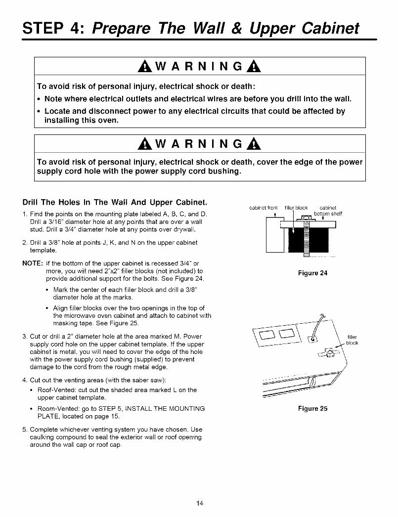
NOTE: If the bottom of the upper cabinet is recessed 3/4" ormore, you will need 2"x2" filler blocks (not included) toprovide additional support for the bolts. See Figure 24.
• Mark the center of each filler block and drill a 3/8"diameter hole at the marks.
• Align filler blocks over the two openings in the top ofthe microwave oven cabinet and attach to cabinet withmasking tape. See Figure 25.
3. Cut or drill a 2" diameter hole at the area marked M. Powersupply cord hole on the upper cabinet template. If the uppercabinet is metal, you will need to cover the edge of the holewith the power supply cord bushing (supplied) to preventdamage to the cord from the rough metal edge.
4. Cut out the venting areas (with the saber saw):
• Roof-Vented: cut out the shaded area marked L on theupper cabinet template.
• Room-Vented: go to STEP 5, INSTALL THE MOUNTINGPLATE, located on page 15.
5. Complete whichever venting system you have chosen. Usecaulking compound to seal the exterior wall or roof openingaround the wall cap or roof cap.
cabinet front filler block cabinetbottom shelf
Figure 24
Figure 25
14
STEP 5: Install The Mounting Plate
The Oven Must Be Connected To At Least OneWall Stud.
1. Draw a vertical line on the wall at the center of the 30 widespace. Use the mounting plate as the template for the rearwall. Place the mounting plate on the wall, making sure thatthe tabs are against the bottom of the cabinet. L
STEP 5: Install The Mounting Plate
For Wall-Vented
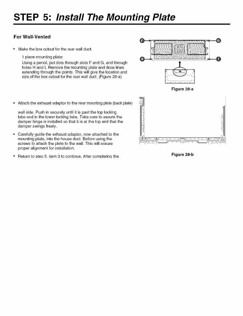
Make the box cutout for the rear wall duct.
1 piece mounting plate:
Using a pencil, put dots through slots F and G, and throughholes H and I. Remove the mounting plate and draw linesextending through the points. This will give the location andsize of the box cutout for the rear wall duct. (Figure 28-a)
.4-.
Figure 28-a
Attach the exhaust adaptor to the rear mounting plate (back plate)
wall side. Push in securely until it is past the top lockingtabs and in the lower locking tabs. Take care to assure thedamper hinge is installed so that it is at the top and that thedamper swings freely.
Carefully guide the exhaust adaptor, now attached to themounting plate, into the house duct. Before using thescrews to attach the plate to the wall. This will assureproper alignment for installation.
Return to step 5. item 3 to continue. After comDletina the Figure 28-b
STEP 6: Attach The Oven To The Wall
WARNING
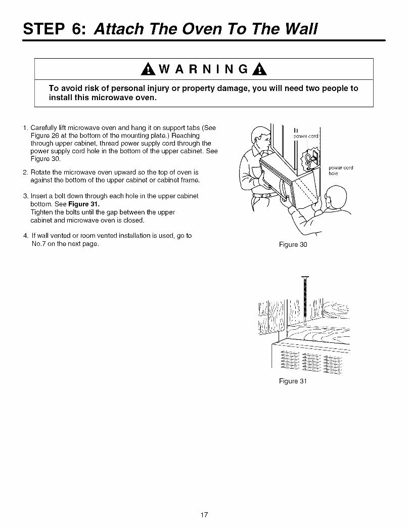
To avoid risk of personal injury or property damage, you will need two people toinstall this microwave oven.
1. Carefully lift microwave oven and hang it on support tabs (SeeFigure 26 at the bottom of the mounting plate.) Reachingthrough upper cabinet, thread power supply cord through thepower supply cord hole in the bottom of the upper cabinet. SeeFigure 30.
2. Rotate the microwave oven upward so the top of oven isagainst the bottom of the upper cabinet or cabinet frame.
3. Insert a bolt down through each hole in the upper cabinetbottom. See Figure 31.Tighten the bolts until the gap between the uppercabinet and microwave oven is closed.
4. If wall vented or room vented installation is used, go toNo.7 on the next page.
o
power cord
Figure 30
Figure 31
17
STEP 6: Attach The Oven To The Wall
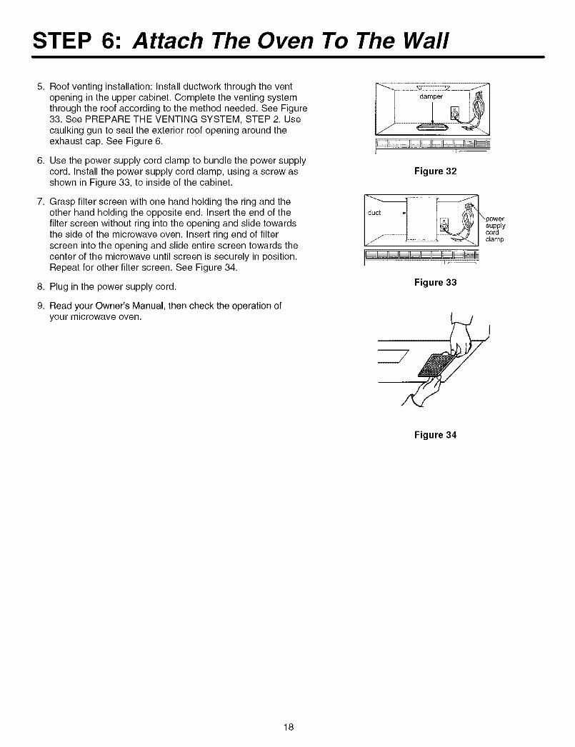
5. Roof venting installation: Install ductwork through the ventopening in the upper cabinet. Complete the venting systemthrough the roof according to the method needed. See Figure33. See PREPARE THE VENTING SYSTEM, STEP 2. Usecaulking gun to seal the exterior roof opening around theexhaust cap. See Figure 6.
6. Use the power supply cord clamp to bundle the power supplycord. Install the power supply cord clamp, using a screw asshown in Figure 33, to inside of the cabinet.
7. Grasp filter screen with one hand holding the ring and theother hand holding the opposite end. Insert the end of thefilter screen without ring into the opening and slide towardsthe side of the microwave oven. Insert ring end of filterscreen into the opening and slide entire screen towards thecenter of the microwave until screen is securely in position.Repeat for other filter screen. See Figure 34.
8. Plug in the power supply cord.
9. Read your Owner's Manual, then check the operation ofyour microwave oven.
Figure 32
power
supplycord
clamp
II _----
Figure 33
Figure 34
18

A-08-02PrintedinChina03-04
©2004 Maytag Appliance Sales Co. Part No. 8101 P632-603828W5U0337
(08-02-01)


![ELECTRICRANGE - partselectcom.azureedge.net · other servicing should be referred to a qualified technician. [] ... burner will also improve efficiency. [] ... Right front control](https://img.pdfslide.us/doc/110x75/5af93d137f8b9a19548c5ba8/electricrange-servicing-should-be-referred-to-a-qualified-technician-burner.jpg)