Embed Size (px)
Citation preview
INSTALLATION INSTRUCTIONS MODEL NUMBER PVH58
HORIZONTAL POWER VENT TERMINATION
Certified To: ANSI Z21.50-2014 • CSA 2.22-2014
ZERO CLEARANCE VENTED GAS FIREPLACE Certified to: ANSI Z21.88-2014 • CSA 2.33-2014
ZERO CLEARANCE VENTED GAS FIREPLACE HEATER
Printed in Canada April 9, 2018 Part # 58PVH-MAN
INSTALLATION TO BE DONE BY A QUALIFIED INSTALLER. This appliance, when installed, must be electrically connected and grounded in accordance with local codes, or in the absence of local codes, with the current CSA C22.1 Canadian Electrical Code or with the national Electrical Code; ANSI/NFPA 70-1987 when installed in the United States. The PVH-58 Horizontal Power Vent Termination operates on 120 VAC Power, which is supplied by the junction box inside the fireplace.
NOTE: MODELS EQUIPPPED WITH INTERMITTENT PILOT IGNITION (PROFLAME 1 or PROFLAME 2): Downward vertical vent runs are permitted, however, Cold Climate Switch (Standing Pilot Mode) must NOT be used.
NOTE: MODELS EQUIPPPED WITH MILLIVOLT/ STANDING PILOT IGNITION: Downward vertical vent runs are NOT permitted.
The PVH58 Horizontal Power Vent Termination is intended for use where standard venting configurations are not possible.
READ THIS COMPLETE MANUAL BEFORE BEGINNING INSTALLATION. THESE INSTRUCTIONS MUST BE KEPT ALONG WITH THE APPLIANCE INSTRUCTIONS FOR FUTURE REFERENCE.
INSTALLER: LEAVE THIS MANUAL WITH THE APPLIANCE. CONSUMER: RETAIN THIS MANUAL FOR FUTURE REFERENCE.
Kingsman Fireplaces A Division of R-Co. Inc. 2340 Logan Avenue Winnipeg, Manitoba, Canada R2R 2V3 Ph: (204) 632-1962
⚠ WARNING: Improper installation, adjustment, alteration, service or maintenance can cause injury or property damage. Refer to the owner’s information manual provided with this appliance. For assistance or additional information consult a qualified installer, service agency, or the gas supplier.
⚠ WARNING: If the information in these instructions is not followed exactly, a fire or explosion may result causing property damage, personal injury or loss of life.
BENTLEY
PVH58 Table of Contents
Table Of Contents.......................................................................................... 2
Warnings, Installations And Operations......................................................... 3
Installation Requirements For The Commonwealth Of Massachusetts......... 4
58PVH Dimensions........................................................................................ 5
Installation Overview...................................................................................... 6
Termination Installation.................................................................................. 6
Venting Clearances........................................................................................ 7
PVH58 Venting - Hard Pipe Or Flex............................................................... 8-9
Venting Configurations................................................................................... 10
Wall Thimble Installation................................................................................ 11
Power Vent Mounting..................................................................................... 11
PVH20H – Main Wiring Harness Extension……………………………………. 12
58PVH-P124 Double Pole Switch –Millivolt Systems Only…………………... 12
Bentley ZCV39 / ZCV42 Power Vent Control Module Installation…………… 13
Bentley ST MCVST42 Power Vent Control Module Installation……………... 14
Atrium MCVP42 Power Vent Control Module Installation…………………….. 15
Infinite Series 4436 / 5143 / 6961 Power Vent Control Module Installation… 16
Kingsman ZRB46 Power Vent Control Module Installation…………………... 17
Millivolt System Connections.......................................................................... 18
PVCM Schematic – Millivolt........................................................................... 19
IPI System Connections................................................................................. 20
Basic IPI System Connections....................................................................... 21
Remote Receiver Without Batteries For EGT / EGTM Remote Controls....... 22
All IPI System Connections............................................................................ 23
PVCM Schematic – IPI.................................................................................. 24-25
IPI System 2 Connections.............................................................................. 26-27
Air Intake Adjustment..................................................................................... 28
Troubleshooting.............................................................................................. 29
Parts List........................................................................................................ 30-31
Limited Lifetime Warranty.............................................................................. 32
2
Warnings, Installations and Operations
Installation Regulations This gas appliance must be installed by a qualified installer in accordance with local building codes, or in the absence of local codes, with the current CAN/CSA-B149.1 or .2 Installation Code (in Canada) or the current National Fuel Gas Code Z223.1- NFPA 54 when installed in the United States. This appliance, when installed, must be electrically connected and grounded in accordance with local codes, or in the absence of local codes, with the current CSA C22.1 Canadian Electrical Code or with the National Electrical Code; ANSI/NFPA 70 when installed in the United States. In the U.S.A. Thermostats are not permitted for Vented Gas Fireplaces (ANSI Z21.50b-Decorative).
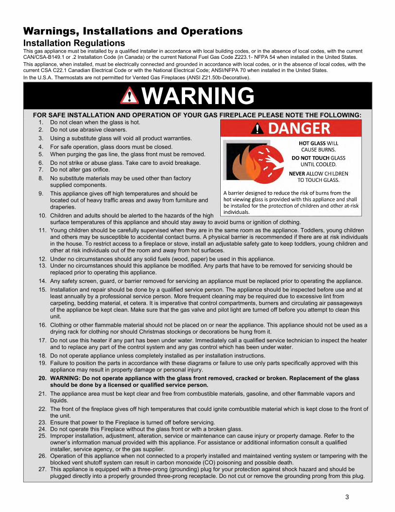
WARNING
FOR SAFE INSTALLATION AND OPERATION OF YOUR GAS FIREPLACE PLEASE NOTE THE FOLLOWING: 1. Do not clean when the glass is hot. 2. Do not use abrasive cleaners. 3. Using a substitute glass will void all product warranties. 4. For safe operation, glass doors must be closed. 5. When purging the gas line, the glass front must be removed. 6. Do not strike or abuse glass. Take care to avoid breakage. 7. Do not alter gas orifice. 8. No substitute materials may be used other than factory
supplied components. 9. This appliance gives off high temperatures and should be
located out of heavy traffic areas and away from furniture and draperies.
10. Children and adults should be alerted to the hazards of the high surface temperatures of this appliance and should stay away to avoid burns or ignition of clothing.
11. Young children should be carefully supervised when they are in the same room as the appliance. Toddlers, young children and others may be susceptible to accidental contact burns. A physical barrier is recommended if there are at risk individuals in the house. To restrict access to a fireplace or stove, install an adjustable safety gate to keep toddlers, young children and other at risk individuals out of the room and away from hot surfaces.
12. Under no circumstances should any solid fuels (wood, paper) be used in this appliance. 13. Under no circumstances should this appliance be modified. Any parts that have to be removed for servicing should be
replaced prior to operating this appliance. 14. Any safety screen, guard, or barrier removed for servicing an appliance must be replaced prior to operating the appliance. 15. Installation and repair should be done by a qualified service person. The appliance should be inspected before use and at
least annually by a professional service person. More frequent cleaning may be required due to excessive lint from carpeting, bedding material, et cetera. It is imperative that control compartments, burners and circulating air passageways of the appliance be kept clean. Make sure that the gas valve and pilot light are turned off before you attempt to clean this unit.
16. Clothing or other flammable material should not be placed on or near the appliance. This appliance should not be used as a drying rack for clothing nor should Christmas stockings or decorations be hung from it.
17. Do not use this heater if any part has been under water. Immediately call a qualified service technician to inspect the heater and to replace any part of the control system and any gas control which has been under water.
18. Do not operate appliance unless completely installed as per installation instructions. 19. Failure to position the parts in accordance with these diagrams or failure to use only parts specifically approved with this
appliance may result in property damage or personal injury. 20. WARNING: Do not operate appliance with the glass front removed, cracked or broken. Replacement of the glass
should be done by a licensed or qualified service person. 21. The appliance area must be kept clear and free from combustible materials, gasoline, and other flammable vapors and
liquids. 22. The front of the fireplace gives off high temperatures that could ignite combustible material which is kept close to the front of
the unit. 23. Ensure that power to the Fireplace is turned off before servicing. 24. Do not operate this Fireplace without the glass front or with a broken glass. 25. Improper installation, adjustment, alteration, service or maintenance can cause injury or property damage. Refer to the
owner’s information manual provided with this appliance. For assistance or additional information consult a qualified installer, service agency, or the gas supplier.
26. Operation of this appliance when not connected to a properly installed and maintained venting system or tampering with the blocked vent shutoff system can result in carbon monoxide (CO) poisoning and possible death.
27. This appliance is equipped with a three-prong (grounding) plug for your protection against shock hazard and should be plugged directly into a properly grounded three-prong receptacle. Do not cut or remove the grounding prong from this plug.
3
Gas fired appliances may be used only for supplemental heat and/or decorative purposes and under no circumstances shall they provide a primary heat source.
This appliance must not be connected to a chimney flue serving a separate solid-fuel burning appliance.
NOTE: It is recommended that a Carbon Monoxide (CO) Detector be installed in or near bedrooms and on all levels of your home. Place a detector about 15ft [4.5m] outside the room that houses your gas appliance.
Certified for installation in a bedroom or bed/sitting room. In Canada must be installed with listed millivolt thermostat. In the U.S.A. Thermostats are not permitted for Vented Gas Fireplaces (ANSI Z21.50b-Decorative).
In USA see local codes.
Operations and Maintenance Instructions
For safe installation and operation note the following: • Venting systems should be periodically examined by a qualified agency. • The flow of combustion and ventilation air must not be obstructed. • The Burner/Log Assembly has been engineered and permanently adjusted for proper flame control. • Periodically remove the logs from the grate assembly and vacuum any loose particles from the grate and burner areas. See Log
Placement page to remove logs. Vacuum burner parts and replace logs. • Never use your gas fireplace as a cooking device. • Label all wires prior to disconnection when servicing controls. Wiring errors can cause improper and dangerous operation. Verify
proper operation after servicing.
Installation Requirements for the Commonwealth of
Massachusetts
In the Commonwealth of Massachusetts, the installer or service agent shall be a plumber or gas fitter licensed by the Commonwealth. When installed in the Commonwealth of Massachusetts or where applicable codes; the unit shall be installed with a CO detector per the requirements listed below. 1. For direct-vent appliances, mechanical-vent heating appliances or domestic hot water equipment, where the bottom of the vent
terminal and the air intake is installed below four feet above grade the following requirements must be satisfied: A. If there is not one already present, on each floor level where there are bedroom(s), a carbon monoxide detector and alarm
shall be placed in the living area outside the bedroom(s). The carbon monoxide detector shall comply with NFPA 720. B. A carbon monoxide detector shall be located in the room that houses the appliance or equipment and shall:
Be powered by the same electrical circuit as the appliance or equipment such that only one service switch services both the appliance and the carbon monoxide detector;
Have battery back-up power;
Meet ANSI./UL 2034 Standards and comply with NFPA 720; and
Have been approved and listed by a Nationally Recognized Testing Laboratory as recognized under 527 CMR.
C. A Product-approved vent terminal must be used, and if applicable, a Product-approved air intake must be used. Installation shall be in strict compliance with the manufacturer’s instructions. A copy of the installation instructions shall remain with the appliance or equipment at the completion of the installation.
D. A metal or plastic identification plate shall be mounted at the exterior of the building, four feet directly above the location of vent terminal. The plate shall be of sufficient size to be easily read from a distance of eight feet away, and read “Gas Vent Directly Below”.
2. For direct-vent appliances, mechanical-vent heating appliances or domestic hot water equipment where the bottom of the vent terminal and the air intake is installed above four feet above grade the following requirements must be satisfied:
A. If there is not one already present, on each floor level where there are bedroom(s), a carbon monoxide detector and alarm shall be placed in the living area outside the bedroom(s). The carbon monoxide detector shall comply with NFPA 720.
B. A carbon monoxide detector shall: Be located in the room that houses the appliance or equipment; Be either hard-wired or battery powered or both; and Shall comply with NFPA 720.
A Product-approved vent terminal must be used, and if applicable, a Product-approved air intake must be used. Installation shall be in strict compliance with the manufacturer instructions. A copy of the installation instructions shall remain with the appliance or equipment at the completion of the installation.
For the state of Massachusetts a T-handle gas shut-off valve must be used on a gas appliance. This T-handle gas shut-off valve must be listed and approved by the state of Massachusetts. This is in reference to the state of Massachusetts state code CMR238.
4
5"
1-1/2"
1/2"
10-5/8"
1-1/4"
8-1/8"
12-1/2"
16"
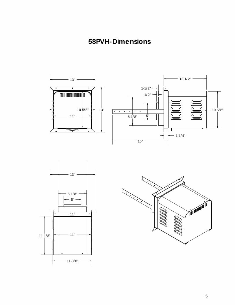
58PVH-Dimensions
13"
13"10-5/8"
11"
13"
11"
11"
11-3/8"
5"8-1/8"
11-1/8"
5
PVH58 Installation Overview Either Hard Pipe or Flex Pipe can be used, along with the appropriate adapter kit.
The Following Steps Are Required To Install The PVH58 Horizontal Power Vent: Install fireplace as per manual instructions.
Choose suitable location for PVH58 Power Vent Termination. Refer to Termination Installation and PVH58 Venting Clearances sections of this manual.
Determine venting configuration to be used (i.e. hard pipe or flex, and routing). Install venting with appropriate adapter kits. See PVH58 Venting – Hard Pipe or Flex, and PVH58 Venting Configurations sections of this manual.
Install PVH58 Wall Thimble if mounting in a combustible wall. Refer to PVH58 Wall Thimble Installation section.
Install PVH58 Power Vent (refer to PVH58 Power Vent Mounting section) and venting.
Install Power Vent Control Module in fireplace. Refer to Power Vent Control Module Installation.
Electrical connections (PVH58 Wiring Harness Connections and Millivolt / IPI System Connections sections).
Air Intake Adjustment & Troubleshooting (refer to these sections).
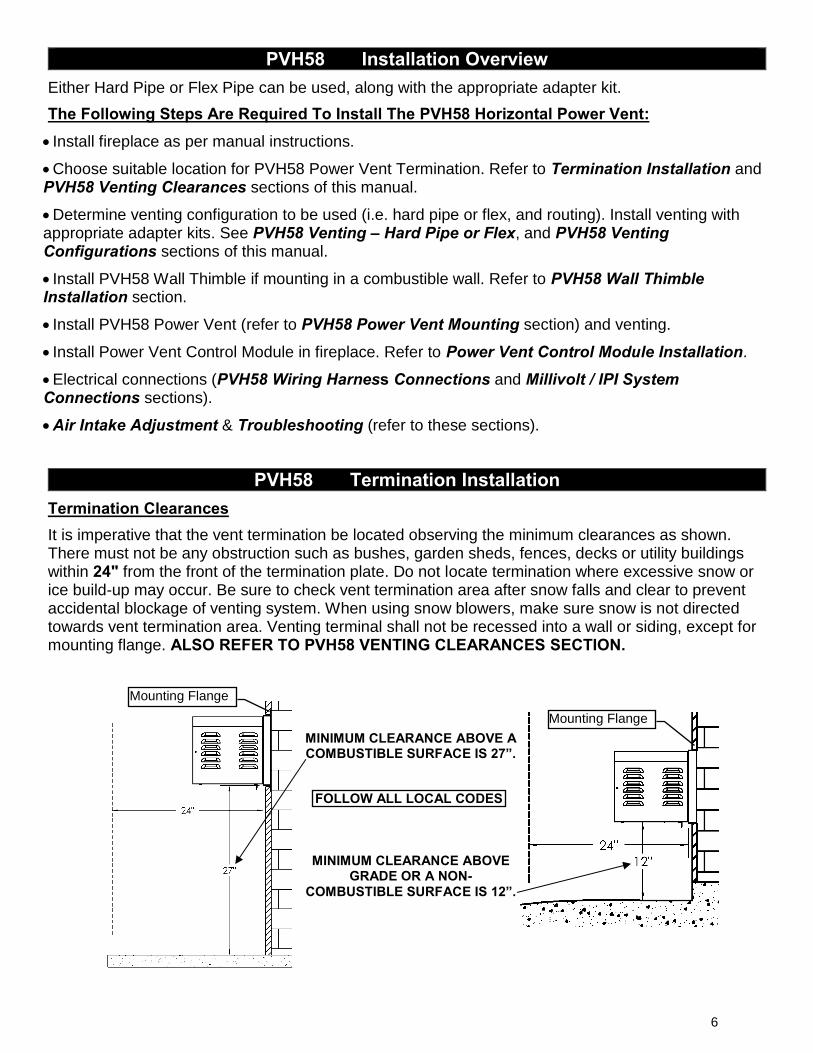
PVH58 Termination Installation Termination Clearances It is imperative that the vent termination be located observing the minimum clearances as shown. There must not be any obstruction such as bushes, garden sheds, fences, decks or utility buildings within 24" from the front of the termination plate. Do not locate termination where excessive snow or ice build-up may occur. Be sure to check vent termination area after snow falls and clear to prevent accidental blockage of venting system. When using snow blowers, make sure snow is not directed towards vent termination area. Venting terminal shall not be recessed into a wall or siding, except for mounting flange. ALSO REFER TO PVH58 VENTING CLEARANCES SECTION.
MINIMUM CLEARANCE ABOVE A COMBUSTIBLE SURFACE IS 27”.
MINIMUM CLEARANCE ABOVE GRADE OR A NON-
COMBUSTIBLE SURFACE IS 12”.
FOLLOW ALL LOCAL CODES
Mounting Flange
Mounting Flange
6
PVH58 VENTING CLEARANCES
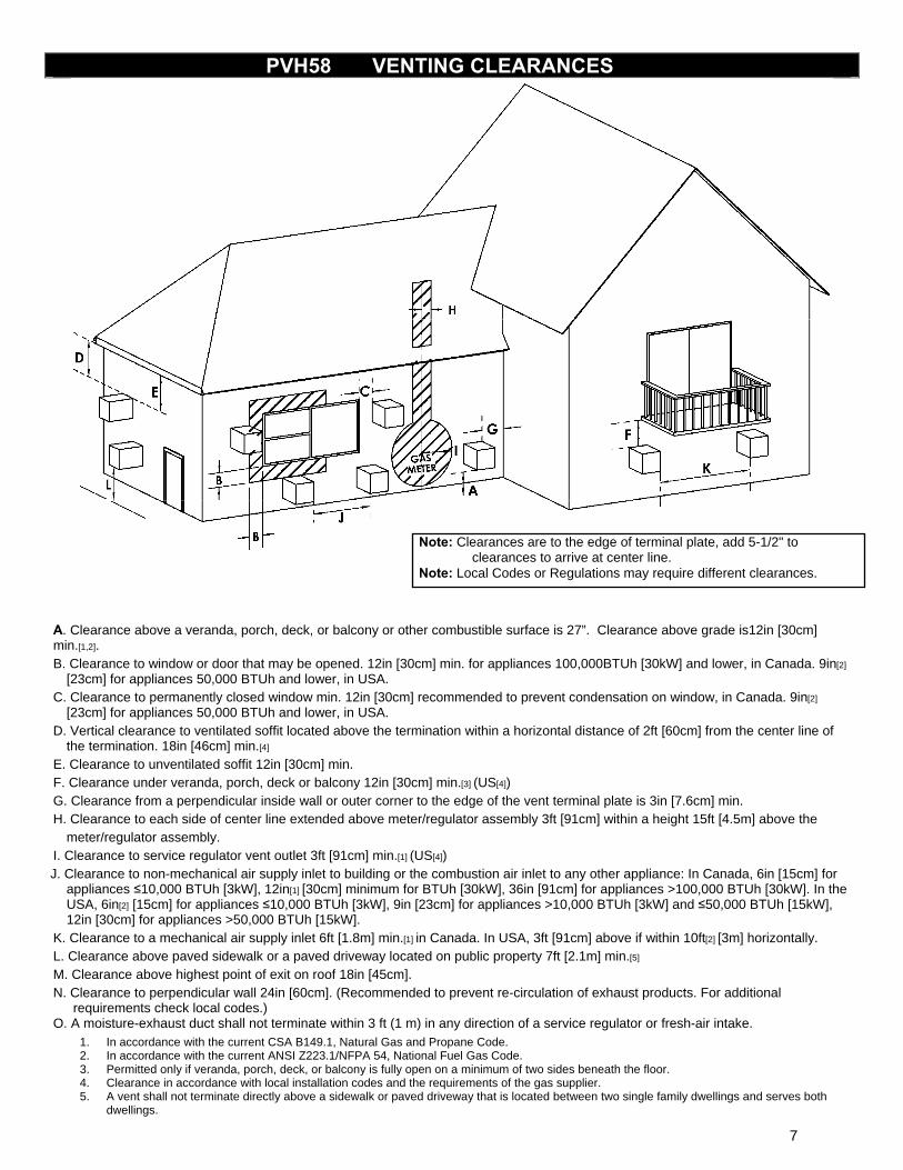
Note: Clearances are to the edge of terminal plate, add 5-1/2" to clearances to arrive at center line. Note: Local Codes or Regulations may require different clearances.
A. Clearance above a veranda, porch, deck, or balcony or other combustible surface is 27”. Clearance above grade is12in [30cm] min.[1,2]. B. Clearance to window or door that may be opened. 12in [30cm] min. for appliances 100,000BTUh [30kW] and lower, in Canada. 9in[2]
[23cm] for appliances 50,000 BTUh and lower, in USA. C. Clearance to permanently closed window min. 12in [30cm] recommended to prevent condensation on window, in Canada. 9in[2]
[23cm] for appliances 50,000 BTUh and lower, in USA. D. Vertical clearance to ventilated soffit located above the termination within a horizontal distance of 2ft [60cm] from the center line of
the termination. 18in [46cm] min.[4] E. Clearance to unventilated soffit 12in [30cm] min. F. Clearance under veranda, porch, deck or balcony 12in [30cm] min.[3] (US[4]) G. Clearance from a perpendicular inside wall or outer corner to the edge of the vent terminal plate is 3in [7.6cm] min. H. Clearance to each side of center line extended above meter/regulator assembly 3ft [91cm] within a height 15ft [4.5m] above the
meter/regulator assembly. I. Clearance to service regulator vent outlet 3ft [91cm] min.[1] (US[4])
J. Clearance to non-mechanical air supply inlet to building or the combustion air inlet to any other appliance: In Canada, 6in [15cm] for appliances ≤10,000 BTUh [3kW], 12in[1] [30cm] minimum for BTUh [30kW], 36in [91cm] for appliances >100,000 BTUh [30kW]. In the USA, 6in[2] [15cm] for appliances ≤10,000 BTUh [3kW], 9in [23cm] for appliances >10,000 BTUh [3kW] and ≤50,000 BTUh [15kW], 12in [30cm] for appliances >50,000 BTUh [15kW].
K. Clearance to a mechanical air supply inlet 6ft [1.8m] min.[1] in Canada. In USA, 3ft [91cm] above if within 10ft[2] [3m] horizontally. L. Clearance above paved sidewalk or a paved driveway located on public property 7ft [2.1m] min.[5] M. Clearance above highest point of exit on roof 18in [45cm]. N. Clearance to perpendicular wall 24in [60cm]. (Recommended to prevent re-circulation of exhaust products. For additional
requirements check local codes.) O. A moisture-exhaust duct shall not terminate within 3 ft (1 m) in any direction of a service regulator or fresh-air intake.
1. In accordance with the current CSA B149.1, Natural Gas and Propane Code. 2. In accordance with the current ANSI Z223.1/NFPA 54, National Fuel Gas Code. 3. Permitted only if veranda, porch, deck, or balcony is fully open on a minimum of two sides beneath the floor. 4. Clearance in accordance with local installation codes and the requirements of the gas supplier. 5. A vent shall not terminate directly above a sidewalk or paved driveway that is located between two single family dwellings and serves both
dwellings.
7
PVH58 VENTING HARD PIPE OR FLEX
Approved For 4/6-5/8”, 5/8” Hard Pipe
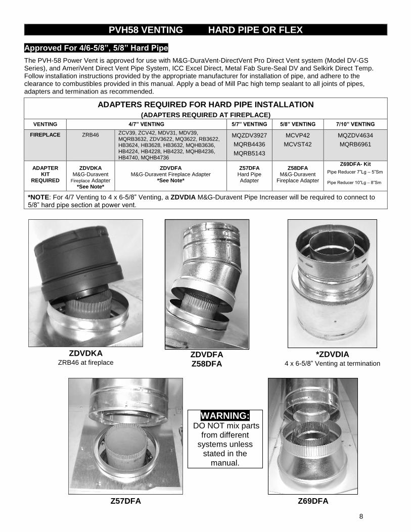
The PVH-58 Power Vent is approved for use with M&G-DuraVent-DirectVent Pro Direct Vent system (Model DV-GS Series), and AmeriVent Direct Vent Pipe System, ICC Excel Direct, Metal Fab Sure-Seal DV and Selkirk Direct Temp. Follow installation instructions provided by the appropriate manufacturer for installation of pipe, and adhere to the clearance to combustibles provided in this manual. Apply a bead of Mill Pac high temp sealant to all joints of pipes, adapters and termination as recommended.
ADAPTERS REQUIRED FOR HARD PIPE INSTALLATION
(ADAPTERS REQUIRED AT FIREPLACE) VENTING 4/7” VENTING 5/7” VENTING 5/8” VENTING 7/10” VENTING
FIREPLACE ZRB46
ZCV39, ZCV42, MDV31, MDV39, MQRB3632, ZDV3622, MQ3622, RB3622, HB3624, HB3628, HB3632, MQHB3636, HB4224, HB4228, HB4232, MQHB4236, HB4740, MQHB4736
MQZDV3927 MQRB4436 MQRB5143
MCVP42 MCVST42
MQZDV4634 MQRB6961
ADAPTER KIT
REQUIRED
ZDVDKA M&G-Duravent
Fireplace Adapter *See Note*
ZDVDFA M&G-Duravent Fireplace Adapter
*See Note*
Z57DFA Hard Pipe Adapter
Z58DFA M&G-Duravent
Fireplace Adapter
Z69DFA- Kit
Pipe Reducer 7”Lg – 5”Sm Pipe Reducer 10”Lg – 8”Sm
*NOTE: For 4/7 Venting to 4 x 6-5/8” Venting, a ZDVDIA M&G-Duravent Pipe Increaser will be required to connect to 5/8” hard pipe section at power vent.
ZDVDKA
ZRB46 at fireplace
ZDVDFA
Z58DFA
*ZDVDIA
4 x 6-5/8” Venting at termination
Z57DFA
Z69DFA
WARNING: DO NOT mix parts
from different systems unless
stated in the manual.
8
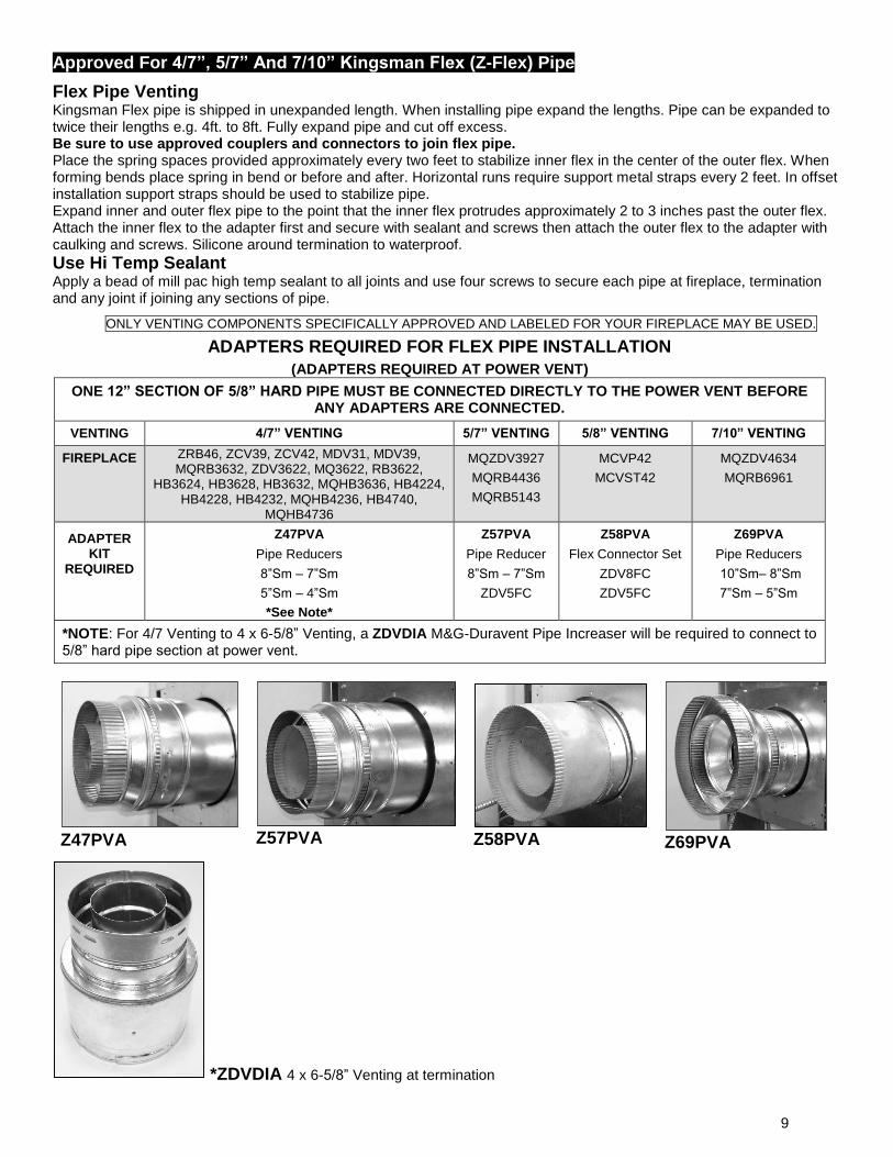
Approved For 4/7”, 5/7” And 7/10” Kingsman Flex (Z-Flex) Pipe
Flex Pipe Venting Kingsman Flex pipe is shipped in unexpanded length. When installing pipe expand the lengths. Pipe can be expanded to twice their lengths e.g. 4ft. to 8ft. Fully expand pipe and cut off excess. Be sure to use approved couplers and connectors to join flex pipe. Place the spring spaces provided approximately every two feet to stabilize inner flex in the center of the outer flex. When forming bends place spring in bend or before and after. Horizontal runs require support metal straps every 2 feet. In offset installation support straps should be used to stabilize pipe. Expand inner and outer flex pipe to the point that the inner flex protrudes approximately 2 to 3 inches past the outer flex. Attach the inner flex to the adapter first and secure with sealant and screws then attach the outer flex to the adapter with caulking and screws. Silicone around termination to waterproof. Use Hi Temp Sealant Apply a bead of mill pac high temp sealant to all joints and use four screws to secure each pipe at fireplace, termination and any joint if joining any sections of pipe.
ONLY VENTING COMPONENTS SPECIFICALLY APPROVED AND LABELED FOR YOUR FIREPLACE MAY BE USED.
ADAPTERS REQUIRED FOR FLEX PIPE INSTALLATION
(ADAPTERS REQUIRED AT POWER VENT)
ONE 12” SECTION OF 5/8” HARD PIPE MUST BE CONNECTED DIRECTLY TO THE POWER VENT BEFORE ANY ADAPTERS ARE CONNECTED.
VENTING 4/7” VENTING 5/7” VENTING 5/8” VENTING 7/10” VENTING
FIREPLACE ZRB46, ZCV39, ZCV42, MDV31, MDV39, MQRB3632, ZDV3622, MQ3622, RB3622,
HB3624, HB3628, HB3632, MQHB3636, HB4224, HB4228, HB4232, MQHB4236, HB4740,
MQHB4736
MQZDV3927 MQRB4436 MQRB5143
MCVP42 MCVST42
MQZDV4634 MQRB6961
ADAPTER KIT
REQUIRED
Z47PVA Pipe Reducers 8”Sm – 7”Sm 5”Sm – 4”Sm *See Note*
Z57PVA Pipe Reducer 8”Sm – 7”Sm
ZDV5FC
Z58PVA
Flex Connector Set ZDV8FC ZDV5FC
Z69PVA Pipe Reducers 10”Sm– 8”Sm 7”Sm – 5”Sm
*NOTE: For 4/7 Venting to 4 x 6-5/8” Venting, a ZDVDIA M&G-Duravent Pipe Increaser will be required to connect to 5/8” hard pipe section at power vent.
Z47PVA
Z57PVA
Z58PVA
Z69PVA
*ZDVDIA 4 x 6-5/8” Venting at termination
9
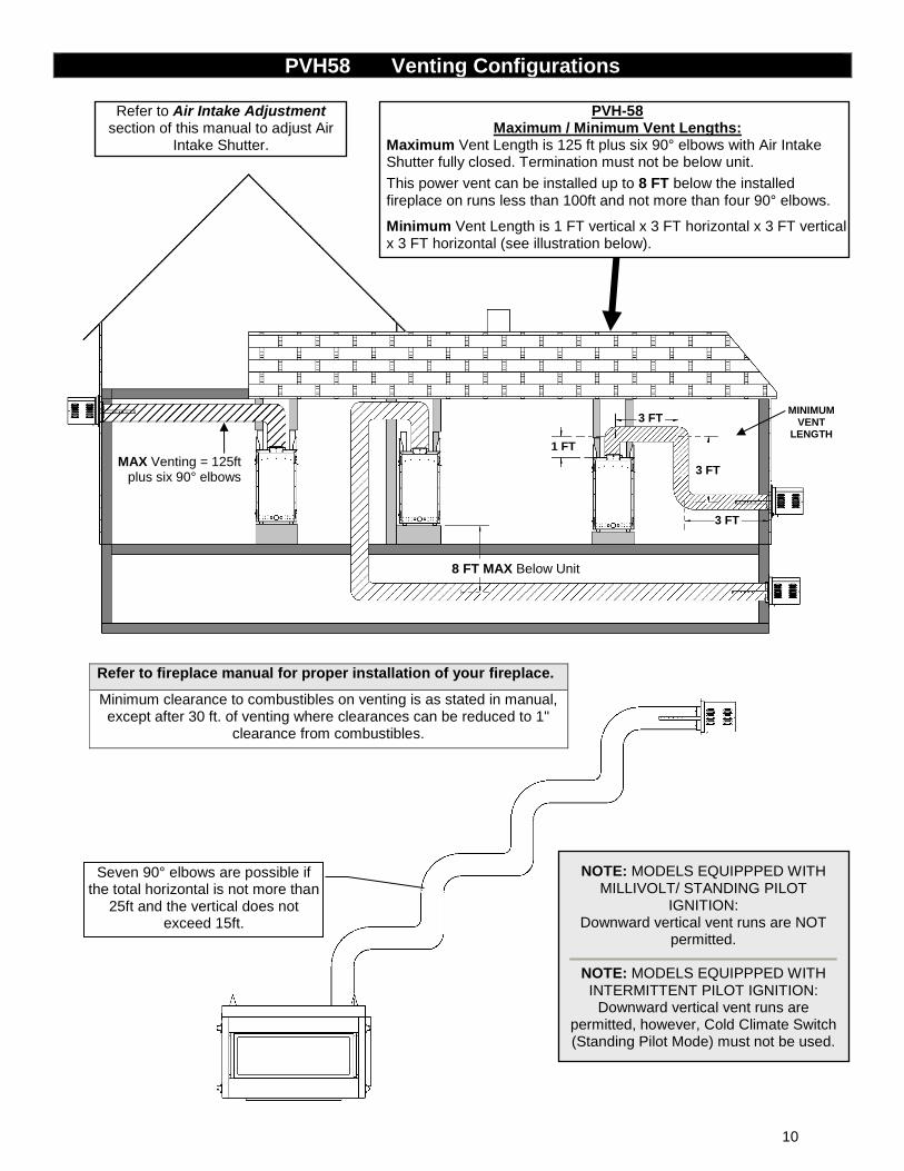
PVH58 Venting Configurations
8 FT MAX Below Unit
MAX Venting = 125ft plus six 90° elbows
PVH-58 Maximum / Minimum Vent Lengths:
Maximum Vent Length is 125 ft plus six 90° elbows with Air Intake Shutter fully closed. Termination must not be below unit.
This power vent can be installed up to 8 FT below the installed fireplace on runs less than 100ft and not more than four 90° elbows.
Minimum Vent Length is 1 FT vertical x 3 FT horizontal x 3 FT vertical x 3 FT horizontal (see illustration below).
Seven 90° elbows are possible if the total horizontal is not more than
25ft and the vertical does not exceed 15ft.
Refer to Air Intake Adjustment section of this manual to adjust Air
Intake Shutter.
NOTE: MODELS EQUIPPPED WITH MILLIVOLT/ STANDING PILOT
IGNITION: Downward vertical vent runs are NOT
permitted.
NOTE: MODELS EQUIPPPED WITH INTERMITTENT PILOT IGNITION:
Downward vertical vent runs are permitted, however, Cold Climate Switch (Standing Pilot Mode) must not be used.
Refer to fireplace manual for proper installation of your fireplace.
Minimum clearance to combustibles on venting is as stated in manual, except after 30 ft. of venting where clearances can be reduced to 1"
clearance from combustibles.
1 FT
3 FT
3 FT
3 FT
MINIMUM VENT
LENGTH
10
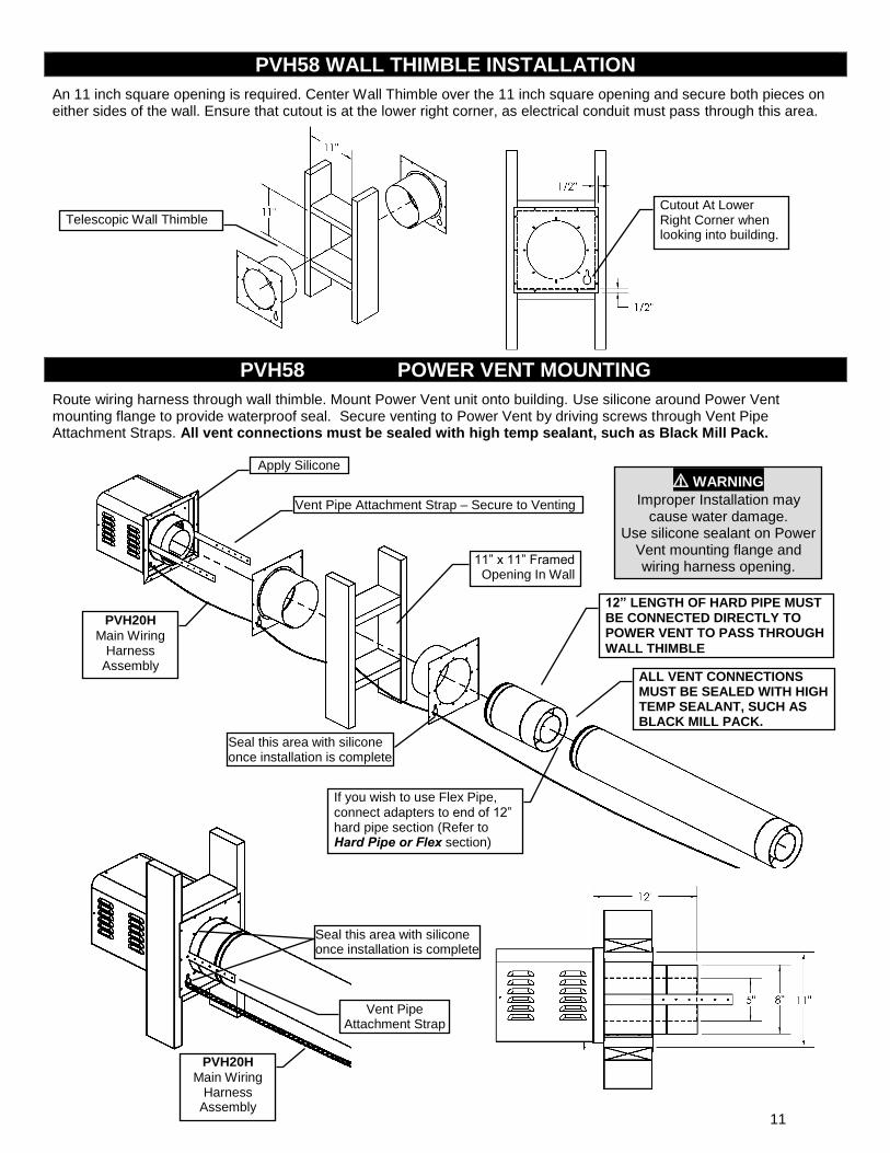
PVH58 WALL THIMBLE INSTALLATION
An 11 inch square opening is required. Center Wall Thimble over the 11 inch square opening and secure both pieces on either sides of the wall. Ensure that cutout is at the lower right corner, as electrical conduit must pass through this area.
PVH58 POWER VENT MOUNTING
Route wiring harness through wall thimble. Mount Power Vent unit onto building. Use silicone around Power Vent mounting flange to provide waterproof seal. Secure venting to Power Vent by driving screws through Vent Pipe Attachment Straps. All vent connections must be sealed with high temp sealant, such as Black Mill Pack.
Cutout At Lower Right Corner when looking into building.
Telescopic Wall Thimble
11” x 11” Framed Opening In Wall
Apply Silicone
12” LENGTH OF HARD PIPE MUST BE CONNECTED DIRECTLY TO POWER VENT TO PASS THROUGH
WALL THIMBLE
PVH20H
Main Wiring Harness
Assembly
Vent Pipe Attachment Strap – Secure to Venting
ALL VENT CONNECTIONS MUST BE SEALED WITH HIGH TEMP SEALANT, SUCH AS BLACK MILL PACK.
Seal this area with silicone once installation is complete
⚠ WARNING
Improper Installation may cause water damage.
Use silicone sealant on Power Vent mounting flange and wiring harness opening.
Seal this area with silicone once installation is complete
Vent Pipe Attachment Strap
If you wish to use Flex Pipe, connect adapters to end of 12” hard pipe section (Refer to Hard Pipe or Flex section)
PVH20H
Main Wiring Harness
Assembly 11
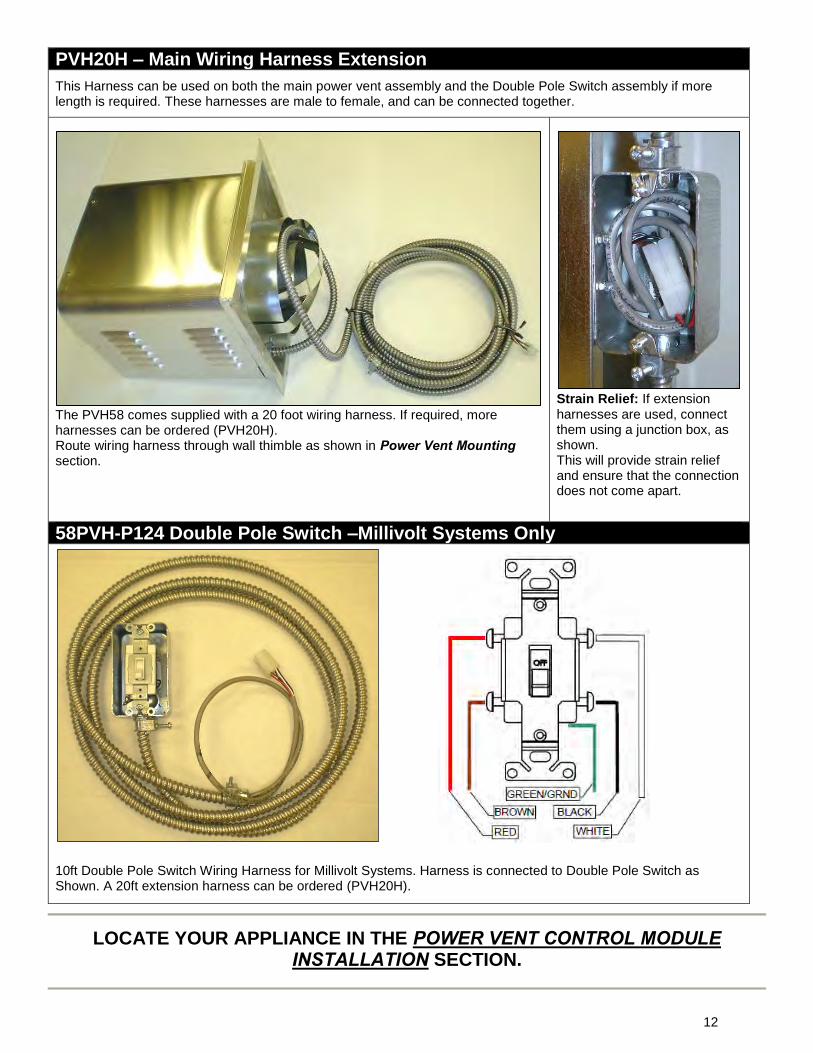
PVH20H – Main Wiring Harness Extension
This Harness can be used on both the main power vent assembly and the Double Pole Switch assembly if more length is required. These harnesses are male to female, and can be connected together.
The PVH58 comes supplied with a 20 foot wiring harness. If required, more harnesses can be ordered (PVH20H). Route wiring harness through wall thimble as shown in Power Vent Mounting section.
Strain Relief: If extension harnesses are used, connect them using a junction box, as shown. This will provide strain relief and ensure that the connection does not come apart.
58PVH-P124 Double Pole Switch –Millivolt Systems Only
10ft Double Pole Switch Wiring Harness for Millivolt Systems. Harness is connected to Double Pole Switch as Shown. A 20ft extension harness can be ordered (PVH20H).
LOCATE YOUR APPLIANCE IN THE POWER VENT CONTROL MODULE INSTALLATION SECTION.
12
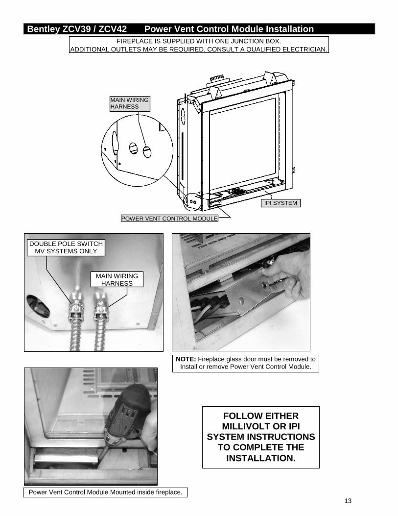
Bentley ZCV39 / ZCV42 Power Vent Control Module Installation
FIREPLACE IS SUPPLIED WITH ONE JUNCTION BOX. ADDITIONAL OUTLETS MAY BE REQUIRED. CONSULT A QUALIFIED ELECTRICIAN.
MAIN WIRING HARNESS
DOUBLE POLE SWITCH MV SYSTEMS ONLY
IPI SYSTEM
MAIN WIRING HARNESS
POWER VENT CONTROL MODULE
NOTE: Fireplace glass door must be removed to Install or remove Power Vent Control Module.
FOLLOW EITHER MILLIVOLT OR IPI
SYSTEM INSTRUCTIONS TO COMPLETE THE
INSTALLATION.
Power Vent Control Module Mounted inside fireplace. 13
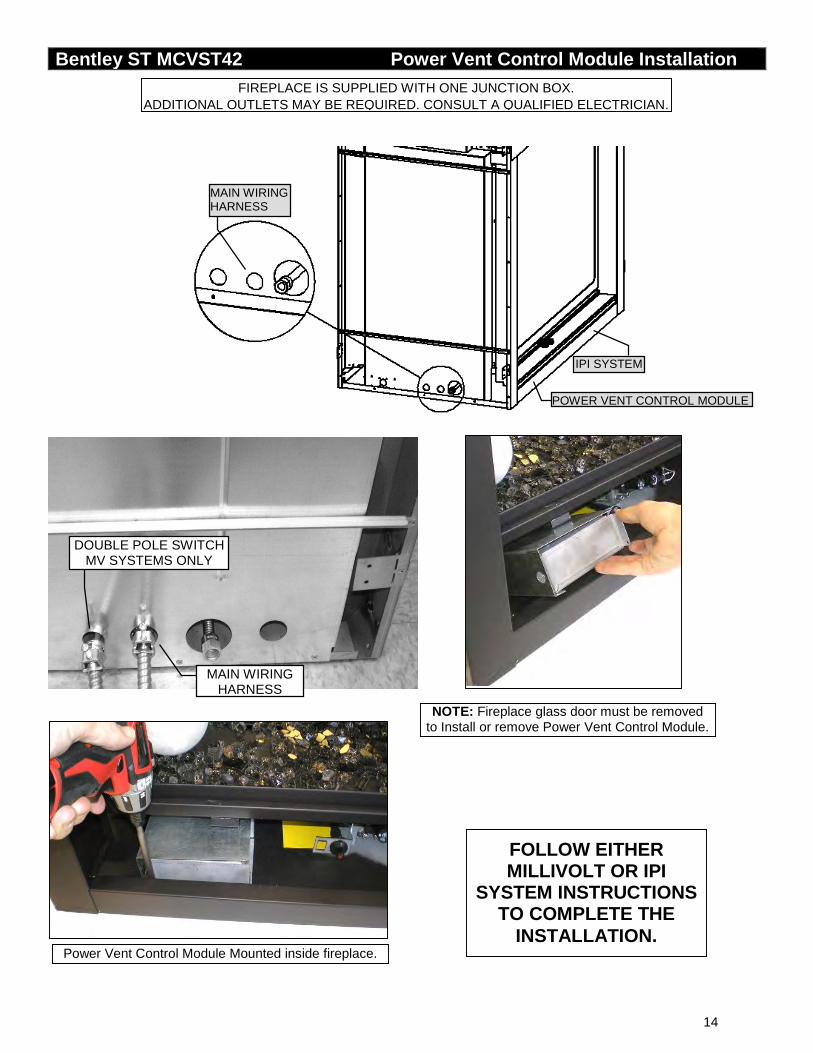
Bentley ST MCVST42 Power Vent Control Module Installation
FIREPLACE IS SUPPLIED WITH ONE JUNCTION BOX. ADDITIONAL OUTLETS MAY BE REQUIRED. CONSULT A QUALIFIED ELECTRICIAN.
Power Vent Control Module Mounted inside fireplace.
NOTE: Fireplace glass door must be removed to Install or remove Power Vent Control Module.
MAIN WIRING HARNESS
POWER VENT CONTROL MODULE
IPI SYSTEM
MAIN WIRING HARNESS
DOUBLE POLE SWITCH MV SYSTEMS ONLY
FOLLOW EITHER MILLIVOLT OR IPI
SYSTEM INSTRUCTIONS TO COMPLETE THE
INSTALLATION.
14
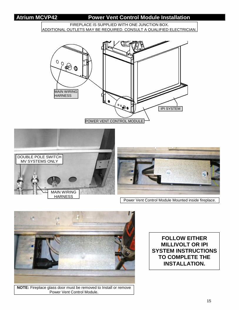
Atrium MCVP42 Power Vent Control Module Installation
FIREPLACE IS SUPPLIED WITH ONE JUNCTION BOX. ADDITIONAL OUTLETS MAY BE REQUIRED. CONSULT A QUALIFIED ELECTRICIAN.
NOTE: Fireplace glass door must be removed to Install or remove Power Vent Control Module.
Power Vent Control Module Mounted inside fireplace.
IPI SYSTEM
POWER VENT CONTROL MODULE
MAIN WIRING HARNESS
MAIN WIRING HARNESS
DOUBLE POLE SWITCH MV SYSTEMS ONLY
FOLLOW EITHER MILLIVOLT OR IPI
SYSTEM INSTRUCTIONS TO COMPLETE THE
INSTALLATION.
15
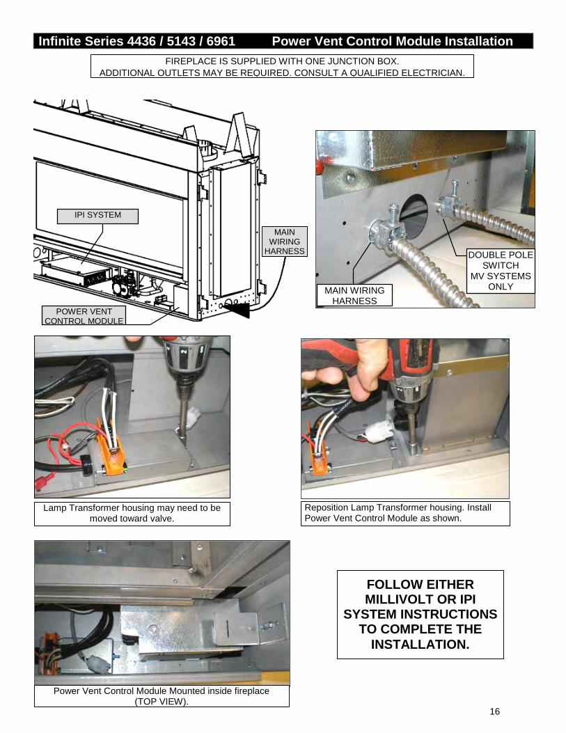
Infinite Series 4436 / 5143 / 6961 Power Vent Control Module Installation
FIREPLACE IS SUPPLIED WITH ONE JUNCTION BOX. ADDITIONAL OUTLETS MAY BE REQUIRED. CONSULT A QUALIFIED ELECTRICIAN.
MAIN WIRING
HARNESS
POWER VENT CONTROL MODULE
Lamp Transformer housing may need to be moved toward valve.
Reposition Lamp Transformer housing. Install Power Vent Control Module as shown.
Power Vent Control Module Mounted inside fireplace (TOP VIEW).
IPI SYSTEM
DOUBLE POLE SWITCH
MV SYSTEMS ONLY MAIN WIRING
HARNESS
FOLLOW EITHER MILLIVOLT OR IPI
SYSTEM INSTRUCTIONS TO COMPLETE THE
INSTALLATION.
16
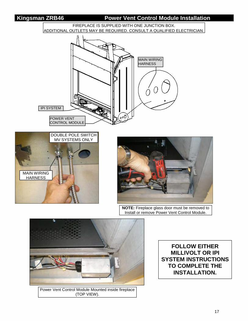
Kingsman ZRB46 Power Vent Control Module Installation
FIREPLACE IS SUPPLIED WITH ONE JUNCTION BOX. ADDITIONAL OUTLETS MAY BE REQUIRED. CONSULT A QUALIFIED ELECTRICIAN.
MAIN WIRING HARNESS
IPI SYSTEM
POWER VENT CONTROL MODULE
DOUBLE POLE SWITCH MV SYSTEMS ONLY
MAIN WIRING HARNESS
Power Vent Control Module Mounted inside fireplace (TOP VIEW).
NOTE: Fireplace glass door must be removed to Install or remove Power Vent Control Module.
FOLLOW EITHER MILLIVOLT OR IPI
SYSTEM INSTRUCTIONS TO COMPLETE THE
INSTALLATION.
17
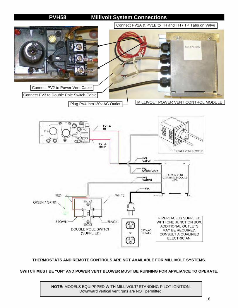
PVH58 Millivolt System Connections
THERMOSTATS AND REMOTE CONTROLS ARE NOT AVAILABLE FOR MILLIVOLT SYSTEMS.
SWITCH MUST BE “ON” AND POWER VENT BLOWER MUST BE RUNNING FOR APPLIANCE TO OPERATE.
MILLIVOLT POWER VENT CONTROL MODULE
Connect PV1A & PV1B to TH and TH / TP Tabs on Valve
Connect PV2 to Power Vent Cable
Connect PV3 to Double Pole Switch Cable
Plug PV4 into120v AC Outlet
NOTE: MODELS EQUIPPPED WITH MILLIVOLT/ STANDING PILOT IGNITION: Downward vertical vent runs are NOT permitted.
DOUBLE POLE SWITCH (SUPPLIED)
FIREPLACE IS SUPPLIED WITH ONE JUNCTION BOX.
ADDITIONAL OUTLETS MAY BE REQUIRED.
CONSULT A QUALIFIED ELECTRICIAN.
18
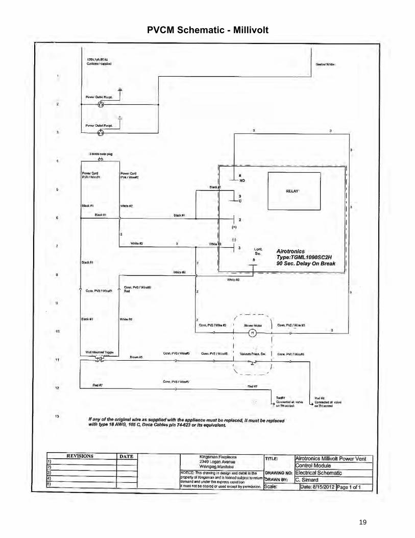
PVCM Schematic - Millivolt
19
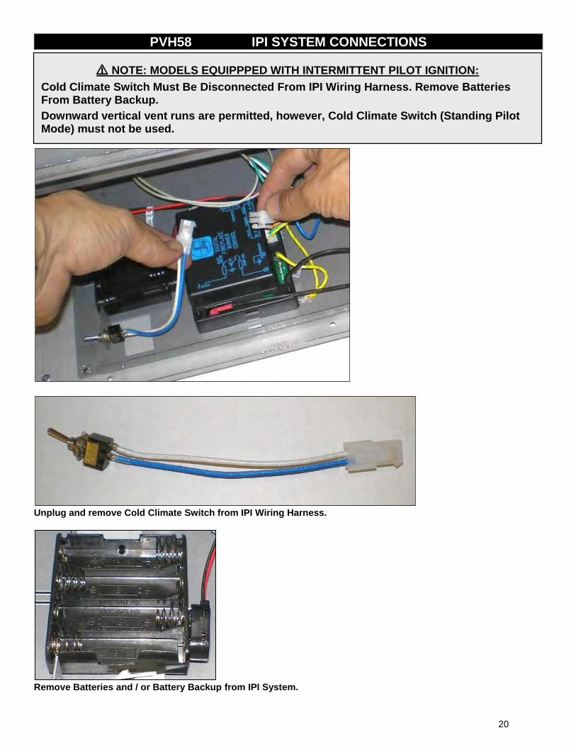
PVH58 IPI SYSTEM CONNECTIONS
Unplug and remove Cold Climate Switch from IPI Wiring Harness.
Remove Batteries and / or Battery Backup from IPI System.
⚠ NOTE: MODELS EQUIPPPED WITH INTERMITTENT PILOT IGNITION:
Cold Climate Switch Must Be Disconnected From IPI Wiring Harness. Remove Batteries From Battery Backup.
Downward vertical vent runs are permitted, however, Cold Climate Switch (Standing Pilot Mode) must not be used.
20
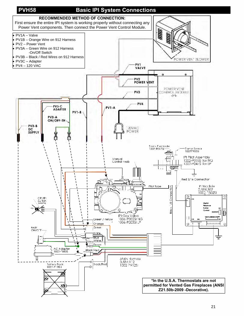
PVH58 Basic IPI System Connections RECOMMENDED METHOD OF CONNECTION:
First ensure the entire IPI system is working properly without connecting any Power Vent components. Then connect the Power Vent Control Module.
PV1A – Valve PV1B – Orange Wire on 912 Harness PV2 – Power Vent PV3A – Green Wire on 912 Harness -On/Off Switch PV3B – Black / Red Wires on 912 Harness PV3C – Adapter PV4 – 120 VAC
*In the U.S.A. Thermostats are not permitted for Vented Gas Fireplaces (ANSI
Z21.50b-2009 -Decorative).
21
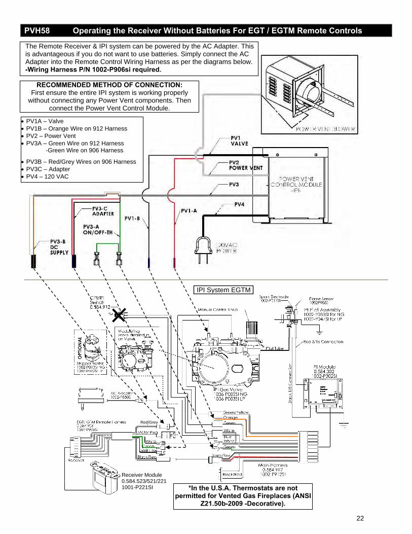
PVH58 Operating the Receiver Without Batteries For EGT / EGTM Remote Controls
The Remote Receiver & IPI system can be powered by the AC Adapter. This is advantageous if you do not want to use batteries. Simply connect the AC Adapter into the Remote Control Wiring Harness as per the diagrams below. -Wiring Harness P/N 1002-P906si required.
RECOMMENDED METHOD OF CONNECTION: First ensure the entire IPI system is working properly
without connecting any Power Vent components. Then connect the Power Vent Control Module.
PV1A – Valve PV1B – Orange Wire on 912 Harness PV2 – Power Vent PV3A – Green Wire on 912 Harness -Green Wire on 906 Harness
PV3B – Red/Grey Wires on 906 Harness PV3C – Adapter PV4 – 120 VAC
IPI System EGTM
Red/Grey
Receiver Module 0.584.523/521/2211001-P221SI *In the U.S.A. Thermostats are not
permitted for Vented Gas Fireplaces (ANSI Z21.50b-2009 -Decorative).
22
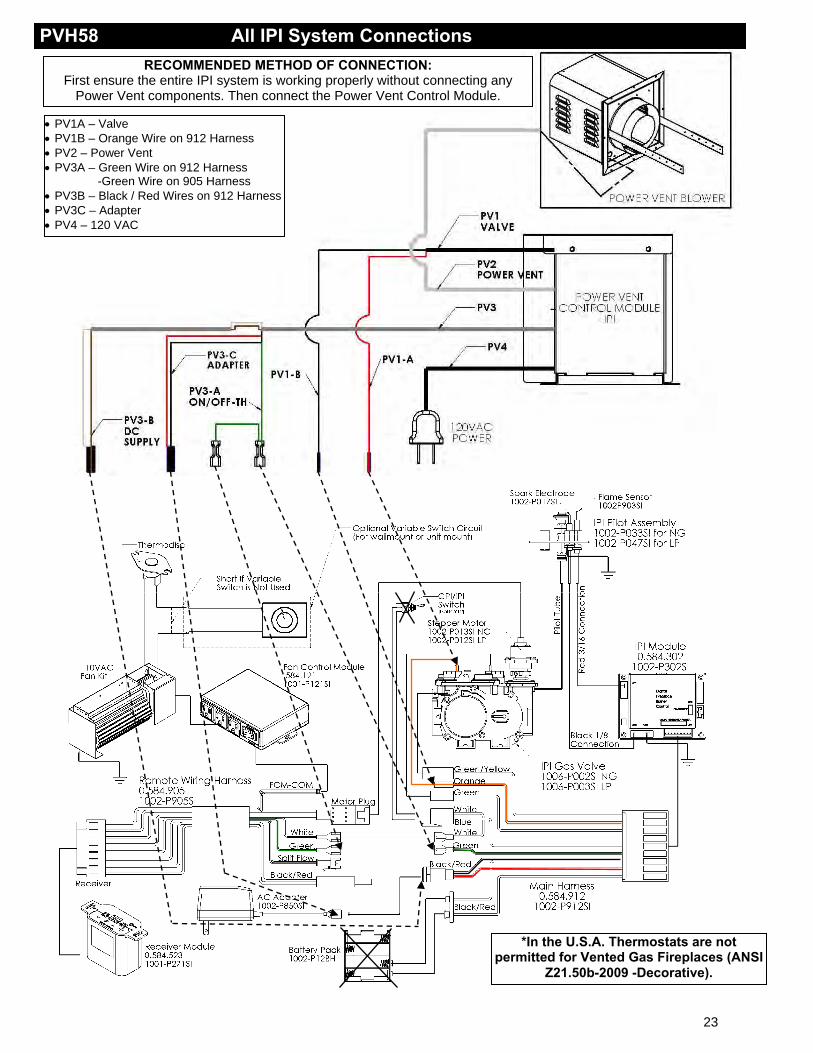
PVH58 All IPI System Connections RECOMMENDED METHOD OF CONNECTION:
First ensure the entire IPI system is working properly without connecting any Power Vent components. Then connect the Power Vent Control Module.
PV1A – Valve PV1B – Orange Wire on 912 Harness PV2 – Power Vent PV3A – Green Wire on 912 Harness -Green Wire on 905 Harness PV3B – Black / Red Wires on 912 Harness PV3C – Adapter PV4 – 120 VAC
*In the U.S.A. Thermostats are not permitted for Vented Gas Fireplaces (ANSI
Z21.50b-2009 -Decorative).
23
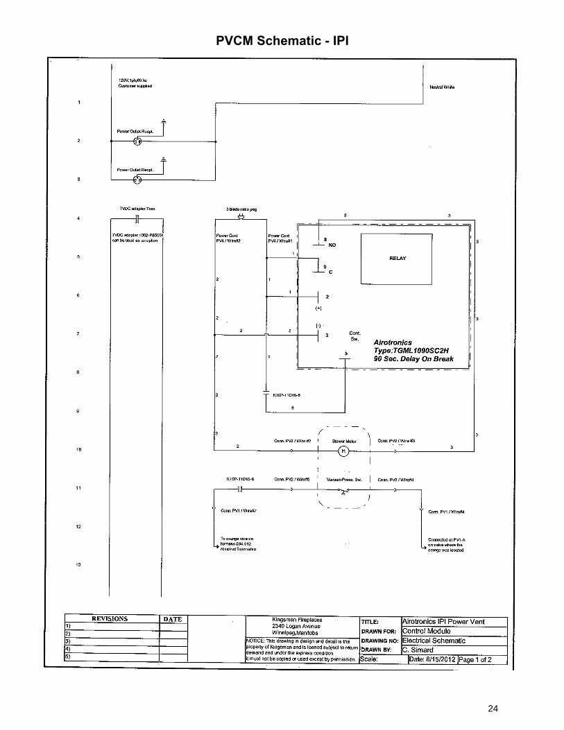
PVCM Schematic - IPI
24
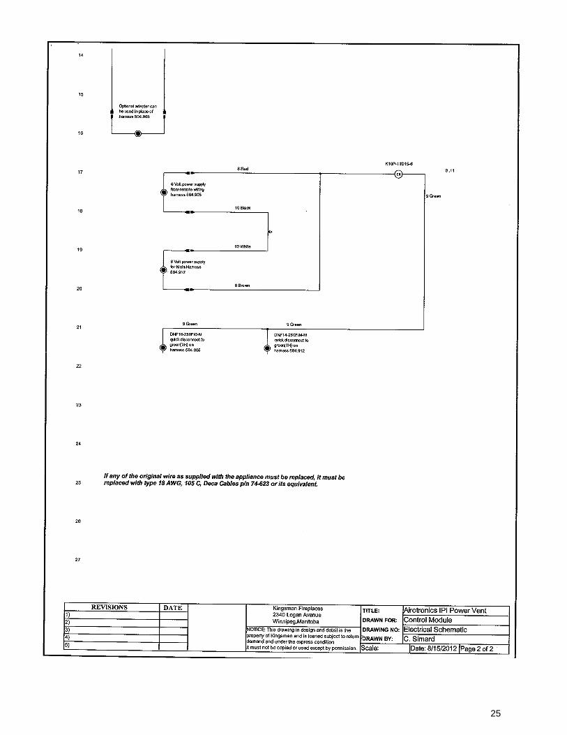
25
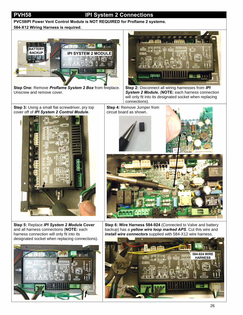
PVH58 IPI System 2 Connections PVC58IPI Power Vent Control Module is NOT REQUIRED for Proflame 2 systems. 584-X12 Wiring Harness is required.
Step One: Remove Proflame System 2 Box from fireplace. Unscrew and remove cover.
Step 2: Disconnect all wiring harnesses from IPI System 2 Module. (NOTE: each harness connection will only fit into its designated socket when replacing connections).
Step 3: Using a small flat screwdriver, pry top cover off of IPI System 2 Control Module.
Step 4: Remove Jumper from circuit board as shown.
Step 5: Replace IPI System 2 Module Cover and all harness connections (NOTE: each harness connection will only fit into its designated socket when replacing connections).
Step 6: Wire Harness 584-924 (Connected to Valve and battery backup) has a yellow wire loop marked APS. Cut this wire and install wire connectors supplied with 584-X12 wire harness.
IPI SYSTEM 2 MODULE
584-924 WIRE HARNESS
BATTERY BACKUP
26
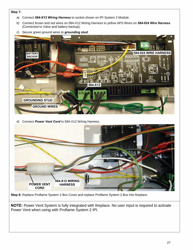
Step 7: a) Connect 584-X12 Wiring Harness to socket shown on IPI System 2 Module.
b) Connect brown and red wires on 584-X12 Wiring Harness to yellow APS Wires on 584-924 Wire Harness (Connected to Valve and battery backup).
c) Secure green ground wires to grounding stud.
d) Connect Power Vent Cord to 584-X12 Wiring Harness.
Step 8: Replace Proflame System 2 Box Cover and replace Proflame System 2 Box into fireplace.
NOTE: Power Vent System is fully integrated with fireplace. No user input is required to activate Power Vent when using with Proflame System 2 IPI.
584-X12
584-924 WIRE HARNESS
POWER VENT CORD
584-X12 WIRING HARNESS
GROUNDING STUD
GROUND WIRES
BATTERY BACKUP
27
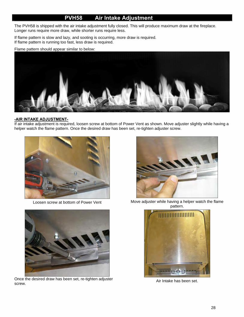
PVH58 Air Intake Adjustment The PVH58 is shipped with the air intake adjustment fully closed. This will produce maximum draw at the fireplace. Longer runs require more draw, while shorter runs require less.
If flame pattern is slow and lazy, and sooting is occurring, more draw is required. If flame pattern is running too fast, less draw is required.
Flame pattern should appear similar to below:
-AIR INTAKE ADJUSTMENT- If air intake adjustment is required, loosen screw at bottom of Power Vent as shown. Move adjuster slightly while having a helper watch the flame pattern. Once the desired draw has been set, re-tighten adjuster screw.
Loosen screw at bottom of Power Vent
Move adjuster while having a helper watch the flame
pattern.
Once the desired draw has been set, re-tighten adjuster screw.
Air Intake has been set.
28
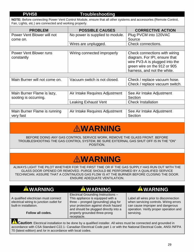
PVH58 Troubleshooting
NOTE: Before connecting Power Vent Control Module, ensure that all other systems and accessories (Remote Control, Fan, Lights, etc.) are connected and working properly.
PROBLEM POSSIBLE CAUSES CORRECTIVE ACTION
Power Vent Blower will not come on.
No power is supplied to module. Plug PVCM into 120VAC Source
Wires are unplugged. Check connections. Power Vent Blower runs constantly
Wiring connected improperly Check connections with wiring diagram. For IPI, ensure that wire PV3-A is plugged into the green wire on the 912 or 905 harness, and not the white.
Main Burner will not come on. Vacuum switch is not closed. Check / replace vacuum hose.
Check / replace vacuum switch. Main Burner Flame is lazy, sooting is occurring.
Air Intake Requires Adjustment See Air Intake Adjustment Section
Leaking Exhaust Vent Check Installation Main Burner Flame is running very fast
Air Intake Requires Adjustment See Air Intake Adjustment Section
⚠WARNING BEFORE DOING ANY GAS CONTROL SERVICE WORK, REMOVE THE GLASS FRONT. BEFORE
TROUBLESHOOTING THE GAS CONTROL SYSTEM, BE SURE EXTERNAL GAS SHUT OFF IS IN THE "ON" POSITION.
⚠WARNING ALWAYS LIGHT THE PILOT WHETHER FOR THE FIRST TIME OR IF THE GAS SUPPLY HAS RUN OUT WITH THE
GLASS DOOR OPENED OR REMOVED. PURGE SHOULD BE PERFORMED BY A QUALIFIED SERVICE TECHNICIAN. ASSURE THAT A CONTINUOUS GAS FLOW IS AT THE BURNER BEFORE CLOSING THE DOOR.
ENSURE ADEQUATE VENTILATION.
WARNING WARNING WARNING A qualified electrician must connect electrical wiring to junction outlet for built-in installation.
Follow all codes.
Electrical Grounding Instructions – This appliance is equipped with a three – pronged (grounding) plug for your protection against shock hazard and should be plugged directly into a properly grounded three-prong receptacle.
Label all wires prior to disconnection when servicing controls. Wiring errors can cause improper and dangerous operation. Verify proper operation and servicing.
Caution: Electrical installation to be done by a qualified installer. All wires must be connected and grounded in accordance with CSA Standard C22.1- Canadian Electrical Code part 1 or with the National Electrical Code, ANSI /NFPA 70 (latest edition) and /or in accordance with local codes.
29
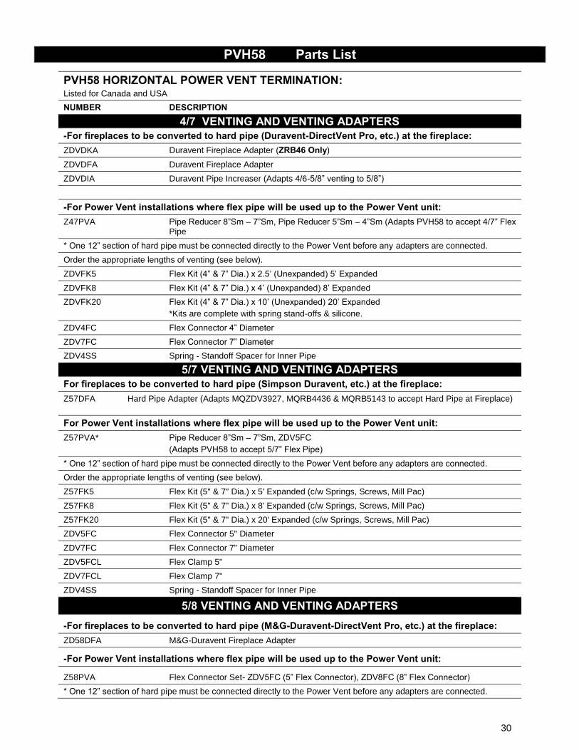
PVH58 Parts List
PVH58 HORIZONTAL POWER VENT TERMINATION: Listed for Canada and USA NUMBER DESCRIPTION
4/7 VENTING AND VENTING ADAPTERS -For fireplaces to be converted to hard pipe (Duravent-DirectVent Pro, etc.) at the fireplace: ZDVDKA Duravent Fireplace Adapter (ZRB46 Only)
ZDVDFA Duravent Fireplace Adapter
ZDVDIA Duravent Pipe Increaser (Adapts 4/6-5/8” venting to 5/8”)
-For Power Vent installations where flex pipe will be used up to the Power Vent unit: Z47PVA Pipe Reducer 8”Sm – 7”Sm, Pipe Reducer 5”Sm – 4”Sm (Adapts PVH58 to accept 4/7” Flex
Pipe
* One 12” section of hard pipe must be connected directly to the Power Vent before any adapters are connected.
Order the appropriate lengths of venting (see below).
ZDVFK5 Flex Kit (4” & 7” Dia.) x 2.5’ (Unexpanded) 5’ Expanded
ZDVFK8 Flex Kit (4” & 7” Dia.) x 4’ (Unexpanded) 8’ Expanded
ZDVFK20 Flex Kit (4” & 7” Dia.) x 10’ (Unexpanded) 20’ Expanded *Kits are complete with spring stand-offs & silicone.
ZDV4FC Flex Connector 4” Diameter
ZDV7FC Flex Connector 7” Diameter
ZDV4SS Spring - Standoff Spacer for Inner Pipe
5/7 VENTING AND VENTING ADAPTERS For fireplaces to be converted to hard pipe (Simpson Duravent, etc.) at the fireplace: Z57DFA
Hard Pipe Adapter (Adapts MQZDV3927, MQRB4436 & MQRB5143 to accept Hard Pipe at Fireplace)
For Power Vent installations where flex pipe will be used up to the Power Vent unit: Z57PVA* Pipe Reducer 8”Sm – 7”Sm, ZDV5FC
(Adapts PVH58 to accept 5/7” Flex Pipe)
* One 12” section of hard pipe must be connected directly to the Power Vent before any adapters are connected.
Order the appropriate lengths of venting (see below).
Z57FK5 Flex Kit (5" & 7" Dia.) x 5' Expanded (c/w Springs, Screws, Mill Pac)
Z57FK8 Flex Kit (5" & 7" Dia.) x 8' Expanded (c/w Springs, Screws, Mill Pac)
Z57FK20 Flex Kit (5" & 7" Dia.) x 20' Expanded (c/w Springs, Screws, Mill Pac)
ZDV5FC Flex Connector 5" Diameter
ZDV7FC Flex Connector 7" Diameter
ZDV5FCL Flex Clamp 5"
ZDV7FCL Flex Clamp 7"
ZDV4SS Spring - Standoff Spacer for Inner Pipe
5/8 VENTING AND VENTING ADAPTERS -For fireplaces to be converted to hard pipe (M&G-Duravent-DirectVent Pro, etc.) at the fireplace: ZD58DFA M&G-Duravent Fireplace Adapter
-For Power Vent installations where flex pipe will be used up to the Power Vent unit:
Z58PVA Flex Connector Set- ZDV5FC (5” Flex Connector), ZDV8FC (8” Flex Connector)
* One 12” section of hard pipe must be connected directly to the Power Vent before any adapters are connected.
30
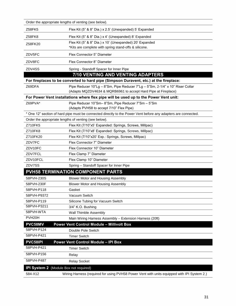
Order the appropriate lengths of venting (see below).
Z58FK5 Flex Kit (5” & 8” Dia.) x 2.5’ (Unexpanded) 5’ Expanded
Z58FK8 Flex Kit (5” & 8” Dia.) x 4’ (Unexpanded) 8’ Expanded
Z58FK20 Flex Kit (5” & 8” Dia.) x 10’ (Unexpanded) 20’ Expanded *Kits are complete with spring stand-offs & silicone.
ZDV5FC Flex Connector 5” Diameter
ZDV8FC Flex Connector 8” Diameter
ZDV4SS Spring - Standoff Spacer for Inner Pipe
7/10 VENTING AND VENTING ADAPTERS For fireplaces to be converted to hard pipe (Simpson Duravent, etc.) at the fireplace: Z69DFA Pipe Reducer 10”Lg – 8”Sm, Pipe Reducer 7”Lg – 5”Sm, 2-1/4” x 10” Riser Collar
(Adapts MQZDV4634 & MQRB6961 to accept Hard Pipe at Fireplace)
For Power Vent installations where flex pipe will be used up to the Power Vent unit: Z69PVA* Pipe Reducer 10”Sm– 8”Sm, Pipe Reducer 7”Sm – 5”Sm
(Adapts PVH58 to accept 7/10” Flex Pipe)
* One 12” section of hard pipe must be connected directly to the Power Vent before any adapters are connected.
Order the appropriate lengths of venting (see below).
Z710FK5 Flex Kit (7/10”x5’ Expanded: Springs, Screws, Millpac)
Z710FK8 Flex Kit (7/10”x8’ Expanded: Springs, Screws, Millpac)
Z710FK20 Flex Kit (7/10”x20’ Exp.: Springs, Screws, Millpac)
ZDV7FC Flex Connector 7” Diameter
ZDV10FC Flex Connector 10” Diameter
ZDV7FCL Flex Clamp 7” Diameter
ZDV10FCL Flex Clamp 10” Diameter
ZDV7SS Spring – Standoff Spacer for Inner Pipe
PVH58 TERMINATION COMPONENT PARTS 58PVH-230S Blower Motor and Housing Assembly
58PVH-230F Blower Motor and Housing Assembly
58PVH-P118 Gasket
58PVH-P9372 Vacuum Switch
58PVH-P119 Silicone Tubing for Vacuum Switch
58PVH-P3211 3/4” K.O. Bushing
58PVH-WTA Wall Thimble Assembly
PVH20H Main Wiring Harness Assembly – Extension Harness (20ft)
PVC58MV Power Vent Control Module – Millivolt Box 58PVH-P124 Double Pole Switch
58PVH-P421 Timer Switch
PVC58IPI Power Vent Control Module – IPI Box 58PVH-P421 Timer Switch
58PVH-P156 Relay
58PVH-P487 Relay Socket
IPI System 2 (Module Box not required) 584-X12 Wiring Harness (required for using PVH58 Power Vent with units equipped with IPI System 2.)
31
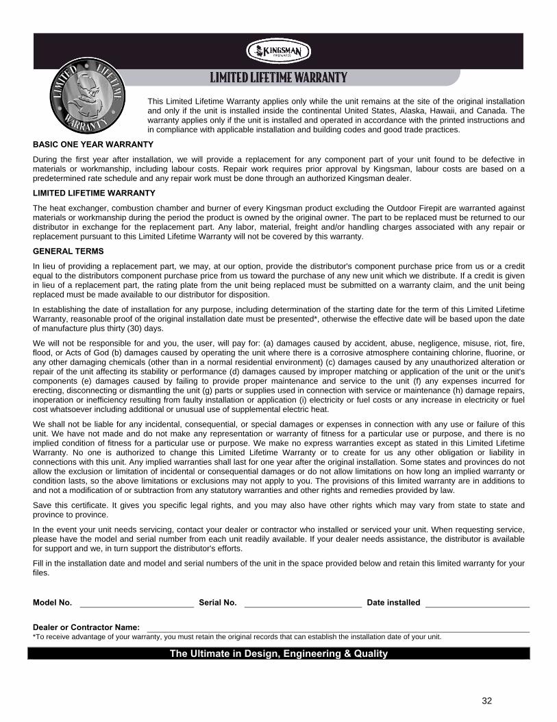
This Limited Lifetime Warranty applies only while the unit remains at the site of the original installation and only if the unit is installed inside the continental United States, Alaska, Hawaii, and Canada. The warranty applies only if the unit is installed and operated in accordance with the printed instructions and in compliance with applicable installation and building codes and good trade practices.
BASIC ONE YEAR WARRANTY
During the first year after installation, we will provide a replacement for any component part of your unit found to be defective in materials or workmanship, including labour costs. Repair work requires prior approval by Kingsman, labour costs are based on a predetermined rate schedule and any repair work must be done through an authorized Kingsman dealer.
LIMITED LIFETIME WARRANTY
The heat exchanger, combustion chamber and burner of every Kingsman product excluding the Outdoor Firepit are warranted against materials or workmanship during the period the product is owned by the original owner. The part to be replaced must be returned to our distributor in exchange for the replacement part. Any labor, material, freight and/or handling charges associated with any repair or replacement pursuant to this Limited Lifetime Warranty will not be covered by this warranty.
GENERAL TERMS
In lieu of providing a replacement part, we may, at our option, provide the distributor's component purchase price from us or a credit equal to the distributors component purchase price from us toward the purchase of any new unit which we distribute. If a credit is given in lieu of a replacement part, the rating plate from the unit being replaced must be submitted on a warranty claim, and the unit being replaced must be made available to our distributor for disposition.
In establishing the date of installation for any purpose, including determination of the starting date for the term of this Limited Lifetime Warranty, reasonable proof of the original installation date must be presented*, otherwise the effective date will be based upon the date of manufacture plus thirty (30) days.
We will not be responsible for and you, the user, will pay for: (a) damages caused by accident, abuse, negligence, misuse, riot, fire, flood, or Acts of God (b) damages caused by operating the unit where there is a corrosive atmosphere containing chlorine, fluorine, or any other damaging chemicals (other than in a normal residential environment) (c) damages caused by any unauthorized alteration or repair of the unit affecting its stability or performance (d) damages caused by improper matching or application of the unit or the unit's components (e) damages caused by failing to provide proper maintenance and service to the unit (f) any expenses incurred for erecting, disconnecting or dismantling the unit (g) parts or supplies used in connection with service or maintenance (h) damage repairs, inoperation or inefficiency resulting from faulty installation or application (i) electricity or fuel costs or any increase in electricity or fuel cost whatsoever including additional or unusual use of supplemental electric heat.
We shall not be liable for any incidental, consequential, or special damages or expenses in connection with any use or failure of this unit. We have not made and do not make any representation or warranty of fitness for a particular use or purpose, and there is no implied condition of fitness for a particular use or purpose. We make no express warranties except as stated in this Limited Lifetime Warranty. No one is authorized to change this Limited Lifetime Warranty or to create for us any other obligation or liability in connections with this unit. Any implied warranties shall last for one year after the original installation. Some states and provinces do not allow the exclusion or limitation of incidental or consequential damages or do not allow limitations on how long an implied warranty or condition lasts, so the above limitations or exclusions may not apply to you. The provisions of this limited warranty are in additions to and not a modification of or subtraction from any statutory warranties and other rights and remedies provided by law.
Save this certificate. It gives you specific legal rights, and you may also have other rights which may vary from state to state and province to province.
In the event your unit needs servicing, contact your dealer or contractor who installed or serviced your unit. When requesting service, please have the model and serial number from each unit readily available. If your dealer needs assistance, the distributor is available for support and we, in turn support the distributor's efforts.
Fill in the installation date and model and serial numbers of the unit in the space provided below and retain this limited warranty for your files.
Model No. Serial No. Date installed
Dealer or Contractor Name: *To receive advantage of your warranty, you must retain the original records that can establish the installation date of your unit.
The Ultimate in Design, Engineering & Quality
32