Embed Size (px)
Citation preview

INSTALLATION, OPERATINGAND SERVICE INSTRUCTIONS
FR "rMSERIES
HORIZONTAL TUBE BOILER
For service or repairs to boiler, call your heating contractor. When seeking information onboiler, provide Boiler Model Number and Serial Number as shown on Rating Label.
Boiler Model Number Boiler Serial Number Installation Date
FR
Heating Contractor Phone Number
Address
8147202R5-7/07
®
RESIDENTIAL HEATING BOILERS
Price - $3.00

IMPORTANT INFORMATION - READ CAREFULLY
All boilers must be installed in accordance with National, State and Local Plumbing,Heating and Electrical Codes and the regulations of the serving utilities. These
Codes and Regulations may differ from this instruction manual. Authorities havingjurisdiction should be consulted before installations are made.In all cases, reference should be made to the following Standards:
A. All wiring on boilers shall be made in accordance with the National Electrical
Code and/or Local Regulations.B. Current Edition of American National Standard ANSI/NFPA 31, "Installation of Oil
Burning Equipment", for recommended installation practices.C. Current Edition of American National Standard ANSI/NFPA211, "Chimneys,
Fireplaces, Vents, and Solid Fuel Burning Appliances", For Venting requirements.
D. Current Edition of American Society of Mechanical Engineers ASME CSD-1,"Controls and Safety Devices for Automatically Fired Boilers", for assembly andoperations of controls and safety devices.
The following terms are used throughout this manual to bring attention to the presence of hazards of various risk levels,or to important information concerning product life.
Indicates an imminently hazardous situationwhich, if not avoided, will result in death,serious injury or substantial propertydamage.
Indicates a potentially hazardous situationwhich, if not avoided, may result in moderateor minor injury or property damage.
Indicates a potentially hazardous situationwhich, if not avoided, could result in death,serious injury or substantial propertydamage.
lndicates special instructions on installation,operation, or maintenance which areimportant but not related to personal injury
hazards.
This boiler has a limited warranty, a copy of which is printed on the back of this manual.It is the responsibility of the installing contractor to see that all controls are correctly installedand are operating properly when the installation is complete. The warranty for this boiler isvalid only if the boiler has been installed, maintained and operated in accordance with theseinstructions.
2
DO NOT store or use gasoline or other flammable vapors or liquids in the vicinity of this or anyother appliance.
Improper installation, adjustment, alteration, service or maintenance can cause propertydamage, personal injury or loss of life. Failure to follow all instructions in the proper ordercan cause personal injury or death. Read and understand all instructions, including allthose contained in component manufacturers manuals which are provided with theappliance before installing, starting-up, operating, maintaining or servicing this appliance.Keep this manual and literature in legible condition and posted near appliance for referenceby owner and service technician.
This boiler requires regular maintenance and service to operate safely. Follow theinstructions contained in this manual. Installation, maintenance, and service must beperformed only by an experienced, skilled and knowledgeable installer or service agency. Allheating systems should be designed by competent contractors and only personsknowledgeable in the layout and installation of hydronic heating systems should attemptinstallation of any boiler. Itistheresponsibilityoftheinstallingcontractortoseethatallcontrols are correctly installed and are operating properly when the installation is completed.Installation is not complete unless a pressure relief valve is installed into the tapping locatedon top of appliance - See Section III of this manual for details.
This boiler is not suitable for installation on combustible flooring, unless installed with acombustible floor shield constructed in accordance with NFPA 31. Concrete over wood
joists is considered combustible flooring.Do not install boiler on carpeting.When boiler is installed on concrete which is over a material that is subject to melting(PVC, PEX radiant tubing, etc.) a combustible floor shield must be used.A concrete pad is not sufficient to protect combustible flooring.Do not operate on masonry floors, which may contain moisture.
Do not tamper with or alter the boiler or controls. Retain your contractor or a competentserviceman to assure that the unit is properly adjusted and maintained.Have Firetubes cleaned at least once a year - preferably at the start of the heating season toremove soot and scale. The inside of combustion chamber should also be cleaned and
inspected at the same time.Have Oil Burner and Controls checked at least once a year or as may be necessitated.Do not operate unit with jumpered or absent controls or safety devices.Do not operate unit if any control, switch, component, or device has been subject to water.
Appliance materials of construction, products of combustion and the fuel contain alumina,silica, heavy metals, carbon monoxide, nitrogen oxides, aldehydes and/or other toxic orharmful substances which can cause death or serious injury and which are known to thestate of California to cause cancer, birth defects and other reproductive harm. Always useproper safety clothing, respirators and equipment when servicing or working nearby theboiler.
This boiler is designed to burn No. 2 fuel oil only. Do not use gasoline, crankcase drainings, orany oil containing gasoline. Never burn garbage or paper in this boiler. Do not convert to anysolid fuel (i.e. wood, coal). Do not convert to any gaseous fuel (i.e. natural gas, LP). Allflammable debris, rags, paper, wood scraps, etc., should be kept clear of the boiler at all times.Keep the boiler area clean and free of fire hazards.

This boiler contains very hot water under high pressures. Do not unscrew any pipe fittings norattemptto disconnect anycomponentsof this boilerwithout positivelyassuring the water is cooland hasno pressure. Alwayswear protectiveclothing and equipment when installing, starting upor servicing this boiler to prevent scald injuries. Do not rely on the pressure and temperaturegauges to determine the temperature and pressure of the boiler. This boiler contains componentswhich become very hot when the boiler is operating. Do not touch any components unless theyare cool.
This appliance must be properly vented and connected to an approved vent system in goodcondition. Serious property damage could result if the boiler is connected to an unapproved ventsystem.
This boiler needs fresh air for safe operation and must be installed so there are provisions foradequate combustion and ventilation air.
The interior of the venting and air intake systems must be inspected and cleaned before the startof the heating season and should be inspected periodically throughout the heating season for anyobstructions. Clean and unobstructed venting and air intake systems are necessary to allownoxious fumes that could cause injury or loss of life to vent safely and will contribute towardmaintaining the boiler's efficiency.
This boiler is supplied with controls which may cause the boiler to shut down and not re-startwithout service. If damage due to frozen pipes is a possibility, the heating system shouldnot be left unatttended in cold weather; or appropriate safeguards and alarms should be installedon the heating system to prevent damage if the boiler is inoperative.
4

Table of Contents
I. Pre-Installation ............................... 6
II. Knockdown Boiler Assembly .......... 8
III. Water Piping and Trim ................. 10
IV. Venting ......................................... 15
V. Electrical ....................................... 16
VI°
VII.
VIII.
VIX.
X.
Oil Piping ..................................... 18
System Start-Up ............................ 20
Service and Cleaning .................... 27
Repair Parts .................................. 29
AppendixLowWater Cut Off ....................... 37
Figure 1: FR Packaged Boiler
BOILER
MODEL A B C E F G
FR-HGS 31-7/8 19-7/8 18-3/8 31-3/8 3-1/8 5-7/8
FR-HGS II 31-7/8 19-7/8 18-3/8 31-3/8 3-1/8 6-7/8
FR-98/122 37-7/8 19-7/8 18-3/8 30-1/2 3-7/8 5-7/8
FR-147/173 46-5/8 21-7/8 21-5/8 35-3/4 5-3/8 6-7/8
FR-205/232 46-5/8 21-7/8 25-7/8 40-3/4 6-1/8 7-7/8
FR-265/305 51-1/8 21-7/8 25-7/8 38-3/4 6-1/8 7-7/8
FR-350/400 58 25-7/8 27-7/8 40-7/8 6-1/8 9-7/8
FR-462 58 25-7/8 33-7/8 46-3/4 6-1/8 9-7/8
Dimensions -Inches
D
25-3/4
26-1/2
25-1/4
30-1/4
29-3/4
34
35-3/4
35-3/4

I. Pre-lnstallation
A.
B°
INSPECT SHIPMENT carefully for any signs ofdamage.
1. ALL EQUIPMENT is carefully lnanu_actured,inspected and packed. Our responsibility ceasesupon delivery of the crated boiler to the carrier ingood condition.
2. ANY CLAIMS for damage or shortage of shipmentmust filed immediately against the carrier bythe consignee. No claims for variances from,
or shortage in orders, will be allowed by thelnanufacturer unless presented within sixty (60) daysafter receipt of goods.
LOCATE BOILER in front of final position beforeremoving crate.
Do not drop boiler. Do not bump boiler jacketagainst floor.
1. LOCATE so that smoke pipe connection tochimney will be short and direct. BOILER ISNOT SUITABLE FOR INSTALLATION ONCOMBUSTIBLE FLOOR. DO NOT install on
carpeting.
2.
3.
FOR BASEMENT INSTALLATION, provide asolid base, such as concrete, if floor is not level, or ifwater may be encountered on floor around boiler.
PROVIDE SERVICE CLEARANCE of at least 48"
from the front of the jacket for servicing of burnerand removal of tankless heater.
For minilnuln clearances to combustible materials. See
Figure 2.
Do not support boiler by placing blocksat the four (4) corners of the boiler.Boiler base must be evenly supportedunder entire base.
Concrete over wood joists is consideredcombustible flooring. Do not operate onmasonry floors, which may containmoisture.
1.
2.
3.
FLOOR FLOOR
UNE LINE
Figure 2: Minimum Clearances to Combustible Materials
Listed clearances comply with American National Standard ANSI/NFPA 3l, Installation of Oil Burning Equipment.
FR TM boilers may be installed in rooms with clearances from combustible material as listed above. Listed clearances may notbe reduced for alcove or closet installations.
For reduced clearances to combustible material, protection must be provided as described in the above ANSI/NFPA 31standard.

Co PROVIDE COMBUSTION AND VENTILATION
AIR. Local code provisions may apply and should bereferenced.
Adequate combustion and ventilationair must be provided to assure propercombustion and to maintain safeambient air temperatures.
Do not install boiler where gasoline orother flammable vapors or liquids, orsources of hydrocarbons (i.e. bleaches,fabric softeners, etc.) are used orstored.
1. Determine volume of space (boiler room). Roomscolnlnunicating directly with the space in whichthe appliances are installed, through openings notfurnished with doors, are considered a part of thespace.
Volulne(ft 3) = Length(ft) x Width(ft) x Height(ft)
2. Determine total input of all appliances in the space.
Add inputs of all appliances in the space and roundthe result to the nearest 1000 BTU per hour.
3. Determine type of space. Divide Volume by totalinput of all appliances in space. If the result isgreater than or equal to 50 ft3/1000 BTU per hour,then it is considered an uncol_ned space. If theresult is less than 50 ft3/1000 BTU per hour then thespace is considered a co17finedspace.
4. For boiler located in an uncol?fined space of aconventionally constructed building, the freshair infiltration through cracks around windowsand doors normally provides adequate air forcombustion and ventilation.
5. For boiler located in a confined space or anunconfined space in a building of unusually tightconstruction, provide outdoor air with the use of twopermanent openings which colnlnunicate directly or
by duct with the outdoors or spaces (crawl or attic)freely colmnunicating with the outdoors. Locate oneopening within 12 inches of top of space. Locateremaining opening within 12 inches of bottom ofspace. Minimum dimension of air opening is 3inches. Size each opening per following:
a. Direct communication with outdoors.
Minimum free area of 1 square inch per 4,000BTU per hour input of all equipment in space.
b. Vertical ducts. Minimum free area of 1 squareinch per 4,000 BTU per hour input of allequipment in space. Duct cross-sectional areashall be same as opening free area.
c. Horizontal ducts. Minimum free area of 1
square inch per 2,000 BTU per hour input of allequipment in space. Duct cross-sectional areashall be same as opening free area.
Alternate method for boiler located withincol_ned space. Use indoor air if two permanentopenings colnlnunicate directly with additionalspace(s) of sufficient volume such that combinedvolume of all spaces meet criteria for unconfinedspace. Size each opening for minilnuln free areaof 1 square inch per 1,000 BTU per hour inputof all equipment in spaces, but not less than 100square inches.
6. Louvers and Grilles of Ventilation Ducts
All outside openings should be screened andlouvered. Screens used should not be smaller
than 1/4 inch mesh. Louvers will prevent theentrance of rain and snow.
b. Free area requirements need to consider theblocking effect of louvers, grilles, or screensprotecting the openings. If the free area of thelouver or grille is not known, assume woodlouvers have 20-25 percent free area and metallouvers and grilles have 60-75 percent free area.
c. Louvers and grilles must be fixed in the openposition, or interlocked with the equipment toopen automatically during equipment operation.
II. Knock-Down Boiler Assembly
A. REMOVAL OF BOILER.
1.
B.
2.
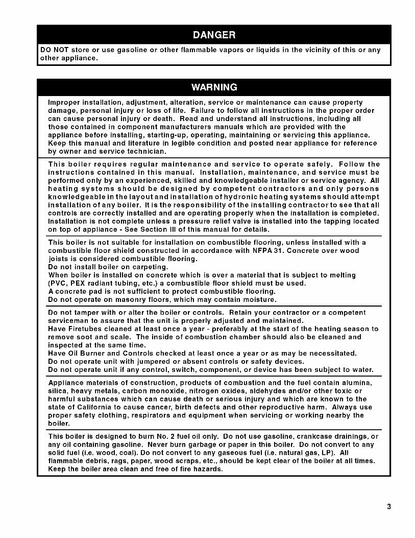
C. INSTALLING THE JACKET
1.Remove all boiler-to-skid hold down fasteners.
2.
FR-HGS thru FR-232: Carefully walk boiler to theedge of skid. Tilt the boiler back, allowing an edgeto rest on the floor, and remove the skid.
FR-265 thru FR-462: A mechanical lifting devicemay be required to safely remove boiler from skid.
TEST HEAT EXCHANGER FOR LEAKS before
proceeding with jacket assembly.
2.
Install pressure relief valve supplied, a hose to thecity water and a valve in the supply tapping. Plugremainder of tappings.
Fill boiler with water and apply a pressure of at least10 psig but no more than 30 psig.
If front flue box or rear smoke box fasteners
are removed, tighten them to 26 ft/Ibs whenreplacing them.
3.
Attach lower rear jacket panel to left side and rightside jacket panels with the screws provided so thatthe assembled components make a "U" shape andcan stand alone (see Figure 19).
Approaching the boiler from the rear, place theassembled jacket pieces from Step 1 around theboiler so that the lower rear panel passes below therear slnokebox.
Attach the lower front panel, upper front panel, andupper rear panel. Make sure the jacket clearanceholes line up properly with the appropriate boilerextensions and tappings.
4. Attach the top panel assembly (left and right pieces).
D. INSTALLATION OF BOILER CONTROLS
1.
2.
3.
Install provided pressure/temperature gauge into ¼"NPT coupling located on front or top of the boiler.Tighten so not to have any water leaks.
Mount the limit control. Thread the providedimmersion well into the 3/4"NPT tapping located onthe front or top of boiler. Place the aquastat controlwith sensing bulb on well so that bulb is insertedfully into well.
Mount burner to front fire door and wire accordingto instructions provided with the burner. Refer toFigure 3.

BURNER MOUNTING
W!KEYHOLE SLOTS
OIL, BURNER
Figure 3: Burner Mounting

III. Water Piping and Trim
Failure to properly pipe boiler may result in improper operation and damage to boiler or structure.
Oxygen contamination of boiler water will cause corrosion of iron and steel boiler components, andcan lead to boiler failure. New Yorker's Standard Warranty does not cover problems caused byoxygen contamination of boiler water or scale (lime) build-up caused by frequent addition of water.
A. DESIGN A PIPING SYSTEM and install boiler which
will prevent oxygen contamination of boiler water andfrequent water additions.
1. There are many possible causes of oxygencontamination such as:
a. Addition of excessive make-up water as a resultof system leaks.
b. Absorption through open tanks and fittings.
c. Oxygen permeable materials in the distributionsystem.
2. In order to insure long product life, oxygen sourcesshould be eliminated. This can be accomplished bytaking the following measures:
a. Repairing system leaks to eliminate the need foraddition of make-up water.
b. Eliminating open tanks from the system.
c. Eliminating and/or repairing fittings which allowoxygen absorption.
d. Use of non-permeable materials in thedistribution system.
e. Isolating the boiler from the system water byinstalling a heat exchanger.
System supply and return piping must beconnected to correct boiler pipe.
a. If this boiler is used in connection with
refrigeration systems, the boiler must be installedso that the chilled medium is piped in parallelwith the heating boiler using appropriate valvesto prevent the chilled medium from enteringthe boiler. See Figure 4. Also, consult I=B=RInstallation and Piping Guides.
@,WA T_R
/*i 2 ; t,
3}i}it.Y HA H iN _.4!_irJRN HA N _ R@b _
CDF!S N!II? _i:AT/N6 {DH}_ _q(_} !q£P:!T H@8, Cg@ ill@ 3Y3 @H 8_ C@ii!! NI;: 3Y8 _'_
Figure 4: Recommended Piping for CombinationHeating and Cooling (Refrigeration) System
10
New Yorker recommends sizing thesystem circulator to supply sufficientflow (GPM) to allow a 20°F temperaturedifferential in the system. When sizingthe system circulator, the pressure dropof all radiators, baseboard and radianttubing and all connecting piping must beconsidered.
3. Connect System supply and return piping toboiler. See Figures 5 and 6. Also, consultI=B=R Installation and Piping Guides. Maintainminilnuln */2inch clearance from hot water piping tocombustible materials.
b. If this boiler is connected to heating coils locatedin air handling units where they may be exposedto refrigerated air, the boiler piping must beequipped with flow control valves to preventgravity circulation of boiler water during theoperation of the cooling system.
c. If boiler is used with an Indirect-Fired Domestic
Hot Water Heater, install the Indirect-FiredDomestic Hot Water Heater as a separate heatingzone. Refer to the Indirect-Fired Domestic Hot
Water Heater Installation, Operating, and ServiceInstructions for additional information.
d. Use a system bypass if the boiler is to beoperated in a system which has a large volumeor excessive radiation where low boiler water
temperatures may be encountered (i.e. convertedgravity circulation system, etc.) The bypass

B°
e.
should be the same size as the supply andreturn lines with valves located in the bypassand return line as illustrated in Figures 5 and 6in order to regulate water flow for maintenanceof higher boiler water temperature. Set thebypass and return valves to a half throttleposition to start. Operate boiler until the systemwater telnperamre reaches its normal operatingrange. Adjust the valves to maintain 180°F to200°F boiler water temperature and greater the120°F return temperature. Adjust both valvessimultaneously. Closing the boiler return valvewhile opening the bypass valve will raise theboiler return temperature. Opening the boilerreturn valve while closing the by-pass valve willlower the boiler return telnperamre.
A water boiler installed above radiation level
must be provided with a low water cutoff deviceas part of the installation.
INSTALL SAFETY RELIEF VALVE. See Figures5 and 6. Safety Relief Valve must be installed withspindle in the vertical position. Installation of the reliefvalve must be consistent with ANSI/ASME Boiler and
Pressure Vessel Code, Section IV.
Safety (relief) valve discharge piping must bepiped near floor to eliminate potential ofsevere burns. Do not pipe in any area wherefreezing could occur. Do not install any shut-
off valves, plugs or caps.
C. INSTALL DRAIN VALVE IN RETURN PIPING.
See Figures 5 and 6.
D. OIL, GREASE, AND OTHER FOREIGNMATERIALS which accumulate in new hot water
and a new or reworked system should be boiledout, and then thoroughly flushed. A qualified watertreatment chemical specialist should be consulted forrecommendations regarding appropriate chemicalcompounds and concentrations which are compatiblewith local environmental regulations.
E. AFTER THE BOILER AND SYSTEM HAVE
BEEN CLEANED AND FLUSHED, and beforerefilling the entire system add appropriate watertreatment chemicals, if necessary, to bring the pHbetween 7 and 11.
11

FROM _DITIONAL ZONES
FROM ZONE 2
FROM NY-MATE WATER HEATER
OR ZONE I
SHUT-OFFVAL_S
BYPASSVALVE
NOTES:RUN _CH ZONE PiPE _N THEN UP TO ZONETO PRIDCENTAJR ACCUMULA_ON IN P|P_NG.
18_ MIN
OF ¢ON_vZ_IONAL I
TO
' _ _--_ __ ....................................................................._" _o_ _,_ S ,,oo0-r0o_
B!B SYS'TE_UMk F 1 REDUCING VAWE !
I (IFREQU!RED) L J VNZ,% COLOWATER" ° ' _] _] ICIRCULA,ORFLoW
EXPANSION SUPPPY I CONTROL4 SUPPLY TANK _ VALVE:VALVE
r SHUT-OFF\4_LVE
TO TONY- MATE ZONE 2
WATER N_TER
OF USED)OR ZONE !
RETURN VALVERE_ _W
Figure 5: Recommended Water Piping for Circulator Zoned Heating Systems

NR _N3"
PRESSUREREUEFv_&v_
iPIPE W_R_tN
6" OF R_00R
LFROM ADDITION_ ZONES
ROM ZONE 2
NOSE
NOTES:RUN EACH ZONE PiPE DOWN THEN UP TO ZONETO PREVENT NR ACCUMULATION IN P_P1NG,
PRESSUREREDUCING
VALVE
CHECK VALV_(!F REQUIRE!O)
COLD WATERSUPPLY
TOADDmO_
ZONES
ZONEVAU_,_
NY- MATEWATER HEATER
OPUSED)OR ZONE 1
TOZONE 2
REAR _qEW
Figure 6: Recommended Water Piping for Zone Valve Zoned Heating Systems
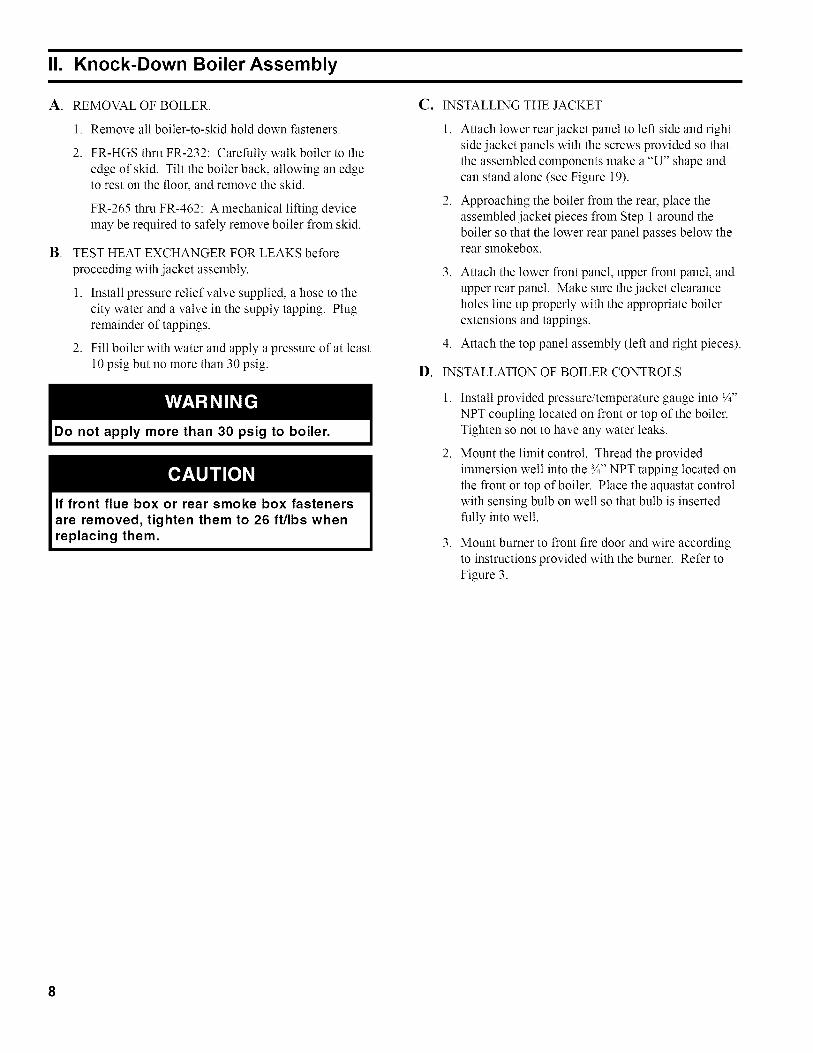
F. CONNECT TANKLESS HEATER PIPING ASSHOWN IN FIGURE 7.
Install automatic mixing valve at tanklessheater outlet to avoid risk of burns or
scalding due to excessively hot water atfixtures. Adjust and maintain the mixing valvein accordance with the manufacturer's
instructions. Do not operate tankless heaterwithout mixing valve.
THE FOLLOWING GUIDELINES SHOULD BEFOLLOWED WHEN PIPING THE TANKLESSHEATER:
1. FLOW REGULATION -- If flow through theheater is greater than its rating, the supply ofadequate hot water may not be able to keep upwith the demand. For this reason a flow regulatormatching the heater rating should be installed inthe cold water line to the heater. The flow regulatorshould preferably be located below the inlet to theheater and a lninilnuln of 3' away from the inletso that the regulator is not subjected to excesstemperatures that may occur during "off' periodswhen it is possible for heat to be conducted backthrough the supply line. The flow regulator alsolimits the flow of supply water regardless of inletpressure variations in the range of 20 to 125 psi.
2. TEMPERING OF HOT WATER -- Installation of
an automatic mixing valve will lengthen the deliveryof the available hot water by mixing some coldwater with the hot. This prevents the possibilityof scalding hot water at the fixtures. In addition,savings of hot water will be achieved since the userwill not waste as much hot water while seeking awater temperature. Higher temperature hot waterrequired by dishwashers and automatic washers ispossible by piping the hot water from the heaterprior to entering the mixing valve. The mixing valveshould be "trapped" by installing it below the coldwater inlet to heater to prevent lime formation in thevalve. Refer to Figure 7.
3. FLUSHING OF HEATER --All water containssome sediment which settles on the inside of the
coil. Consequently, the heater should be periodicallybackwashed. This is accomplished by installinghose bibs as illustrated and allowing water at citypressure to run into hose bib A, through the heater,and out hose bib B until the discharge is clear. Thetees in which the hose bibs are located should bethe same size as heater connections to minimize
pressure drop.
4. HARD WATER -- A water analysis is necessary todetermine the hardness of your potable water. Thisis applicable to some city water and particularly towell water. An appropriate water softener shouldbe installed based on the analysis and dealer'srecommendation. This is not only beneficial to thetankless heater but to piping and fixtures plus themany other benefits derived from soft water.
HOSE BtB
SAFETY RELIEF
GLOBE VALVE
OR SO. HD COCK
COLD WATERSUPPLY
FLOW REGULATOR iNCOLD WATER LiNEAT LEAST 3 FE_
AHEAD OF TANKLESS HEATER
AUTOMATICMIXINGVALVE
HEATER
14
H_GH TEMP WATERFOR AUTOMATICWASHERS, ETC,
Schematic Tankless Heater Piping
®HOSE BiB IN HOT
WATER UNE FOR PERIODIC
FLUSHING OF SEDIME_

IV. Venting
A. GENERAL GUIDELINES
1.
2.
Vent system installation must be in accordancewith these instructions and applicable provisions oflocal building codes. Contact local building or fireofficials about restrictions and installation inspectionin your area.
The FR TM Series is designed to be vented into afireclay tile-lined masonry chimney or chimneyconstructed from type-L vent or a factorybuilt chimney that complies with the type HTrequirements of UL103. The chimney or vent pipeshall have a sufficient draft at all times, to assuresafe proper operation of the boiler. See Figure 8 forrecommended installation.
a.
b.
Install a draft regulator (supplied by installer)following the instructions furnished with theregulator. See Figure 9 for alternate regulatorlocations.
With any new or replacement installation thechimney has to be considered. Chimneys thathave a high heat loss become less suitable asthe heat loss of the home goes down and theefficiency of the boiler goes up. Most homeshave a chimney appropriate for the fuel andthe era in which the home was built. That mayhave been a coal fired or an inefficient oil firedboiler built into a home without insulation or
storm windows. With increasing fuel prices thathome probably has been insulated and fitted withstorm windows so that the heat loss of the home
has been reduced. This requires less fuel to beburned and sends less heat up the chimney.A new boiler probably has a higher efficiencythan the boiler being replaced. That probably
3.
means that the stack temperature from thenew boiler will be lower than that from the
old boiler and with less room air being drawnup the chimney to dilute the stack gases. Thecombination of a large uninsulated chimney,reduced firing rate, reduced firing time, lowerstack temperature and less dilution air can, insome cases, contribute to the condensing of smallamounts of water vapor in the chimney. Suchcondensation, when it occurs, can cause chimneydeterioration. In extreme cases, the chimneymay have to be lined to insulate the chimney andthus prevent the condensation. The addition ofdilution air into the chimney may assist in dryingthe chimney interior surfaces.A massive chimney on a cold, or exposed outsidewall may have produced adequate draft when itwas fired with a higher input and greater volumesof heated gases. With reduced input and volume,the draft may be severely affected. In oneinstance our research showed a new chimney ofadequate sizing produced only -.035" W.C. after
30 minutes of continuous firing at 13.0% CO 2.Outside wall chimneys take longer to heat up andcan have .00" W.C. draft at burner start-up. Youmay have to consider a special alloy chimneyflue liner with insulation around it and stabilizingdraft cap or even a draft inducing fan in severecases.
c. For the same reasons as in (2.) above, heatextractors mounted into the breeching are notreco_mnended.
For minimum clearances to combustible materials
refer to Figure 2.
Figure 8:
,,EF! SIDE VIEW
Recommended Smoke Pipe Arrangement and Chimney Requirements15

PROPER LOCATIONS
ACCRUABLE LOCATION
_LEN
UNACCEPTABLE LOCATIONS
Figure 9: Draft Regulator Locations
V. Electrical
Positively assure all electrical connections are unpowered before attempting installation or serviceof electrical components or connections of the boiler or building. Lock out all electrical boxes withpadlock once power is turned off.
Failure to properly wire electrical connections to the boiler may result in serious physical harm.
Electrical power may be from more than one source. Make sure all power is off beforeattempting any electrical work.
Each boiler must be protected with a properly sized fused disconnect.
Never jump out or make inoperative any safety or operating controls.
The wiring diagrams contained in this manual are for reference purposes only. Refer to thewiring diagram of any controls used with the boiler. Read, understand and follow all wiringinstructions supplied with the controls.
A. GENERAL 3. Wiring should conform to Figures on pages 17 and1. 18 of this manual.
16
2.
Install wiring and electrically ground boiler inaccordance with requirements of the authorityhaving jurisdiction, or in absence of suchrequirements the National Electrical Code, ANSI/NFPA 70, and/or the CSA C22.1 Electric Code.
A separate electrical circuit should be run fromthe main electrical service with a fused disconnectswitch in the circuit.
B. SYSTEM CONTROLS AND WIRING
1. Refer to National Electric Code or Local Electric
Codes for proper size and type of wire required.Follow Code.
2. Use anti-short bushings on all wiring passingthrough boiler jacket, junction boxes and/or controlboxes.
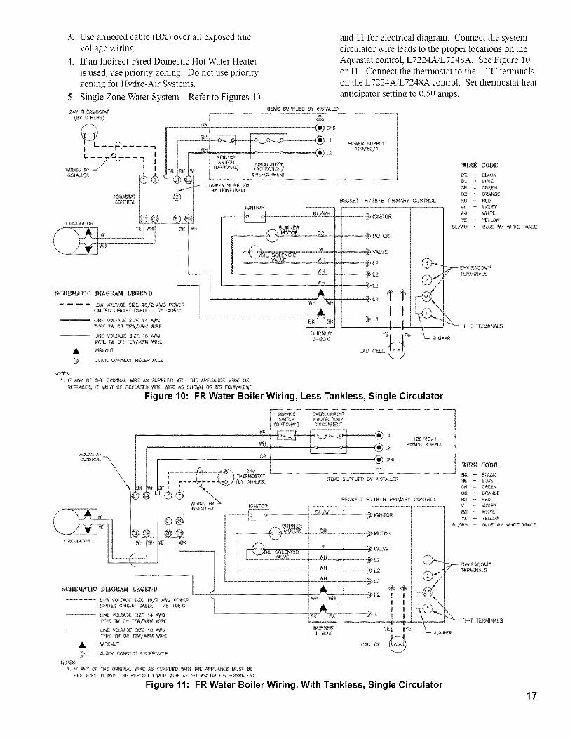
3. Usearmoredcable(BX)overallexposedlinevoltage wiring.
4. If an Indirect-Fired Domestic Hot Water Heater
is used, use priority zoning. Do not use priorityzoning for Hydro-Air Systems.
5. Single Zone Water System - Refer to Figures 10
24V THE PhJO STAT
(_ OTHERS?
SCHEMATIC DIAGRAM LEGEND
.... LOW VOLTAGE $1ZZ 1S/2 AW3 POWER
LJM{YED CIR_JfT C_LS 7B- lOB°
-- _NE VOLYAG£ SIZ£ 14 ANG
WP£ rW OR _WiAW_ W_RE
UN£ VOtfAf;E S_Z_!; I_ A_'#3
TYPE 'PN OR TEW/K¢CM W_R£
A WiR['Nt# f
_ QUCK CONNECT R£C£PTACL£
and 11 for electrical diagram. Connect the systemcirculator wire leads to the proper locations on theAquastat control, L7224A/L7248A. See Figure 10or 11. Connect the thermostat to the 'T-T' terminalson the L7224A/L7248A control. Set thermostat heat
anticipator setting to 0.50 amps.
GR
I_EMS SU_PUED BY _NSTALLER
L1
L2
SWiTC_ D!SCONN_(:T(OPHO_L} PROTOCOl/
C_RCURRE_'41
PO'_R SUPPLY2o/6o/
_ JUMP_ SUPPLieDBY HONEYWELL
WIRE CODE
_ BLA_K
_L - BLUE
GR _ GRER
RO _ R£OB£CKEFf R7184B PRtMARY CON?ROL
YE _ YELLOW
-_ BURNER [ [ Bt:"_ _,U_ W/ _HITE TR#_C:_
MOTOR
I VALVE
, ' L2 @_-.4 _ ENV_RACOM"
CAD CELL _'_)
NOTES:
L F ARY OP
REPLACED_
THE ORIGINAL WR£ _ SUPPLIED WffH TN_ _PL#NC£ _UST _£
_" MUg'[ t3£ R£_L_CED Wm'_ WIRE _ SNO_R OR _TS [QUVAtENL
Figure 10: FR Water Boiler Wiring, Less Tankless, Single Circulator
17

Vl. Oil Piping
A. GENERAL
1. Use flexible oil line(s) so that burner door can
be opened, or burner can be removed, withoutdisconnecting the oil supply.
2. A supply line fuel oil filter is recommended as alninilnuln for all firing rates but a pleated paper fueloil filter is recommended for the lowest firing rateapplications to prevent nozzle fouling.
3. Use Flared fittings only. Do not use compressionfittings.
4. Use of a high efficiency micron filter (Garber orequivalent) in addition to the conventional filter ishighly recommended.
B. SINGLE-PIPE OIL LINES
1. Standard burners are provided with single-stage3450 rpm fuel units with the bypass plug removedfor single-pipe installations.
2. The single-stage fuel unit may be installed single-pipe with gravity feed or lift. Maximum allowablelift is 8 feet. See Figure 14.
AIRVEN
FILLPIPE
OILTANK
FU EL
FLEXIBLE OIL PIPING RECOMMENDEDNEAR BURNER SWING DOOR
PUMP
SHUT-OFFVALVE
IN
MAIN FILTER
RECOMMENDEDFILTER (GARBEROR EQUIVALENT)
MAXIMUMONE PiPE
Figure 14: Single-Pipe Installation
18

TABLE 1:
Lift "H"
(See Figure)
SINGLE STAGE UNITS (3450 RPM)TWO PIPE SYSTEMS
Maximum Length of Tubing"H" +"R" (See Figure)
el
1'
2'
3'
4'
5'
6'
7'
8'
9'
10'
11'
12'
13'
14' ---
3/8" OD
Tubing (3 GPH)
84'
78'
73'
68'
63'
57'
52'
47'
42'
36'
31'
26'
21'
1/2" OD
Tubing (3 GPH)
100'
100'
100'
100'
100'
100'
100'
100'
100'
100'
100'
100'
83'
62'
41'
TABLE 2:
Lift "H"
(See Figure)
TWO-STAGE UNITS (3450 RPM)TWO-PIPE SYSTEMS
Maximum Length of Tubing"H" + "R" (See Figure)
el
2'
4'
6'
8'
10'
12'
14'
16'
18' ---
3/8" OD
Tubing
93'
85'
77'
69'
60'
52'
44'
36'
27'
1/2" OD
Tubing
100'
100'
100'
100'
100'
100'
100'
100'
100'
76'
C. TWO-PIPE OIL LINES
1. For two-piped systems, where more lift is required,the two-stage fuel unit is recommended. Table1 (single-stage) and Table 2 (two-stage) showallowable lift and lengths of 3/8 inch and 1/2 inchOD robing for both suction and return lines. Referto Figure 15.
OUTSIDE TANK FUEL PUMP ABOVE
BOSOM OF TANK
AIRVENT
FLEXIBLENEAR
FUEL PUMP
RETURNLINE
OIL PIPING RECOMMENDEDBURNER SWING DOOR
RECOMMENDEDFILTER (GARBEROR EQUIVALENT)
INLET l
RETUR:NLINE
Figure 15: Two-Pipe Installation19
VII. System Start-Up
EA. VERIFY that the venting, water piping, oil piping,
and electrical system are installed properly. Refer toinstallation instructions contained in this manual.
B. CONFIRM all electrical, water and oil supplies areturned off at the source and that the vent is clear fromobstructions.
Completely read, understand and follow allinstructions in this manual before attemptingstart up.
C. FILL ENTIRE HEAT1NG SYSTEM WITH WATER
O.
2O
F.
G°
CHECK CONTROLS, WIRING AND BURNER
to be sure that all connections are tight and burner isrigid. Verify that all electrical connections have beencompleted, fuses installed, that the oil tank is filled andoil lines have been tested.
LUBRICATION. Follow instruction on burner and
circulator label to lubricate, ifoil lubricated. Most
motors currently used on residential type burnersemploy permanently lubricated bearings and thus donot require any field lubrication. Water lubricatedcirculators do not need field lubrication.
ADJUST CONTROL SETTINGS with burnerservice switch turned "ON" and room thermostat set
and vent air from system.steps below:
1.
See Figures 5 & 6 and follow
Close isolation valve in boiler supply piping.
2. Isolate all circuits by closing zone valves orbalancing valves.
3. Attach a hose to hose bib located just beforeisolation valve in boiler supply piping. See Figures5 and 6. (Note - Terminate hose at a suitable floordrain or outdoor area).
4. Starting with one circuit at a time, open zone valveor valve.
5. Open hose bib.
6. Open fill valve (Make-up water line should belocated directly after isolation valve in boiler supplypiping between air scoop and expansion tank).
7. Allow water to flow into drain until discharge fromhose is bubble free for 30 seconds.
8. When zone is completely purged of air, close zonevalve or balancing valve. Open the zone valve forthe next zone to be purged. Repeat this step untilall zones have been purged. At completion, open allzone valves or valves.
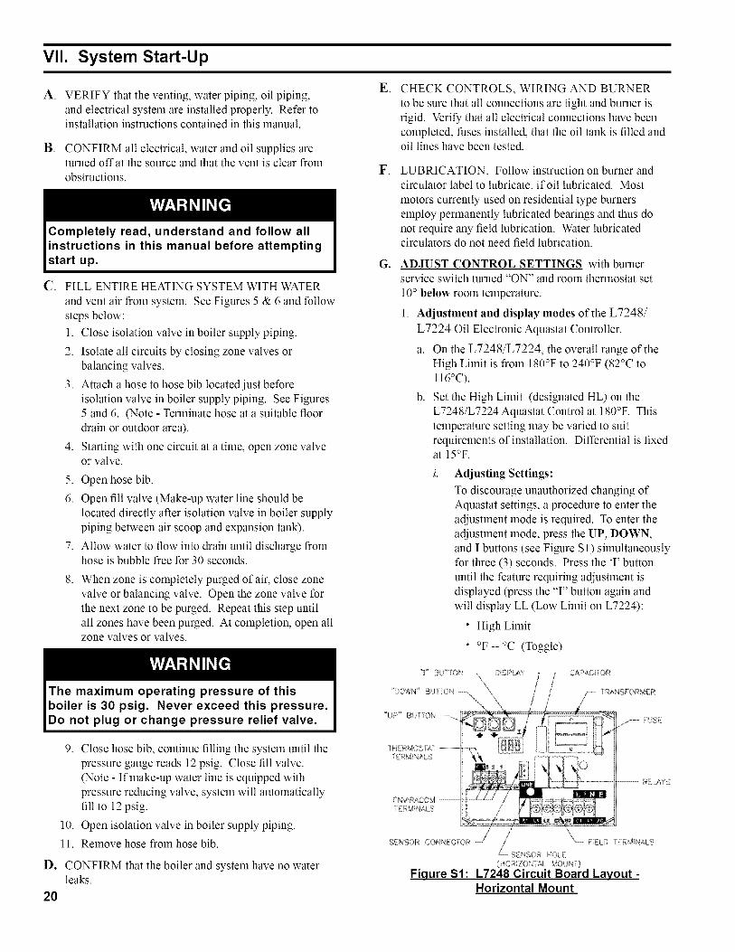
10° below room temperature.
1. Adjustment and display modes of the L7248/
L7224 Oil Electronic Aquastat Controller.
a. On the L7248/L7224, the overall range of theHigh Limit is from 180°F to 240°F (82°C to116°C).
b. Set the High Limit (designated HL) on theL7248/L7224 Aquastat Control at 180°F. Thistemperature setting may be varied to suitrequirements of installation. Differential is fixedat 15°F.
Adjusting Settings:
To discourage unauthorized changing ofAquastat settings, a procedure to enter theadjustment mode is required. To enter theadjustment mode, press the UP, DOWN,and I buttons (see Figure S1) simultaneouslyfor three (3) seconds. Press the T button
until the feature requiring adjustment isdisplayed (press the 'T' button again andwill display LL (Low Limit on L7224):
• High Limit
• °F -- °C (Toggle)
The maximum operating pressure of thisboiler is 30 psig. Never exceed this pressure.Do not plug or change pressure relief valve.
9. Close hose bib, continue filling the system until thepressure gauge reads 12 psig. Close fill valve.(Note - If make-up water line is equipped withpressure reducing valve, system will automaticallyfill to 12 psig.
10. Open isolation valve in boiler supply piping.
11. Remove hose from hose bib.
CONFIRM that the boiler and system have no waterleaks.
RELAYS
>NSORCON,_CrO
Fiqure S1 :
f°ELD _ERMNALS
SENSOR _{OLE(HOPJZON_AL MOUN1)
L7248 Circuit Board Lagout -Horizontal Mount
Textbt
HL
I_/_
fC
LL
ii.
Then press the UP and/or DOWN buttons
to move the set point to the desired value.
After 60 seconds without any button inputs,
the control will automatically return to theREAD mode.
Display:
In the RUN mode, the Aquastat willflash "bt" (boiler temp.) followed by thetelnperamre (i.e., 220), followed by °F or°C.
To read boiler settings, press the T key toread the parameter of interest. For example,press I (HL) High Limit is displayed,followed by a three-digit number, i.e., 220,followed by °F or °C.
See Figure $2 for Display ReadoutDefinitions.
DisplayDescription ShowsBoiler Temperature b
High Limit H LError Code E r r
Degrees Fahrenheit D
Degrees Celsius o [
Low Limit L [
Fiqure S2: Display Readout Definitions
After approximately 60 seconds withoutany key pressed, the display will enter adim display mode. To return to the brightdisplay mode, simply press any key.
2. Control Operating Characteristics
The L7248/L7224 can be in any three (3)operational states: Normal, High-Limit and Error.The controller moves back and forth from High-Limit to Normal state as part of normal operation.
The controller will enter the Error state when there
is an abnormal condition. The operating states are:
a. Normal: Boiler temperature has gone below thehigh limit setting (minus the differential) and hasnot exceeded the high limit setting.
b. High-Limit: Boiler temperature has gone abovethe high limit setting and has not dropped belowthe high limit setting (minus the differential).
c. Error: The controller has detected an error
condition (e.g., open sensor) and has shut downthe burner output. The controller continues tomonitor the system and automatically restarts ifthe error condition clears. See Table S1.
d. Low-Limit: Boiler temperature has gonebelow the low limit setting (minus the low limitdifferential) and has not gone above the low limitsetting.
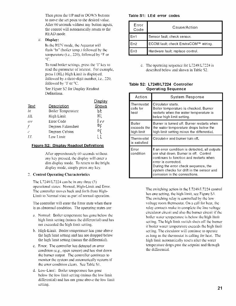
Table Sl :
ErrorCode
Err1
Err2
Err3
LEd error codes
Cause/Action
Sensor fault; check sensor.
ECOM fault; check EnviraCOM TM wiring.
Hardware fault; replace control.
e. The operating sequence for L7248/L7224 isdescribed below and shown in Table $2.
Table S2:L7248/L7224 ControllerOperating Sequence
Action System Response
Thermostat Circulator starts.
calls for Boiler temperature is checked. Burnerheat restarts when the water temperature is
below high limit setting.
Boiler Burner is turned off. Burner restarts when
exceeds the the water temperature drops below thehigh limit high limit setting minus the differential.
Thermostat Circulator and burner turn off.is satisfied
Errorcondition
If an error condition is detected, all outputsare shut down. Burner is off. Controlcontinues to function and restarts whenerror is corrected.
During the error check sequence, thesystem checks for drift in the sensor andcorrosion in the connections.
The switching action in the L7248/L7224 controlhas one setting, the high limit, see Figure $3.The switching relay is controlled by the lowvoltage room thermostat. On a call for heat, therelay contacts make to complete the line voltagecirculator circuit and also the burner circuit if the
boiler water temperature is below the high limitsetting. The high limit switch shuts off the burnerif boiler water temperature exceeds the high limitsetting. The circulator will continue to operateas long as the thermostat is calling for heat. Thehigh limit automatically resets after the watertemperature drops past the setpoint and throughthe differential.
21

240_i :: {i _v ¸'_
i-_{. _ ijM:/i̧S_NiiI'4:¸@_ i......................................_...........
ii_ _ _w<',,!
OP::bq ::1
:L A F(:4 ::1/::
: 'i :41!K::::
: /,,
H. REMOVE GUN ASSEMBLY
W ' _@ KA( N(,
:@IVAN}, SW C: r'R!A,{S
{' RS ,is
SWi C :iA_,_ :0 ON
%:: ;!< ]'} ©:. :0VA% AN !/N_,"M
WS::R _ t_sERAr i%:
p,
C:::: (P %1:: :: V:" :::'q:_? :_,,_::: ......: :....... :::0[!
Fiqure S3:LT248/L7224 Setpoint and DifferentialSwitchinq Action
Check nozzle size, head size, gun setting, andpositioning of electrodes. This information is shownin Figures 16 & 17 and Table 3.
2. Reinstall gun assembly.
Beckett AFG & SF BurnersTable 3:
BoilerModel
FR-HGS*
FR-HGS
FR-HGSII
FR-98*
FR-122
FR-147
FR-173
FR-205
FR-232
FR-265
FR-305
FR-350
FR-400
FR-462
I. VERIFY OIL BURNER SETTINGS BEFORE
STARTING
1. BURNER AIR BAND AND AIR SHUTTER
SETTINGS, see Table 3.
2. OPEN ALL OIL LINE VALVES.
3. Attach a plastic hose to fuel pump vent fitting andprovide a container to catch the oil.
REMOVE GAUGE PORT PLUG from fuel pump4.
and install pressure gauge.
FiringRate
(GPH)
o.8o
1 .oo
1.30
o.85
1 .lO
1.25
1.50
1.75
2.oo
2.5o
2.75
3.oo
3.5o
4.00
Nozzle
.65 X 60WDelavan
.85 X 60BHago
1.10 X 60WDelavan
.75 X 60B
Hago
.90 X 60B
Hago
1.00 X 60B
Hago
1.25 X 60B
Hago
1.50 X 60B
Hago
1.65 X 60B
Hago
2.50 X 80BDelavan
2.75 X 80BDelavan
3.00 X 80BDelavan
3.50 X 80BDelavan
4.00 X 80BDelavan
BurnerModel
AFG
SF
Head
L-1
V-1
V-1
V-1
F-220
F-300
t_o
StaticPlate
3-3/8"U
START OIL BURNER
1. Open vent fitting on fuel pump.
Settings
Head
Bearing
0
0
0
0
2
3
4
*Equipped with low firing rate baffle
2-3/4"U
Air
Shutter Band
10 0
9 1
9 2
10 0
9 0
10 0
5 3
10 3
4 4
5 0
5 2
5 3
5 3
5 2
22
PumpPressure
140 PSI
140 PSI
140 PSI
140 PSI
140 PSI
140 PSI
140 PSI
140 PSI
140 PSI
100 PSI
100 PSI
100 PSI
100 PSI
100 PSI

/
ELECTRODE ADJUSTMENT"LI" OR "Vl" HEAD
NOZZLE
L1 HEAD
LOCATON OF HEAD AT "0" POSITIONON ADJUSTING PLATE
"V!" VARIABLE HEAD
W!TNESS MARK
PRIMARY ADJUSTINGPLATE
KNURLED NUT
SECONDARY ADJUST NG/ PLATE
ACORNLOCK WASHER
1_ ±_
)
HEAD SETTING (AT "0")"Vi" HEAD
V! HEAD
Figure 16: "LI"& "VI" Head Electrode Positioning and Gun Setting (Beckett AFG)¢0

, /t6 /
ELECTRODE ADJUSTMENTS
..... -J
JFigure 17: Electrode / Head Setting ("F" Head)
Ko
Lo
24
2. TURN 'ON' BURNER service switch andallow burner to run until oil flows from vent
fitting in a SOLID stream without air bubbles forapproximately 10 seconds.
3. Close vent fitting and burner flame should startimmediately.
4. If the burner does not start immediately, checkthe manual overload switch on the motor, if so
equipped, and the safety switch on the burnerprimary control.
ADJUST OIL PRESSURE
1. Locate oil pressure adjusting screw and turn screwuntil Pressure Gauge reads the correct pumppressure required for the specific boiler. Refer toTable 3.
2. DO NOT REMOVE PRESSURE GAUGE untillater.
OTHER ADJUSTMENTS
1. ADJUST THE AIR BAND AND/OR AIRSHUTTER.
2.
3.
a. Adjust air supply by loosening lock screws andmoving the air shutter and if necessary the airband. Refer to Table 3 preliminary settings.
ADJUST DRAFT REGULATOR for a draft of
-.02" (water gauge) over the fire after chimney hasreached operating temperature and while burner isrunning.
READJUST AIR BANDS on burner for a lightorange colored flame while draft over the fire is-.02" w.c. Use a smoke test and adjust air forminilnuln smoke (not to exceed #1) with a lninilnulnof excess air. Make final check using suitable
instrumentation to obtain a CO2of 11.5 to 12.5%with draft of-.02" w.c. in fire box. These settingswill assure a safe and efficient operating condition.If the flame appears stringy instead of a solid flame,try another nozzle of the same type. Flame should
4.
be solid and compact. After all adjustlnents havebeen made, recheck for a draft of-.02" w.c. over thefire.
TURN "OFF" BURNER and remove pressuregauge. Install gauge port plug and tighten. Startburner again.
M. FLAME FAILURE
The FR boiler controls operate the burner automatically.If for unknown reasons the burner ceases to fire and
the reset button on the primary control has tripped, theburner has experienced ignition failure. Before pressingthe reset button, call your serviceman immediately.
Do not attempt to start the burner whenexcess oil has accumulated, when the unit isfull of vapor, or when the combustionchamber is very hot.
No CHECK FOR CLEAN CUT OFF OF BURNER
1. AIR IN THE OIL LINE between fuel unit and
nozzle will compress when burner is on and willexpand when burner stops, causing oil to squirt fromnozzle at low pressure as burner slows down andcausing nozzle to drip after burner stops. Usuallycycling the burner operation about 5 to 10 times willrid oil line of this air.
2. IF NOZZLE CONTINUES TO DRIP, repeat stepN. 1. If this does not stop the dripping, remove cutoffvalve and seat, and wipe both with a clean clothuntil clean. Then replace and readjust oil pressure.If dripping or after burn persist replace fuel pump.
0. HINTS ON COMBUSTION
NOZZLES--Although the nozzle is a relativelyinexpensive device, its function is critical to thesuccessful operation of the oil burner. The selectionof the nozzle supplied with the FR boiler is the

[o)iii[o.)=
2.
result of extensive testing to obtain the best flameshape and efficient combustion. Other brands ofthe same spray angle and spray pattern may beused but may not perform at the expected level of
CO 2 and smoke. Nozzles are delicate and shouldbe protected from dirt and abuse. Nozzles are massproduced and can vary from sample to sample. Forall of those reasons a spare nozzle is a desirable itemfor a serviceman to carry.
FLAME SHAPE -- Looking into the combustionchamber through the flame plug hole, the flameshould appear straight with no sparklers rolling uptoward the top of the chamber. If the flame drags tothe right or left, sends sparklers upward or makeswet spots on the combustion chamber, the nozzleshould be replaced. If the condition persists lookfor fuel leaks, air leaks, water or dirt in the fuel asdescribed below.
3. FUEL LEAKS-- Any fuel leak between thepump and the nozzle will be detrimental to goodcombustion results. Look for wet surfaces in the air
tube, under the ignitor, and around the air inlet. Anysuch leaks should be repaired as they may causeerratic burning of the fuel and in the extreme casemay become a fire hazard.
4. AIR LEAKS-- Any such leaks should be repaired,as they may cause erratic burning of the fuel and inextreme cases may become a fire hazard.
There may be many possible causes of leaks in oil linessuch as:
a. Fitting leaks due to misflared tubing or damagedfitting.
b. Fuel line leak due to crushed or bent tubing.
c. Filter connection leaks.
d. Tank connection leaks.
The following actions can eliminate air leaks:
a. Bleed pump as detailed in System Start-UpSection of this manual.
b. Replace flare fittings.
c. Replace oil supply line.
d. Repair oil filter leaks
e. Replace or repair tank fittings.
5. GASKET LEAKS-- If 11.5% to 12.5% CO 2 witha #1 smoke cannot be obtained in stack, look for air
leaks around the canopy seal. Such air leaks will
cause a lower CO2 reading in the stack. The smallerthe firing rate the greater effect an air leak can have
on CO 2readings.
6. DIRT-- A fuel filter is a good investment.Accidental accumulation of dirt in the fuel systemcan clog the nozzle strainer and produce a poorspray pattern from the nozzle.
CHECK TEST PROCEDURE. A very goodtest for isolating fuel side problems is todisconnect the fuel system and with a two(2) foot length of tubing, fire out of anauxiliary five gallon pail of clean, fresh,warm #2 oil from another source. If theburner runs successfully when drawing outof the auxiliary pail then the problem isisolated to the fuel or fuel lines being usedon the jobsite.
7.
8.
WATER-- Water in the fuel, in large amounts,will stall the fuel pump. Water in the fuel pump, insmaller amounts, will cause excessive wear on thepump, but more importantly water does not burn. Itchills the flame, causes smoke, and allows unburnedfuel to pass through the combustion chamber andclog the flueways of the boiler.
COLD OIL--If the oil temperature approachingthe fuel pump is 40°F or lower, poor combustionor delayed ignition may result. Cold oil is harderto atomize at the nozzle. Thus, the spray dropletsget larger and the flame shape gets longer. Anoutside fuel tank that is above grade or has fuel linesburied in the ground above the frost line is a goodcandidate for cold oil. The best solution is to placethe tank and oil lines in the ground below the frostline.
9. HIGH ALTITUDE INSTALLATIONS
Typically, the rule to use for high altitudes is toincrease the air supply by 4% per each 1000 ft.above 2000 ft. altitude from sea level. This means
that the air setting will have to be higher than thecalibration marks in proportion to the altitude. Use
instruments and set for 11.5 to 12.5% CO2.
10. START-UP NOISE -- Late ignition is the cause ofstart-up noises. If it occurs recheck for electrodesettings, flame shape, air or water in the fuel lines.
11. SHUT DOWN NOISE -- If the flame runs out of
air before it runs out of fuel, an after burn withnoise may occur. That may be the result of a faultycut-off valve in the fuel pump, or it may be airtrapped in the nozzle line. It may take several firing
cycles for that air to be fully vented through thenozzle. Water in the fuel or poor flame shape canalso cause shut down noises.
25

P. TEST CONTROLS
Before installation of the boiler is
considered complete, the operation of theboiler controls should be checked,particularly the primary control and highlimit control.
1. CHECK THERMOSTAT OPERATION. Raise
and lower thermostat setting as required to start andstop burner.
2. VERIFY PRIMARY CONTROL SAFETY
FEATURES using procedures outlined inInstructions furnished with control (See back ofControl Cover) or Instructions as follows:
26
Service on of this boiler should beundertaken only by trained and skilledpersonnel from a qualified service agency.
a. Simulate flame failure:
• Follow the starting procedure to turn on theburner.
Close the hand valve in the oil supply line.
Control enters recycle mode and triesto restart burner after approximately 60seconds.
Safety switch should lock out inapproximately 15 seconds. Ignition andmotor should stop.
Indicator light will flash 1/2second on,1/2second off.
b.
• Push red reset button to reset safety switch.
Simulate ignition failure:
• Follow the starting procedure to turn on theburner, but do not open the oil supply handvalve.
• Safety switch should lock out inapproximately 15 seconds. Ignition andmotor should stop.
• Indicator light will flash 1/2second on,
1/2second off.
C.
• Push red reset button to reset safety switch.
Simulate power failure:
Follow the starting procedure to turn on theburner.
With the burner running, turn off the powerto the system by tripping the circuit breakeror removing the fuse.
• Burner should stop.
• Restore power. Burner should start.
3. VERIFY HIGH LIMIT OPERATION.
a. Adjust thermostat to highest setting.
b. Observe temperature gauge. When temperatureis indicated, adjust limit to setting belowobserved temperature. Burner should stop.
c. Adjust limit to setting above observedtemperature. Burner should start.
d. Adjust thermostat to lowest setting. Adjust limitto desired setting.
CHECK LOW WATER CUTOFF (if soequipped).
a. Adjust thermostat to highest setting.
b. With boiler operating, open drain valve andslowly drain boiler.
c. Burner should stop when water level dropsbelow low water cutoffprobe. Verify limit,thermostat or other controls have not shut offboiler.
4.
d. Adjust thermostat to lowest setting. Refill boiler.
Q. BOILER IS NOW READY TO BE PUT INTOSERVICE.
IF, DURING NORMAL OPERATION, IT ISNECESSARY TO ADD WATER MOREFREQUENTLY THAN ONCE A MONTH,CONSULT A QUALIFIED SERVICETECHNICIAN TO CHECK YOUR SYSTEM FORLEAKS.
A leaky system will increase the volume of make-upwater supplied to the boiler which can significantlyshorten the life of the boiler. Entrained in make-upwater are dissolved minerals and oxygen. When thefresh, cool make-up water is heated in the boiler theminerals fall out as sediment and the oxygen escapesas a gas. Both can result in reduced boiler life. Theaccumulation of sediment can eventually isolate thewater from contacting the steel. When this happensthe steel in that area gets extremely hot and eventuallycracks. The presence of free oxygen in the boiler createsa corrosive atmosphere which, if the concentrationbecomes high enough, can corrode the steel throughfrom the inside. Since neither of these failure types arethe result of a manufacturing defect the warranty doesnot apply. Clearly it is in everyone's best interest toprevent this type of failure. The maintenance of systemintegrity is the best method to achieve this.

VIII. Service and Cleaning
1. CLEAN THE FIRETUBES
A.
B.
BURNER SHUTDOWN:Switch to turn off burner.
Open Service
Manual Oil Supply Valve should beclosed and Electric Service to boiler
turned off if boiler will not be operatedfor an extended period of time.
GENERAL
Inspection service and cleaning should be conducted
annually. Turn off electric power and close oil supply
valve while conducting service or maintenance.
FIRETUBES AND COMBUSTION CHAMBER
(See Figure 18)
a. Disconnect electric service to burner.
b. To gain access to the firembes, remove the frontflue box door. For boilers equipped with fluebox swingdoor, remove two (2) nuts at top offlue box door and swing door down. For boilersnot equipped with swingdoor, remove fastenersaround the perimeter of flue box frame andremove door.
c. Remove turbulators.
d. Using a firetube brush clean firetubes. Use carenot to damage the insulation on the inside of theflue box.
e. Replace mrbulators and flue box door.
Units should be cleaned at least once a year, preferablyat the end of each heating season.
It is not necessary to remove burner to clean boiler.
Figure 18: Cleaning of FR Boiler27

Warninu:
This product contains refractory ceramic fibers (RCF). RCF has been classi-
fied as a possible human carcinogen. After this product is fired, RCF may, when
exposed to extremely high temperature (> 1800F), change into a known human
carcinogen. When disturbed as a result of servicing or repair, RCF becomes
airborne and, if inhaled, may be hazardous to your health.
AVOID Breathing Fiber Particulates and Dust
Precautionary Measures:
Do not remove or replace previously fired RCF (combustion chamber insulation,
target walls, canopy gasket, flue cover gasket, etc.) or attempt any service or
repair work involving RCF without wearing the following protective gear:
1. A National Institute for Occupational Safety and Health (NIOSH) ap-
proved respirator
2. Long sleeved, loose fitting clothing
3. Gloves
4. Eye Protection
• Take steps to assure adequate ventilation.
• Wash all exposed body areas gently with soap and water after contact.
• Wash work clothes separately from other laundry and rinse washing ma-
chine after use to avoid contaminating other clothes.
• Discard used RCF components by sealing in an air tight plastic bag.
First Aid Procedures:
• If contact with eyes: Flush with water for at least 15 minutes. Seek
immediate medical attention if irritation persists.
• If contact with skin: Wash affected area gently with soap and water.
Seek immediate medical attention if irritation persists.
• If breathing difficulty develops: Leave the area and move to a loca-tion with clean fresh air. Seek immediate medical attention if breath-
ing difficulties persist.
• Ingestion: Do not induce vomiting. Drink plenty of water. Seek im-mediate medical attention.
28

IX. Repair Parts
All FR TM Repair Parts may be obtained through your local New Yorker Wholesale distribu-
tor. Should you require assistance in locating a New Yorker distributor in your area, or have
questions regarding the availability of New Yorker products or repair parts, please contact New
Yorker Boiler Co., Inc. Customer Service at (215) 855-8055 or Fax (215) 855-8229.
29

Figure 19: Jacket Repair Parts
30

JACKET ASSEMBLY
ITEM DESCRIPTION
Jacket Top Left Panel
Jacket Top Right Panel
Jacket Upper Front Panel
(2) Jacket Lower Left/Right FrontPanels & (1) Lower Front Tie Bar
Jacket Lower Front Panel
Jacket Right Side Panel
Jacket Left Side Panel
Jacket Lower Rear Panel
Jacket Upper Rear Panel
FR-HGS
FR-HGSII
FR-98/122
FR-147/173
FR-205/232/265/305
FR-350/400
FR-462
FR-HGS
FR-HGSII
FR-98/122
FR-147/173
FR-205/232/265/305
FR-350/400
FR-462
FR-98/122
FR-147 thru 305
F R-350/400/462
FR-HGS/HGSII
FR-98/122
FR-147/173
FR-205/232
FR-265/305
FR-350/400/462
FR-HGS/HGSII
FR-98/122
FR-147/173
FR-205/232
FR-265/305
FR-350/400
FR-462
FR-HGS/HGSII
FR-98/122
FR-147/173
FR-205/232
FR-265/305
FR-350/400
FR-462
FR-HGS/HGSII
FR-98/122
FR-147 thru FR-305
FR-350/400/462
FR-98/122
FR-147 thru FR-232
FR-265/305
FR-350/400/462
PART NUMBER
60472010
60472011
60472012
60472013
60472014
60472015
60472016
604370372
60472020
60437037
60437046
60437054
60437067
60437071
60437034
60437043
60437060
L/RPanels
[2] 60437039
[2] 60437047
9 ASME Data Cover Plate FR-147 thru FR-462
Notes:
1. Jacket Lower front panels on FR boilers equipped with burner swingdoor are constructed of three individual pieces.
60472040
60472041
604370312
60437031
60437040
60437055
60437057
60437064
60437068
604370322
60437032
60437041
60437056
60437058
60437065
60437069
60437033
60437042
60437063
60437035
60437044
60437059
60437062
60472050
We Bar
60472030
60472031
2. Jacket sets for special builds may have unique panels not listed here. For special build parts contact New Yorker Boiler Co., Inc. Customer Service.
31

/
Figure 20: FR Bare Boiler Repair Parts
Z©
-<
©
u)
o.
>©
©

BARE BOILER ASSEMBLY
ITEM DESCRIPTION
N/A
Front Flue Box Assembly(See next page for Insulation Kits)
Front Fluebox Door Insulation
(See next page for Insulation Kits)
2 Flanged Hex Nut, 3/8-16
Burner Door Assembly
Burner Door Insulation
(See next page for Insulation Kits)
Floor Insulation
(See next page for Insulation Kits)
Rear Smokebox
FR-HGS/98/122
FR-HGSll
FR-147/173/205/232
FR-265/305
FR-350/400/462
FR-HGS/98/122
FR-HGSll
FR-147/173/205/232
FR-265/305
FR-350/400/462
All Models
FR-HGS/HGSll
FR-98/122
FR-147/173/205/232
FR-265/305
FR-350/400/462
FR-HGS/HGSll
FR-98/122
FR-147 thru FR-305
FR-350/400/462
FR-HGS/HGSll
FR-98/122
FR-147/173
FR-205/232/265/305
FR-350/400
FR-462
FR-HGS/98/122
FR-HGSll
FR-147/173
FR-205/232
FR-265/305
FR-350/400/462
All Models (Except FR-265/305)
FR-265/305
All Models
Braided Fiberglass Rope Gasket, 3/16"7
Braided Fiberglass Rope Gasket, 3/8"
8 Braided Fiberglass Rope Gasket, 3/16"
9 Boiler Shell Assembly Contact Sales Office
10 Observation Door
11 Heater Coil/Cover Plate Gasket
12 Blank Heater Cover Plate
13 Tankless Heater Coil
14 Hex Head Cap Screw, 3/8-16 x 1-1/4 LG
15 Hea W Hex Nut, 3/8-16
16 Sheet Metal Screw, #12 x 3/4 LG
17 Hex Head Cap Screw, 3/8-16 x 3/4 LG
18 Cerafelt Insulation, 1/2" x 1"
All Models
All Models
All Less Heater Models
S-4
S-5
S-6
FR-147/173
FR-147 thru FR-462
FR-147 thru FR-462
FR-147 thru FR-462
All Sizes
PART NUMBER
61172001
61172002
61172003
61172004
61172005
82072008
82072009
82072010
82072011
82072012
80860498
6257201
6257202
6257206
6257207
82072013
82072014
82072015
82072016
82072017
82072018
82072019
82072020
61137004
61137003
61137005
61137006
61137007
61137008
82072025
82072024
82072026
8023701
8206036
7033715
6037201
6037202
C08700
80861360
80860400
80860041
808601375
9206005 (Specify Length)
Notes:1. Bare boiler parts for special builds may be different than those listed here. Contact New Yorker Boiler Co., Inc. Customer Service for special
build boiler parts.
33

INSULATION REPLACEMENT KITS
Combustion Chamber Insulation Replacement Kits
Combustion Chamber Insulation Replacement Kits provide the floor insulation and the burner door insulation.
FR Model(s) Kit Part Number
FR-HGS/HGSII/98/122 62072001
FR-147/173 62072002
FR-205/232/265/305 62072003
FR-350/400 62072004
FR-462 62072005
Flue Box Insulation Replacement Kits
Flue Box Insulation Replacement Kits provide the flue box door insulation, flue box frame top/bottom insulationpieces and flue box frame side insulation pieces.
FR Model(s) Kit Part Number
FR-HGS/98/122 62072006
FR-HGSll 62072007
FR-147/173/205/232 62072008
FR-265/305 62072009
FR-350/400/462 62072010
34

BECKETT BURNER PARTS LIST FOR FR SERIES STEEL BOILERS
FOR REPLACEMENT OIL BURNER PARTS, CONTACT YOUR WHOLESALER OR THE BURNER MANUFACTURER:
R. W. BECKETT CORE
R O. BOX 1289
ELYRIA, OHIO 44036
1-800-645-2876
NOTE: When ordering parts always give the serial and model numbers shown on the boiler and burner. Also, provide thename of the part(s).
Ordering Information for Quality Replacement Parts
SIDE VIEWFRONT VIEW
Figure 21: BECKETT AFG MODEL BURNER
35

BECKETT BURNER PARTS LIST FOR FR SERIES STEEL BOILERS
FOR REPLACEMENT OIL BURNER PARTS, CONTACT YOUR WHOLESALER OR THE BURNER MANUFACTURER:
R. W. BECKETT CORR
R O. BOX 1289
ELYRIA, OHIO 440361-800-645-2876
\
®
36
1
2
6
7
8
9
lO
11
12
15
16
18
Figure 22:
Air Band
Air Shutter
Blower
Bulkhead Fitting
Bulkhead Fitting Locknut
Connector Tube Assembly
Coupling
Electrode Clamp
Electrode Insulator Assembly
Spider Spacer Assembly
Escutcheon Plate
Flange and Air Tube Assembly
BECKETT AF and SF MODEL BURNERS
19 Head
20 Housing Assembly w/Inlet Bell
21 Motor
22 Nozzle Adapter
23 Nozzle Line Electrode Assembly
25 Pump
27 Static Plate
28 Ignitor
29 Ignitor Hinge Screw
30 Ignitor Holding Screw
31 Ignitor Gasket Kit
32 Wire Guard

X. Low Water Cut Off (LWCO)
DO NOT ATTEMPT to cut factory wires to install an aftermarket Low Water Cut Off (LWCO).Only use connections specifically identified for Low Water Cut Off.
In all cases, follow the Low Water Cut Off (LWCO) manufacturer's instructions.
When
A low water cutoff is required to protect a hot waterboiler when any connected heat distributor (radiation)is installed below the top of the hot water boiler (i.e.baseboard on the same floor level as the boiler). Inaddition, some jurisdictions require the use of a LWCOwith a hot water boiler.
Where
The universal location for a LWCO on both gas and oilhot water boilers is above the boiler, in either the supplyor return piping. The lninilnuln safe water level of awater boiler is at the uppermost top of the boiler; that is,it must be full of water to operate safely.
What Kind
Typically, in residential applications, a probe typeLWCO is used instead of a float type, due to theirrelative costs and the simplicity of piping for a probeLWCO.
manufacturers reco_ranend an annual inspection of theprobe.
How to Wire
LWCO's are available in either 120 VAC or 24 VAC
configurations. The 120 VAC configuration can beuniversally applied to both gas and oil boilers by wiringit in the line voltage service to the boiler (after theservice switch, if so equipped).The presence of water in a properly installed LWCOwill cause the normally open contact of the LWCO toclose, thus providing continuity of the 120 VAC serviceto the boiler.
It is recommended to supply power to the probe LWCOwith the same line voltage boiler service as shownbelow.
_E OLTAOE
N 31,18
How to Pipe
A "tee" is co_ranonly used to connect the probe LWCOto the supply or return piping, as shown below.
SYSiN_
SYSI_,_ Si,i P Y
_E_U;RN I;'I:K O_d_/)
1_411%_UM E_@A//El LiNE
LWCO Location
Select the appropriate size tee using the LWCOmanufacturer's instructions. Often, the branch
connection must have a minimum diameter to
prevent bridging between the probe and the tee. Also,the run of the tee must have a lninilnuln diameter to
prevent the end of the probe from touching or beinglocated too close to the inside wall of the run of the tee.
Ideally, manual shutoff valves should be locatedabove the LWCO and the boiler to allow for servicing.This will allow probe removal for inspection withoutdraining the heating system. Many probe LWCO
!
oP o_,,', i [ ............................i___4L...!I:i ,.*,,= i _ I ................i } IT +
_,,/?, NA]E< * * .Lt ......
c;.=: i/ ' ,,_:N_?i i i_VS:: _: TO L¢Ol
4/ ,
_US'PLC"0,:,) iN {H©
0 0 ItOa_
Wiring ol Typical LW¢O
A 24 VAC LWCO is used primarily for gas firedboilers where a 24 volt control circuit exists within the
boiler. However, a 24 VAC LWCO can only be usedif the boiler manufacturer has provided piping andwiring connections and instructions to allow for thisapplication.
How to Test
Shut off fuel supply. Lower water level until waterlevel is BELOW the LWCO. Generate a boiler demand
by turning up thermostat. Boiler should not attempt tooperate. Increase the water level by filling the system.The boiler should attempt to operate once the waterlevel is above the LWCO.
37

DATE
SERVICE RECORDSERVICE PERFORMED
38

DATE
SERVICE RECORDSERVICE PERFORMED
39

NEW YORKER BOILER CO., INC.
.imitei i arrantie For Residential Cast Iron and Steel Water Boilers
By this Warranty Statement New Yorker Boiler Co., Inc. ("New Yorker"),issues limited warranties subject to the terms and conditions stated below.
These limited wan'anties apply to residential cast iron and steel water boilers
labeled with the New Yorker (R)brand which are sold on or after March 1,
2004.ONE YEAR LIMITED WARRANTY
One Year Limited Wan'anty for Residential Water Boilers New Yorker
warrants to the original consumer purchaser at the original installation addressthat its residential cast iron and steel water boilers will be fi'ee fi'om defects in
material and workmanship nnder normal usage for a period of one year from
the date of original installation. In the event that any defect in material or
worMnanship is fonnd during the one year period lbllowing the date of
installation, New Yorker will, at its option, repair the detective part or providea replacement fi'ee of charge, F.O.B. its facto_ T.
FIVE YEAR LIMITED WARRANTY
Five Year Pressure Vessel Limited Wan'ant,/for WC TM Residential Water
Boilers New Yorker warrants to the original consumer purchaser at the
original installation ad&ess that the pressure vessel of the boiler will be fi'eeof defects in material and worMnanship under normal usage lbr a period of
five years following the date of installation. In the event that any defect in
material or workmanship is fonnd during the five year period lbllowing the
date of installation, New Yorker will, at its option, repair the defectivepressure vessel or provide a replacement flee of charge, F.O.B. its I:actol T.
LIFETIME LIMITED WARRANTY
Lifetime Pressure Vessel Limited Walxanty lbr AP-U TM. FR TM S-AP TM.
microTEK3T'_L microTEKDV TM. CLW TM. CG-A TM. and PVCG TM Residential
Water Boilers New Yorker warrants to the original consnmer purchaser at the
original installation ad&ess that the pressure vessel component of the boiler
will be flee of defects in material and worMnanship under normal usage forthe lifetime of the original consnmer purchaser. In the event that any defect in
material or workmanship is fonnd during the ten year period following the
date of installation, New Yorker will, at its option, repair the defective
pressnre vessel or provide a replacement flee of charge, F.O.B. its I:actol T. Inthe event that any defect in material or workmanship is found after the tenth
year lbllowing the date of installation, New Yorker will provide a replacement
pressure vessel npon payment by the original consumer purchaser of an
amount equal to a percentage of the then cnrrent retail price of the modelboiler involved (or, in the event that such model is not then in production, the
most comparable model then in production), as follows:Yeal_ InSerxlce lltk 12th 13fll 14th 15fll 16th 17tk 18th
Consunler o o o o o o o
Ptux:haser Pays 5_/° 10_/° 15_/o 20_/o 25_/o 30% 35_/o 40_/o
YearsIn I 19th I 20th I 21st I 22ndI 23rd I 24th I 25th I
Service I I I I I I I and Ibeyond
Consunlel o o o o o o o
PaysEXCEPTIONS AND EXCL[ SIONS
1. Components Manufactured by Others Following the expiration of the
foregoing one year limited warranty, all componem parts of a boiler which are
manufactnred by others (snch as bnrners, burner controls, circnlator, tanklesswater heater, and New Yorker Link) shall be snbject only to the
manufacturer's warranty, if any.
2. Remox al and Replacement Costs These warranties do not cover expenses
of removal or reinstallation. The consumer pnrchaser will be responsible forthe cost of removing and replacing any defective part and all labor and related
materials connected therewith. Replacement parts will be invoiced to the
distributor in the usual manner and will be snbject to adjustment upon proof ofdefect.
,_. Proper Installation These warranties are conditioned upon the installation
of the boiler in strict compliance with New Yorker's Installation, Operating
and Service Instructions. New Yorker specifically disclaims any liability ofany kind which arises fi'om or relates to improper installation.
4. hnproper Use or Maintenance These warranties will not be applicable if
the boiler is used or operated over its rated capacity, is installed for uses otherthan home heating, or is not maintained in accordance with New Yorker's
Installation, Operating and Service Instructions and hydronics indnstrystandards.
5. hnproper Operation These walxanties will not be applicable if the boiler
has been damaged as a result of being improperly serviced or operated,
including but not limited to the lbllowing: operated with insufficient water;allowed to fi'eeze; subjected to flood conditions; or operated with water
conditions and/or fuels or additives which cause unusual deposits or corrosion
in or on the pressnre vessel or associated controls.
6. Geographic Limitations These warranties apply only to boilers installed
within the 48 contiguous United States.
7. Installation Requirements In order for these walxanties to be effective:
a. The boiler must be installed in a single or two-family residential
dwelling. This warranty does not apply to boilers installed in apartments or
for connnercial or industrial applications.
b. The boiler must be installed in strict compliance with New Yorker's
Installation, Operating and Service Instrnctions by an installer regularly
engaged in boiler installations.
C. Boiler sections mnst not have been damaged during shipment orinstallation.
d. The boiler must be vented in accordance with chinmey
recommendations set lbrth in New Yorker's Installation, Operating andService Instructions.
8. Exclusix e Remedy New Yorker's obligation in the event of any breach of
these warranties is expressly limited to the repair or replacement of any partfound to be defective nnder conditions of normal use.
9. Limitation of Damages Under no circumstances will New Yorker be liable
for incidental, indirect, special or conseqnential damages of any kind nnder
these warranties, including without limitation, inimw or damage to persons or
property and damages for loss of use. inconvenience or loss of time. New
Yorker's liability under these warranties shall under no circumstances exceedthe purchase price paid for the boiler involved. Some states do not allow the
exclusion or limitation of incidental or consequential damages, so the above
limitation or exclusion may not apply to you.
10. Limitation of Walxanty These limited walxanties are gixen in lieu of all
other express warranties and set forth the entire obligation of New Yorker
with respect to any defect in a residential water boiler. New Yorker shall have
no express obligations, responsibilities or liabilities of any kind, other thanthose set forth herein.
ALL APPLICABLE IMPLIED WARRANTIES, IF ANY, INCLUDINGANY WARRANTY OF MERCHANTABILITY OR FITNESS FOR A
PARTICULAR PURPOSE, ARE EXPRESSLY LIMITED IN
DURATION TO A PERIOD OF ONE YEAR, EXCEPT THAT
IMPLIED WARRANTIES, IF ANY, APPLICABLE TO THEPRESSURE VESSEL OF A RESIDENTIAL WATER BOILERSHALL BE LIMITED IN DURATION TO THE LESSER OF THE
DURATION OF SUCH IMPLIED WARRANTY OR A PERIOD
EQUAL TO THE TERM OF THE APPLICABLE EXPRESS
WARRANTY. Some states do not allow limitations on how long an
implied warranty lasts, so the above limitation may not apply to you.PROCED[ RE FOR OBTAINING WARRANTY SERVICE
Upon discove_ T of a condition believed to be related to a defect in material
or worMnanship covered by these warranties, the original consumer purchaser
should notify the installer, who will in tnrn notify the distributor. If this actionis not possible or does not produce a prompt response, the original consumer
pnrchaser should write to New Yorker Boiler Co., Inc. at P.O. Box 10,
Hatfield, PA 19440-0010, giving full particulars in snpport of the claim.
The original consnmer purchaser is required to make available lbrinspection by New Yorker or its representative the parts claimed to be
defective and, if requested by New Yorker, to ship those parts prepaid to New
Yorker at the above ad&ess for inspection or repair. In addition, the original
consumer purchaser agrees to make all reasonaMe efforts to settle anydisagreement arising in connection with any walxanty claim before resorting
to legal remedies in the courts.THIS WARRANTY GIVES YOU SPECIFIC LEGAL RIGHTS AND YOUMAY ALSO HAVE OTHER RIGHTS WHICH VARY FROM STATE TO
STATE.
REglDNNT_. N_g_N{5 _t_LffRg
02/04