Embed Size (px)
Citation preview
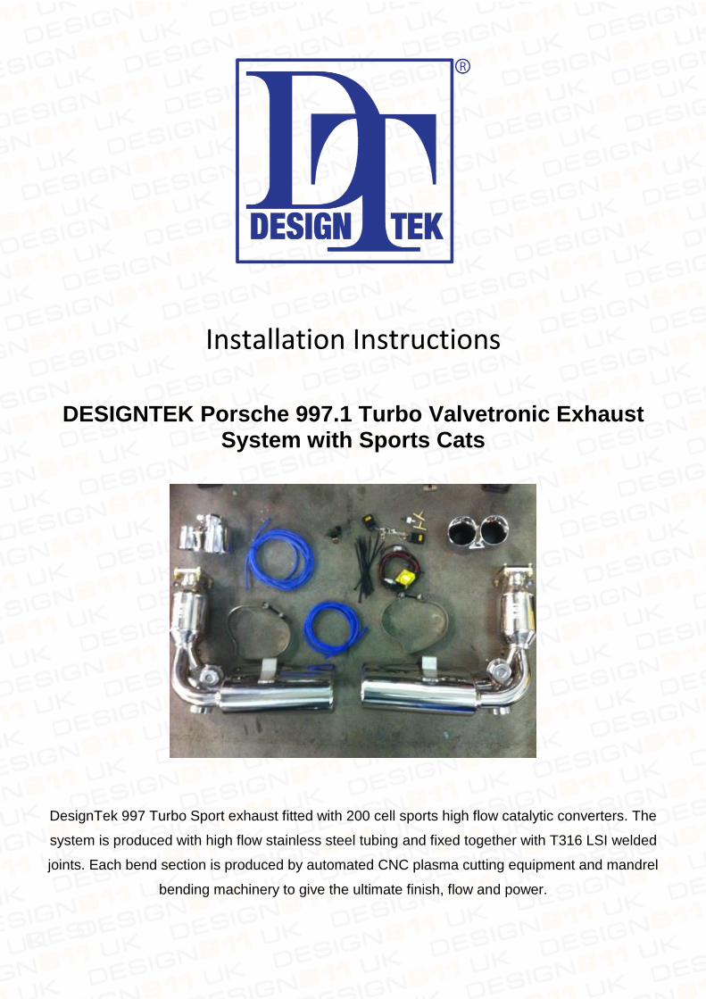
Installation Instructions
DESIGNTEK Porsche 997.1 Turbo Valvetronic Exhaust
System with Sports Cats
DesignTek 997 Turbo Sport exhaust fitted with 200 cell sports high flow catalytic converters. The
system is produced with high flow stainless steel tubing and fixed together with T316 LSI welded
joints. Each bend section is produced by automated CNC plasma cutting equipment and mandrel
bending machinery to give the ultimate finish, flow and power.
DesignTek Valvetronic Exhaust System 997.1 TURBO
www.DESIGN911.co.uk | www.DESIGNTEK.eu 2
Step 1: Raise vehicle to safe working height and if not on vehicle hoist install axle stands.
Step 2: Remove rear lights, Rear bumper, Rear crash bar, CAT heat shields and intercoolers.
Step 3: Remove all 4 Lambda sensors, and old Exhaust system.
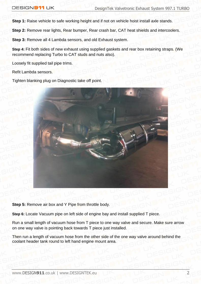
Step 4: Fit both sides of new exhaust using supplied gaskets and rear box retaining straps. (We
recommend replacing Turbo to CAT studs and nuts also).
Loosely fit supplied tail pipe trims.
Refit Lambda sensors.
Tighten blanking plug on Diagnostic take off point.
Step 5: Remove air box and Y Pipe from throttle body.
Step 6: Locate Vacuum pipe on left side of engine bay and install supplied T piece.
Run a small length of vacuum hose from T piece to one way valve and secure. Make sure arrow
on one way valve is pointing back towards T piece just installed.
Then run a length of vacuum hose from the other side of the one way valve around behind the coolant header tank round to left hand engine mount area.
DesignTek Valvetronic Exhaust System 997.1 TURBO
www.DESIGN911.co.uk | www.DESIGNTEK.eu 3
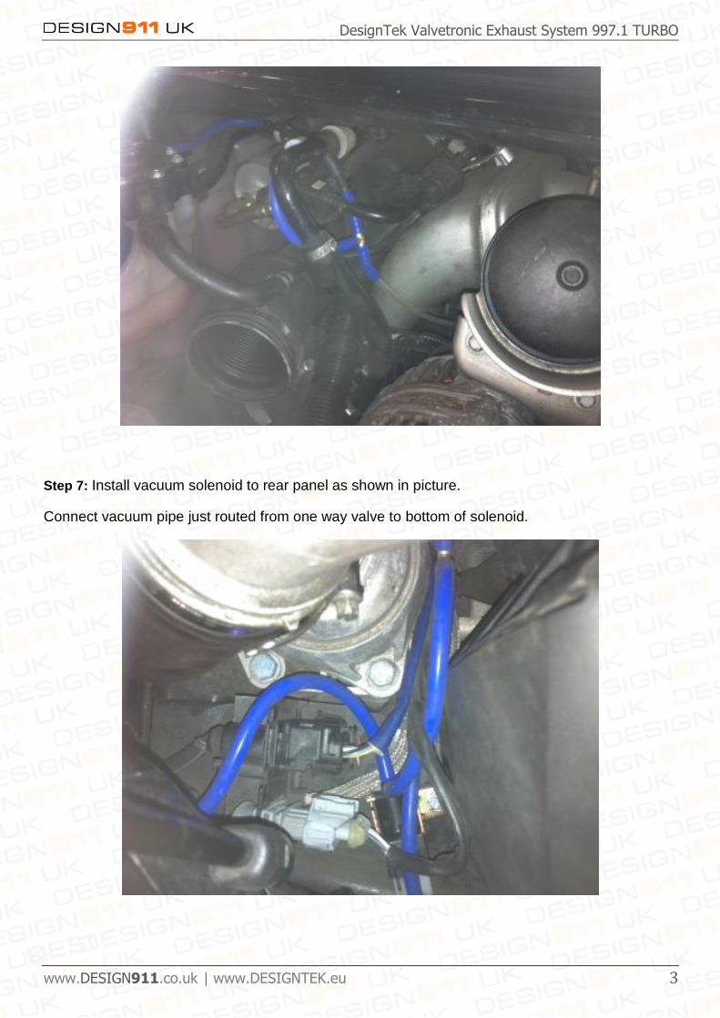
Step 7: Install vacuum solenoid to rear panel as shown in picture.
Connect vacuum pipe just routed from one way valve to bottom of solenoid.
DesignTek Valvetronic Exhaust System 997.1 TURBO
www.DESIGN911.co.uk | www.DESIGNTEK.eu 4
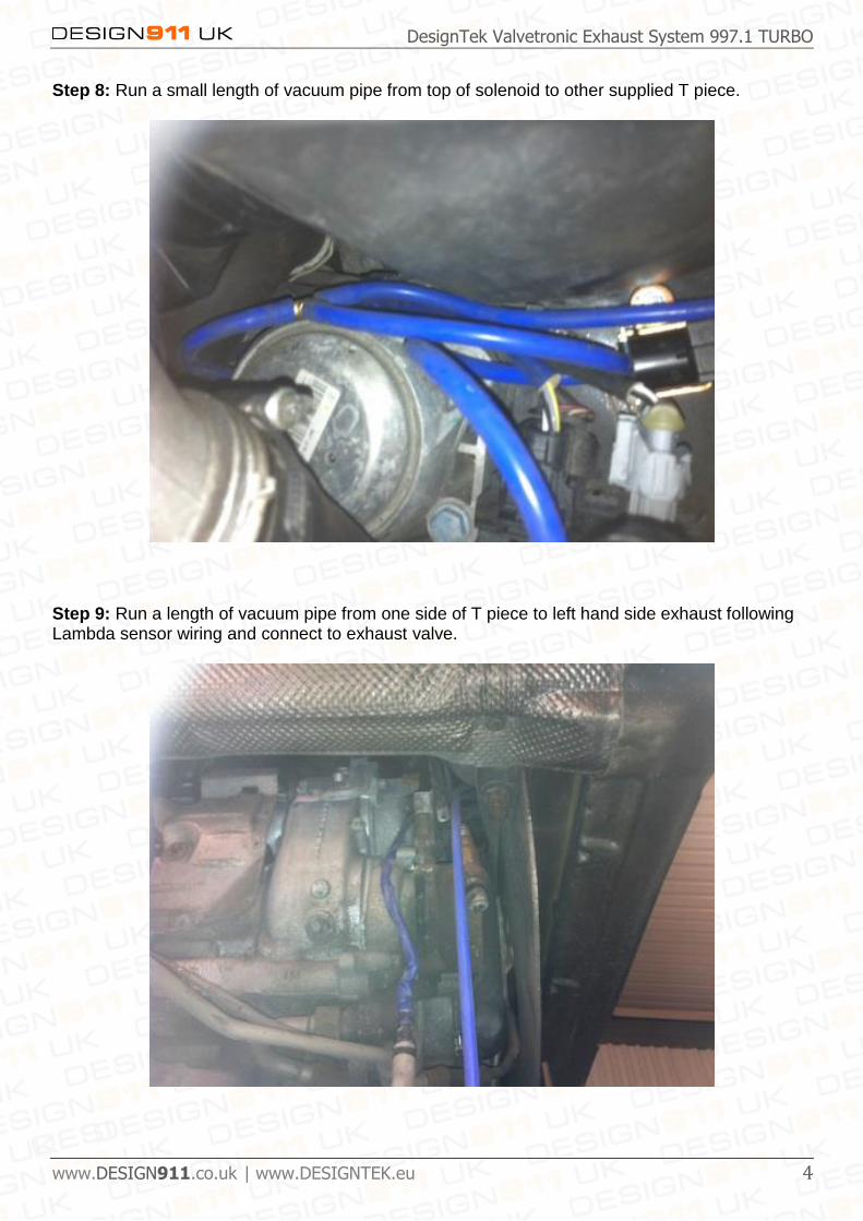
Step 8: Run a small length of vacuum pipe from top of solenoid to other supplied T piece.
Step 9: Run a length of vacuum pipe from one side of T piece to left hand side exhaust following Lambda sensor wiring and connect to exhaust valve.

DesignTek Valvetronic Exhaust System 997.1 TURBO
www.DESIGN911.co.uk | www.DESIGNTEK.eu 5
Step 10: Run a length of vacuum pipe from other side of T piece through behind engine cover latch to Right hand side of Exhaust following Lambda sensor wiring and connect to exhaust valve.
Step 11: Take control box and install on right hand side of engine bay onto main engine harness.
Run the thin black Ariel wire along loom away from engine.
Run the thicker black wire to a good Earth point. (Install a large ring connector and install on
engine mount fixing bolt).

DesignTek Valvetronic Exhaust System 997.1 TURBO
www.DESIGN911.co.uk | www.DESIGNTEK.eu 6
Step 12: Run the Red wire into the right hand bank air flow meter wiring rubber boot and solder to
RED and BLUE wire (pin 2) of air flow meter harness. (This is an ignition feed and doesn’t affect
the signal from air flow meter to ECU).
Step 13: Temporally install rear bumper and align rear exhaust tips and tighten in position.Once
happy with positon of tail pipes and tightened, remove rear bumper.
Step 14: Check all connections and fittings and secure as required.
Step 15: Refit all removed components in reverse order of removal.


![2.4 - Exhaust System, Cooling System, Turbo System [OCR]](https://img.pdfslide.us/doc/110x75/577cc3b21a28aba71196e38c/24-exhaust-system-cooling-system-turbo-system-ocr.jpg)