Embed Size (px)
Citation preview
Safety Messages to Installers and Users of Warning Light Equipment
People’s lives depend on your proper installation and operation of Federal Signal products. It is important to read and follow all instructions shipped with this product and the original product. Listed below are some other important safety instructions and precautions you should follow:
• To properly install this light, you must have a good understanding of automotive electrical procedures and systems, along with proficiency in the installation and service of safety warning equipment. Always refer to the vehicle’s service manuals when installing equipment on a vehicle.
• DO NOT install equipment or route wiring in the deployment path of an airbag.
• When drilling into a vehicle structure, be sure that both sides of the surface are clear of anything that could be damaged.
• For the light to function properly, a separate ground connection must be made. If practical, it should be connected to the negative battery terminal. At a minimum, it may be attached to a solid metal body or chassis part that provides an effective ground path.
• Locate the light control so the VEHICLE and CONTROL can be operated safely under all driving conditions.
• The effectiveness of an interior mounted warning light depends on the clarity, the tinting, and the angle of the glass it is placed behind. Tinting, dirt, defects, and steeply-angled glass reduce the light output of the warning light. This may reduce the effectiveness of the light as a warning signal. If your vehicle has dirty, tinted, or steeply-angles glass, use extra caution when driving your vehicle or blocking the right of way with your vehicle.
• Do not attempt to activate or deactivate the light control while driving in a hazardous situation.
• You should frequently inspect the light to ensure that it is operating properly and that it is securely attached to the vehicle.
• This product contains high intensity LED devices. To prevent eye damage, DO NOT stare into the light beam at close range.
• After installation, test the lights to ensure that they are operating properly.
• If a vehicle seat is temporarily removed, verify with the vehicle manufacturer if the seat needs to be recalibrated for proper airbag deployment.
• After testing is complete, provide a copy of these instructions to the instructional staff and all operating personnel.
• File these instructions in a safe place and refer to them when maintaining and/or reinstalling the product.
Failure to follow all safety precautions and instructions may result in property damage, serious injury, or death.
25500381 Rev. A4 1019
Installation Instructions for the XStream Interior Light Models XSMxx-xxx
Installation Instructions for the XStream Interior Light
Model XSMxx-xxx Federal Signal www.fedsig.com
2
Product OverviewThe SpectraLux XStream LED Series lightheads are low-current warning lights that are mounted only on the inside of the vehicle. The lighthead uses Solaris LED reflector technology to provide a bright and effective secondary warning signal. XStream models have 18 LEDs per head that can be ordered in various color combinations with a clear lens. Wire lead (Sync) and cigarette plug models are available.
All XStream models are designed for use with all Federal Signal switch controllers. The XStream is supplied with hardware for mounting the lighthead horizontally on the vehicle deck or dash. Additional bracket kits are available. The lightheads have an operating temperature of –30º C to +65º C (–22º F to +149º F).
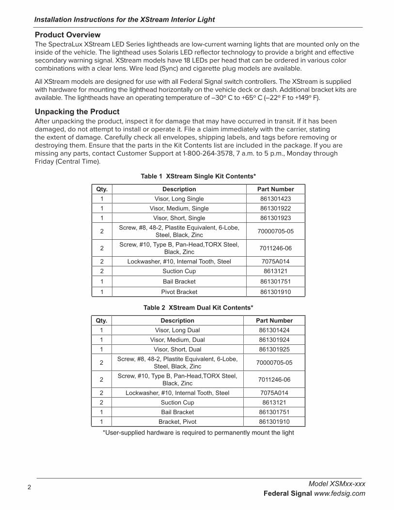
Unpacking the ProductAfter unpacking the product, inspect it for damage that may have occurred in transit. If it has been damaged, do not attempt to install or operate it. File a claim immediately with the carrier, stating the extent of damage. Carefully check all envelopes, shipping labels, and tags before removing or destroying them. Ensure that the parts in the Kit Contents list are included in the package. If you are missing any parts, contact Customer Support at 1-800-264-3578, 7 a.m. to 5 p.m., Monday through Friday (Central Time).
Table 1 XStream Single Kit Contents*
Qty. Description Part Number1 Visor, Long Single 8613014231 Visor, Medium, Single 8613019221 Visor, Short, Single 861301923
2 Screw, #8, 48-2, Plastite Equivalent, 6-Lobe, Steel, Black, Zinc 70000705-05
2 Screw, #10, Type B, Pan-Head,TORX Steel, Black, Zinc 7011246-06
2 Lockwasher, #10, Internal Tooth, Steel 7075A0142 Suction Cup 8613121
1 Bail Bracket 861301751
1 Pivot Bracket 861301910
Table 2 XStream Dual Kit Contents*
Qty. Description Part Number1 Visor, Long Dual 8613014241 Visor, Medium, Dual 8613019241 Visor, Short, Dual 861301925
2 Screw, #8, 48-2, Plastite Equivalent, 6-Lobe, Steel, Black, Zinc 70000705-05
2 Screw, #10, Type B, Pan-Head,TORX Steel, Black, Zinc 7011246-06
2 Lockwasher, #10, Internal Tooth, Steel 7075A0142 Suction Cup 86131211 Bail Bracket 8613017511 Bracket, Pivot 861301910
*User-supplied hardware is required to permanently mount the light
Installation Instructions for the XStream Interior Light
Model XSMxx-xxx Federal Signal www.fedsig.com
3
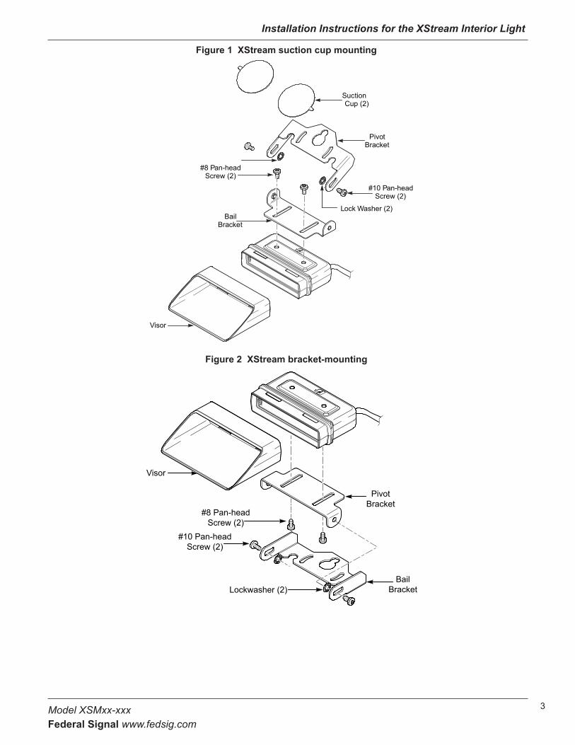
Figure 1 XStream suction cup mounting
Bail Bracket
Pivot Bracket
Suction Cup (2)
#10 Pan-head Screw (2)
Lock Washer (2)
#8 Pan-head Screw (2)
Visor
Figure 2 XStream bracket-mounting
Visor
#8 Pan-head Screw (2)
#10 Pan-head Screw (2)
Lockwasher (2)Bail
Bracket
Pivot Bracket
Installation Instructions for the XStream Interior Light
Model XSMxx-xxx Federal Signal www.fedsig.com
4
Installing the Lightheads
AIRBAG DEPLOYMENT: Do not install equipment or route wiring in the deployment path of an airbag. Failure to observe this warning will reduce the effectiveness of the airbag or potentially dislodge the equipment, causing serious injury or death.
LIGHT OUTPUT COMPLIANCE: This product is intended for supplemental warning in conjunction with an approved primary warning light system. Consult local codes and regulations to determine if the power supply/lighthead combination complies with the horizontal or vertical mount position required in your application. Failure to follow this warning could result in reducing the light output and its effectiveness as a warning system.
LIGHT HAZARD: To be an effective warning device, this product produces bright light that can be hazardous to your eyesight when viewed at a close range. Do not stare directly into this lighting product at a close range or permanent damage to your eyesight may occur.
Before installing the lights, read all instructions and plan all wiring and cable routing. To secure and protect the wiring, use grommets, wire ties, looms, and cable mounts (installer-supplied) as needed.
To install the lightheads: 1. Optional: Set a lighthead to control the flash patterns of one or more lightheads in the XStream system.
2. Mount the XStream system to the vehicle. See Mounting the Lighthead in a Vehicle.
3. Wire the XStream system to the vehicle.
4. Select a flash pattern for the controller lighthead.
Mounting the Lighthead in a VehicleThe light is installed using the supplied bracket and screws or suction cups. Determine the mounting position appropriate for the installation, and then select the applicable mounting method.Mounting the Light with Suction Cups
SUCTION CUPS ARE FOR TEMPORARY USE ONLY: Suction cup mounting is for temporary applications only. This unit should be removed from the vehicle and stored securely when not in use. Temperature changes and sunlight can cause suction cups to lose holding power. Periodically check the unit to be sure the suction cups have a firm grip on the mounting surface. An improperly secured light could fall off the windshield, causing injury and damage.
To mount the light with suction cups:
1. See Figure 1 on page 3. Attach the appropriate visor to the lighthead. Press the visor firmly until it snaps into place.
2. Attach the suction cups to the bracket.
3. Attach the pivot bracket to the lighthead using the supplied #8 pan-head screws. Do not overtighten.
4. Attach the bail bracket to the pivot bracket with the supplied #10 pan-head screws and lockwashers. The lockwashers go between the bail and the pivot bracket.
5. Apply the suction cups to the glass.
Installation Instructions for the XStream Interior Light
Model XSMxx-xxx Federal Signal www.fedsig.com
5
Mounting the Light with the Bracket To mount the light with a bracket:
1. Select a mounting location for the light and best orientation of the brackets.
2. See the figures on page 3. Attach the appropriate visor to the lighthead. Press the visor firmly to snap it into place.
3. Attach the pivot bracket to the lighthead using the supplied #8 pan-head screws. Do not overtighten.
4. Attach the bail bracket to the pivot bracket with the supplied #10 pan-head screws and lockwashers. The lockwashers go between the bail and the pivot bracket.
5. Attach the bail bracket to the vehicle using the appropriate user supplied hardware.
Wiring and Programming the LightXStream lights are available as cigarette plug or synchronizable models.
Wire Functions of Cigarette Plug ModelsRED WIRE: Memory 1 (to + Vdc) (red switch on cigarette plug)
WHITE WIRE: Steady Flood (to +Vdc) (green switch on cigarette plug)
Dual head only: Press S1 to change which heads are steady flood.
Cigarette plug models are distinguished by the letter C in the part number.
Wire Functions of Synchronizable ModelsSync models have three additional wires:
BROWN WIRE: Memory 2 (to +Vdc)
GREEN WIRE: Sync/Program
To synchronize the lights, set them to the same color mode and flash pattern and connect the green wires. Do not sync patterns 8, 9, or 10.
BLACK WIRE: GND (to – chassis ground)
Color DesignationsThe color codes in the model number correspond to the colors listed below:
For example Model XSM1-BRW
COLOR1 = B (Blue)
COLOR2 = R (Red)
COLOR3 = W (White)
Code List: B = Blue, R = Red, W = White, A = Amber, G = Green
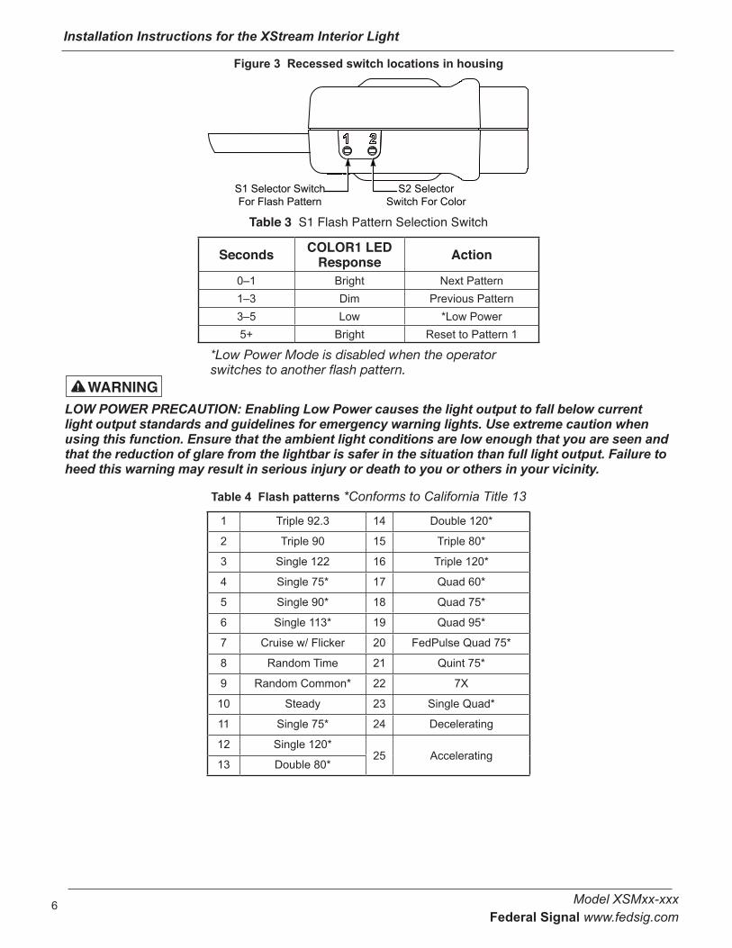
Configuring the LightSee Figure 3 on page 6. Two recessed switches in the side of the housing enable you to configure how the light operates. Switch S1 displays and sets the flash pattern. Switch S2 displays and sets the color mode. You can also configure the light for Low Power Mode. A small precision screwdriver or paperclip is required to access the switches. To select an action in Table 3, press S1 for the duration listed in the Seconds column. To confirm your selection, the LEDs respond as shown in the table. For a list of flash patterns, see Table 4.
Installation Instructions for the XStream Interior Light
Model XSMxx-xxx Federal Signal www.fedsig.com
6
Figure 3 Recessed switch locations in housing
S1 Selector Switch For Flash Pattern
S2 Selector Switch For Color
Table 3 S1 Flash Pattern Selection Switch
Seconds COLOR1 LED Response Action
0–1 Bright Next Pattern1–3 Dim Previous Pattern3–5 Low *Low Power5+ Bright Reset to Pattern 1
*Low Power Mode is disabled when the operator switches to another flash pattern.
LOW POWER PRECAUTION: Enabling Low Power causes the light output to fall below current light output standards and guidelines for emergency warning lights. Use extreme caution when using this function. Ensure that the ambient light conditions are low enough that you are seen and that the reduction of glare from the lightbar is safer in the situation than full light output. Failure to heed this warning may result in serious injury or death to you or others in your vicinity.
Table 4 Flash patterns *Conforms to California Title 13
1 Triple 92.3 14 Double 120*
2 Triple 90 15 Triple 80*
3 Single 122 16 Triple 120*
4 Single 75* 17 Quad 60*
5 Single 90* 18 Quad 75*
6 Single 113* 19 Quad 95*
7 Cruise w/ Flicker 20 FedPulse Quad 75*
8 Random Time 21 Quint 75*
9 Random Common* 22 7X
10 Steady 23 Single Quad*
11 Single 75* 24 Decelerating
12 Single 120*25 Accelerating
13 Double 80*
Installation Instructions for the XStream Interior Light
Model XSMxx-xxx Federal Signal www.fedsig.com
7
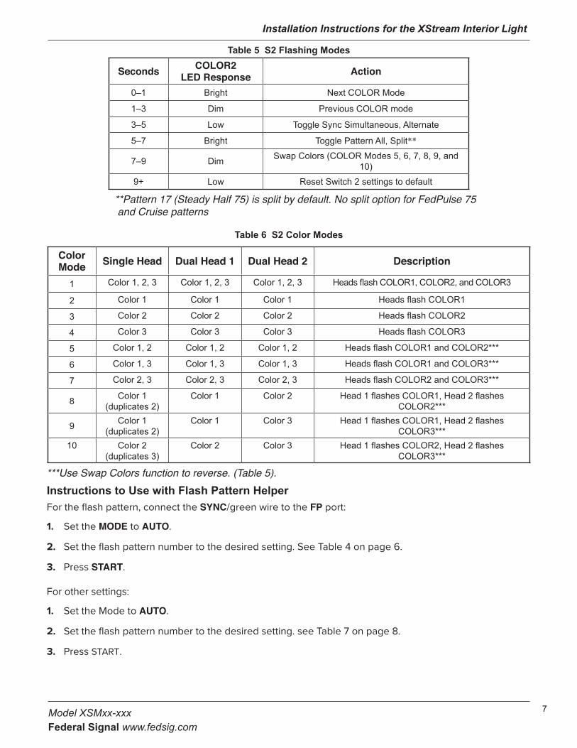
Table 5 S2 Flashing Modes
Seconds COLOR2 LED Response Action
0–1 Bright Next COLOR Mode
1–3 Dim Previous COLOR mode
3–5 Low Toggle Sync Simultaneous, Alternate
5–7 Bright Toggle Pattern All, Split**
7–9 Dim Swap Colors (COLOR Modes 5, 6, 7, 8, 9, and 10)
9+ Low Reset Switch 2 settings to default
**Pattern 17 (Steady Half 75) is split by default. No split option for FedPulse 75 and Cruise patterns
Table 6 S2 Color Modes
Color Mode Single Head Dual Head 1 Dual Head 2 Description
1 Color 1, 2, 3 Color 1, 2, 3 Color 1, 2, 3 Heads flash COLOR1, COLOR2, and COLOR3
2 Color 1 Color 1 Color 1 Heads flash COLOR1
3 Color 2 Color 2 Color 2 Heads flash COLOR2
4 Color 3 Color 3 Color 3 Heads flash COLOR3
5 Color 1, 2 Color 1, 2 Color 1, 2 Heads flash COLOR1 and COLOR2***
6 Color 1, 3 Color 1, 3 Color 1, 3 Heads flash COLOR1 and COLOR3***
7 Color 2, 3 Color 2, 3 Color 2, 3 Heads flash COLOR2 and COLOR3***
8 Color 1 (duplicates 2)
Color 1 Color 2 Head 1 flashes COLOR1, Head 2 flashes COLOR2***
9 Color 1 (duplicates 2)
Color 1 Color 3 Head 1 flashes COLOR1, Head 2 flashes COLOR3***
10 Color 2 (duplicates 3)
Color 2 Color 3 Head 1 flashes COLOR2, Head 2 flashes COLOR3***
***Use Swap Colors function to reverse. (Table 5).Instructions to Use with Flash Pattern Helper For the flash pattern, connect the SYNC/green wire to the FP port:
1. Set the MODE to AUTO.
2. Set the flash pattern number to the desired setting. See Table 4 on page 6.
3. Press START.
For other settings:
1. Set the Mode to AUTO.
2. Set the flash pattern number to the desired setting. see Table 7 on page 8.
3. Press START.
Installation Instructions for the XStream Interior Light
Model XSMxx-xxx Federal Signal www.fedsig.com
8
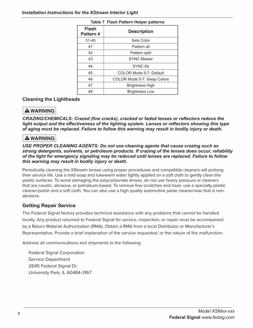
Table 7 Flash Pattern Helper patternsFlash
Pattern # Description
31-40 Sets Color41 Pattern all 42 Pattern split43 SYNC Master
44 SYNC Alt
45 COLOR Mode 5-7: Default46 COLOR Mode 5-7: Swap Colors47 Brightness High48 Brightness Low
Cleaning the Lightheads
CRAZING/CHEMICALS: Crazed (fine cracks), cracked or faded lenses or reflectors reduce the light output and the effectiveness of the lighting system. Lenses or reflectors showing this type of aging must be replaced. Failure to follow this warning may result in bodily injury or death.
USE PROPER CLEANING AGENTS: Do not use cleaning agents that cause crazing such as strong detergents, solvents, or petroleum products. If crazing of the lenses does occur, reliability of the light for emergency signaling may be reduced until lenses are replaced. Failure to follow this warning may result in bodily injury or death.
Periodically cleaning the XStream lenses using proper procedures and compatible cleaners will prolong their service life. Use a mild soap and lukewarm water lightly applied on a soft cloth to gently clean the plastic surfaces. To avoid damaging the polycarbonate lenses, do not use heavy pressure or cleaners that are caustic, abrasive, or petroleum-based. To remove fine scratches and haze, use a specialty plastic cleaner/polish and a soft cloth. You can also use a high quality automotive paste cleaner/wax that is non-abrasive.
Getting Repair ServiceThe Federal Signal factory provides technical assistance with any problems that cannot be handled locally. Any product returned to Federal Signal for service, inspection, or repair must be accompanied by a Return Material Authorization (RMA). Obtain a RMA from a local Distributor or Manufacturer’s Representative. Provide a brief explanation of the service requested, or the nature of the malfunction.
Address all communications and shipments to the following:
Federal Signal Corporation Service Department 2645 Federal Signal Dr. University Park, IL 60484-3167