Embed Size (px)
Citation preview

Lingenfelter Performance Engineering1557 Winchester Road
Decatur, IN 46733(260) 724-2552
(260) 724-0422 faxwww.lingenfelter.com
Revision - 1.6 Release date 13 June 2016
Installation instructions for the Lingenfelter 2010-2015 Camaro SS, 2012-2015 ZL1 Camaro,
and 2014-2015 Chevy SSFuel Pump Voltage Booster Kit
PN: L460111410

Page 2
Parts ListLingenfelter 2010-2015 Camaro SS, 2012-2015 ZL1 Camaro, and 2014-2015 Chevy SS
Boost-A-Pump (BAP) kit L460111410 # Description Part number 1 Boost-A-Pump 40A TT KB89069 1 Pressure switch connector harness 12101901 1 BAP pressure switch bracket L960200000 1 1/8” 90 degree pipe nipple 44555K147 7 12 gauge red wire 7’ 732602RED 7 1/4” hi temperature loom 7’ 1773 4 Vacuum hose 4’ HT-21503-10 5 Self tapping screws AV12351 6 2 sided hook and loop tape 6” O6483 1 In-line fuse cover CE-423004 1 In-line fuse connector CE-423005 2 Fuse terminal CE-504005 1 Eyelet connector (yellow) BARNES-23830 1 30A fuse (green) BARNES-7560-A 1 1/8” heat shrink (1 ft) 1 Lingenfelter 9” decal L920010000 1 installation instructions
• Wire tool• Crimping tool• Pliers• Drill• Heat gun• Thread sealant
Tools & Materials Required• 3/16” drill bit• 10 mm socket• Ratchet• Electrical tape• Wire stripping tool• Pin tool
Optional Parts # Description Part number 1 Vacuum switch LF20-V-211110-S 1 RPM activated switch L460040000 1 High current sealed relay kit, 40 AMP SPDT L450100000
NOTE: The installation procedure listed is for the 2010-2015 Camaro. The installation procedure for the 2014-2015 Chevy SS is similar. However, the mounting locations will be different.
Page 3
Thefuelpumpvoltageboosterincreasesfuelflowbyincreasingthevoltagetothefuelpump,increasing the RPM of the fuel pump motor. Graphs can be found on page 16-17 that shows the fuel flowatanormal13.5voltchargingsystemvoltageandat17volts(CamaroSS,page16andZL1Camaro, page 17).
This fuel pump voltage booster kit offers a fuel pump voltage setting of 17 volts. 17 volts is the maximum we recommend for the stock 2010-2015 Camaro fuel pump and the factory fuel pump controller. 15 volts is the max voltage for the Lingenfelter twin pump set up, any more and the pumps will draw too much current for the fuel pump controller. This voltage booster will not work in the Lingenfelter twin pump application. The production fuel pump controller monitors fuel pump voltage and current and could set a diagnostic code at higher voltages and current loads.
Why are we voltage boosting the fuel pump controller and the fuel pump and not just the fuel pump? The reason this is done is that the fuel pump voltage booster increases the voltage out but in order to do so it has to increase the amount of current it draws on the low voltage, input side of the voltage booster. For example, if you are outputting 17 volts and 15 amps to the pump that is 255 watts output (17x15=255). In order to output 255 watts you must draw 19 amps at 13.5 volts(255/13.5=19).Thisassumes100%efficiencyofthevoltagebooster.Atamorerealistic85%efficiency,youarenowdrawing22amps.Ifwehadthevoltageboosterbetweenthepumpandthefuel pump controller, the fuel pump controller would have to operate at these elevated current levels, causing heat and other reliability related problems. By having the fuel pump controller also operating at elevated voltage the fuel pump controller doesn’t see the higher current level on the low voltage side of the fuel pump booster, reducing durability and diagnostic code problems.
Fuelflowrequirementsdependontheefficiencyofyourengine(brakespecificfuelconsumption,BSFC). As a general guide, for supercharged applications over roughly 525 hp (at the crank), we recommend voltage boosting the factory pump and for naturally aspirated applications over roughly 600 hp we recommend voltage boosting the factory pump. The voltage boosted Camaro SS factory pump can support between 650 hp (supercharged or turbocharged applications) to 750 hp (naturally aspirated applications). The voltage boosted ZL1 Camaro factory pump can support up to 750 hp (supercharged or turbocharged applications). For higher power applications, we recommend our Camaro dual fuel pump system.
Read the entire instruction manual before beginning installation. Some stock parts will be used in reassembly. Estimated installation time is two hours.
When referencing the side of the vehicle in these instructions, the driver side of the vehicle is considered the left side and the passenger side of the vehicle is considered the right side of the vehicle.
Steps 33 and 34 are for a boost triggered (turbocharged or supercharged) application. Refer to steps 35 - 48 for naturally aspirated applications. A wiring diagram for the Boost-A-Pump (BAP) kit in a 2010-2015 Camaro can be found on page 14. If you would like the BAP to be RPM activated or RPM and vacuum/boost activated, refer to page 15.
Make sure that the BAP is connected to a good clean ground free of paint, rust or other material. Damage to the unit can occur if a good ground is not used. If you are using a different ground than what the instructions specify, be sure to properly clean and prep the area or use another existing ground.
CARRY A SPARE 30 A FUSE WITH YOU AT ALL TIMES!!! If the fuse blows, the fuel pump will no longer work and your vehicle will no longer run.

Page 4
4. Cut the power wire in the position indicated. Be sure to cut between the BAP module and as close to the fuse holder as shown. This is the battery feed wire for the BAP
3. Raise the vehicle with a vehicle hoist or a jack and jackstands. Be careful to follow the GM lifting procedures on the 2010-2015 Camaro due to the aerodynamic components being easily damaged and the low ride height of the vehicle. Refer to your owner’s manual for correct vehicle lifting procedures.
1. Disconnect your negative battery terminal located in the trunk of the car after removing the trunk carpet lining.
2. Open the hood of the vehicle. If you have been driving the vehicle, allow the vehicle to cool down for a few hours before starting this installation.
Page 5
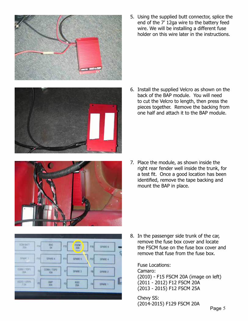
5. Using the supplied butt connector, splice the end of the 7’ 12ga wire to the battery feed wire. We will be installing a different fuse holder on this wire later in the instructions.
7. Place the module, as shown inside the right rear fender well inside the trunk, for atestfit.Onceagoodlocationhasbeenidentified,removethetapebackingandmount the BAP in place.
6. Install the supplied Velcro as shown on the back of the BAP module. You will need to cut the Velcro to length, then press the pieces together. Remove the backing from one half and attach it to the BAP module.
8. In the passenger side trunk of the car, remove the fuse box cover and locate the FSCM fuse on the fuse box cover and remove that fuse from the fuse box.
Fuse Locations:Camaro:(2010) - F15 FSCM 20A (image on left)(2011 - 2012) F12 FSCM 20A(2013 - 2015) F12 FSCM 25A
Chevy SS:(2014-2015) F129 FSCM 20A

Page 6
9. Using a small screwdriver, pop the fuse box out of it’s base and, using a pin tool remove the FSCM wire (circuit 2640) from the pin location listed below. Cut the terminal off and strip the end of the wire.
Pin Locations:Camaro:(2010) - D6 (RD/WH)(2011 - 2015) - A5 (RD/WH)
Chevy SS:(2014-2015) - Connector X1 Pin 28 (RD/VT)
11. Install the insulated ring terminal to the ground wire on the Boost-A-Pump (BAP) module.
10. Locate the red output wire from the BAP module (not the battery feed wire). Cut to length, splice, solder and heat shrink it to the FSCM wire.
12. Install the ground wire running off of the BAP module to the factory ground located to the right of the fuse box.

Page 7
15. Strip the end of the BAP power wire, approximately 1/4”-3/8” down. Insert the stripped wire through one of the holes on the in-line fuse connector.
14. Run the BAP power wire along the factory wiring harness as shown, and cut to length at the new fuse holder location. Save the wire that is removed.
13. This picture shows the recommended mounting location, for the Lingenfelter supplied fuse holder.
16. Using a crimping tool, crimp one of the supplied terminals onto the wire and pull the terminal back into the connector to seat it into place.
Page 8
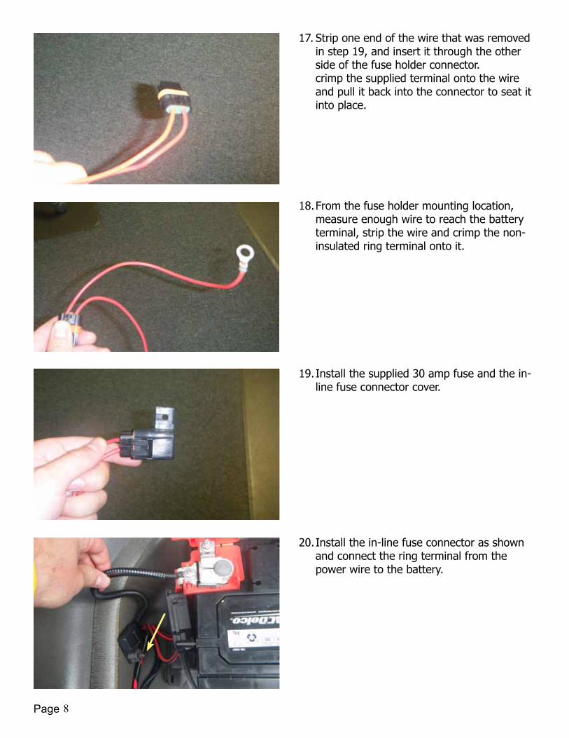
17. Strip one end of the wire that was removed in step 19, and insert it through the other side of the fuse holder connector. crimp the supplied terminal onto the wire and pull it back into the connector to seat it into place.
18. From the fuse holder mounting location, measure enough wire to reach the battery terminal, strip the wire and crimp the non-insulated ring terminal onto it.
19. Install the supplied 30 amp fuse and the in-line fuse connector cover.
20. Install the in-line fuse connector as shown and connect the ring terminal from the power wire to the battery.
Page 9
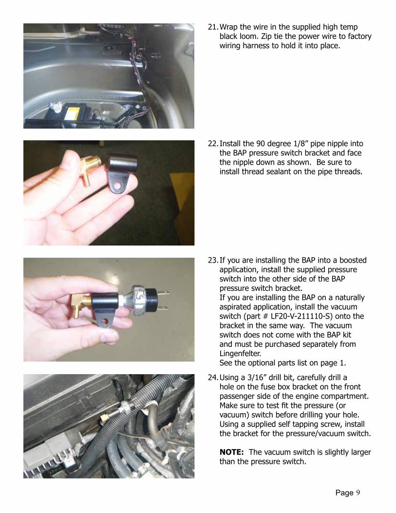
22. Install the 90 degree 1/8” pipe nipple into the BAP pressure switch bracket and face the nipple down as shown. Be sure to install thread sealant on the pipe threads.
23. If you are installing the BAP into a boosted application, install the supplied pressure switch into the other side of the BAP pressure switch bracket. If you are installing the BAP on a naturally aspirated application, install the vacuum switch (part # LF20-V-211110-S) onto the bracket in the same way. The vacuum switch does not come with the BAP kit and must be purchased separately from Lingenfelter. See the optional parts list on page 1.
21. Wrap the wire in the supplied high temp black loom. Zip tie the power wire to factory wiring harness to hold it into place.
24. Using a 3/16” drill bit, carefully drill a hole on the fuse box bracket on the front passenger side of the engine compartment. Makesuretotestfitthepressure(orvacuum) switch before drilling your hole. Using a supplied self tapping screw, install the bracket for the pressure/vacuum switch. NOTE: The vacuum switch is slightly larger than the pressure switch.

Page 10
25. Locate the supercharger boost reference port (on the back of the supercharger by the fuel rail on a Magnuson application). For otherboostedapplications,findasimilarboost reference port. NOTE: For systems that use a vacuum switch, locate a manifold vacuum port.
26. For some applications an existing vacuum/boost reference hose must be used in conjunctionwitha“T”fitting.Cuttheexisting hose in a convenient location and inserta“T”fittingintothenowopenendsof the hose.
27. Connect one end of the supplied 4’ vacuum hose to the supercharger boost reference portorTeefitting.
28. Guide the vacuum hose under the fuel rail and along the top of the cylinder head directly under the wiring harness. Install the hose to the 90 degree nipple. NOTE: High boost applications should use a Oetiker hose clamp.

Page 11
30. Thisislocatedoverthemuffleronthepassenger side underneath the vehicle.
31. Route the wire up to the front of the vehicle, tie wrapping it around the fuel lines every 1-2 feet. Route the wire behind the heat shield, as shown, to the pressure or vacuum switch.
29. Locate the rubber grommet in your trunk located on the passenger side next to the vent. Drill or cut out the center as shown. Slide the end of the activation cable, with red and black wires from the BAP module, down through the drilled or cut hole in the grommet.
32. Steps 33 and 34 are for using a boost pressure switch as the trigger method. If you are using a vacuum switch for a naturally aspirated car, use 38 to 41 cut the activation cable to length, about 3 inches from the pressure switch. Remove the middle wire on the pressure switch electrical connector as shown. Use heat shrink to cover the exposed end. cut the remaining 2 wires down to about 3 inches in length.

Page 12
33. Using the butt splice connectors supplied with the kit, Connect the remaining wires from the pressure switch connector to the red and black wires in the activation cable. The polarity of the wires is not critical. Use a heat gun to seal the connectors after they have been crimped. Connect the electrical connector to the pressure switch. Go to step 38
34. Steps 35 to 38 are for vacuum triggered applications and require optional components. Some pictures show the switch off of the vehicle without the bracket installed, this is for illustrative purposes only. Cut the activation cable to length, about 2 inches past the vaccuum switch. Using crimping tool install insulated female spade terminals, on the red and black wires.
35. Install the wires onto the vacuum switch (part # LF20-V-211110-S). The wires can be connected to either terminal on the vacuum switch, polarity is not critical
36. Connect one end of the vacuum hose to a manifold vacuum source. Route the hose safely away from heat and moving parts and connect to the 90 degree 1/8 inch nipple. At this point you should have the bracket and vacuum line installed, wiring installed and the cover on the end of the vacuum switch.

Page 13
37. Re-install your negative battery terminal to your battery and your interior in your trunk Removed in step 1. Remove your jack and jackstands and start your vehicle. You have completed the installation process.

Page 14
Wiring diagram
of Boost-A
-Pump m
odule

Page 15
BA
P with R
PM activated sw
itch wiring diagram
BAP
FSCM
BATTERY
PRESSURE/VA
CUUM
SOURC
E
RPM SW
ITCH
CO
IL PAC
K A
CTIV
ATIO
N
WIRE TO
RPM
SWITC
H (W
HITE WIRE)
CO
IL PA
CK
+-
CA
P OFF G
REY WIRE
40A RELA
Y +12 V KEY-
ON
POW
ER+12 V
KEY-O
N PO
WER
PRESSURE/VA
CUUM
SWITC
H
30A FUSE
DCBAA B C D
12
34
56
78 8
76
54
32
1
THE INFO
RMA
TION
CO
NTA
INED
IN THIS
DRA
WIN
G IS THE SO
LE PROPERTY O
FLIN
GEN
FELTER PERFORM
AN
CE EN
GIN
EERING
. A
NY REPRO
DUC
TION
IN PA
RT OR A
S A W
HOLE
WITHO
UT THE WRITTEN
PERMISSIO
N O
FLIN
GEN
FELTER PERFORM
AN
CE EN
GIN
EERING
IS PROHIBITED
.
PROPRIETA
RY AN
D CO
NFIDEN
TIAL
DIM
ENSIO
NS A
RE IN IN
CHES
TOLERA
NC
ES:FRA
CTIO
NA
L: 1/64
AN
GULA
R: MA
CH:
0.5 BEND
O
NE PLA
CED
DEC
IMA
L: 0.010
TWO
PLAC
E DEC
IMA
L: 0.005
THREE PLAC
E DEC
IMA
L: 0.001
INTERPRET G
EOM
ETRICTO
LERAN
CIN
G PER:
MA
TERIAL
FINISH
----
DRA
WN
CHEC
KED
ENG
APPR.
MFG
APPR.
Q.A
.
CO
MM
ENTS:
DA
TEN
AM
E
1557 Winchester R
d, Decatur, IN
46733 P. 260-724-2552TITLE:
SIZE
BPA
RT NO
.REV
SHEET 1 OF 2
WEIG
HT:SC
ALE: 1:1
REVISION
S
REV.D
ESCRIPTIO
ND
ATE
APPRO
VED
UNLESS O
THERWISE SPEC
IFIED:

Page 16
0 50
100
150
200
250
300
350
010
2030
4050
6070
8090
100
Flow (lph)
Pressure (psi)
Stock 2010 C
amaro S
S fuel pum
p module
(complete m
odule with secondary transfer jet functioning)
13.5 vdc, 190 lph @ 60 psi
17.0 vdc, 260 lph @ 60 psi
LPH
(13.5 vdc)
LPH
(17.0 vdc)

Page 17
0 50
100
150
200
250
300
350
400
450
500
010
2030
4050
6070
8090
100
Flow (lph)
Pressure (psi)
Stock 2012 Z
L1 Cam
aro/Caprice P
PV
fuel pump m
odule(com
plete module w
ith secondary transfer jet functioning)13.5 vdc, 260 lph @
60 psi17.0 vdc, 370 lph @
60 psi
LPH
(13.5 vdc)
LPH
(17.0 vdc)

Page 18
2010-2015 Camaro Fuel Pump Voltage Booster Kit v1.6.indd
NOTICES:It is the responsibility of the purchaser to follow all guidelines and safety procedures supplied with this product and any other manufacture’s product used with this product.
Lingenfelter Performance Engineering assumes no responsibility for damages resulting from accident, improper installation, misuse, abuse, improper operation, lack of reasonable care, or all previously stated reasons due to incompatibility with other manufacturer’s products.
Lingenfelter Performance Engineering assumes no responsibility or liability for damages incurred from the use of products manufactured or sold by Lingenfelter Performance Engineering on vehicles used for competition racing.
Itisthepurchaser’sresponsibilitytocheckthestateandlocallawsandsanctioningbodyrequirementspertainingtotheuse of this product for racing applications. Lingenfelter Performance Engineering does not recommend nor condone the use of its products for illegal street racing.
For additional product installation information and technical support, contact LPE or your LPE products distributor. You can also find technical support and usage discussions regarding this product and many other LPE products in our Internet forums:
http://www.lingenfelter.com/LPEforumfiles
Follow us on Facebook!
http://www.facebook.com/home.php#!/lpehp
Lingenfelter Performance Engineering1557 Winchester Road
Decatur, IN 46733(260) 724-2552
(260) 724-8761 faxwww.lingenfelter.com