Embed Size (px)
Citation preview

Lingenfelter Performance Engineering1557 Winchester Road
Decatur, IN 46733(260) 724-2552
(260) 724-8761 faxwww.lingenfelter.com
Revision - 2.1 Release date 14-January-2012
Installation Instructions for the Lingenfelter2010-2012 Camaro SS Twin Fuel Pump System
PN: L710071410 & L710081410

Page 1.
Parts List2010-2012 Camaro SS Lingenfelter Twin Fuel Pump System, Electronic Pressure Control
PN L710071410 # Description Part number 1 Twin pump module assembly XX03547-0005 1 Secondary module assembly XX03547-0001 1 Internal transfer tube 92203244 6 Small Zip tie (black) 2 Heat shrink butt connectors DC-981005 1 External fuel pump module harness L760041410 1 Fuel pump control module, programmed 1 Fuel pump control module connector 19168025 2 Float connector wire terminal 54001800 4 Fuel pump controller terminal 15476168 1 Oeticker clamp 52545-K45 1 Primary fuel pump module O-ring seal 2 10mm X 1” self tapping screws TS-TEK1016 1 Lingenfelter decal L920010000 1 Instructions
2010 Camaro SS Lingenfelter Twin Fuel Pump System, Mechanical Pressure Regulator PN L710081410
# Description Part number 1 Mechanical regulator twin pump module assembly XX03547-0003 1 Secondary module assembly XX03547-0001 1 Internal transfer tube 92203244 6 Small Zip tie (black) 2 Heat shrink butt connectors DC-981005 1 External fuel pump module harness L760041410 2 Float connector wire terminal 54001800 1 Oeticker clamp 52545-K45 1 Primary fuel pump module O-ring seal 1 Lingenfelter decal L920010000 1 Instructions
• Pin tools• J 45004 Kent Moore siphon (or equivalent)• Fuel pressure tester/drain tool• J 45722 fuel sender lock ring wrench (or equivalent)• CH 48482 fuel sender lock ring wrench (or equivalent)• Insulated connector crimping tool
Tools & Materials Required
• Electrical tape• Scan/diagnostics tool• Razor blade• Oeticker clamp crimping tool (or side cutters)• EFILive V2 Tuner Interface• Fire extinguisher
Read the entire instruction manual before beginning installation. Some stock parts will be used in reassembly.
After installing the LPE Camaro Twin Fuel Pump System, refer to the Addendum for instructions on how to re-calibrate the fuel level sensors. If the fuel level sensors are not re-calibrated, the vehicle’s fuel gauge will be inaccurate.

Page 2.
Terminology- The primary module is the fuel pump module on the passenger side that has a pump and level sensor. The secondary module is the module on the driver side that has a transfer pick up tube and a level sensor without an active pump. When referencing the side of the vehicle, the driver side of the vehicle is considered the left side and the passenger side of the vehicle is considered the right side of the vehicle. Your 5th generation Camaro’s fuel pressure is regulated by a process called “pulse width modulation” (PWM). This process increases fuel pump life by modulating the fuel pump in short on/off cycles as fuel pressure changes. If you are changing the fuel pressure regulation method to a mechanical system please read carefully as you will only perform certain steps in the instruction manual.
NOTE: It is easier to start with a nearly empty fuel tank for this installation.
For detailed instructions on removing and installing the production GM components, LPE recommends having access to the online GM service information or purchasing a GM production service manual. Electronic service information is available from AC Delco. Printed service manuals are available from Helms at www.helminc.com.
Warning: Gasoline vapors are highly flammable. A fire could occur if an ignition source is present. Never drain or store gasoline in an open container due to the possibility of fire or explosion. Have a dry chemical (Class B) fire extinguisher nearby and always wear appropriate safety equipment.
1. You are now going to bleed your fuel pressure. The GM recommended way to bleed the pressure is by installing a scan tool onto your engine diagnostics port and commanding your fuel pump relay off. If you do not have a scan tool, refer to step 2. After turning your relay off, start your vehicle and let it idle until the engine shuts off (usually around 20-30 seconds). Turn the key to the off position and check for little to no fuel pressure. If fuel pressure remains in the system, repeat this step.
2. You may also relieve the pressure by the fuel pressure test port on your fuel rail located on the driver side of the engine. Remove the cap that is on the test port and bleed the pressure using a pressure tester/bleed off tool. NOTE: Be sure to have a device to catch your excess fuel in the fuel rail.

Page 3.
3. Remove the fuel filler cap to reduce the pressure build up in the tank.
4. Raise the vehicle with a vehicle hoist or a jack and jackstands. Be careful to follow the GM lifting procedures on the 2010-2011 Camaro due to the aerodynamic components being easily damaged and the low ride height of the vehicle. Refer to your owner’s manual for correct vehicle lifting procedures.
5. Remove the exhaust from the rear of the vehicle to allow access to the tank. This illustration shows the passanger side exhaust pipe clamp. The driver side exhaust bracket needs to be removed as well.
6. Un-install the chassis stiffening bracket by removing the four (4) bolts shown.

Page
7. Remove the propeller shaft (a.k.a. driveshaft). This is done using an E18 inverted Torx socket and a 18mm socket for the front mounting bolts, and a 21mm socket for the rear mounting bolts.
8. Remove the two (2) 10 mm mounting nuts holding the front heat sheild in place.
9. Remove the four (4) 10 mm bolts holding the heat sheild closest to the gas tank.
10. Remove the two (2) front mounting 24 mm bolts of the rear subframe. You may want to use a jack to slowely lower the front of the subframe. This step provides clearance to remove the tank from the vehicle.
4.

Page 5.
11. Remove the parking brake cables. The cable shown simply pops off of the black bracket.
12. Disconnect the evaporative emission lines.
13. Disconnect the vent solenoid electrical connector.
14. Loosen the hose clamp (red arrow) and remove the fuel filler tubeas, also un-clip and disconnect the vent tube (yellow arrow).
Page 6.
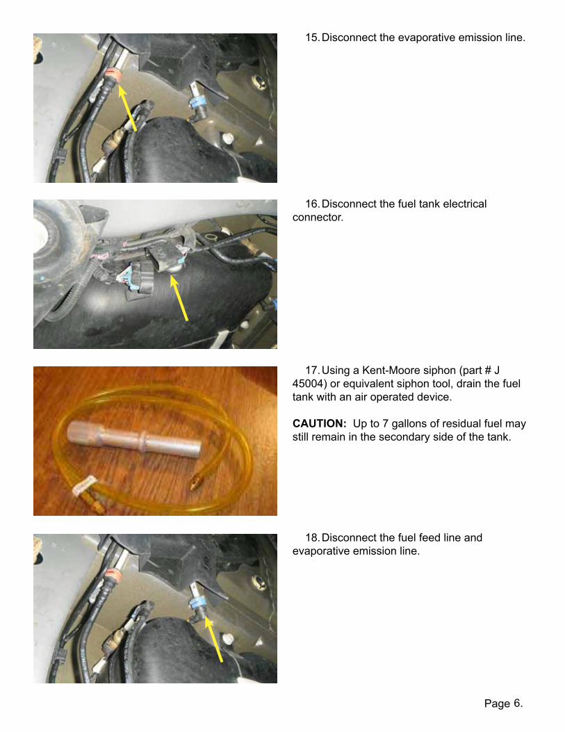
15. Disconnect the evaporative emission line.
16. Disconnect the fuel tank electrical connector.
17. Using a Kent-Moore siphon (part # J 45004) or equivalent siphon tool, drain the fuel tank with an air operated device. CAUTION: Up to 7 gallons of residual fuel may still remain in the secondary side of the tank.
18. Disconnect the fuel feed line and evaporative emission line.

Page 7.
19. With an assistant or a jack supporting the tank, remove the four (4) 15mm fuel tank support strap bolts.
20. Remove the tank from the vehicle and place it on a work bench or clear area. Use compressed air to clear of any debris from the top of the gas tank.
21. Disconnect the wiring connectors from the fuel pump and transfer pick-up modules.
22. Disconnect the fuel line from the primary fuel pump module.
Page 8.
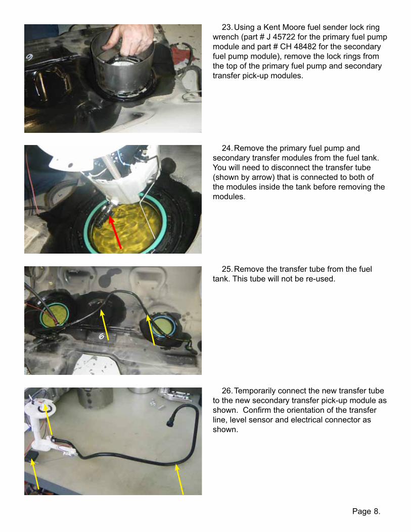
23. Using a Kent Moore fuel sender lock ring wrench (part # J 45722 for the primary fuel pump module and part # CH 48482 for the secondary fuel pump module), remove the lock rings from the top of the primary fuel pump and secondary transfer pick-up modules.
24. Remove the primary fuel pump and secondary transfer modules from the fuel tank. You will need to disconnect the transfer tube (shown by arrow) that is connected to both of the modules inside the tank before removing the modules.
25. Remove the transfer tube from the fuel tank. This tube will not be re-used.
26. Temporarily connect the new transfer tube to the new secondary transfer pick-up module as shown. Confirm the orientation of the transfer line, level sensor and electrical connector as shown.

Page 9.
27. Using the supplied Zip ties, secure the red and black primary float transfer wires to the transfer tube.
28. Place a tie at every elbow on the transfer tube. You should also have a tie about 2-3in from the fuel pump end. Cut the excess portion of the Zip tie that remains after securing the float transfer wires to the transfer tube.
29. Insert the primary module end (end with 180 degree bend) of the transfer tube into the transfer pick-up module side of the tank. Using a fish tape or coat hanger, guide the transfer tube up and over the hump inside the tank.
30. Disconnect the transfer tube from the secondary transfer pick-up module. You will need to re-connect it inside of the tank after the float has been maneuvered into place.
Page 10.
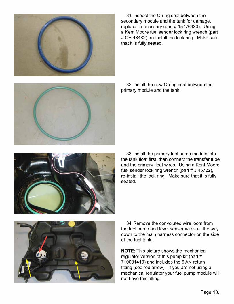
31. Inspect the O-ring seal between the secondary module and the tank for damage, replace if necessary (part # 15776433). Using a Kent Moore fuel sender lock ring wrench (part # CH 48482), re-install the lock ring. Make sure that it is fully seated.
32. Install the new O-ring seal between the primary module and the tank.
33. Install the primary fuel pump module into the tank float first, then connect the transfer tube and the primary float wires. Using a Kent Moore fuel sender lock ring wrench (part # J 45722), re-install the lock ring. Make sure that it is fully seated.
34. Remove the convoluted wire loom from the fuel pump and level sensor wires all the way down to the main harness connector on the side of the fuel tank. NOTE: This picture shows the mechanical regulator version of this pump kit (part # 710081410) and includes the 6 AN return fitting (see red arrow). If you are not using a mechanical regulator your fuel pump module will not have this fitting.

Page 11.
35. Cut the four (4) wires from the primary module connector on the passenger side of the tank as close to the connector as possible. The factory connector will not be re-used. Separate the two (2) larger gauge fuel pump wires from the two (2) smaller gauge level sensor wires.
36. Splice the pink wires of the LPE supplied fuel pump module connector (part # L760041410) to the larger gauge pink (black in early model year vehicles) wire that you cut in step 35. Cut the larger gauge grey (red in early model year vehicles) wire to length and splice it into the gray wires of the LPE connector. Strip the wires 3/8” down and crimp them into the connectors on the LPE provided harness using an insulated connector crimping tool. Set the heat shrink using a heat gun.
37. On the driver side of the vehicle, cut off the secondary module connector from the two (2) secondary level sensor wires (light blue and brown) as close to the connector as possible. The factory connector, as well as the looped wire populating the last two pin locations on the factory connector, will not be re-used. Using a crimping tool, crimp the new terminals (part # 54001800) onto the factory sensor harness wires (brown and light blue).
38. Install the secondary level sensor wires (light blue and brown) into the new 4-way connector with the primary extension wires (part # L760031410), which is already installed on the secondary module. Refer to table 2 on page 23 for proper connector pinouts.
To Pink (or black) wires ( - negative)
To Gray (or red) Wires ( + positive)
Page
Driver sidePassenger side
12.
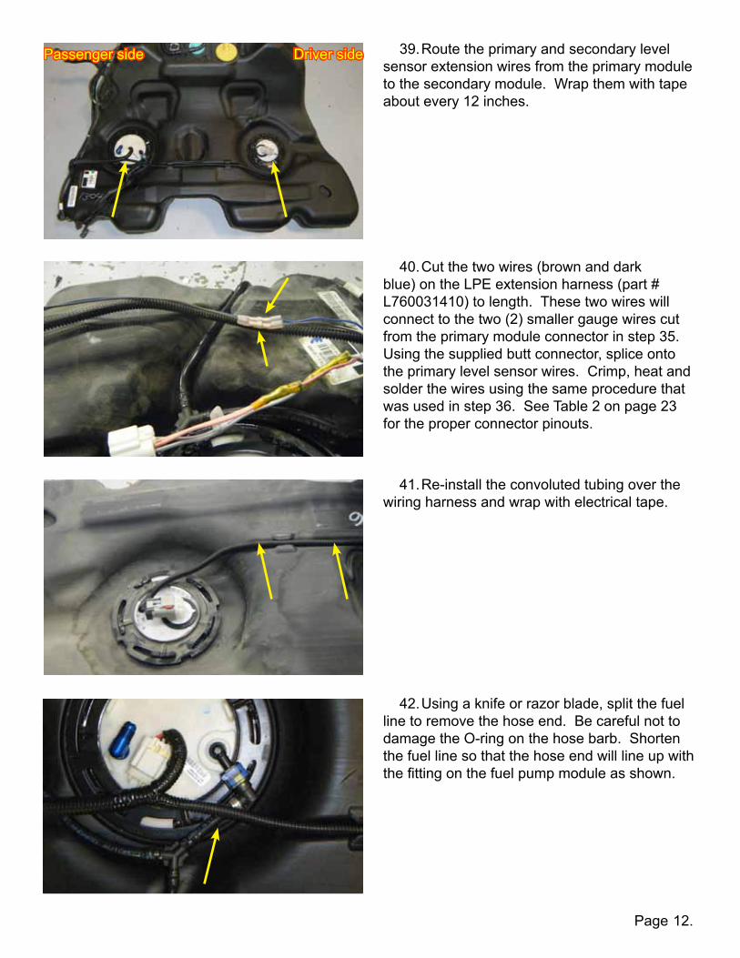
39. Route the primary and secondary level sensor extension wires from the primary module to the secondary module. Wrap them with tape about every 12 inches.
40. Cut the two wires (brown and dark blue) on the LPE extension harness (part # L760031410) to length. These two wires will connect to the two (2) smaller gauge wires cut from the primary module connector in step 35. Using the supplied butt connector, splice onto the primary level sensor wires. Crimp, heat and solder the wires using the same procedure that was used in step 36. See Table 2 on page 23 for the proper connector pinouts.
41. Re-install the convoluted tubing over the wiring harness and wrap with electrical tape.
42. Using a knife or razor blade, split the fuel line to remove the hose end. Be careful not to damage the O-ring on the hose barb. Shorten the fuel line so that the hose end will line up with the fitting on the fuel pump module as shown.

Page 13.
43. Slide the Oeticker clamp over the end of the fuel line. Re-install the hose end into the fuel line and secure with the Oeticker clamp.
44. Re-connect the wiring and the fuel line to the top of the primary and secondary modules. Make sure the red clip locking devices are secured.
45. If you are using a mechanical fuel pressure regulator, hook up the return line from the mechanical regulator to the blue fitting shown.
46. Install the fuel tank in the reverse order that it was removed. The subframe bolts are torqued to 74 ft-lbs and then turn them another 110 degrees clockwise.

Page
47. Remove the lower portion of the back seat by lifting up and tilting the seat out while pulling it toward the front of the vehicle.
48. Remove the top portion of the back seat by pulling the tab as indicated and laying the seats all the way forward.
49. Move the spring loaded retaining clip back while lifting the seat up slightly and removing the pin indicated from the bracket.
50. Remove the step panel from the passenger side of the vehicle by lifting from underneath the panel and popping the retaining clips out.
14.

Page
51. Remove the interior panel from the back seat on the passenger side of the vehicle by working your way from the front to the back, popping out the retaining clips.
52. With the interior panel removed, locate the fuel pump control module.
53. Pull the red retaining clip to the left as shown.
54. Lift the release lever toward the front of the vehicle as shown and remove the electrical connector from the fuel pump control module.
15.

Page
55. Using a 10 mm socket, remove the fuel pump control module nut and remove the control module by bending it toward the rear of the vehicle and pulling it out.
16.
56.IMPORTANT:UseFigure1andTable1onpages21and22forthepinninglocationsandwirecolors.Notethatsomepicturesshowthewiringharnessoutofthevehicleforeaseofviewing. IfyouareinstallinganLPEelectronicfuelpumpcontrolmodule,skipsteps56-63.Ifyouareinstallingamechanicalregulator,continueontostep56.
57.Mechanicalfuelpressureregulatorversioninstructions(steps56-63):In order to run a mechanical fuel pressure regulator you must disable the production fuel pump control module. Note that the fuel pump control module is on the CAN (controller area network) bus. Simply unplugging the module will leave this circuit open and cause diagnostic communication errors.
58. Splice the tan/black wires from pins 5 & 6 together.
NOTE:Figure1depictstheviewfromtheharnessside.
Page
59. Splice the tan wires from pins 17 & 18 together to by-pass the fuel pump control module.
60. You will then need to wire in a fuel pump relay. Remove the red/white wire from pin 1 and connect it to the terminal labeled 30 on the relay.
61. Remove the gray wire from pin 13 and connect it to the relay terminal labeled 87.
62. Remove the dark green/white wire from pin 20. This is a 12V fuel pump “on” command from the ECM and should be connected to the relay terminal 85.
17.

Page
64. Remove the black wire from pin 25 and the pink wire from pin 38 and splice them together.
65.LPEelectronicfuelpumpcontrolversion(steps64-70):Using a pin tool or pick, remove the white terminal retaining clips from the face of the electrical connectors on the stock Camaro connector and the LPE supplied connector.
66. Mark the tan and tan with black stripe wires (CAN Bus wires) in cavities 5, 6, 17 and 18 with a piece of masking tape or equivalent showing the numbered cavities in which they were removed. There are two (2) of each and they need to be marked so that they can be relocated correctly. WARNING:FlippingtheendsofthewiresorreinstallingthewiresintotheincorrectcavitieswillcauseacomunicationerrorbetweenthefuelpumpcontrolmoduleandtheECMtooccur.
63. Connect terminal 86 on the relay to a chassis ground (or remove the black wire from pin 25 on the fuel pump control module and connect terminal 86 to it).
18.
UseFigure1andTable1onpages21and22forthepinninglocationsandwirecolors. PleasenotethatFigure1depictstheviewfromtheharnessside.

Page
67. Using a pin tool or pick, remove the larger wires from cavities 1, 13, 25 and 38. You will need to replace the terminals on these four (4) wires with the larger terminals that are provided (part # 15476168).
68. Using a pin tool or pick, remove the remaining wires and install them into their correct locations in the LPE connector using Figure 1 and Table 1 on pages 21 and 22. The small stock terminals are compatible with the LPE fuel pump control module connector. Only the four (4) larger terminals need replaced.
69. Re-install the white terminal retaining clip on the face of the LPE connector.
70. Install the LPE fuel pump control module to the same mounting location as the stock controller. One bolt hole can be re-used while the other two must be screwed into place using the LPE provided self-tapping screws (part # TS-TEK106).
19.
NOTE:Figure1depictstheviewfromtheharnessside.
Page
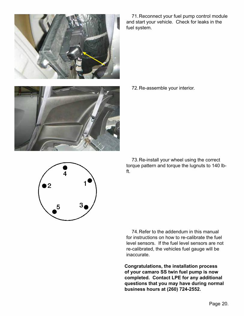
71. Reconnect your fuel pump control module and start your vehicle. Check for leaks in the fuel system.
20.
72. Re-assemble your interior.
73. Re-install your wheel using the correct torque pattern and torque the lugnuts to 140 lb-ft.
74. Refer to the addendum in this manual for instructions on how to re-calibrate the fuel level sensors. If the fuel level sensors are not re-calibrated, the vehicles fuel gauge will be inaccurate.
Congratulations,theinstallationprocessofyourcamaroSStwinfuelpumpisnowcompleted.ContactLPEforanyadditionalquestionsthatyoumayhaveduringnormalbusinesshoursat(260)724-2552.

Page 21.
12
34
56
78
910
1112
1314
1516
1718
1920
2122
2324
2526
2728
2930
31
3233
3435
3637
3839
4041
4243
4445
4647
SCA
LE:
SIZED
WG
. NO
.
AREV.
MA
TERIAL
FINISH
DO
NO
T SCA
LE DRA
WIN
GA
PPLICA
TION
USED O
NN
EXT ASSY
DIM
ENSIO
NS A
RE IN IN
CHES
TOLERA
NC
ES:FRA
CTIO
NA
LA
NG
ULAR: M
AC
H BEN
D
TWO
PLAC
E DEC
IMA
L 0.005*
THREE PLAC
E DEC
IMA
L 0.001*
*UNLESS STA
TED O
THERWISE
NA
ME
DA
TE
DRA
WN
CHEC
KED
ENG
APPR.
MFG
APPR.
Q.A
.
SHEET 1 OF 1
WEIG
HT:
CO
MM
ENTS:
REVISION
S
DESC
RIPTION
REV.D
ATE
APPRO
VED
THE INFO
RMA
TION
CO
NTA
INED
IN THIS
DRA
WIN
G IS THE SO
LE PROPERTY O
FLIN
GEN
FELTER PERFORM
AC
E ENG
INEERIN
G.
AN
Y REPROD
UCTIO
N IN
PART O
R AS A
WHO
LEW
ITHOUT THE W
RITTEN PERM
ISSION
OF
LING
ENFELTER PERFO
RMA
CE EN
GIN
EERING
IS PROHIBITED
.
PROPRIETA
RY AN
D CO
NFIDEN
TIAL
DW
G. N
AM
E
12
34
56
78
910
1112
13
1415
1617
1819
2021
2223
24
2526
2728
2930
3132
3334
3536
3738
SCA
LE:
SIZED
WG
. NO
.
AREV.
MA
TERIAL
FINISH
DO
NO
T SCA
LE DRA
WIN
GA
PPLICA
TION
USED O
NN
EXT ASSY
DIM
ENSIO
NS A
RE IN IN
CHES
TOLERA
NC
ES:FRA
CTIO
NA
LA
NG
ULAR: M
AC
H BEN
D
TWO
PLAC
E DEC
IMA
L 0.005*
THREE PLAC
E DEC
IMA
L 0.001*
*UNLESS STA
TED O
THERWISE
NA
ME
DA
TE
DRA
WN
CHEC
KED
ENG
APPR.
MFG
APPR.
Q.A
.
SHEET 1 OF 1
WEIG
HT:
CO
MM
ENTS:
REVISION
S
DESC
RIPTION
REV.D
ATE
APPRO
VED
THE INFO
RMA
TION
CO
NTA
INED
IN THIS
DRA
WIN
G IS THE SO
LE PROPERTY O
FLIN
GEN
FELTER PERFORM
AC
E ENG
INEERIN
G.
AN
Y REPROD
UCTIO
N IN
PART O
R AS A
WHO
LEW
ITHOUT THE W
RITTEN PERM
ISSION
OF
LING
ENFELTER PERFO
RMA
CE EN
GIN
EERING
IS PROHIBITED
.
PROPRIETA
RY AN
D CO
NFIDEN
TIAL
DW
G. N
AM
E
2010 Cam
aro SS
fuel pump control m
odule pin locations
LPE
fuel pump control m
odule pin locations
FIGURE1:Pinnum
bersontheLPEtwinfuelpum
pcontrolmoduleandfactory
Cam
aroSSfuelpumpcontrolm
odule.NOTE:Thisillustrationdepictstheview
fromtheharnessside.
Page 22.
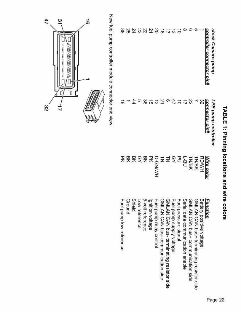
TA
BLE1:Pinninglocationsandw
irecolors
stock Cam
aro pump
LPE pum
p controller
controller connector pin# connector pin#
W
ire color
Function
1
32
R
D/W
H
B
attery positive voltage
5
7
TN
/BK
GM
LAN
CA
N bus+ term
inating resistor side
6
22
TN
/BK
GM
LAN
CA
N bus+ com
munication side
8
17
L-BU
S
erial data comm
unication enable
10
10
P
U
Fuel pressure signal
13
47
G
Y
Fuel pum
p supply voltage
17
6
TN
G
MLA
N C
AN
bus- terminating resistor side
18
21
TN
GM
LAN
CA
N bus- com
munication side
20
13
D-G
N/W
H
Fuel pum
p relay control
21
15
P
K
Ignition voltage
22
36
B
N
5-volt reference
23
5
G
Y
Low
reference
24
44
B
K
Shield
25
1
BK
G
round
38
16
P
K
Fuel pump low
reference
New
fuel pump controller m
odule connector end view:

Page 23.
TABLE2:Fuelpumpandlevelsensorwiring
2010Camarofuelpumpandlevelsensorassemblyconnectorendview Pin Wire Circuit Stock Function 1 GY (RD*) 120 Fuel Pump Supply Voltage 2 PK (BK*) 1580 Fuel Pump Low Reference 3 BN / WH 6281 Fuel Level Sensor Low Reference 4 D-BU (WH*) 1936 Primary Fuel Level Sensor Signal
LPEtwinpumpsystem,twinpumpmodule Pin Wire Circuit New Function 1 GY 120 Fuel Pump Supply Voltage 2 PK 1580 Fuel Pump Low Reference 3 PK 1580 Fuel Pump Low Reference 4 GY 120 Fuel Pump Supply Voltage
2010Camarosecondaryfuellevelsensorassemblyconnectorendview Pin Wire Circuit Stock Function 1 -- -- Not Used 2 -- -- Not Used 3 BN / WH 6281 Fuel Level Sensor Low Reference 4 L-BU (YE*) 1937 Secondary Fuel Level Sensor Signal
LPEtwinpumpsystem,fuellevelsensormodule,secondary Pin Wire Circuit New Function 1 BN 6281 Fuel Level Sensor Low Reference 2 D-BU 1936 Primary Fuel Level Sensor Signal 3 BN / WH 6281 Fuel Level Sensor Low Reference 4 L-BU 1937 Secondary Fuel Level Signal *Early production

Addendum
This addendum is provided to assist with the recalibration of a 2010-2013Camaro equipped with the Lingenfelter Performance Engineering (LPE)Camaro SS Twin Fuel Pump System (PN's: L710071410, L710081410).
After the installation of the LPE Camaro SS Twin Fuel Pump System, theEngine Control Module (ECM) must be re-programmed for the new fuellevel sensor calibration. This addendum will focus on re-calibrating the
vehicle through the use of the EFILive Tune software program. If thisprogram is not available to you, an EFILive AutoCal handheld device (PN:
EFIAUTOCAL) can be used to re-calibrate the vehicle.
Page 1.

Page 2.
1 Calibrating the Fuel Level Sensors Using EFILive
The following steps explain how to calibrate the Fuel Level Sensors using EFILive Tune Version 7.5.
1. Open the EFILive Tune V7.5 software program. This can be done by going to Start / All Programs / EFILive /
V7.5 / EFILive V7.5 Tune Tool, or by clicking on the EFILive V7.5 Tune Tool shortcut on the Desktop.
2. If you don't have a copy of your car's calibration, connect the EFILive V2 cable to your vehicle and your
computer. If you already have a copy of your vehicle's current calibration, proceed to step 4.
3. After connecting the EFILive V2 cable, read the current vehicle calibration to your computer.
Page 3.
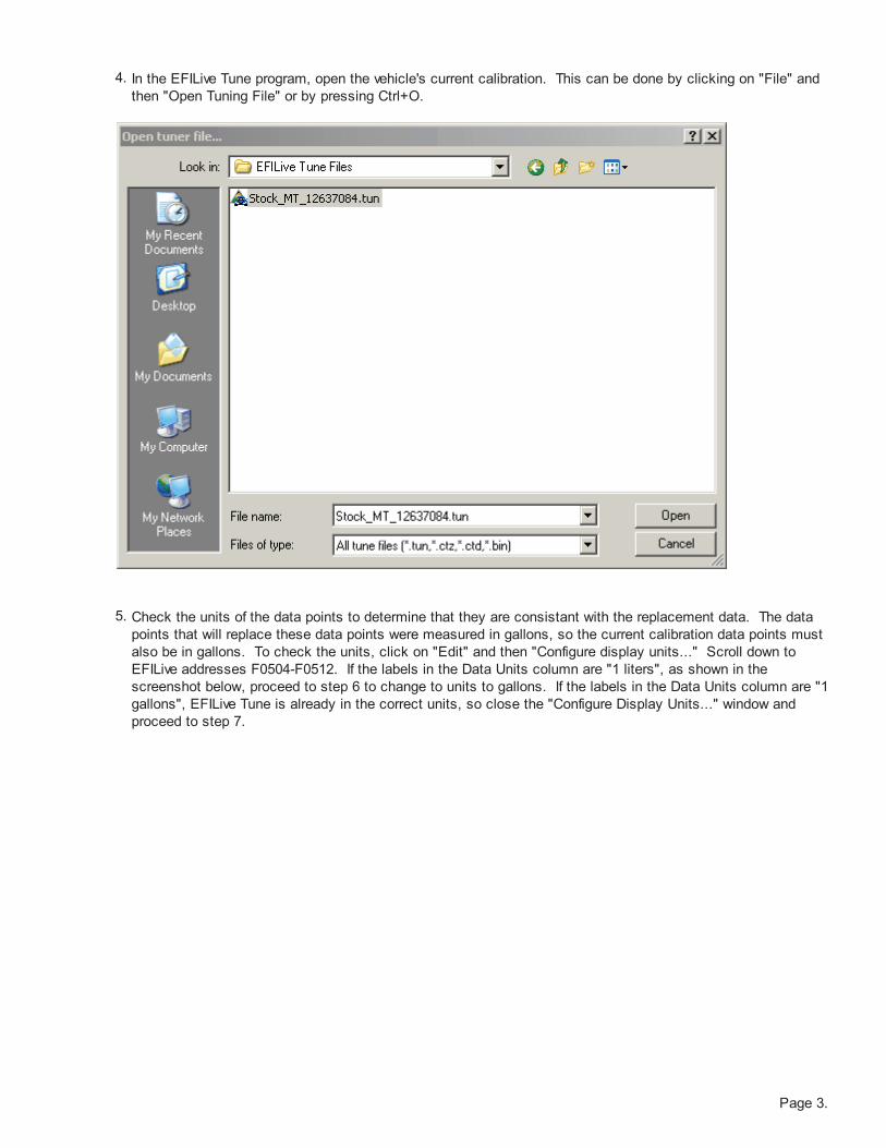
4. In the EFILive Tune program, open the vehicle's current calibration. This can be done by clicking on "File" and
then "Open Tuning File" or by pressing Ctrl+O.
5. Check the units of the data points to determine that they are consistant with the replacement data. The data
points that will replace these data points were measured in gallons, so the current calibration data points must
also be in gallons. To check the units, click on "Edit" and then "Configure display units..." Scroll down to
EFILive addresses F0504-F0512. If the labels in the Data Units column are "1 liters", as shown in the
screenshot below, proceed to step 6 to change to units to gallons. If the labels in the Data Units column are "1
gallons", EFILive Tune is already in the correct units, so close the "Configure Display Units..." window and
proceed to step 7.

Page 4.
6. Highlight EFILive addresses F0504-F0512 and click on the "Imperial" button. The units should now be "1
gallons", as shown in the screenshot below.

Page 5.
7. Below are the four (4) calibration tables that need to be changed, along with their respective EFILive address
(F05XX):
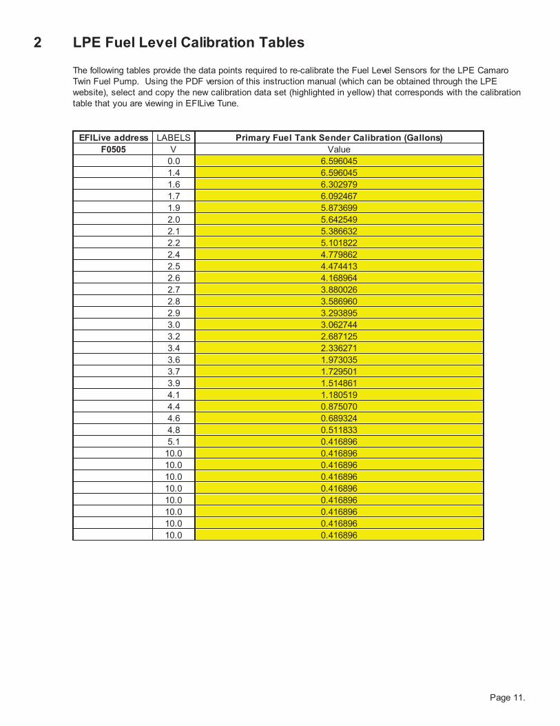
(F0505) Primary Fuel Tank Sender Calibration
(F0506) Primary Fuel Tank Sender Diagnostics Calibration
(F0511) Secondary Fuel Tank Sender Calibration
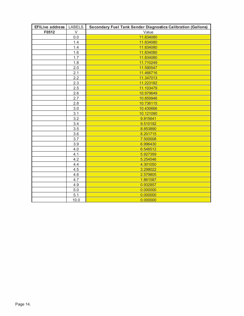
(F0512) Secondary Fuel Tank Sender Diagnostics Calibration
8. Locate the fuel tank calibrations in EFILive. These calibrations can be accessed through the "Calibrations" root
directory or by the search feature of the navigator.
a. To locate the calibrations through the "Calibrations" root directory, click on "Fuel System" and then "Fuel
Tank." All four of the calibrations appear as shown by the red arrows on the screenshot below. Double-click
on "Primary Fuel Tank Sender Calibration" and the calibration table will appear in the main window of the
EFILive Tune program.
b. To locate the calibrations though the search feature of the navigator, enter the EFILive address of the desired
calibration into the dialog box and click "Search." The calibration table will appear in the main window of the
EFILive Tune program.

Page 6.
9. If you located the fuel tank calibrations through the "Calibrations" root directory, double-click on one of the four
calibrations to open the calibration table in the main window. For these instructions, we will recalibrate the
Primary Fuel Tank Sender Calibration (F0505) first.

Page 7.
10.From the PDF version of this instruction manual (which can be obtained through the LPE website), select and
copy the new calibration data set (highlighted in yellow) that corresponds with the calibration table that you are
viewing in EFILive Tune. The new calibration data sets are available in the LPE Fuel Level Calibration Tables
section of these instructions.
NOTE: Make sure that the EFILive address of the data that you are copying from the spreadsheet
corresponds with the EFILive address of the data that you are replacing. Mismatching the EFILive
addresses will result in an incorrect calibration.

Page 8.
11.In the EFILive Tune program, select the entire table to be replaced. This can be done by clicking on the box in
the upper left corner of the table, as shown below by the red arrow.
12. Paste the new values from the spreadsheet into the respective fuel tank calibration table in the EFILive Tune
program. This can be done by using any of the three methods denoted by the bullet points below. These data
points can also be viewed in the LPE Fuel Level Calibration Tables section of these instructions
Hold and press Ctrl+V
Click the "Copy Data from Clipboard" or "Paste" button in the EFI Live Tune toolbar, as shown by the red arrow.
Right-click on the highlighted table in EFILive Tune and select "Paste." Move up the paste options until "Paste"
is selected , then click the "Paste" button.
13. Repeat steps 7-12 for the other three calibration tables (F0506, F0511, F0512).

Page 9.
14. Save your new calibration by clicking "File", and then "Save as".
NOTE: You MUST save the data before you can flash the the new calibration to the vehicle.

Page 10.
15. To flash the new fuel level calibration to the vehicle using the EFILive V2 cable, open the "flash" menu and
click on the "Program PCM calibrations" button. Because just the fuel level calibrations are being modified, a
full PCM operating system flash is not necessary.
Recalibration of the Fuel Level Sensors for the Camaro Twin Fuel Pump is now complete.
Page 11.
2 LPE Fuel Level Calibration Tables
The following tables provide the data points required to re-calibrate the Fuel Level Sensors for the LPE Camaro
Twin Fuel Pump. Using the PDF version of this instruction manual (which can be obtained through the LPE
website), select and copy the new calibration data set (highlighted in yellow) that corresponds with the calibration
table that you are viewing in EFILive Tune.
EFILive address LABELS
F0505 V
0.0
1.4
1.6
1.7
1.9
2.0
2.1
2.2
2.4
2.5
2.6
2.7
2.8
2.9
3.0
3.2
3.4
3.6
3.7
3.9
4.1
4.4
4.6
4.8
5.1
10.0
10.0
10.0
10.0
10.0
10.0
10.0
10.0
Primary Fuel Tank Sender Calibration (Gallons)
Value
6.596045
6.596045
6.302979
6.092467
5.873699
5.642549
5.386632
5.101822
4.779862
4.474413
4.168964
3.880026
3.586960
3.293895
3.062744
2.687125
2.336271
1.973035
1.729501
1.514861
1.180519
0.875070
0.689324
0.511833
0.416896
0.416896
0.416896
0.416896
0.416896
0.416896
0.416896
0.416896
0.416896

Page 12.
EFILive address LABELS
F0506 V
0.0
1.4
1.6
1.8
1.9
2.0
2.1
2.2
2.3
2.4
2.5
2.6
2.7
2.7
2.8
2.9
3.0
3.1
3.3
3.4
3.5
3.7
3.8
3.9
4.0
4.2
4.3
4.5
4.7
4.8
5.0
5.1
10.0
Primary Fuel Tank Sender Diagnostics Calibration (Gallons)
Value
6.736386
6.736386
6.736386
6.530002
6.331873
6.150254
5.952125
5.704464
5.448548
5.180248
4.887182
4.544584
4.123560
3.735557
3.425981
3.223724
3.021467
2.802700
2.579805
2.299122
2.001928
1.717118
1.523117
1.324988
1.159880
1.056688
0.949368
0.846176
0.742984
0.565493
0.000000
0.000000
0.000000

Page 13.
EFILive address LABELS
F0511 V
0.0
1.4
1.4
1.6
1.7
1.8
2.0
2.1
2.2
2.3
2.5
2.6
2.7
2.8
3.0
3.1
3.2
3.4
3.5
3.6
3.7
3.9
4.0
4.1
4.2
4.4
4.5
4.6
4.7
4.9
5.0
5.1
10.0
Secondary Fuel Tank Sender Calibration (Gallons)
Value
12.176678
12.176678
12.201444
12.201444
12.201444
12.201444
12.201444
12.028081
11.858846
11.685483
11.516248
11.342885
11.169522
11.000287
10.731988
10.467816
10.199516
9.935344
9.328574
8.717676
8.110906
7.272985
6.472214
5.696209
4.940842
4.210241
3.574577
2.910020
2.303250
1.461201
0.557238
0.000000
0.000000
Page 14.
EFILive address LABELS
F0512 V
0.0
1.4
1.4
1.6
1.7
1.8
2.0
2.1
2.2
2.3
2.5
2.6
2.7
2.8
3.0
3.1
3.2
3.4
3.5
3.6
3.7
3.9
4.0
4.1
4.2
4.4
4.5
4.6
4.7
4.9
5.0
5.1
10.0
Secondary Fuel Tank Sender Diagnostics Calibration (Gallons)
Value
11.834080
11.834080
11.834080
11.834080
11.834080
11.710249
11.590547
11.466716
11.347013
11.223182
11.103479
10.979649
10.859946
10.736115
10.430666
10.121090
9.815641
9.510192
8.853890
8.201715
7.500008
6.996430
6.546512
5.927359
5.254546
4.301050
3.298022
2.579805
1.861587
0.932857
0.000000
0.000000
0.000000

For additional product installation information and technical support, contactLPE or your LPE products distributor. you can also find technical support andusage discussions regarding this product and many other LPE products in ourinternet forums:
http://www.lingenfelter.com/LPEforumfiles
Lingenfelter Performance Engineering1557 Winchester Road
Decatur, IN 46733(260) 724-2552
(260) 724-8761 faxwww.lingenfelter.com
L710071410 L710081410 Camaro SS twin fuel pump installation v2.1.indd
Photo by SDW Photography
The LPE Camaro drag car pictured above is powered by a 427 CID LSX
engine equipped with a LS9 supercharger and two stages of nitrous. This
4200 lb vehicle currently produces 1250 rwhp. Equipped with a manual
transmission, this vehicle has achieved a best ET to date of 8.99 at 158 mph
and a best 60' of 1.304 seconds.