Embed Size (px)
Citation preview
INSTALLATION INSTRUCTIONS FOR
SPYKE MECHANICAL DISC BRAKE
NOTE: Be sure the rotation arrows point in the same direction as the rotation of the wheel.
INSTALLATION
SAFETY WARNINGS & INFORMATION
CAUTION - Cleanliness is a very important part of any maintenance of a TRP disc brake. If the pads or rotor become contaminated with oil, or if the system becomes contaminated with impurities, braking performance will be greatly impaired.
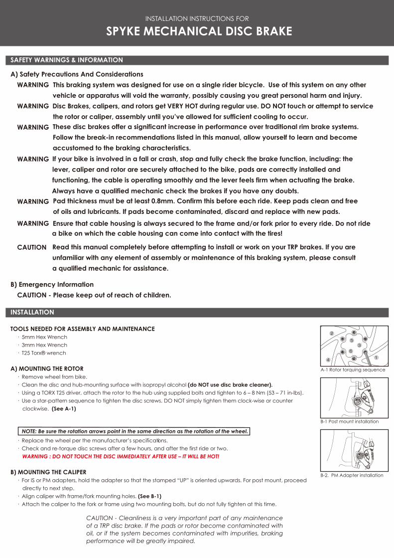
A-1 Rotor torquing sequence
2
4 1
35
6
B-1 Post mount installation
B-2. PM Adapter installation
A) Safety Precautions And ConsiderationsWARNING This braking system was designed for use on a single rider bicycle. Use of this system on any other
vehicle or apparatus will void the warranty, possibly causing you great personal harm and injury.WARNING Disc Brakes, calipers, and rotors get VERY HOT during regular use. DO NOT touch or attempt to service
the rotor or caliper, assembly until you’ve allowed for sufficient cooling to occur.WARNING
WARNING
Always have a qualified mechanic check the brakes if you have any doubts.WARNING
WARNING Ensure that cable housing is always secured to the frame and/or fork prior to every ride. Do not ride a bike on which the cable housing can come into contact with the tires!
CAUTION
B) Emergency InformationCAUTION - Please keep out of reach of children.
TOOLS NEEDED FOR ASSEMBLY AND MAINTENANCE· 5mm Hex Wrench· 3mm Hex Wrench· T25 Torx® wrench
A) MOUNTING THE ROTOR· Remove wheel from bike. · Clean the disc and hub-mounting surface with isopropyl alcohol (do NOT use disc brake cleaner).· Using a TORX T25 driver, attach the rotor to the hub using supplied bolts and tighten to 6 – 8 Nm (53 – 71 in-lbs). · Use a star-pattern sequence to tighten the disc screws. DO NOT simply tighten them clock-wise or counter
clockwise. (See A-1)
· Replace the wheel per the manufacturer’s specifications. · Check and re-torque disc screws after a few hours, and after the first ride or two.
WARNING : DO NOT TOUCH THE DISC IMMEDIATELY AFTER USE – IT WILL BE HOT!
B) MOUNTING THE CALIPER· For IS or PM adapters, hold the adapter so that the stamped “UP” is oriented upwards. For post mount, proceed
directly to next step.· Align caliper with frame/fork mounting holes. (See B-1) · Attach the caliper to the fork or frame using two mounting bolts, but do not fully tighten at this time.
These disc brakes offer a significant increase in performance over traditional rim brake systems. Follow the break-in recommendations listed in this manual, allow yourself to learn and become accustomed to the braking characteristics. If your bike is involved in a fall or crash, stop and fully check the brake function, including: the lever, caliper and rotor are securely attached to the bike, pads are correctly installed and functioning, the cable is operating smoothly and the lever feels firm when actuating the brake.
Pad thickness must be at least 0.8mm. Confirm this before each ride. Keep pads clean and free of oils and lubricants. If pads become contaminated, discard and replace with new pads.
Read this manual completely before attempting to install or work on your TRP brakes. If you are unfamiliar with any element of assembly or maintenance of this braking system, please consult a qualified mechanic for assistance.
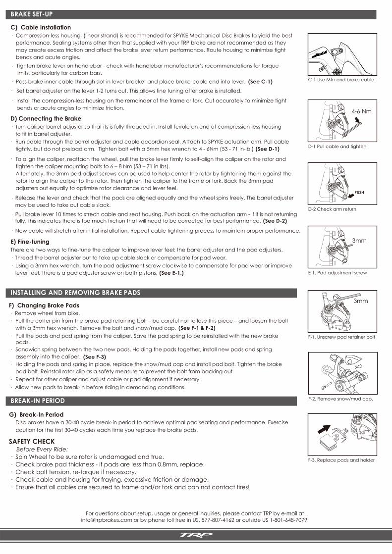
C-1 Use Mtn-end brake cable.
For questions about setup, usage or general inquiries, please contact TRP by e-mail at [email protected] or by phone toll free in US, 877-807-4162 or outside US 1-801-648-7079.
INSTALLING AND REMOVING BRAKE PADS
BREAK-IN PERIOD
BRAKE SET-UP
F) Changing Brake Pads· Remove wheel from bike.
Pull the cotter pin from the brake pad retaining bolt – be careful not to lose this piece – and loosen the bolt with a 3mm hex wrench. Remove the bolt and snow/mud cap. (See F-1 & F-2)
(See F-3)
Pull the pads and pad spring from the caliper. Save the pad spring to be reinstalled with the new brake pads. Sandwich spring between the two new pads. Holding the pads together, install new pads and spring assembly into the caliper. Holding the pads and spring in place, replace the snow/mud cap and install pad bolt. Tighten the brake pad bolt. Reinstall rotor clip as a safety measure to prevent the bolt from backing out. Repeat for other caliper and adjust cable or pad alignment if necessary.Allow new pads to break-in before riding in demanding conditions.
G) Break-In PeriodDisc brakes have a 30-40 cycle break-in period to achieve optimal pad seating and performance. Exercise caution for the first 30-40 cycles each time you replace the brake pads.
SAFETY CHECK Before Every Ride:· Spin Wheel to be sure rotor is undamaged and true.· Check brake pad thickness - if pads are less than 0.8mm, replace.· Check bolt tension, re-torque if necessary.· Check cable and housing for fraying, excessive friction or damage.· Ensure that all cables are secured to frame and/or fork and can not contact tires!
C) Cable Installation· Compression-less housing, (linear strand) is recommended for SPYKE Mechanical Disc Brakes to yield the best
performance. Sealing systems other than that supplied with your TRP brake are not recommended as they may create excess friction and affect the brake lever return performance. Route housing to minimize tight bends and acute angles.
·
·
Pass brake inner cable through slot in lever bracket and place brake-c
Tighten brake lever on handlebar - check with handlebar manufacturer’s recommendations for torque limits, particularly for carbon bars.
able end into lever.
Set barrel adjuster on the lever 1-2 turns out. This allows fine tuning after brake is installed.
·
(See C-1)
· Install the compression-less housing on the remainder of the frame or fork. Cut accurately to minimize tight bends or acute angles to minimize friction.
D) Connecting the Brake · Turn caliper barrel adjuster so that its is fully threaded in. Install ferrule on end of compression-less housing
to fit in barrel adjuster.
Run cable through the barrel adjuster and cable accordion seal. Attach to SPYKE actuation arm. Pull cable tightly, but do not preload arm. Tighten bolt with a 5mm hex wrench to 4 - 6Nm (53 - 71 in-lb.) (See D-1)
·
·
To align the caliper, reattach the wheel, pull the brake lever firmly to self-align the caliper on the rotor and tighten the caliper mounting bolts to 6 – 8 Nm (53 – 71 in lbs). Alternately, the 3mm pad adjust screws can be used to help center the rotor by tightening them against the rotor to align the caliper to the rotor. Then tighten the caliper to the frame or fork. Back the 3mm pad adjusters out equally to optimize rotor clearance and lever feel.
· Release the lever and check that the pads are aligned equally and the wheel spins freely. The barrel adjuster may be used to take out cable slack.
· Pull brake lever 10 times to strech cable and seat housing. Push back on the actuation arm - if it is not returning fully, this indicates there is too much friction that will need to be corrected for best performance.
(See D-2)
· New cable will stretch after initial installation. Repeat cable tightening process to maintain proper performance.
E) Fine-tuningThere are two ways to fine-tune the caliper to improve lever feel: the barrel adjuster and the pad adjusters.· Thread the barrel adjuster out to take up cable slack or compensate for pad wear. · Using a 3mm hex wrench, turn the pad adjustment screw clockwise to compensate for pad wear or improve
lever feel. There is a pad adjuster screw on both pistons.
(See E-1.)
PUSH
D-1 Pull cable and tighten.
4-6 Nm
D-2 Check arm return
E-1. Pad adjustment screw
3mm
F-1. Unscrew pad retainer bolt
3mm
F-3. Replace pads and holder
F-2. Remove snow/mud cap.
·
·
·
·
· ·