Embed Size (px)
Citation preview
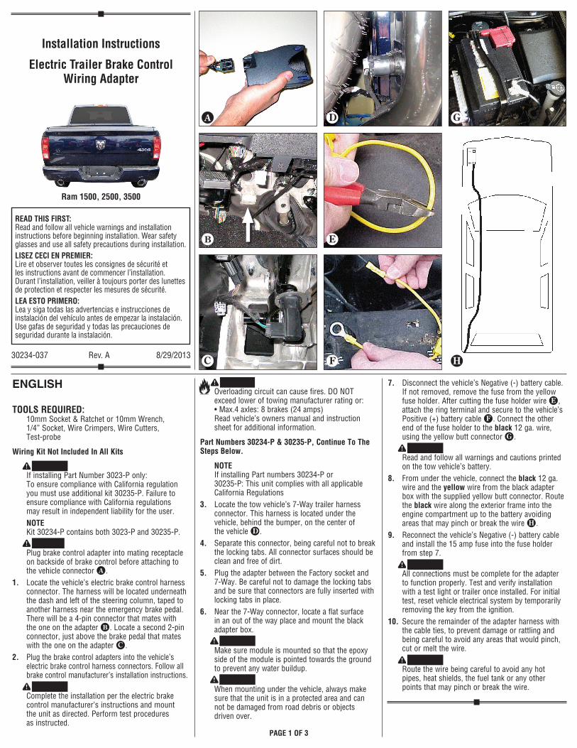
7. Disconnect the vehicle’s Negative (-) battery cable. If not removed, remove the fuse from the yellow fuse holder. After cutting the fuse holder wire h, attach the ring terminal and secure to the vehicle’s Positive (+) battery cable i. Connect the other end of the fuse holder to the black 12 ga. wire, using the yellow butt connector j.
WARNING Read and follow all warnings and cautions printed on the tow vehicle’s battery.
8. From under the vehicle, connect the black 12 ga. wire and the yellow wire from the black adapter box with the supplied yellow butt connector. Route the black wire along the exterior frame into the engine compartment up to the battery avoiding areas that may pinch or break the wire k.
9. Reconnect the vehicle’s Negative (-) battery cable and install the 15 amp fuse into the fuse holder from step 7.
WARNING All connections must be complete for the adapter to function properly. Test and verify installation with a test light or trailer once installed. For initial test, reset vehicle electrical system by temporarily removing the key from the ignition.
10. Secure the remainder of the adapter harness with the cable ties, to prevent damage or rattling and being careful to avoid any areas that would pinch, cut or melt the wire.
WARNING Route the wire being careful to avoid any hot pipes, heat shields, the fuel tank or any other points that may pinch or break the wire.
ENGLISH
TOOLS REQUIRED: 10mm Socket & Ratchet or 10mm Wrench, 1/4” Socket, Wire Crimpers, Wire Cutters, Test-probe
Wiring Kit Not Included In All Kits
WARNING If installing Part Number 3023-P only: To ensure compliance with California regulation you must use additional kit 30235-P. Failure to ensure compliance with California regulations may result in independent liability for the user.
NOTE Kit 30234-P contains both 3023-P and 30235-P.
CAUTION Plug brake control adapter into mating receptacle on backside of brake control before attaching to the vehicle connector d.
1. Locate the vehicle’s electric brake control harness connector. The harness will be located underneath the dash and left of the steering column, taped to another harness near the emergency brake pedal. There will be a 4-pin connector that mates with the one on the adapter e. Locate a second 2-pin connector, just above the brake pedal that mates with the one on the adapter f.
2. Plug the brake control adapters into the vehicle’s electric brake control harness connectors. Follow all brake control manufacturer’s installation instructions.
WARNING Complete the installation per the electric brake control manufacturer’s instructions and mount the unit as directed. Perform test procedures as instructed.
WARNING Overloading circuit can cause fires. DO NOT exceed lower of towing manufacturer rating or: • Max.4 axles: 8 brakes (24 amps) Read vehicle’s owners manual and instruction sheet for additional information.
Part Numbers 30234-P & 30235-P, Continue To The Steps Below.
NOTE If installing Part numbers 30234-P or 30235-P: This unit complies with all applicable California Regulations
3. Locate the tow vehicle’s 7-Way trailer harness connector. This harness is located under the vehicle, behind the bumper, on the center of the vehicle g.
4. Separate this connector, being careful not to break the locking tabs. All connector surfaces should be clean and free of dirt.
5. Plug the adapter between the Factory socket and 7-Way. Be careful not to damage the locking tabs and be sure that connectors are fully inserted with locking tabs in place.
6. Near the 7-Way connector, locate a flat surface in an out of the way place and mount the black adapter box.
WARNING Make sure module is mounted so that the epoxy side of the module is pointed towards the ground to prevent any water buildup.
WARNING When mounting under the vehicle, always make sure that the unit is in a protected area and can not be damaged from road debris or objects driven over.
READ THIS FIRST: Read and follow all vehicle warnings and installation instructions before beginning installation. Wear safety glasses and use all safety precautions during installation.LISEZ CECI EN PREMIER: Lire et observer toutes les consignes de sécurité et les instructions avant de commencer l’installation. Durant l’installation, veiller à toujours porter des lunettes de protection et respecter les mesures de sécurité.LEA ESTO PRIMERO: Lea y siga todas las advertencias e instrucciones de instalación del vehículo antes de empezar la instalación. Use gafas de seguridad y todas las precauciones de seguridad durante la instalación.
30234-037 Rev. A 8/29/2013
Ram 1500, 2500, 3500
Installation Instructions
Electric Trailer Brake Control Wiring Adapter
d
k
he
f i
jg
PAGE 1 OF 3

FraNçaIS
OUTILS REQUIS: Socket 10mm Ratchet & 10mm ou clé, 1/4” femelle, Sertisseurs, Coupe-fils, Sonde de vérification
La trousse de câblage n’est pas comprise dans toutes les nécessaires.
AVERTISSEMENT Uniquement dans le cas de l’installation du numéro de pièce 3023-P : Afin d’assurer la conformité avec le règlement de la Californie, vous devez utiliser une trousse supplémentaire 30235-P. La non-observation de la conformité avec le règlement de la Californie peut entrainer la responsabilité indépendante de l’utilisateur.
REMARQUE La trousse 30234-P contient 3023-P et 30235-P.
ATTENTION Brancher l’adaptateur de commande de frein dans le réceptacle homologue situé au dos de la commande de frein, avant de le raccorder au connecteur du véhicule d.
1. Repérer le connecteur du faisceau de fils de la commande de frein du véhicule. Le faisceau est situé sous le tableau de bord, à gauche de la colonne de direction, et il est fixé à un autre faisceau avec du ruban adhésif à proximité de la pédale de frein. Un connecteur à 4 broches qui correspond à celui del’adaptateur s’y trouve aussi e. Repérer un deuxième connecteur à 2 broches qui correspond à celui sur l’adaptateur, juste au-dessus de la pédale de frein f.
2. Brancher l’adaptateur de la commande de frein dans le connecteur du faisceau de fils de la commande de frein électrique du véhicule. Suivez toutes les directives d’installation du fabricant de la commande de frein.
AVERTISSEMENT Terminez l’installation en suivant les instructions du fabricant des freins électriques de commande et de monter l’appareil selon les instructions. Effectuer les tests en suivant les instructions.
AVERTISSEMENT Un circuit surchargé peut occasionner des incendies. NE DÉPASSEZ JAMAIS la valeur la plus basse indiquée par le fabricant de remorquage, ou: • Max. 4 ESSIEUX: 8 FREINS (24 ampères) Consultez le manuel du propriétaire et la feuille d’instructions du véhicule pour de plus amples informations.
Pour les numéros de pièce 30234-P et 30235-P, continuer avec les étapes ci-dessous.
REMARQUE Dans le cas de l’installation du numéro de pièce 30234-P ou 30235-P : Cet appareil est conforme à tous les règlements applicables de la Californie
3. Repérer le connecteur de faisceau de câbles de remorque à 7 voies du véhicule. Ce faisceau de câbles se trouve au centre et sous le véhicule, derrière le parechoc g.
4. Débrancher ce connecteur, en veillant à ne pas briser les pattes de verrouillage. Toutes les surfaces de contact des connecteurs doivent être propres et dépourvues de saleté.
5. Brancher l’adaptateur entre la prise d’usine et le connecteur à 7 voies. Prendre soin de ne pas endommager les pattes de verrouillage, s’assurer qu’elles sont verrouillées et que les connecteurs sont entièrement insérés.
6. À proximité du connecteur à 7 voies, repérer une surface plate, depuis et vers l’emplacement, et monter la boîte d’adaptateur noire.
AVERTISSEMENT Assurez-vous que le module est monté de manière à ce que le côté époxy du module soit pointé vers le sol pour éviter des accumulations d’eau.
AVERTISSEMENT Pour le montage sous le véhicule, toujours s’assurer que l’appareil se trouve dans un endroit protégé et qu’il ne peut être endommagé par des débris de la route ou d’autres objets sur lesquelles on pourrait passer.
7. Débrancher le câble de la borne négative (-) de la batterie du véhicule. Si ce n’est déjà fait, enlever le fusible du porte-fusible jaune. Après avoir coupé le fil du porte-fusible h, attacher la cosse à anneau et la fixer au câble de la borne positive (+) de la batterie du véhicule i. À l’aide du raccord jaune, attacher l’autre extrémité du porte-fusible au fil noir de calibre 12 j.
AVERTISSEMENT Lire et observer tous les avertissements et toutes les mises en garde concernant la batterie du véhicule à laquelle est installée la remorque.
8. Depuis le dessous du véhicule, brancher le fil noir de 12 ga et le fil jaune de la boîte d’adaptateur noire avec le raccord jaune fourni. Acheminer le fil noir le long du châssis extérieur dans le comparti-ment moteur jusqu’à la batterie en évitant les zones qui pourraient pincer ou rompre le fil k.
9. Rebrancher le câble de la borne négative (-) de la batterie du véhicule et placer le fusible de 15 ampères dans le porte-fusible mentionné à l’étape 7.
AVERTISSEMENT Pour que l’adaptateur fonctionne correctement, tous les raccords doivent être réalisés correctement. Tester et vérifier l’installation à l’aide d’une lampe témoin ou de la remorque, une fois qu’elle est installée. Pour le test initial, réinitialiser le système électrique du véhicule en retirant temporairement la clé du commutateur d’allumage.
10. Attacher l’excédent de faisceau de câbles d’adaptateur à l’aide d’attaches afin d’éviter des dommages ou des cliquetis; on doit s’assurer d’éviter toute zone qui pourrait pincer, couper ou faire fondre le fil.
AVERTISSEMENT Prendre soin d’éviter les tuyaux chauds, les écrans thermiques, le réservoir de carburant ou tout autre endroit susceptible de coincer ou endommager les fils.
PAGE 2 OF 3
© 2013 Cequent Performance Products, Inc.
ESpaÑoL
HERRAMIENTAS NECESSARIAS: Socket 10mm y 10mm o llave de carraca, 1/4” socket, Plegadores de cable, Cortadores de cable, Terminal de prueba
El kit de cables no se incluye en todos los kits.
ADVERTENCIA Si está instalando el número de parte 3023-P únicamente: Para verificar cumplimiento con la norma de California, debe usar el kit adicional 30235-P. No verificar el cumplimiento con las regulaciones de California podría resultar en responsabilidad civil independiente para el usuario.
NOTA El kit 30234-P contiene tanto el 3023-P como el 30235-P.
ATENCIÓN Conecte el adaptador de control del freno dentro del receptáculo correspondiente en la parte posterior del control del freno antes de instalarlo al conector del vehículo.
1. Localice el conector del arnés del control del freno eléctrico del vehículo. El arnés estará localizado debajo del tablero y a la izquierda de la columna de dirección, unido a otro arnés cerca del pedal del freno de emergencia. Habrá un conector de 4 patas quecorresponde con el que hay en el adaptador e. Localice un segundo conector de 2 patas, justo por encima del pedal del freno que coincida con el del adaptador f.
2. Conecte el adaptador del control del freno en el conector del arnés del control del freno eléctrico del vehículo. Siga todas las instrucciones de instalación del fabricante del control del freno.
ADVERTENCIA Complete la instalación según las instrucciones del fabricante del control del freno y montar la unidad como se indica. Lleve a cabo los procedimientos de prueba según las instrucciones.
ADVERTENCIA La sobrecarga del circuito puede ocasionar incendios. NO exceda la calificación de remolque más baja indicada por el fabricante o: • Máx. 4 EJES: 8 FRENOS (24 amperios) Lea el manual del propietario y la hoja de instruc-ciones del vehículo para información adicional.
Números de partes 30234-P y 30235-P, continúe con las pasos siguientes.
NOTA Si está instalando números de parte 30234-P o 30235-P: Esta unidad cumple con todas las regulaciones correspondientes de California
3. Localice el conector de arnés del remolque de 7 vías del vehículo de remolque. Este arnés se encuentra debajo del vehículo, detrás del parachoques, en el centro del vehículo g.
4. Separe este conector, con cuidado de no romper las pestañas de bloqueo. Todas las superficies del conector deben estar limpias y libres de suciedad.
5. Conecte el adaptador entre el acople de fábrica y el conector de 7 vías. Tenga cuidado de no dañar las lengüetas de bloqueo y cerciórese de que los conectores estén completamente insertados con las lengüetas de bloqueo en su lugar.
6. Cerca del conector de 7 vías, localice una superficie plana en un lugar que no estorbe e instale la caja adaptadora negra.
ADVERTENCIA Verifique que el módulo esté instalado de manera que el lado epóxico del módulo esté orientado hacia el piso para evitar la acumulación de agua.
ADVERTENCIA Al instalar debajo del vehículo, siempre verifique que la unidad esté en un área protegida y no se dañe con la suciedad de la calle u objetos encima de los cuales se ruede.
7. Desconecte el cable negativo (-) de la batería del vehículo. Si no se ha retirado, retire el fusible del portador de fusibles amarillo. Después de cortar el alambre del portador de fusibles h, una el terminal de anillo y asegúrelo al cable positivo (+) de la batería del vehículo i. Conecte el otro extremo del portador de fusibles al alambre negro de 12 ga. usando el conector de cabeza amarillo j.
ADVERTENCIA Lea y siga todas las advertencias y precauciones impresas en la batería del vehículo de remolque.
8. Desde la parte inferior del vehículo, conecte el cable negro de calibre 12 y el cable amarillo desde la caja adaptadora negra con el conector de tope amarillo que se suministra. Dirija el cable negro a lo largo del bastidor exterior dentro del compartimiento del motor hasta la batería evitando las áreas que podrían pellizcar o romper el cable k.
9. Vuelva a conectar el cable negativo (-) de la batería e instale el fusible de 15 amperios en el portador de fusibles del paso 7.
ADVERTENCIA Todas las conexiones deben estar completas para que el adaptador funcione correctamente. Revise y verifique la instalación con una luz de prueba o el remolque una vez se instale. Para la prueba inicial, reinicialice el sistema eléctrico del vehículo al retirar temporalmente la llave de la ignición.
10. Asegure el resto del arnés del adaptador con los amarres de cables, para evitar el daño o el traqueteo y con cuidado de evitar cualquier área que pudiera pellizcar, cortar o derretir el cable.
ADVERTENCIA Dirija el cable con cuidado de evitar cualquier tubería caliente, protectores de calor, el tanque de combustible o cualquier otro punto que podría pellizcar o romper el cable.
PAGE 3 OF 3