Embed Size (px)
Citation preview
Code No. 0816701Rev. 0a (02/08)
INSTALLATION INSTRUCTIONS FOR SENSOR ACTIVATEDBATTERY POWERED FLUSHOMETER
LIMITED WARRANTYSloan Valve Company warrants its Sloan Optima Plus Flushometers to be made of first class materials, free from defects of material or workmanship under normal use and to perform theservice for which they are intended in a thoroughly reliable and efficient manner when properly installed and serviced, for a period of three years (1 year for special finishes) from date ofpurchase. During this period, Sloan Valve Company will, at its option, repair or replace any part or parts which prove to be thus defective if returned to Sloan Valve Company, at customer'scost, and this shall be the sole remedy available under this warranty. No claims will be allowed for labor, transportation or other incidental costs. This warranty extends only to persons ororganizations who purchase Sloan Valve Company's products directly from Sloan Valve Company for purpose of resale. This warranty does not cover the life of the batteries.THERE ARE NO WARRANTIES WHICH EXTEND BEYOND THE DESCRIPTION ON THE FACE HEREOF. IN NO EVENT IS SLOAN VALVE COMPANY RESPONSIBLE FOR ANYCONSEQUENTIAL DAMAGES OF ANY MEASURE WHATSOEVER.
PRIOR TO INSTALLING THE SLOAN OPTIMA PLUSFLUSHOMETERPrior to installing the Sloan Optima Plus Flushometer, install the items listedbelow as illustrated in the Rough-in Diagram. (New installations only.)• Closet or Urinal fixture• Drain line• Water supply line
Important:• INSTALL ALL PLUMBING IN ACCORDANCE WITH APPLICABLE CODES
AND REGULATIONS.• WATER SUPPLY LINES MUST BE SIZED TO PROVIDE AN ADEQUATE
VOLUME OF WATER FOR EACH FIXTURE.• WHEN INSTALLING A FLUSHOMETER, IT IS IMPORTANT THAT THE FLUSH
MODEL MATCHES THE REQUIREMENTS OF THE PLUMBING FIXTURE.• FLUSH ALL WATER LINES PRIOR TO MAKING CONNECTIONS.
The Sloan Optima Plus is designed to operate with 15 to 100 PSI (104 to689 kPa) of water pressure. THE MINIMUM PRESSURE REQUIRED TO THEVALVE IS DETERMINED BY THE TYPE OF FIXTURE SELECTED. Consultfixture manufacturer for pressure requirements.Most Low Consumption water closets (1.6 gallon/6.0 liter) require aminimum flowing pressure of 25 psi (172 kPa).
TOOLS REQUIRED FOR INSTALLATION• Slotted screwdriver to adjust control stop.• Sloan A-50 Super-Wrench™, Sloan A-109 Plier Wrench or smooth jawed
spud wrench for couplings.• Trimpot adjustment screwdriver (supplied) to adjust range, if necessary.• Strap wrench (supplied) to install Optima Plus to valve body.• 7/64" hex wrench (supplied) to secure Optima Plus cover to base plate.
Optima Plus Urinal Models can be furnished for the following:0.5 gpf/1.9 Lpf For Wash Down Urinals1.0 gpf/3.8 Lpf For Low Consumption Urinals1.5 gpf/5.7 Lpf For older Siphon Jet Urinals3.5 gpf/13.2 Lpf For older Blow Out Urinals
Made in the U.S.A.
ExposedCloset Flushometer
1-1/2" Top SpudModel 8110/8111
Model 8113Model 8115Model 8116
ExposedUrinal Flushometer
1-1/4" Top SpudModel 8180
3/4" Top SpudModel 8186
Optima Plus Water Closet Models can be furnished for the following:1.6 gpf/6.0 Lpf For Low Consumption Bowls2.4 gpf/9.0 Lpf For 9 Liter European Water Closets3.5 gpf/13.2 Lpf For older Water Closets
ExposedCloset Flushometer1-1/2" Back Inlet
Squat ToiletModel 8137
2
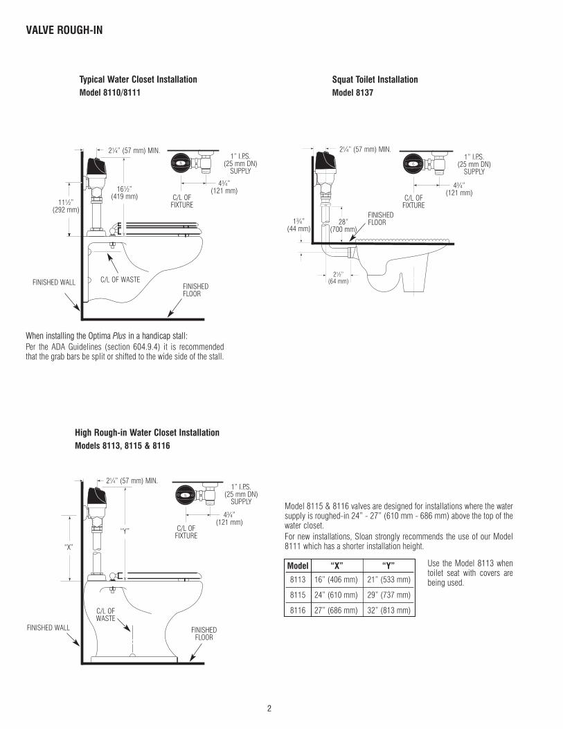
VALVE ROUGH-IN
Typical Water Closet InstallationModel 8110/8111
When installing the Optima Plus in a handicap stall:Per the ADA Guidelines (section 604.9.4) it is recommendedthat the grab bars be split or shifted to the wide side of the stall.
2¼” (57 mm) MIN.
16½” (419 mm)
C/L OF WASTEFINISHEDFLOOR
C/L OFFIXTURE
1” I.P.S.(25 mm DN)
SUPPLY
4¾”(121 mm)
2¼” (57 mm) MIN.
“Y”
C/L OFWASTE
FINISHED WALL FINISHEDFLOOR
C/L OFFIXTURE
1” I.P.S.(25 mm DN)
SUPPLY
4¾”(121 mm)
High Rough-in Water Closet InstallationModels 8113, 8115 & 8116
“X”
Model 8115 & 8116 valves are designed for installations where the watersupply is roughed-in 24” - 27” (610 mm - 686 mm) above the top of thewater closet.For new installations, Sloan strongly recommends the use of our Model8111 which has a shorter installation height.
Model “X” “Y”
8113 16” (406 mm) 21” (533 mm)
8115 24” (610 mm) 29” (737 mm)
8116 27” (686 mm) 32” (813 mm)
Use the Model 8113 whentoilet seat with covers arebeing used.
11½”(292 mm)
FINISHED WALL
Squat Toilet InstallationModel 8137
2¼” (57 mm) MIN.
C/L OFFIXTURE
1” I.P.S.(25 mm DN)
SUPPLY
4¾”(121 mm)
FINISHEDFLOOR28”
(700 mm)1¾”
(44 mm)
2½”(64 mm)
3
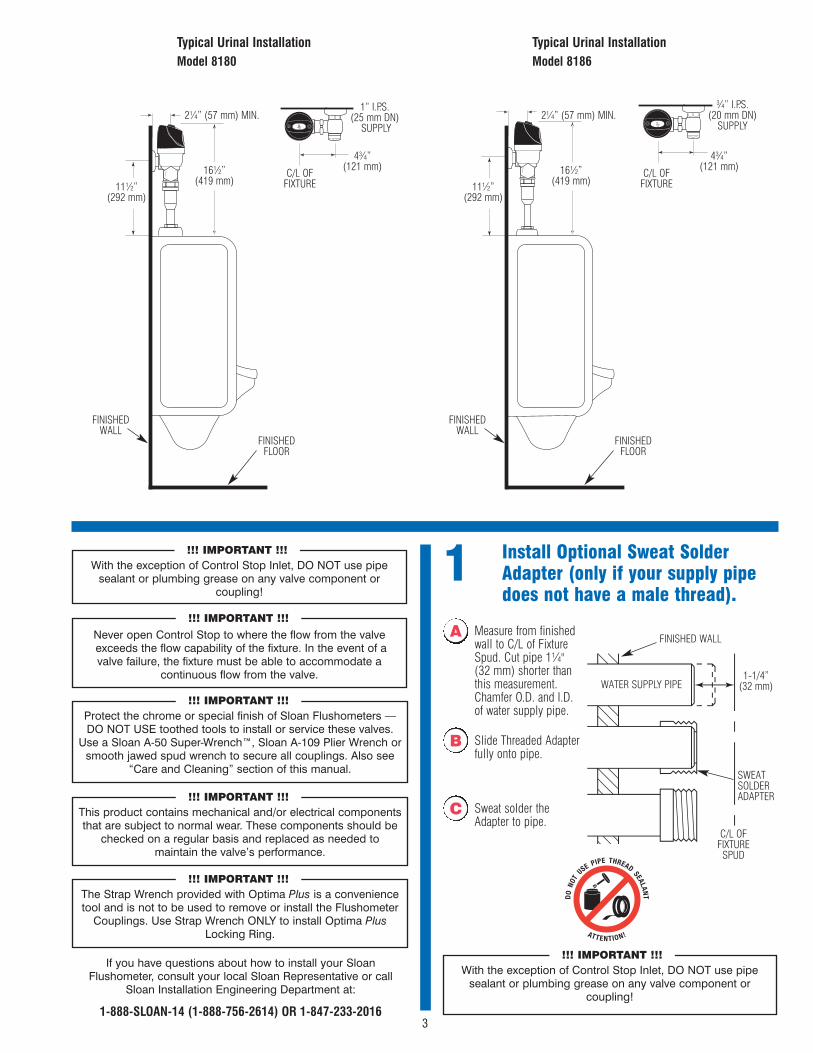
1 Install Optional Sweat SolderAdapter (only if your supply pipedoes not have a male thread).
With the exception of Control Stop Inlet, DO NOT use pipesealant or plumbing grease on any valve component or
coupling!
!!! IMPORTANT !!!
Protect the chrome or special finish of Sloan Flushometers —DO NOT USE toothed tools to install or service these valves.
Use a Sloan A-50 Super-Wrench™, Sloan A-109 Plier Wrench orsmooth jawed spud wrench to secure all couplings. Also see
“Care and Cleaning” section of this manual.
!!! IMPORTANT !!!
This product contains mechanical and/or electrical componentsthat are subject to normal wear. These components should be
checked on a regular basis and replaced as needed tomaintain the valve’s performance.
!!! IMPORTANT !!!
If you have questions about how to install your SloanFlushometer, consult your local Sloan Representative or call
Sloan Installation Engineering Department at:
1-888-SLOAN-14 (1-888-756-2614) OR 1-847-233-2016
A Measure from finishedwall to C/L of FixtureSpud. Cut pipe 1¼" (32 mm) shorter thanthis measurement.Chamfer O.D. and I.D.of water supply pipe.
WATER SUPPLY PIPE
FINISHED WALL
1-1/4”(32 mm)
C/L OFFIXTURE
SPUD
SWEATSOLDERADAPTER
B Slide Threaded Adapterfully onto pipe.
C Sweat solder theAdapter to pipe.
With the exception of Control Stop Inlet, DO NOT use pipesealant or plumbing grease on any valve component or
coupling!
!!! IMPORTANT !!!
The Strap Wrench provided with Optima Plus is a conveniencetool and is not to be used to remove or install the Flushometer
Couplings. Use Strap Wrench ONLY to install Optima PlusLocking Ring.
!!! IMPORTANT !!!
Typical Urinal InstallationModel 8180
2¼” (57 mm) MIN.
16½” (419 mm)
C/L OFFIXTURE
FINISHEDFLOOR
FINISHEDWALL
4¾”(121 mm)
1” I.P.S.(25 mm DN)
SUPPLY
11½”(292 mm)
Typical Urinal InstallationModel 8186
2¼” (57 mm) MIN.
16½” (419 mm)
C/L OFFIXTURE
FINISHEDFLOOR
FINISHEDWALL
4¾”(121 mm)
¾” I.P.S.(20 mm DN)
SUPPLY
11½”(292 mm)
Never open Control Stop to where the flow from the valveexceeds the flow capability of the fixture. In the event of a valve failure, the fixture must be able to accommodate a
continuous flow from the valve.
!!! IMPORTANT !!!
4
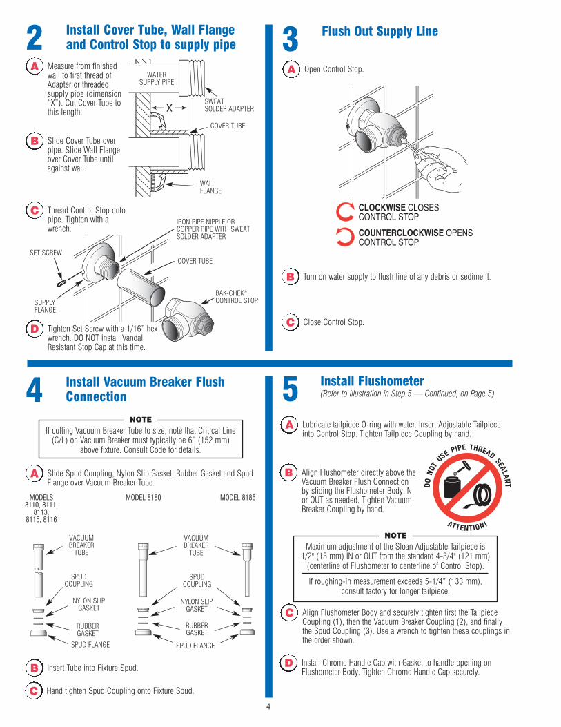
5 Install Flushometer(Refer to Illustration in Step 5 — Continued, on Page 5)
C Align Flushometer Body and securely tighten first the TailpieceCoupling (1), then the Vacuum Breaker Coupling (2), and finallythe Spud Coupling (3). Use a wrench to tighten these couplings inthe order shown.
B Align Flushometer directly above theVacuum Breaker Flush Connectionby sliding the Flushometer Body INor OUT as needed. Tighten VacuumBreaker Coupling by hand.
A Lubricate tailpiece O-ring with water. Insert Adjustable Tailpieceinto Control Stop. Tighten Tailpiece Coupling by hand.
Maximum adjustment of the Sloan Adjustable Tailpiece is1/2" (13 mm) IN or OUT from the standard 4-3/4" (121 mm)
(centerline of Flushometer to centerline of Control Stop).
If roughing-in measurement exceeds 5-1/4” (133 mm),consult factory for longer tailpiece.
NOTE
4 Install Vacuum Breaker FlushConnection
SPUDCOUPLING
RUBBERGASKET
SPUD FLANGE
A Slide Spud Coupling, Nylon Slip Gasket, Rubber Gasket and SpudFlange over Vacuum Breaker Tube.
B Insert Tube into Fixture Spud.
C Hand tighten Spud Coupling onto Fixture Spud.
VACUUMBREAKER
TUBE
SPUDCOUPLING
NYLON SLIPGASKET
RUBBERGASKET
SPUD FLANGE
MODELS8110, 8111,
8113, 8115, 8116
MODEL 8180 MODEL 8186
D Install Chrome Handle Cap with Gasket to handle opening onFlushometer Body. Tighten Chrome Handle Cap securely.
If cutting Vacuum Breaker Tube to size, note that Critical Line(C/L) on Vacuum Breaker must typically be 6” (152 mm)
above fixture. Consult Code for details.
NOTE
VACUUMBREAKER
TUBE
NYLON SLIPGASKET
2 Install Cover Tube, Wall Flangeand Control Stop to supply pipe
Thread Control Stop ontopipe. Tighten with awrench.
BAK-CHEK®
CONTROL STOP
COVER TUBE
IRON PIPE NIPPLE ORCOPPER PIPE WITH SWEATSOLDER ADAPTER
SET SCREW
SUPPLYFLANGE
WATERSUPPLY PIPE
SWEAT SOLDER ADAPTER
COVER TUBE
WALLFLANGE
A Measure from finishedwall to first thread ofAdapter or threadedsupply pipe (dimension“X”). Cut Cover Tube tothis length.
B Slide Cover Tube overpipe. Slide Wall Flangeover Cover Tube untilagainst wall.
C
Tighten Set Screw with a 1/16” hexwrench. DO NOT install VandalResistant Stop Cap at this time.
D
3 Flush Out Supply Line
A Open Control Stop.
C Close Control Stop.
B Turn on water supply to flush line of any debris or sediment.
5
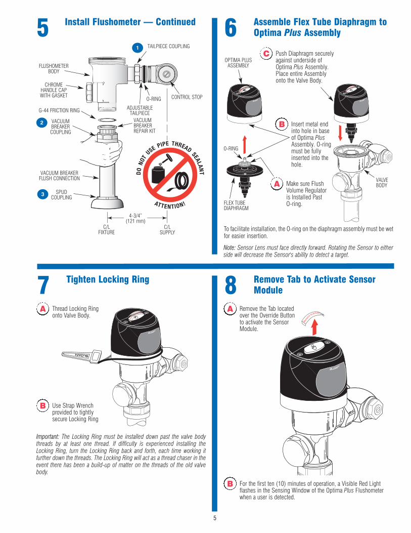
6 Assemble Flex Tube Diaphragm toOptima Plus Assembly
OPTIMA PLUSASSEMBLY
B Insert metal endinto hole in baseof Optima PlusAssembly. O-ringmust be fullyinserted into thehole.
A Make sure FlushVolume Regulatoris Installed PastO-ring.
O-RING
VALVEBODY
FLEX TUBEDIAPHRAGM
C Push Diaphragm securelyagainst underside ofOptima Plus Assembly.Place entire Assemblyonto the Valve Body.
A Thread Locking Ringonto Valve Body.
7 Tighten Locking Ring
B Use Strap Wrenchprovided to tightlysecure Locking Ring
Important: The Locking Ring must be installed down past the valve bodythreads by at least one thread. If difficulty is experienced installing theLocking Ring, turn the Locking Ring back and forth, each time working itfurther down the threads. The Locking Ring will act as a thread chaser in theevent there has been a build-up of matter on the threads of the old valvebody.
A Remove the Tab locatedover the Override Buttonto activate the SensorModule.
8 Remove Tab to Activate SensorModule
B For the first ten (10) minutes of operation, a Visible Red Lightflashes in the Sensing Window of the Optima Plus Flushometerwhen a user is detected.
5 Install Flushometer — Continued
G-44 FRICTION RING
C/LSUPPLY
ADJUSTABLETAILPIECE
C/LFIXTURE
CONTROL STOPO-RING
TAILPIECE COUPLING
VACUUM BREAKERFLUSH CONNECTION
VACUUMBREAKERCOUPLING
FLUSHOMETERBODY
SPUDCOUPLING
4-3/4”(121 mm)
1
2
3
CHROMEHANDLE CAPWITH GASKET
VACUUMBREAKERREPAIR KIT
Note: Sensor Lens must face directly forward. Rotating the Sensor to eitherside will decrease the Sensor's ability to detect a target.
To facilitate installation, the O-ring on the diaphragm assembly must be wetfor easier insertion.

1. A continuous, INVISIBLE light beam is emitted from the Optima PlusSensor.
2. As the user enters the beam's effective range, 22 to 42 inches (559 mmto 1067 mm) for closet installations and 15 to 30 inches (381 mm to762 mm) for urinal installations, the beam is reflected into the ScannerWindow to activate the Output Circuit. Once activated, the Output Circuitcontinues in a "hold" mode for as long as the user remains within theeffective range of the sensor.
3. When the user steps away, the loss of reflected light initiates anelectrical "one-time" signal that activates the flushing cycle to flush thefixture. The Circuit automatically resets and is ready for the next user.
6
Operation Range Adjustment (Adjust only ifNecessary)The Optima Plus has a factory set sensing range:Water Closet Models - 22" to 42" (559 mm to 1067 mm)Urinal Models - 15" to 30" (381 mm to 762 mm)
The Factory setting should be satisfactory for most installations.
If the range is too short (i.e., not picking up users) or too long (i.e., pickingup opposite wall or stall door) the range can be adjusted.
Note: Water does not have to be turned off to adjust range.
Refer to Illustration on Next Page.Loosen the two Screws on top of the unit. Remove the Override Button.Remove the Rubber Plug from top of Electronic Sensor Module to uncoverthe Potentiometer.
RANGE ADJUSTMENT PROCEDUREFor the first ten (10) minutes of operation, a Visible Red Light flashes in theSensing Window of the Optima Plus Flushometer when a user is detected.This Visible Red Light feature can be reactivated after ten (10) minutes byopening and closing the Battery Compartment Door.Check the range by stepping toward the unit until the Red Light flashes,indicating the Sensor's maximum detection limit. Adjust the RangePotentiometer Screw located on top of the Sensor Module a few degreesCLOCKWISE to increase the range or a few degrees COUNTERCLOCKWISEto decrease the range. Repeat this adjustment until the desired range isachieved.
Always Determine the Sensing Range with Plastic Cover and Lens WindowOn Top of the Unit.
(Continued on next page.)
B Stand in front of Sensorfor ten (10) seconds.
9 Test Sensor Operation
C Step away from Sensorand listen for “CLICK.”
A Test Sensor with Coverin Place.
The Optima Plus has a factory set sensing range:Water Closet Models - 22" to 42" (559 mm to 1067 mm)Urinal Models - 15" to 30" (381 mm to 762 mm)
The Factory setting should be satisfactory for most installations. If a rangeadjustment is required, refer to the Range Adjustment instructions on thispage.
10 Adjust Control Stop and InstallVandal Resistant Stop Cap
D For RESS retrofit applications, reuse Stop Cap from existing valve.In complete valve installations, a new Stop Cap is provided.
B Activate Flushometer byplacing hand in front ofOptima Plus SensorLens for ten (10)seconds (or pressoverride button) andthen moving it away.
A Open Control Stop COUNTERCLOCKWISE ½ turn from closedposition.
C Adjust Control Stop after each flush until the rate of flow deliveredproperly cleanses the fixture.
Important: The Sloan Flushometer is engineered for quiet operation.Excessive water flow creates noise, while too little water flow may not satisfythe needs of the fixture. Proper adjustment is made when plumbing fixtureis cleansed after each flush without splashing water out from the lip AND aquiet flushing cycle is achieved.Important: The Control Stop should never be opened to the point where theflow from the valve exceeds the flow capability of the fixture. In the event ofa valve failure, the fixture must be able to accommodate a continuous flowfrom the valve.
7
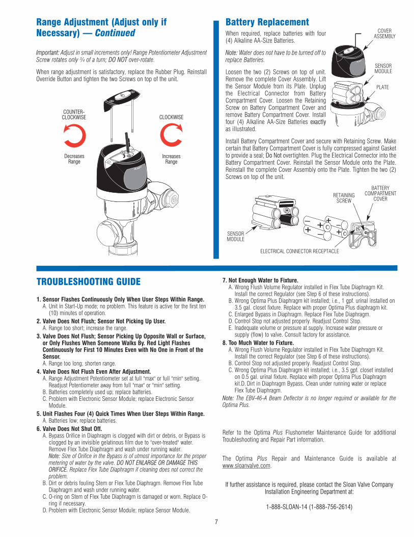
Important: Adjust in small increments only! Range Potentiometer AdjustmentScrew rotates only ¾ of a turn; DO NOT over-rotate.
When range adjustment is satisfactory, replace the Rubber Plug. ReinstallOverride Button and tighten the two Screws on top of the unit.
COUNTER-CLOCKWISE CLOCKWISE
DecreasesRange
IncreasesRange
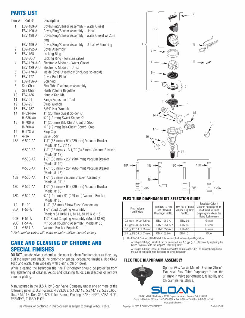
Range Adjustment (Adjust only ifNecessary) — Continued When required, replace batteries with four
(4) Alkaline AA-Size Batteries.
Note: Water does not have to be turned off toreplace Batteries.
Loosen the two (2) Screws on top of unit.Remove the complete Cover Assembly. Liftthe Sensor Module from its Plate. Unplugthe Electrical Connector from BatteryCompartment Cover. Loosen the RetainingScrew on Battery Compartment Cover andremove Battery Compartment Cover. Installfour (4) Alkaline AA-Size Batteries exactlyas illustrated.
Install Battery Compartment Cover and secure with Retaining Screw. Makecertain that Battery Compartment Cover is fully compressed against Gasketto provide a seal; Do Not overtighten. Plug the Electrical Connector into theBattery Compartment Cover. Reinstall the Sensor Module onto the Plate.Reinstall the complete Cover Assembly onto the Plate. Tighten the two (2)Screws on top of the unit.
Battery Replacement
BATTERYCOMPARTMENT
COVER
ELECTRICAL CONNECTOR RECEPTACLE
SENSORMODULE
RETAININGSCREW
COVERASSEMBLY
SENSORMODULE
PLATE
TROUBLESHOOTING GUIDE
1. Sensor Flashes Continuously Only When User Steps Within Range.A. Unit in Start-Up mode; no problem. This feature is active for the first ten
(10) minutes of operation.2. Valve Does Not Flush; Sensor Not Picking Up User.
A. Range too short; increase the range.3. Valve Does Not Flush; Sensor Picking Up Opposite Wall or Surface,
or Only Flushes When Someone Walks By. Red Light FlashesContinuously for First 10 Minutes Even with No One in Front of theSensor.A. Range too long; shorten range.
4. Valve Does Not Flush Even After Adjustment.A. Range Adjustment Potentiometer set at full "max" or full "min" setting.
Readjust Potentiometer away from full "max" or "min" setting.B. Batteries completely used up; replace batteries.C. Problem with Electronic Sensor Module; replace Electronic Sensor
Module.5. Unit Flashes Four (4) Quick Times When User Steps Within Range.
A. Batteries low; replace batteries.6. Valve Does Not Shut Off.
A. Bypass Orifice in Diaphragm is clogged with dirt or debris, or Bypass isclogged by an invisible gelatinous film due to "over-treated" water.Remove Flex Tube Diaphragm and wash under running water.Note: Size of Orifice in the Bypass is of utmost importance for the propermetering of water by the valve. DO NOT ENLARGE OR DAMAGE THISORIFICE. Replace Flex Tube Diaphragm if cleaning does not correct theproblem.
B. Dirt or debris fouling Stem or Flex Tube Diaphragm. Remove Flex TubeDiaphragm and wash under running water.
C. O-ring on Stem of Flex Tube Diaphragm is damaged or worn. Replace O-ring if necessary.
D. Problem with Electronic Sensor Module; replace Sensor Module.
7. Not Enough Water to Fixture.A. Wrong Flush Volume Regulator installed in Flex Tube Diaphragm Kit.
Install the correct Regulator (see Step 6 of these instructions).B. Wrong Optima Plus Diaphragm kit installed; i.e., 1 gpf. urinal installed on
3.5 gal. closet fixture. Replace with proper Optima Plus diaphragm kit.C. Enlarged Bypass in Diaphragm. Replace Flex Tube Diaphragm.D. Control Stop not adjusted properly. Readjust Control Stop.E. Inadequate volume or pressure at supply. Increase water pressure or
supply (flow) to valve. Consult factory for assistance.8. Too Much Water to Fixture.
A. Wrong Flush Volume Regulator installed in Flex Tube Diaphragm Kit.Install the correct Regulator (see Step 6 of these instructions).
B. Control Stop not adjusted properly. Readjust Control Stop.C. Wrong Optima Plus Diaphragm kit installed; i.e., 3.5 gpf. closet installed
on 0.5 gal. urinal fixture. Replace with proper Optima Plus Diaphragmkit.D. Dirt in Diaphragm Bypass. Clean under running water or replaceFlex Tube Diaphragm.
Note: The EBV-46-A Beam Deflector is no longer required or available for theOptima Plus.
Refer to the Optima Plus Flushometer Maintenance Guide for additionalTroubleshooting and Repair Part information.
The Optima Plus Repair and Maintenance Guide is available atwww.sloanvalve.com.
If further assistance is required, please contact the Sloan Valve CompanyInstallation Engineering Department at:
1-888-SLOAN-14 (1-888-756-2614)
PARTS LIST
SLOAN VALVE COMPANY • 10500 Seymour Avenue • Franklin Park, IL 60131Phone: 1-800-9-VALVE-9 or 1-847-671-4300 • Fax: 1-800-447-8329 or 1-847-671-4380
www.sloanvalve.com
Copyright © 2008 SLOAN VALVE COMPANY Printed 02-08The information contained in this document is subject to change without notice.
Item # Part # Description
1 EBV-189-A Cover/Ring/Sensor Assembly - Water ClosetEBV-190-A Cover/Ring/Sensor Assembly - UrinalEBV-198-A Cover/Ring/Sensor Assembly - Water Closet w/ Zurn
ringEBV-199-A Cover/Ring/Sensor Assembly - Urinal w/ Zurn ring
2 EBV-192-A Cover Assembly3 EBV-168 Locking Ring
EBV-30-A Locking Ring - for Zurn valves4 EBV-129-A-C Electronic Module - Water Closet
EBV-129-A-U Electronic Module - Urinal5 EBV-170-A Inside Cover Assembly (includes solenoid)6 EBV-177 Cover Rest Plate7 EBV-136-A Solenoid8 See Chart Flex Tube Diaphragm Assembly9 See Chart Flush Volume Regulator10 EBV-186 Handle Cap Kit11 EBV-91 Range Adjustment Tool12 EBV-22 Strap Wrench13 EBV-137 7/64” Hex Wrench14 H-634-AA 1” (25 mm) Sweat Solder Kit
H-636-AA ¾” (19 mm) Sweat Solder Kit15 H-700-A 1” (25 mm) Bak-Chek® Control Stop
H-700-A ¾” (19 mm) Bak-Chek® Control Stop16 H-573-A Stop Cap17 A-3A Valve Body
18A V-500-AA 1½” (38 mm) x 9” (229 mm) Vacuum Breaker(Model 8110/8111)
V-500-AA 1½” (38 mm) x 13 1/2” (343 mm) Vacuum Breaker(Model 8113)
V-500-AA 1½” (38 mm) x 23” (584 mm) Vacuum Breaker(Model 8115)
V-500-AA 1½” (38 mm) x 26” (660 mm) Vacuum Breaker(Model 8116)
18B V-500-AA 1½” (38 mm) Vacuum Breaker Assembly(Model 8137) *
18C V-500-AA 1¼” (32 mm) x 9” (229 mm) Vacuum Breaker(Model 8180)
18D V-500-AA ¾” (19 mm) x 9” (229 mm) Vacuum Breaker(Model 8186)
19 F-109 1 ½” (38 mm) Elbow Flush Connection20A F-56-A 1½” Spud Coupling Assembly
(Models 8110/8111, 8113, 8115 & 8116)20B F-55-A 1¼” Spud Coupling Assembly (Model 8180)20C F-54-A ¾” Spud Coupling Assembly (Model 8186)21 V-551-A Vacuum Breaker Repair Kit
* Part number varies with valve model variation; consult factory.
CARE AND CLEANING OF CHROME ANDSPECIAL FINISHESDO NOT use abrasive or chemical cleaners to clean Flushometers as they maydull the luster and attack the chrome or special decorative finishes. Use ONLYsoap and water, then wipe dry with clean cloth or towel.While cleaning the bathroom tile, the Flushometer should be protected fromany splattering of cleaner. Acids and cleaning fluids can discolor or removechrome plating.
Manufactured in the U.S.A. by Sloan Valve Company under one or more of thefollowing patents: U.S. Patents: 4,893,039; 5,169,118; 5,244,179; 5,295,655;Des. 345,113; Des. 355,478. Other Patents Pending. BAK-CHEK®, PARA-FLO®,PERMEX®, TURBO-FLO®.
1514
18A
2
18B 18C
20A 20B 20C
3
1
5
8
17
12
11
9
13
4
10
Optima Plus Valve Models Feature Sloan’sExclusive Flex Tube Diaphragm™ for theultimate in valve performance, reliability andChloramine resistance.
FLEX TUBE DIAPHRAGM ASSEMBLY
FLEX TUBE DIAPHRAGM KIT SELECTION GUIDE
Flush Volumeand Fixture
Item No. 10 FlexTube Standard
Diaphragm Kit No.
Item No. 11 FlushVolume Regulator
Part No.
Regulator Color †Color of Regulator to be
used with Flex TubeDiaphragm to obtain the
listed flush volume0.5 gpf/1.9 Lpf Urinal EBV-1050-A EBV-95 Green
1.0 gpf/3.8 Lpf Urinal EBV-1051-A † EBV-95 Green
1.6 gpf/6.0 Lpf Closet EBV-1053-A † EBV-95 Green
2.4 gpf/9.0 Lpf Closet EBV-1052-A EBV-101 Blue
16
6
7
† The EBV-1051-A and EBV-1053-A Kits are supplied with multiple Regulators. A 1.0 gpf (3.8 Lpf) Urinal kit can be converted to a 1.5 gpf (5.7 Lpf) Urinal by replacing theGreen Regulator with the supplied Black Regulator.A 1.6 gpf (6.0 Lpf) Closet kit can be converted to a 3.5 gpf (13.2 Lpf) Closet by replacingthe Green Regulator with the supplied White Regulator.
21
18C
19


![REVISION RECORD FOR THE STATE OF CALIFORNIA ERRATA 403.2.1 Water Closets on or after July 1, 2011 [HCD 1 & HCD 2] Water closets, either flush tank, flushometer tank, or flushometer](https://img.pdfslide.us/doc/110x75/5f7a09ab7c8b8818aa6485b5/revision-record-for-the-state-of-california-errata-40321-water-closets-on-or-after.jpg)